Acquisition and Transmission of Basic Environmental Factors for Agriculture using Internet-of-Things Concept
Info: 10779 words (43 pages) Dissertation
Published: 17th Feb 2022
Tagged: Information TechnologyFarming
Abstract
Economy of Saskatchewan mostly dependent on agriculture and it is considered as bread basket of Canada and the World. Saskatchewan is a prairie province and it has total area of 651,900 square kilometers and a population of 1114170[1]. The population density in Saskatchewan is 1.8 person per square kilometer which is very low. Saskatchewan economy is mainly dependent on agriculture. Agricultural crops are mostly dependent on basic parameters to yield the maximum output. These parameters can vary from crop to crop but basic parameters that are vital in agriculture are temperature [2], humidity, sunlight intensity, and wind speed. Taking care of each crop on a daily basis for farmers is nearly impossible considering vast lands of Saskatchewan. So the purpose of this project is to make the agricultural practices easier for farmers. To achieve this goal numerous factors and devices have to be analyzed to find the optimum solution by considering cost and energy efficient devices. By this project it is accomplished to make these parameters accessible on the internet which can be accessed via internet browser and on cellphone app. So in odd conditions, immediate attention can be given. This lies under the concept of Internet of things, which is defined as a connection between devices that can be controlled and communicate with each other over internet [4].
Table of contents
Click to expand Table of Contents
CHAPTER 1…………………………………………………….7
Introduction
CHAPTER 2…………………………………………………..10
Review of devices Used
2.1 Raspberry pi………………………………………………10
2.2 Xbee pro…………………………………………………13
2.3 Arduino mega 2560…………………………………………18
2.4 Relay module……………………………………………..21
2.5 USB WI-FI hotspot…………………………………………..21
2.6 USB WI-FI adapter………………………………………….22
Chapter 3…………………………………………………….23
Hardware
Chapter 4…………………………………………………….27
Software
4.1 Raspberry pi………………………………………………27
4.1.1 How to setup raspberry pi………………………………….27
4.1.2 Setup SD Card…………………………………………..27
4.1.3 Serial Port configuration…………………………………..29
4.2 Xbee Pro…………………………………………………33
4.3 Arduino Mega 2560…………………………………………38
Chapter 5…………………………………………………….41
Coding
5.1 Arduino Mega 2560………………………………………..41
5.2 Raspberry pi………………………………………………43
5.2.1 Android app……………………………………………48
5.2.2 Raspberry pi auto login……………………………………53
5.2.3 Executing python script in start……………………………..55
Chapter 6…………………………………………………….57
Results
6.1 Cost……………………………………………………58
6.2 Power consumption…………………………………………59
6.2.1 Raspberry pi……………………………………………59
6.2.2 Xbee pro………………………………………………60
6.2.3 Arduino Mega 2560………………………………………60
6.2.4 HUAWEI LTE E8372 Hotspot stick…………………………….60
Chapter 7…………………………………………………….61
Conclusions and Future work
Appendix…………………………………………………….63
References…………………………………………………..68
List of figures
Figure 1.1 Overview of system……………………………….9
Figure 2.1 Raspberry pi…………………………………..11
Figure 2.2 Raspberry pi pin configuration……………………….11
Figure 2.3 GPIO ……………………………………….12
Figure 2.4 Xbee pro……………………………………..14
Figure 2.5 Xbee data flow…………………………………16
Figure 2.6 Data frame……………………………………17
Figure 2.7 Frame structure………………………………..18
Figure 2.8 Xbee pro……………………………………..18
Figure 2.9 Pin configuration………………………………..20
Figure 2.10 Turbo stick…………………………………..21
Figure 2.11 Wi-Fi adapter…………………………………22
Figure 3.1 RTU………………………………………..23
Figure 3.2 Data flow…………………………………….24
Figure 3.3 MTU………………………………………..25
Figure 3.4 MTU-Raspberry pi connection………………………..25
Figure 3.5 Arduino-Relay connection………………………….26
Figure 4.1 Raspberry pi GUI…………………………………29
Figure 4.2 Serial port initialization……………………………..30
Figure 4.3 cmdline.txt edit………………………………….31
Figure 4.4 XCTU………………………………………..33
Figure 4.5 XCTU settings…………………………………..34
Figure 4.6 XCTU settings…………………………………..34
Figure 4.7 XCTU settings…………………………………..35
Figure 4.8 XCTU settings…………………………………..35
Figure 4.9 Arduino environment………………………………39
Figure 4.10 Processor selection……………………………….39
Figure 4.11 Arduino environment………………………………40
Figure 5.1 Arduino environment………………………………41
Figure 5.2 Python……………………………………….44
Figure 5.3 Python shell…………………………………….45
Figure 5.4 New window……………………………………45
Figure 5.5 Data sparkfun…………………………………..47
Figure 5.6 Android app……………………………………49
Figure 5.7 App making…………………………………….49
Figure 5.8……………………………………………50
Figure 5.9……………………………………………50
Figure 5.10…………………………………………..51
Figure 5.11…………………………………………..51
Figure 5.12…………………………………………..52
Figure 5.13…………………………………………..52
Figure 5.14…………………………………………..53
Figure 5.15…………………………………………..53
Figure 5.16…………………………………………..54
Figure 6.1 Data…………………………………………57
Figure 6.2 Data on app…………………………………….58
Figure 6.3 Xbee………………………………………..60
List of tables
Table 2.1-Technical specification…………………………….13
Table 2.2-Pin configuration of Xbee……………………………14
Table 2.3-Technical specifications……………………………19
CHAPTER 1: INTRODUCTION
Agriculture in Saskatchewan has a role of back bone in the economy and GDP of the province. Saskatchewan has led the world many times in wheat production and it is one of the biggest producer of canola in the region. Before dipping in to the engineering aspects of this project, there is a need to understand the significance of the agricultural parameters, and how much the output of crop depends on these parameters. The essential parameters for every crop are
- Temperature
- Humidity
- Water level
- Sun light intensity
- Wind speed
The outputs of all the crops are dependent on these parameters. Crop dependency on these parameters varies i.e. some parameters are more crucial to some crops and some are less. But each parameter plays their part in crop output. For example the wheat plant can be killed if excessive water stays in soil for almost three days. Crop yield losses because of water deficit exceeds all other factors combined [3]. Moreover, the serious damage to the tissues of plant can be caused if soil is excessively dry in a single day. Good farming demands to take care of environmental factors by monitoring them well and respond in case of any odd conditions.
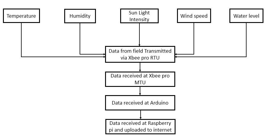
For this purpose the challenge was to introduce a standalone system that can be powered by renewable energy resources. In this project, solar panels have been used. This makes the whole unit power efficient so it may never run out of power without compromising on integral goals. In my part of this project, I have accomplished the communication of temperature and humidity and made the whole unit power efficient. Rest of the parameters can be added in the future work. Raspberry pi is used to upload the data onto the internet server and Arduino microcontroller is used as a primary device which controls all the data and turning on & off the Raspberry pi.
Xbee pro kit has been used to transmit and receive the data wirelessly from remote location to main location. Wireless USB device has been used to provide internet access. The data from the fields will be collected via different sensors which is then passed on to Xbee pro RTU(Remote Terminal Unit) which transmits the data wirelessly to MTU (Main terminal Unit) of Xbee pro kit after selected intervals of time. Arduino receives this signal from Xbee pro serially and turn on the USB Wi-Fi device and raspberry pi. After Raspberry pi turns on, this data is then uploaded to the internet servers automatically. After uploading the data, the raspberry pro turned off automatically and the system then goes back to hibernation state. The data uploaded on the servers can be accessed through internet browser. With the recent advancement in mobile communication and smart phones, users are more inclined towards the usage of mobile apps so the data have made accessible through android app as well.
By considering a lot of different options of devices that can serve the purpose, aforementioned devices has been selected because of their less cost and their durability. Through programming, these devices have been made to work with higher energy efficiency. The general working of the system has been shown in Figure 1.1.
Chapter 2: Review of devices used
This chapter will cover the details of the devices that have been used in this project. Their role in the project and their significance over other competitive devices are discussed.
Following are the devices that have been used in this project
- Raspberry pi
- Arduino mega
- Xbee pro
- Relays kit
- TP link USB adapter
- TP link bell USB WI-FI router
2.1 Raspberry pi
Raspberry pi is office card sized computer which can operate Linux operating system. This device has brought a new era in engineering world. This device is capable of connecting with Led monitors or with TV for display just like regular computers. It can be connected with mouse and key board through USB ports and it has the ability to connect with Wi-Fi internet via Wi-Fi USB adapter. Like a regular computer, one can use this device for making spread sheets, Internet browsing, playing videos or video games. Besides all of the capabilities discussed earlier, the main significance of this device is that it has GPIO pins just like ordinary microcontrollers that can be programmed. This brings endless options to implement different kind of projects. I/O ports of raspberry pi has been shown in Figure 2.1 and Figure 2.2.
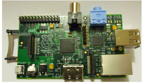
Figure 2.1 Raspberry pi
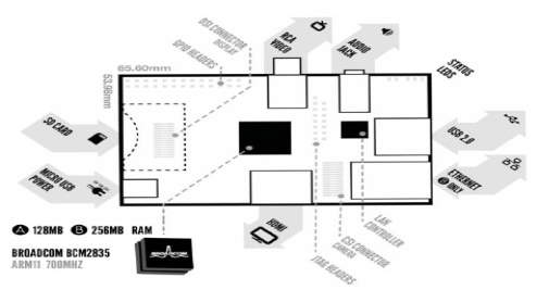
Figure 2.2 Raspberry pi pin configuration
Raspberry pi does not have any internal storage option, so it has SD card slot for storage purpose. Operating system of raspberry pi is installed in the SD card which is discussed step by step later on in this report. This device has two USB 2.0 ports for accessories connectivity, HDMI port for visual interface but this device does not have VGA port. Raspberry pi can be connected with Internet, through Ethernet cable and it has standard RJ45 connector port and via USB Wi-Fi adapter. Taking into account that it has only two USB ports, if more devices need to be connected with raspberry pi then USB hub can be interfaced. Besides that it has audio jack and video rca socket. Micro USB socket is used to power up the Raspberry pi. Moreover, it has 40 GPIO pins. Out of them some are I/O, VCC 5V, 3.3 V and serial communication pins as shown in Figure 2.3 these pins have been discussed in detail later in the report.
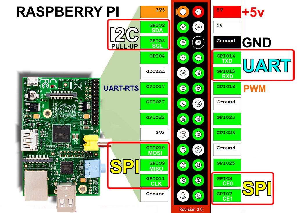
Figure 2.3 GPIO
2.2 Xbee Pro
Xbee pro RF modules are designed to provide low cost low power wireless networks. Xbee devices use less power and they are very durable in the delivery of data between the devices wirelessly. Xbee Pro works within the SRD 868 MHz frequency band .Main terminal unit of Xbee pro has been shown in Figure 2.4.
Technical specifications of Xbee pro are in following table.
Table 2.1-Technical specification
| Indoor/Urban range | Up to 1800 ft |
| Outdoor RF line of sight range | Up to 25 miles with 2 dB dipole antenna |
| Power output transmission | 85-500 mA, can be adjusted by power levels |
| RF data rate | 24 kb/s |
| Data throughput | 2.4 kb/s |
| UART | 3.3 V CMOS(5V tolerant) |
| Data rate | 1200-230400bps |
| Supply voltage | 3.0 to 3.6 VDC |
| Operating current | 500-800 mA |
| Sleep current | 55μA |

Figure 2.4 Xbee pro
The pin configuration and their details are tabled below.
Table 2.2-Pin configuration of Xbee
| Pin# | Name | Direction | Description |
| 1 | Vcc | – | Power supply |
| 2 | DOUT | Output | UART data out |
| 3 | DIN/ CONFIG | Input | UART data in |
| 4 | DIO12 | Either | Digital I/O 12 |
| 5 | RESET | Input/ open drain output | Module reset |
| 6 | PWM0/ RSSI /DIO10 | Either | PWM output 0/Rx signal strength indicator/digital IO |
| 7 | PWM/DIO11 | Either | PWM Output 1/digital I/O 11 |
| 8 | – | – | – |
| 9 | DTR / SLEEP_RQ/ DIO8 | Pin sleep control line or digital IO 8 | |
| 10 | GND | – | Ground |
| 11 | AD4/DIO4 | – | Analog input 4 / digital I/O 4 |
| 12 | CTS / DIO 7 | – | Clear to send flow control / digital I/O 7 |
| 13 | ON/SLEEP | OUTPUT | Module status indicator or digital I/O 9 |
| 14 | VREF | – | 2.6 V – Vcc |
| 15 | Associate /DIO5/AD5 | – | Associated indicator, digital I/O 5 |
| 16 | RTS/DIO6 | – | Request to send flow control/ digital I/O 6 |
| 17 | AD3/DIO6 | – | Analog input 3 / digital I/O 3 |
| 18 | AD2/DIO2 | – | Analog input 2 / digital I/O 2 |
| 19 | AD1 /DIO1 | – | Analog input 1/ digital I/O 1 |
| 20 | AD0/ DIO0 / Commissioning button | – | Analog input 0, digital I/o 0, or commissioning button. |
Serial communication
The Xbee pro connects to the Arduino microcontroller through asynchronous serial port. Arduino and Xbee pro can communicate at different UART.
UART
UART is abbreviated for Universal Asynchronous Receiver /Transmitter. So, the devices which support UART can be directly connected with Xbee pro for serial communication. Figure 2.5 shows how data flows between devices under UART.
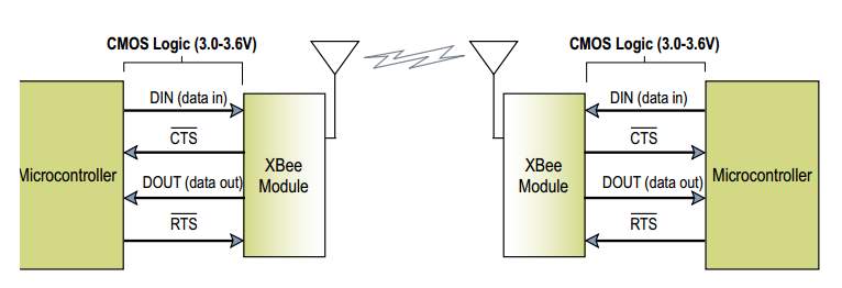
Figure 2.5 Xbee data flow
The data flows in to Xbee module from microcontroller onto pin 3 DIN as an asynchronous serial signal. The data bytes have its first bit low and stop bit high. Each byte has 8 data bits and transmitted with least significant bit first as shown in Figure 2.6.
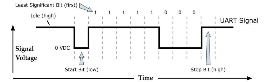
Figure 2.6 Data frame
From figure 2.6, 1 byte has been elaborated with respect to bits. The byte starts with start bit which is low and it ends at logic high, the last bit called as stop bit. UART controls the timing parity, checking this is vital for communication. UART configuration on both ends of the devices has to be same to make serial communication successful. UART includes baud rate, data bits, stop bits, start bits, and parity.
API frame
Xbee transmit its data in the form of API frame. It is very secure than ordinary data transmission. It supports two type of API frames but I am using AP=1 API operation
API (AP = 1)
To activate this mode of API we have to select AP= 1 and the data frame structure is shown in Figure 2.7
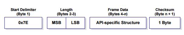
Figure 2.7 Frame structure
Data will be discarded before the start delimiter byte. In case of data disruption, the Xbee pro mentions the failure status.
2.3 Arduino Mega 2560
Arduino Mega 2560 is a microcontroller board which has ATmega 2560 microcontroller installed on it. The board has 54 Digital input/output pins, out of which 14 can be used for PWM output, and 16 as analog input pins. The most beneficial characteristic of Arduino mega 2560 is that it can supports 4 UART ports simultaneously. The board comes with 16MHz crystal oscillator and a USB connection. To power up it has power jack on the side of the board. It has ICSP header and a reset button. An overview of Xbee pro has been shown in Figure 2.8.
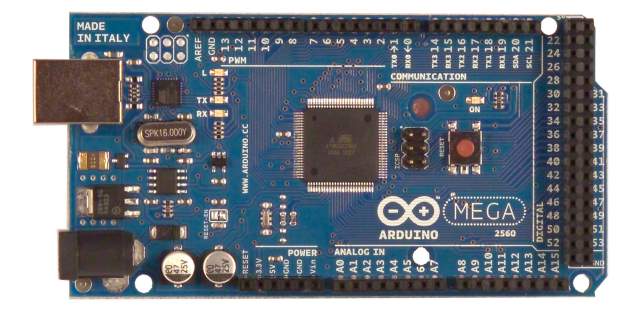
Figure 2.8 Xbee pro
Technical details of Arduino mega 2560 are tabled below.
Table 2.3-Technical specifications
| Microcontroller type | ATmega 2560 |
| Operating Voltage | 5V |
| Input voltage (Optimum) | 7-12V |
| Input Voltage(range) | 6-20V |
| Digital I/O Pins | 54 |
| Analog Input pins | 16 |
| DC current per I/O pin | 40 mA |
| DC current for 3.3 V pin | 50 mA |
| Flash Memory | 256 kb |
| SRAM | 8 kb |
| EEPROM | 4 kb |
| Clock speed | 16 MHz |
Arduino can be powered through USB port or with external power supply, Arduino selects power source automatically. In case of external power supply, the Voltage should be between 6 to 20 V but the recommended input voltage level is between 7 and 12 V. In case of 6 V as input the 5V pin may not provide 5V on the board and functions of Arduino would be unstable. Whereas, if supplied with more than 12 V, voltage regulator may heat up and cause damage to board so it is recommended to use 7-12 V.
Arduino mega use ATmega 2560 microcontroller which has 256 kb of flash memory to store the code. It has 8 KB SRAM and 4 KB of EEPROM. It also has 54 pins and they can be programmed to be used as INPUT or OUTPUT pins. It has 4 Serial pins
Serial0= pin 0(RX) & 1 for (TX), Serial 1= pin 19 for (RX) & 18 (TX), Serial 2= pin 17 for (RX) & 16 for (TX), Serial 3= pin 15 for (RX) & 14 for (TX). These pins can be used to communicate with other devices serially. Arduino has a capacity to use all 4 serials at a time. It has LED on board which shows the digital logic status of pin 13, when pin is high the light will turn on and it remains off at logic low. It has analog pins with which analog voltage output sensors or modules can be interfaced. It has polyfuse, which means if more than 500 mA current try to pass through the Arduino from computer the fuse will break the connection. Pin configuration has been shown in Figure 2.9.
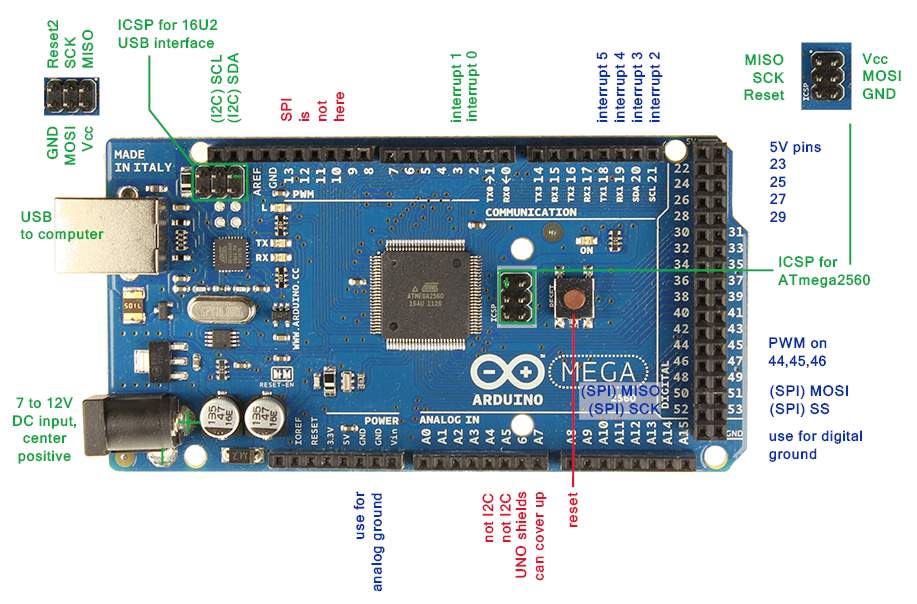
Figure 2.9 Pin configuration
2.4 Relay module
To turn on the raspberry pi and Hotspot stick relay module has been used. This relay module will provide the path between source and raspberry, as well as with WI-FI Hotspot stick at Logic low.
2.5 USB WI-FI Hotspot
HUAWEI LTE E8372 Hotspot Turbo Stick
To provide internet connectivity in a remote location 4G LTE HUAWEI hotspot stick has been used. It is provided by the BELL networks in Canada, its speed can soar up to 150 Mbps. When powered, it acts like a Wi-Fi hotspot. 10 devices can be connected with this device wirelessly, similar to standard router. Similarly some other Hotspot sticks are also available in market but they are not as handy as this and in addition to that the power consumption of those devices are higher as compared to this one.
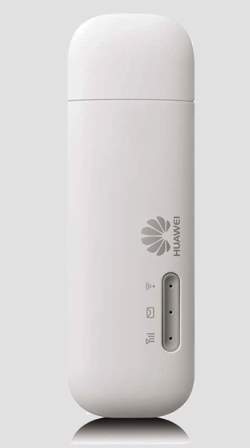
Figure 2.10 Turbo stick
2.6 USB WI-FI adapter
To connect raspberry pi to internet, two options can be approached, one through Ethernet port and the other through USB WI-FI adapter. In this project, USB WI-FI adapter TPLINK TL-WN725N has been used. This adapter will connect to USB hotspot stick wirelessly and provide a path to access internet servers.
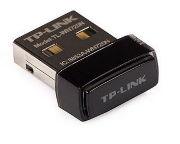
Figure 2.11 Wi-Fi adapter
Chapter 3: Hardware
In this chapter, hardware of the project has been elaborated. Hardware is the physical part of the project, hardware of all the devices that has been used in this project and their interconnections has been explained as follows
RTU MODULE
This Xbee Pro module is called as RTU (Remote Terminal Unit) as shown in Figure 3.1.
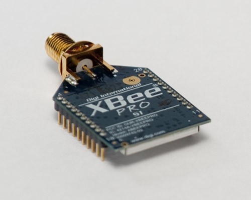
Figure 3.1 RTU
This module sits in a field and transmits the data to MTU (Main terminal Unit) wirelessly. This RTU has capability to connect with Omni directional antenna which enhance its range. RTU is interfaced with sensors through microcontroller which sends their output to RTU. RTU converts this data into API frame and transmits it as shown in Figure 3.2.
MTU
RTU
Figure 3.2 Data flow
MTU MODULE
On the other side, MTU is connected with Arduino mega. MTU receives the signal from RTU module wirelessly and send that data through serial port on to the Arduino microcontroller. The TX pin of the Xbee pro is connected with the RX1 pin on Arduino board and TX1 pin of Arduino is connected with RX pin of Xbee pro. To make serial communication accurate ground pins of both devices should be connected with each other [5].
Arduino is connected with raspberry pi through serial communication ports, the TXD pin of raspberry is connected with RX3 of Arduino and TX3 pin of Arduino is connected with the RXD pin of raspberry pi as shown in Figure 3.4.
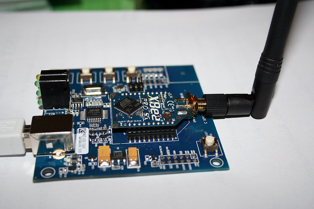
Figure 3.3 MTU
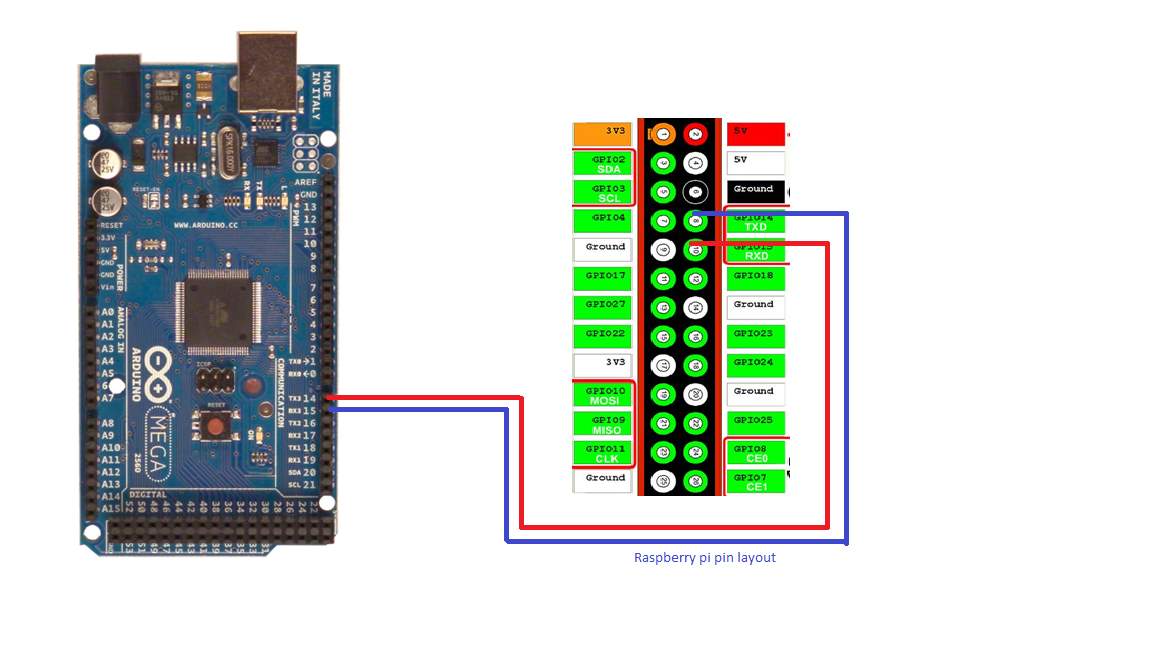
Figure 3.4 MTU-Raspberry pi connection
Arduino powers up the Raspberry pi and USB Hotspot device through a relay kit. The relay kit is connected with Arduino through output declared pin 13 as shown in Figure 3.5. The relay kit will be powered through external source.
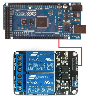
Figure 3.5 Arduino-Relay connection
To make this project power efficient this relay module has been used. Arduino will provide the logic high at its 13 output which provides switching in the relay module. This relay module is powered by external power supply so when relay switch their state, it completes the path between external power supply and raspberry pi, Wi-Fi hot spot device. The reason to use external power supply for raspberry pi and Wi-Fi hotspot device is that the output power capacity of Arduino is not high enough to power up these devices. So an indirect method has been adopted to achieve the purpose.
Chapter 4: Software
4.1 Raspberry pi
4.1.1 How to setup raspberry pi
Raspberry pi is a small computer but unlike regular computer it need little extra accessories to make it work.
- USB key board and mouse
- HDMI cable to connect with monitor for display
- Power cable(Micro USB) to power up the raspberry pi
- SD card. Raspberry pi operating system installed in the SD card. Without this pi will not work.
- Ethernet cable will be required to connect pi with internet
- USB Wi-Fi adapter to access internet wirelessly
4.1.2 Setup SD Card
To install an operating system into SD card few steps have to be followed. First we have to select card of storage capacity enough to accommodate the Linux system. So recommended storage capacity is 8 GB and higher. SD card should be formatted first then the latest version of Raspbian have to be installed. Raspbian is available on the website of raspberry pi under NOOBS section.
Procedure is explained in steps below:
- Download the latest Raspbian version from Raspberry pi official website, It is in .zip format, unzip the .zip file to any folder.
- Download Win32DiskImager, unzip the .exe file and install it.
- Insert the SD card into the SD card reader slot, SD card will be detected automatically, if it doesn’t, go to control panel then add SD card in add /remove device.
- Format the SD card.
- Open the Win32Diskimager and select the SD card if it’s not selected automatically Under Device tab. Now select the small folder icon just beside the device tab and browse the Raspbian .img file which was unzipped before. Select the write option, and it will began Burning image onto SD card, this may take some minutes.
Now Insert this SD card into SD card slot in Raspberry pi and connect HDMI cable in the HDMI slot for display and wireless mouse keyboard adapter in USB port. To access Wi-Fi wirelessly insert Wi-Fi adapter in USB slot, and power cable to power the Raspberry pi.
Once power turned on Raspberry pi will start booting. For the first time Raspberry will ask some settings to select once it reaches Raspi-config window. There would be a long list of settings but one have to select only expand_rootfs and Enter. After that select Finish option and press yes for reboot.
Rebooting will take some moment, after raspberry complete its reboot it will ask for Username and password.
By default
Username: Pi
Password: Raspberry
Then type startx in a command line to proceed towards the Linux Raspberry pi GUI. GUI is shown in Figure 4.1.
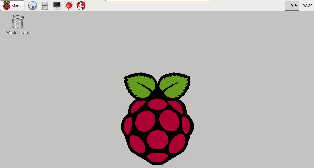
Figure 4.1 Raspberry pi GUI
4.1.3 Serial Port configuration
Raspberry pi will receive and transmit all the data through serial ports via serial communication. Raspberry pi has only one serial port, which by default cannot be accessed. To make serial port working, certain settings needs to be done. First we have to disable the console login so that it can be used for Project purpose.
First file that needs to be edited is inittab, it can be found under the directory/etc/inittab.
Remember it can only be edited in the Lxterminal or using console. It’s always recommended to login as SuperUser to make these changes.
One can login as SuperUser by typing Sudo su in command.
The inittab file contains the command that needs to be disabled to make serial port work for project. File will look like as shown in figure 4.2.
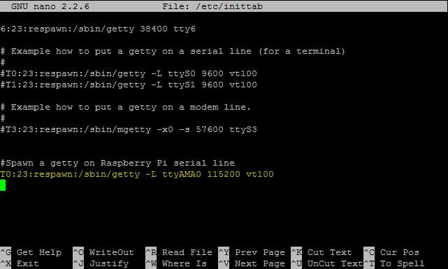
Figure 4.2 Serial port initialization
Last line is a command that needs to be disabled. It can be disabled by removing all the text written in it or it can be disabled by making it as comment which can be achieved by adding # in the start of line as shown [6].
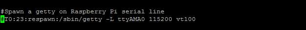
After editing, save the file and reboot the raspberry pi through a command [6] sudo shutdown –r now.
Second file that needs to be edited is cmdline.txt. The directory of this file is /boot/cmdline.txt
The file will look like as shown in figure 4.3.
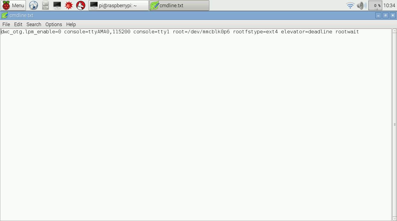
Figure 4.3 cmdline.txt edit
The command needs to be edited to make serial port work. Before edit, the command will look like the following:
dwc_otg.lpm_enable=0console=ttyAMA0,115200 kgdboc=ttyAMA0,115200 console=tty1 root=/dev/mmcblk0p2 rootfstype=ext4 elevator=deadline rootwait
The colored part should be removed from the command. After removing the colored part the command will look like the following:
dwc_otg.lpm_enable=0 console=tty1 root=/dev/mmcblk0p2 rootfstype=ext4 elevator=deadline rootwait.
Save the file and reboot the device by command sudo shutdown –r now.
The device is now ready to communicate serially. To verify that serial port is working properly, one easy test can be performed. Connect TXD pin with RXD pin. Minicom is the tool used for this and it can be downloaded by the following command sudo apt-get install minicom. After downloading, initiate the serial port by the command minicom -b 9600 -o -D /dev/ttyAMA0
If letters are echoing after typing, it implies that serial port is working at 9600 baud rate. If it’s not echoing check the wire connections [7][8][9].
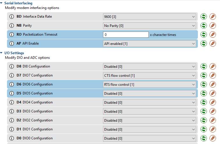
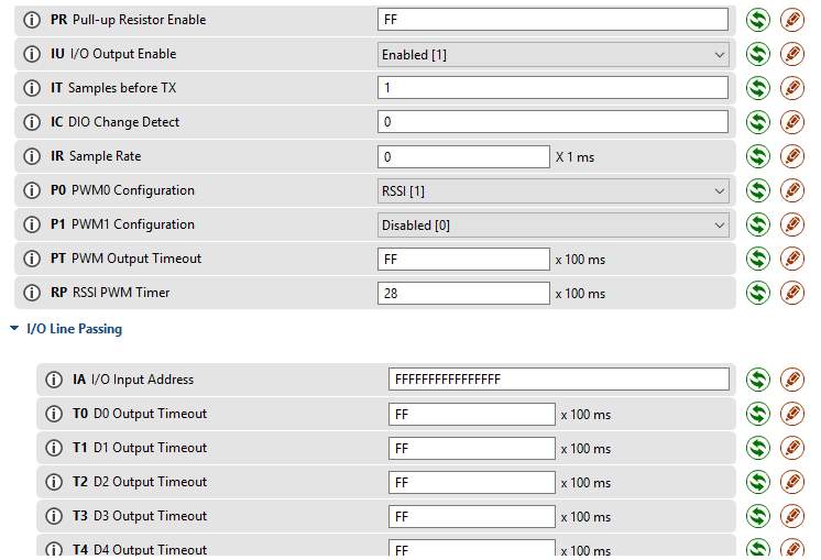
4.2 XBEE PRO
Xbee pro settings can be configured by XCTU software. The software can be downloaded using the following link:
https://www.digi.com/products/xbee-rf-solutions/xctu-software/xctu
After downloading and installing the XCTU software, window will open up as shown in Figure 4.4.
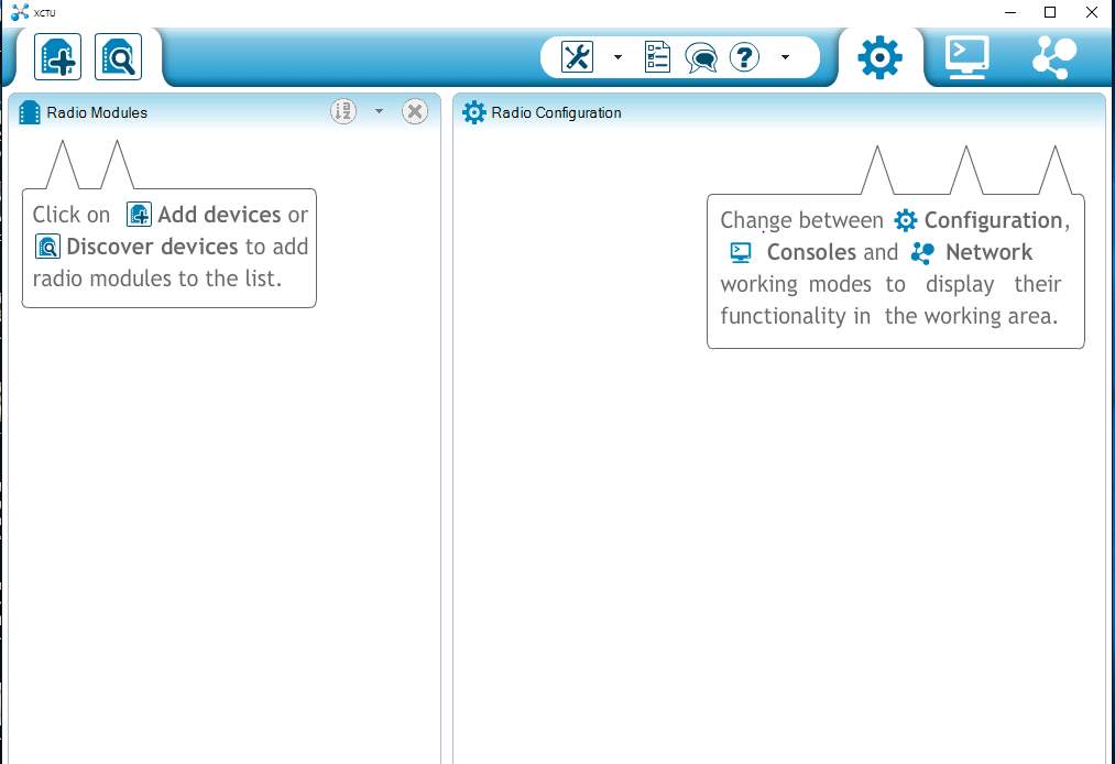
Figure 4.4 XCTU
Now select the Discover module icon as shown in Figure 4.5.
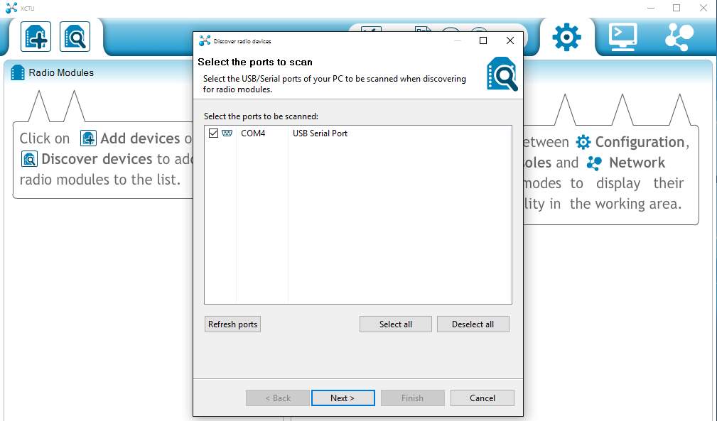
Figure 4.5 XCTU settings
Following window will appear, select the right COM port at which Xbee pro is connected as shown in Figure4.6.
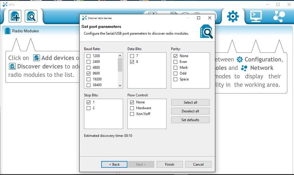
Figure 4.6 XCTU settings
Check the right settings to discover the module as shown in Figure 4.7, if not sure about the settings select all.
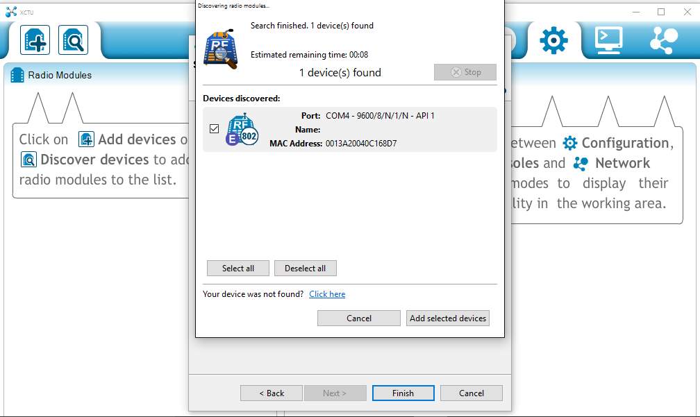
Figure 4.7 XCTU settings
The device will be discovered as shown in Figure 4.8, select the Add selected device option. If device is not detected press reset button on Xbee pro or troubleshoot the connected USB port.
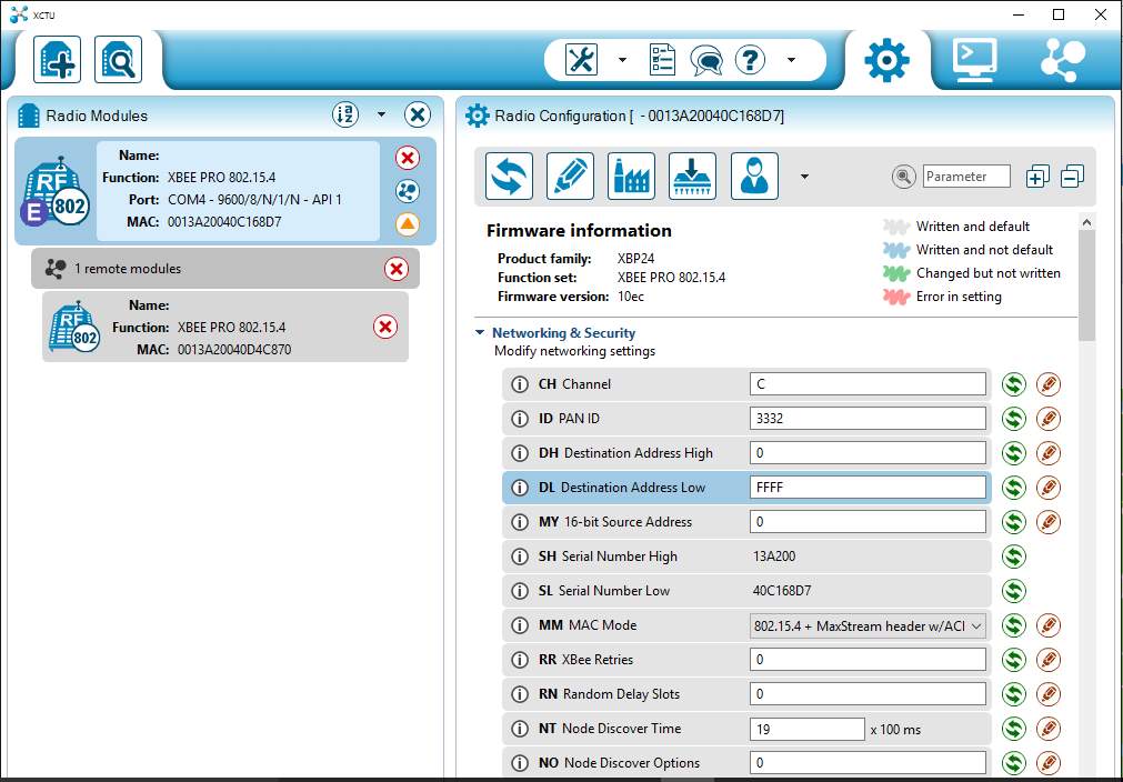
Figure 4.8 XCTU settings
Now select the radio module connected option to search for RTU radio terminal of Xbee pro. After searching it will appear in the tab.
Following are the settings of Xbee pro that needs to be configured.
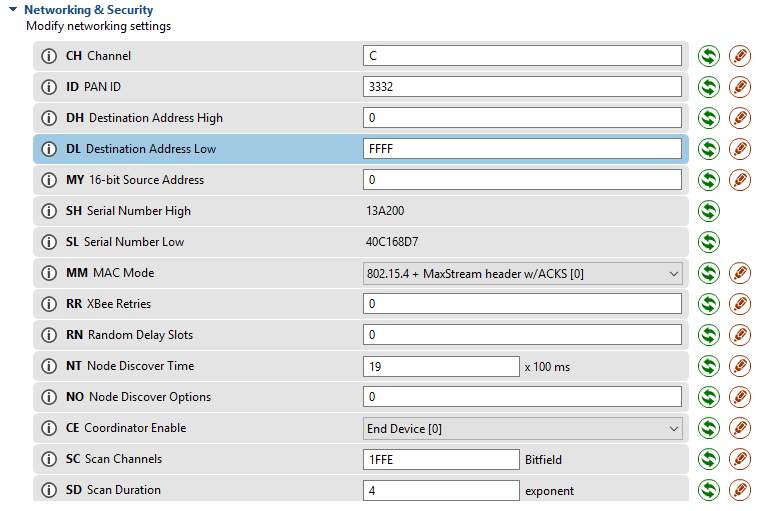
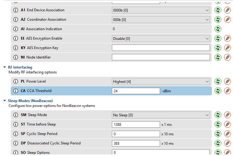
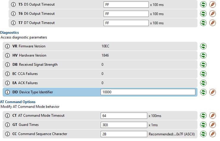
For cyclic sleep mode set SM=4 and ST needs to be configured accordingly.
4.3 ARDUINO MEGA 2560
Arduino microcontroller settings are not complex. Arduino programming software can be downloaded from the following website:
https://www.arduino.cc/en/Main/Software
After installation, go to Tools tab and select the board as shown in Figure 4.9. After selecting the right board select the Processor as shown in Figure 4.10. After selecting the correct board and the processor the programming environment will be created as show in Figure 4.11.
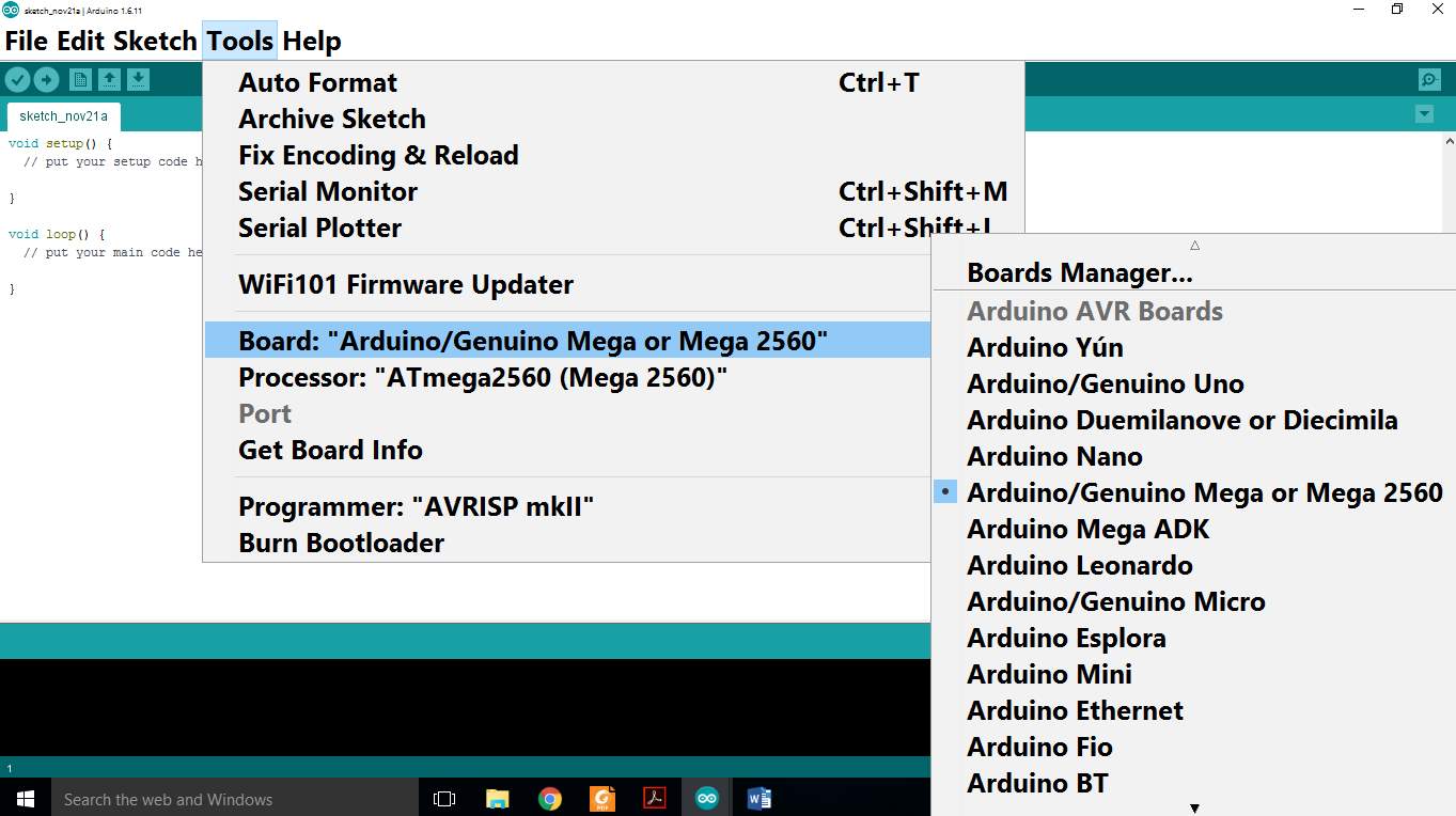
Figure 4.9 Arduino environment
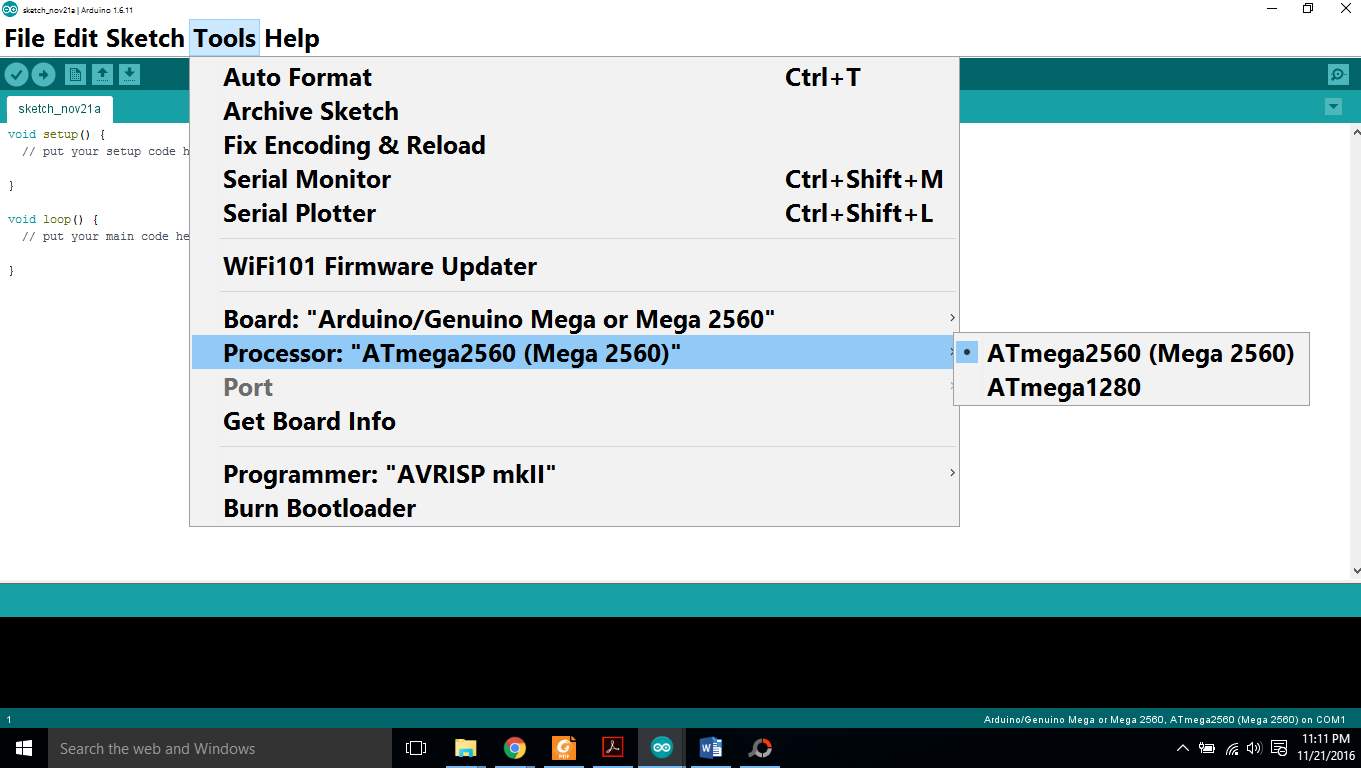
Figure 4.10 Processor selection
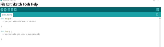
Figure 4.11 Arduino environment
At this point, Arduino is ready to use.
Chapter 5: Coding
After setting up the hardware and the software of devices now its turn for coding.
5.1 ARDUINO MEGA 2560
Arduino supports C/C++ language programming. C/C++ language is very popular in microcontroller programming software. The task of Arduino in this project is to make the whole unit power efficient. After the installation and settings of Arduino software the coding window will appear as shown in Figure 5.1.
Figure 5.1 Arduino environment
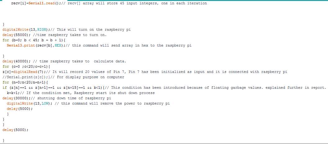
It starts with two basic functions Void setup and Void loop. Void setup will execute only at the start of program for once or when Arduino gets reset, inside the bracket all the pins and ports have to Initiated which will be used in Void loop section. Whereas Void loop is a forever loop, it keeps on executing until Arduino get reset. The main purpose of the Arduino Mega 2560 is to make the whole unit power efficient which has been achieved by the coding. Arduino receives the data from Xbee. The Arduino keeps on checking the data availability on its serial port if it receives the data it turns on the raspberry pi by and USB WI-FI module connected through same relay module beside storing data using For loop in array. Arduino waits for raspberry pi to boot and then it pass the data to raspberry pi, raspberry pi process the data and upload it to the internet server. After uploading the data, Raspberry pi gives logic 1 signal at Pin 7 of Arduino and raspberry pi turn off by itself which explained later in this chapter and Arduino removes the power from pin 13 which disable Relay module. Then Arduino will again look for data at the input of serial port 1 and this process keep on repeating. The process has been shown in block diagram.
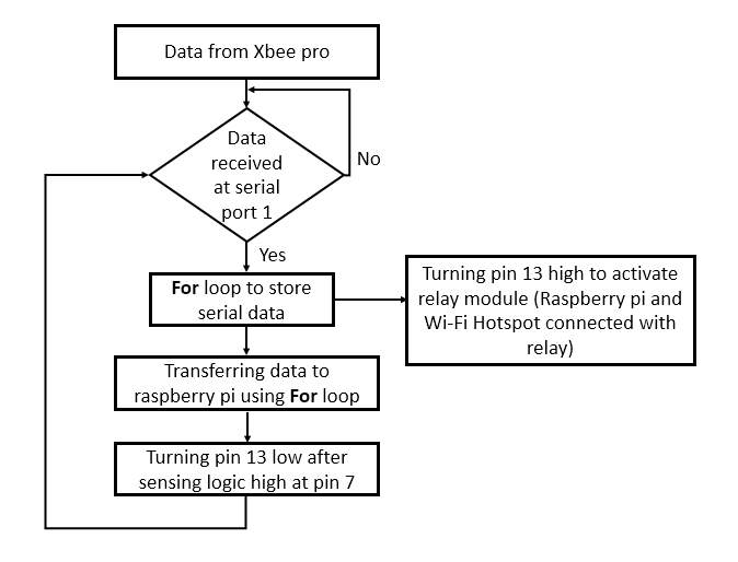
Block diagram
Coding file has been shown in Appendix.
5.2 Raspberry pi
Raspberry pi has Linux operating system and it works same as ordinary computers but it has additional 40 pins which makes it the best choice to integrate thousands of projects. Its pin acts the same way as microcontroller pins which enable it to interface with sensors and other devices. Moreover it supports the communication with other devices through serial port. This device is combination of microcontroller and computer.
Raspberry pi supports Python language for coding. Python language is simple and it is one of the most implemented language in coding world. Python 2 is a software in which coding has been implemented.
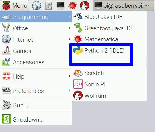
Figure 5.2 Python
Select the menu and programming then open up the Python 2 as shown in Figure 5.2.
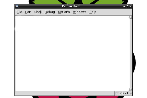
Figure 5.3 Python shell
Python shell will appear as shown in Figure 5.3, select File and the New Window to make script file for coding as shown in Figure 5.4.
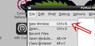
Figure 5.4 New window
Block diagram
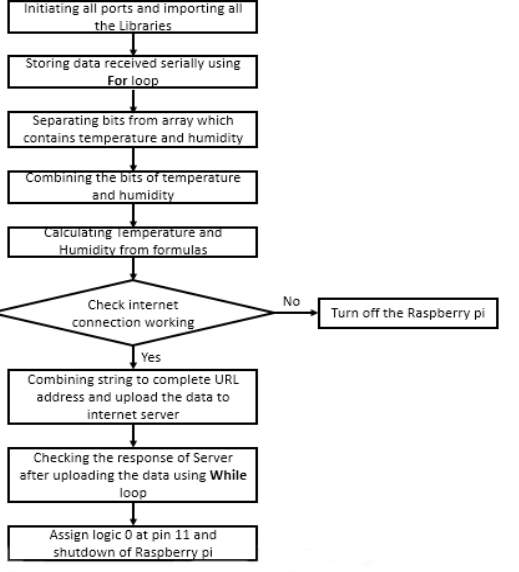
Raspberry pi in this project receiving the data from Arduino mega 2560 through serial port and then it process the data and upload it onto internet server and after that it turned off by itself. The whole process has been shown in block diagram. In the start of python script all the ports and pins needs to be initiated. Moreover, all the libraries should be imported in start. The Raspberry pi will store the data available at serial port from Arduino and store it in array using For loop.
The data received through serial port contains a lot of information bits along temperature and humidity bits, so the temperature and humidity bits separated from the array. Temperature and humidity comprises of more than one bit, so their bits combined after separating from array. Temperature and humidity have been calculated from formulas. Then raspberry will look for Internet connection, if internet is not working raspberry pi will give signal to turn it off and if it’s working raspberry pi will complete URL by combining the temperature and humidity value and uploaded onto the internet. After uploading the data to internet, raspberry pi will look for the response from internet server for successful attempt if it doesn’t get confirmation it will keep on trying to upload the data on to internet until it’s done. Raspberry bi starts shutting off and besides that it will communicate with Arduino to turn the power off after raspberry pi turned off. The coding has been included in Appendix.
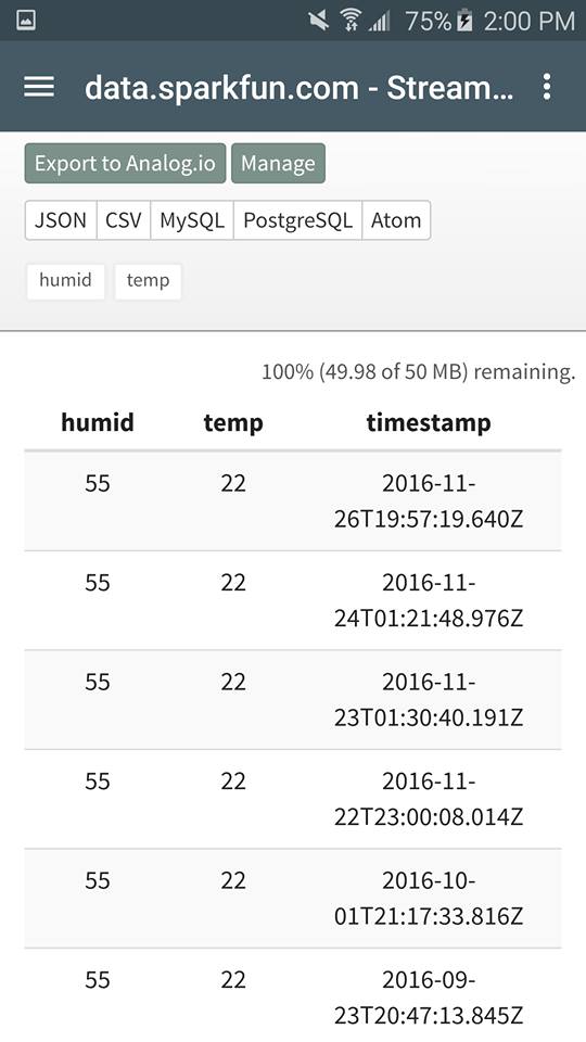
Aforementioned website has been used as server to upload data. It allows user to make profile and provide the private key and specific URL to upload the data onto the servers. Click the Create option to register for new account as shown in Figure 5.5.

Figure 5.5 Data sparkfun
After registration, data can be uploaded to sparkfun servers. The method to upload data is very simple. In this project temperature and humidity are the parameters that has been uploaded to this server so the URL assigned to this project is mentioned below.
Open the URL with humidity and temperature values in the spots mentioned in bold letters accordingly and data will be uploaded to servers. After it uploads the data, it will display 1 SUCCESS as shown

This “1 success” has been used in raspberry pi coding to confirm that data has been uploaded on the server.
5.2.1 Android app
Popularity of cell phones App has been increased dramatically in last decade. They are very easy to use and more easily accessible. An app has been developed for this project to access the data on cellphones. Procedure has been elaborated below
Open the URLwww.appyet.com
Register to make an account on the website and then login as shown in Figure 5.6.
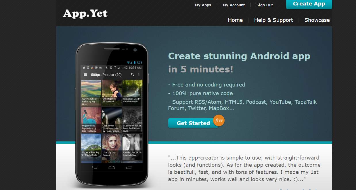
Figure 5.6 Android app
Select the App name as in Figure 5.7.
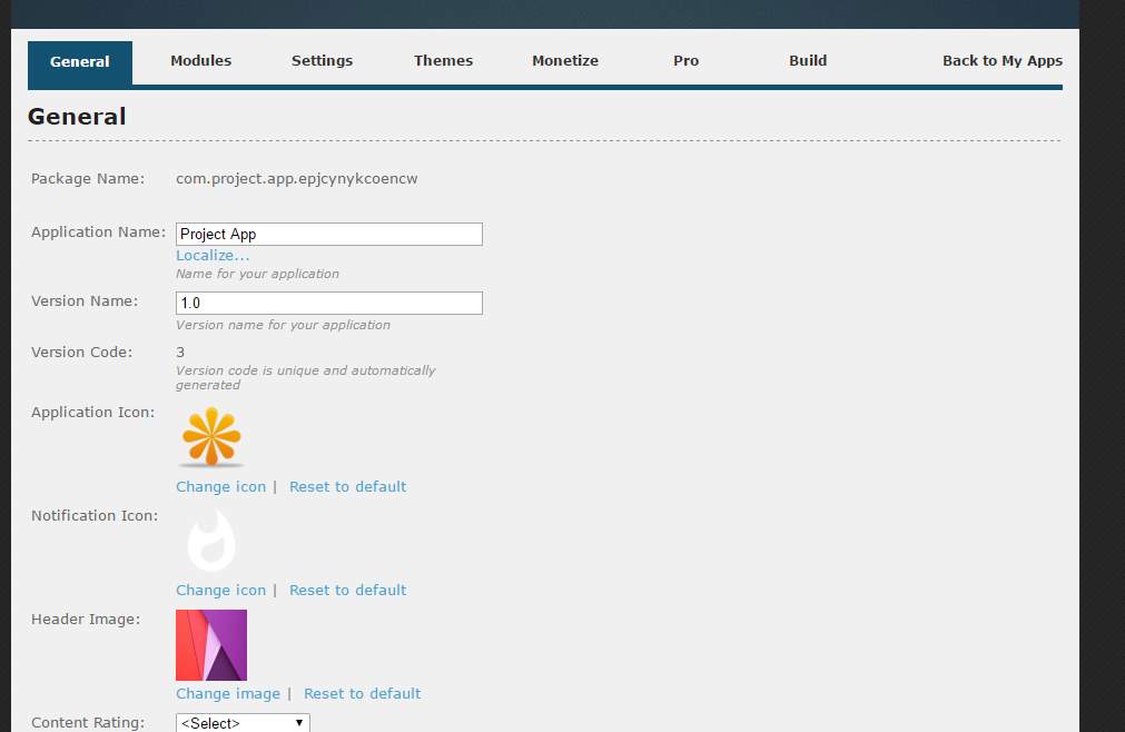
Figure 5.7 App making
Now select the Modules tab as in Figure 5.8.
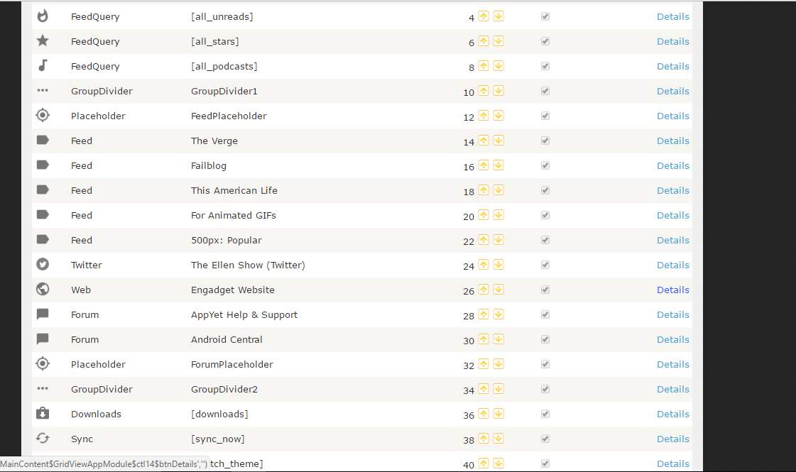
Figure 5.8
Click on details right across the Website icon as in Figure 5.9.
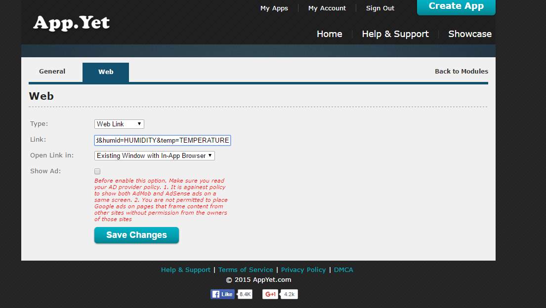
Figure 5.9
Now paste the URL and press save changes
Now remove all the Modules one by one by clicking on the details for example select Feed query as in Figure 5.10.
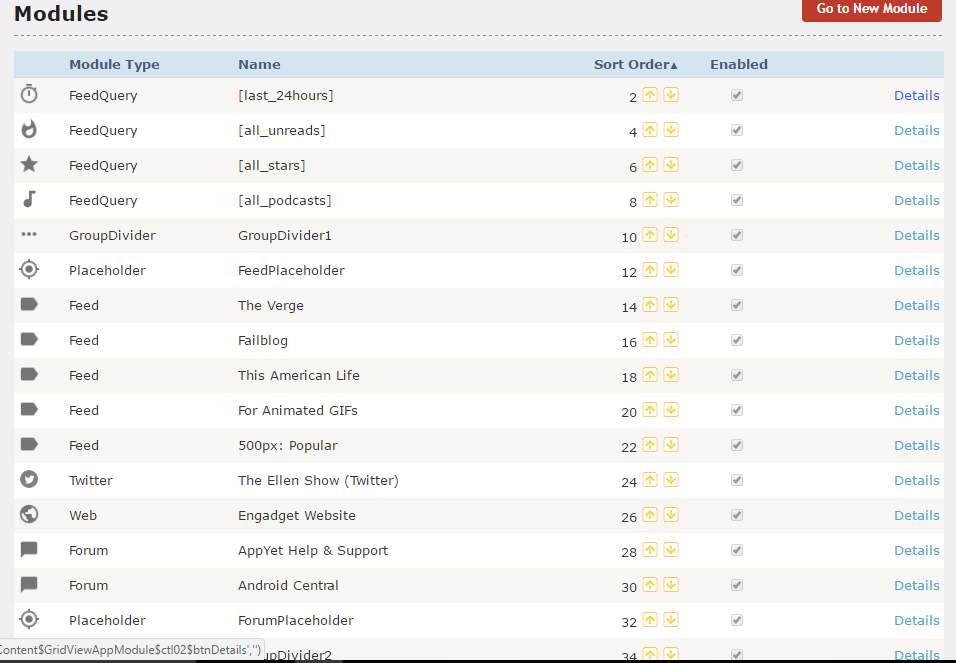
Figure 5.10
Now scroll to the bottom and uncheck the Enable and press save changes as in Figure 5.11.
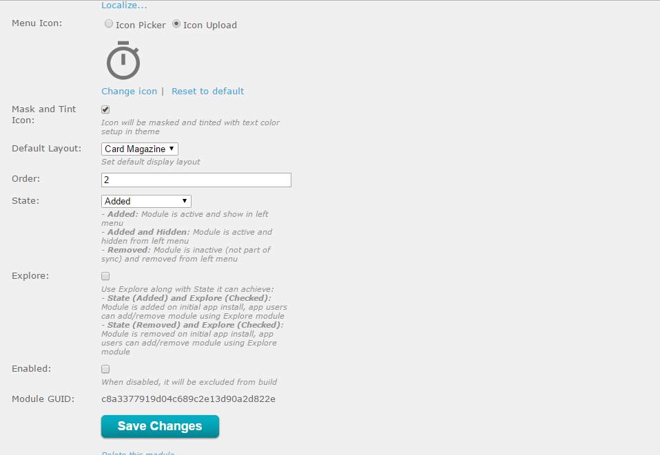
Figure 5.11
Now disable all the modules except web module.
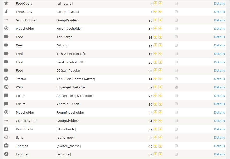
Figure 5.12
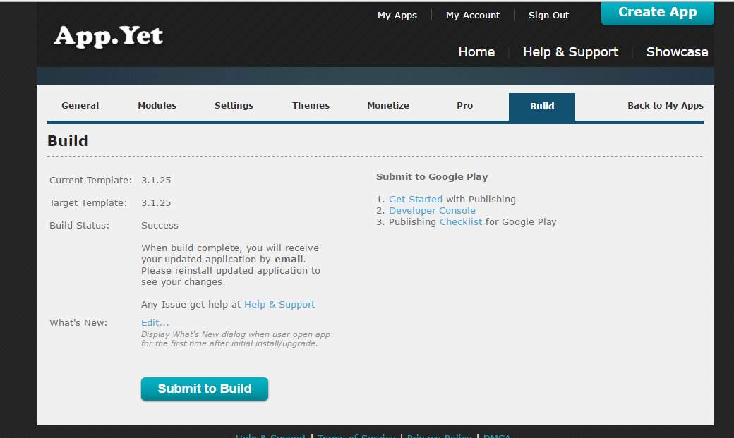
Figure 5.13
Now go to Build tab and click on Submit to build.
The app will be sent to the given email address
Now download the file and install it as shown in Figure 5.14.
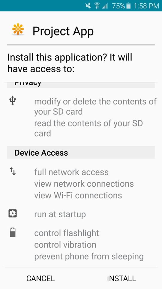
Figure 5.14
5.2.2 Raspberry pi auto login
The requirement in the project is to make Raspberry pi login and execute the script automatically after it finish up the boot process. To accomplish this certain settings needs to be done.
Raspberry pi asks for Login and password after booting
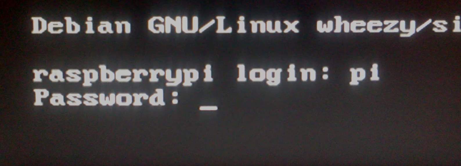
Figure 5.15
As a default raspberry pi login is pi and password is raspberry, But in order to execute python script in the start automatically raspberry pi should auto login.
In order to make raspberry pi auto login following steps should be followed.
After raspberry pi finish the boot type this command Sudo nano /etc/inittab
Now scroll down to the following command
1:2345:respawn:/sbin/getty –noclear 38400 tty1
Add # in the start of the command to make it comment as
#1:2345:respawn:/sbin/getty –noclear 38400 tty1
Now add this command underneath
1:2345:respawn:/bin/login -f pi tty1 /dev/tty1 2>&1
The file will look like as shown in Figure 5.16
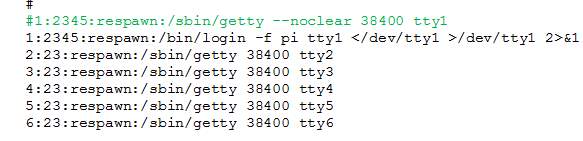
Figure 5.16
Save the file and exit [10].
Reboot raspberry pi and it will auto login.
5.2.3 Executing python script in start
Python script needs to be executed right after raspberry finishes its boot. To make certain script execute in the start follow the underlying steps.
After raspberry finish up the booting type Sudo nano /etc/rc.local
Now add the python file name and directory which is required to be executed before exit 0.
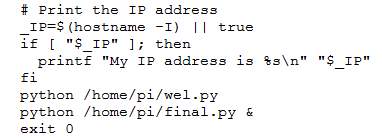
In this project 2 files are executing in the start.
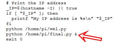
Do not forget to add “&” in the end of file directory otherwise raspberry pi will not reboot and will run in never ending loop [11]. Save and exit the file and reboot the raspberry pi, now it will execute the file right after the boot.
Chapter 6: Results
The aim of this project is to make the basic environmental factors accessible on internet which are vital for agriculture. To achieve this goal, standalone system has been planned and the most important was to make it power efficient. Power efficiency have been achieved in this project using effective programming. In this part of the project temperature and humidity has been obtained from the field using temperature and humidity sensors by interfacing it with microcontroller, this data serially communicated to RTU terminal of the Xbee pro.
After receiving the data at RTU end, RTU Encodes the data into API frame to make it secure and transmit to MTU of Xbee pro .The wireless communication results using Xbee pro has been observed with 100% success rate. MTU of Xbee pro is interfaced with Arduino microcontroller, which receives the data serially from MTU. Arduino is a central controlling device in this project, it is bringing in efficiency by carefully turning on and off devices which consumes high power.
Raspberry pi and Hotspot turbo stick are high power consumption devices. Raspberry pi is connected with Arduino microcontroller and communicates the data serially. Data received at Raspberry pi is encoded into API frame, Raspberry pi decodes the data and takes the desired data by picking up the right bits and combine them. In addition to that this data is also converted into humidity and temperature using formulas. This data then uploaded onto webservers, in this project www.data.sparkfun.com servers has been used as shown in Figure 6.1. It can store the data up to 100 Mb for free. The coding has been attached in Appendix.
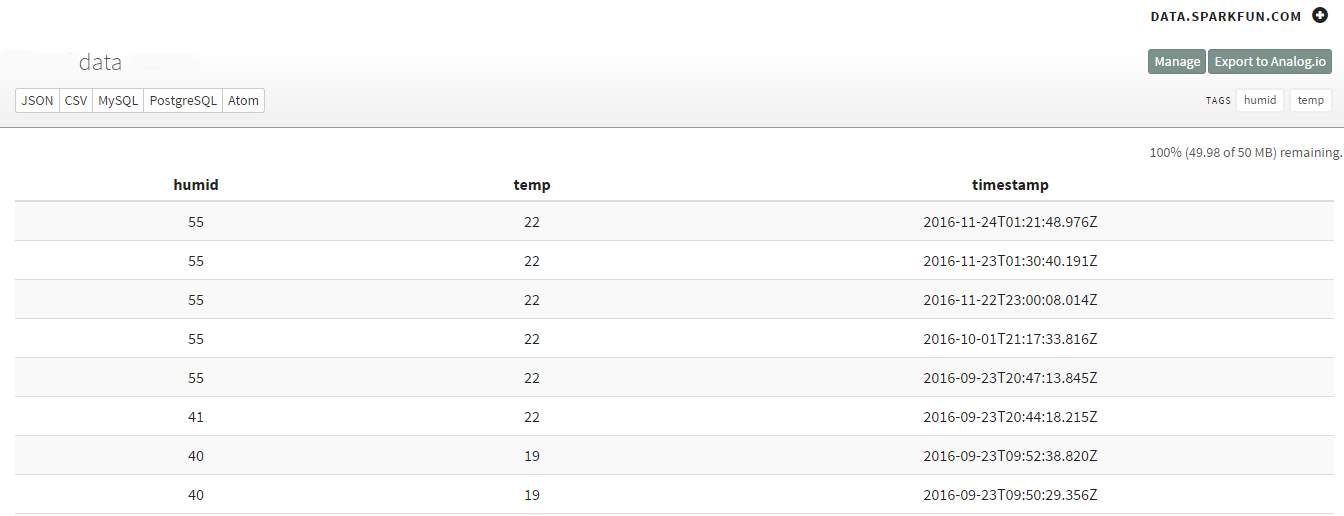
Figure 6.1 Data
In this part of project Humidity and temperature has been uploaded but more entities can be added by following the same method described in chapter 5. This data can be accessed from internet browser. Moreover, this data has been made more accessible by exhibiting on android app as shown in Figure 6.2.
6.1 Cost
The total costs of the devices used in this part of the project are less than 150$ which makes it extremely affordable. New models of raspberry pi has been flooded in the market after the success of its initial models but the raspberry used in this project can be bought for around $25.
The RF module used in this Project to communicate data is Xbee pro; Xbee pro has higher range than the regular models. The price of this module with its board is around $85.
Arduino mega 2560 has been used in the project it is equipped with 3 serial ports which makes it more preferred choice when it needs to communicate with more than one device. Arduino mega 2560 is a board equipped with microcontroller and besides all the qualities it is very cheap on price, it costs around $20.
Relay module has been used to provide the power to the raspberry pi and USB WI-FI hotspot stick. This relay module costs $5.
HUAWEI LTE E8372 Hotspot Turbo Stick is provided by the Bell network for free with a 2 year contract. TP-Link TL-WN725N has been used as USB WI-FI adapter and costs around $11.
6.2 Power consumption
6.2.1 Raspberry pi
The most power consuming device in this project is raspberry pi. Raspberry pi takes almost 1A current at 5V input. So in order to minimize the power usage in the project raspberry pi is left turned off until data needs to be uploaded to the webserver.
6.2.2 Xbee pro
Xbee pro power consumption is not high. It’s maximum when it is transmitting soar up to 250mA to 300mA. In hibernation mode its power depends upon SM selection as shown in Figure 6.1 [12].
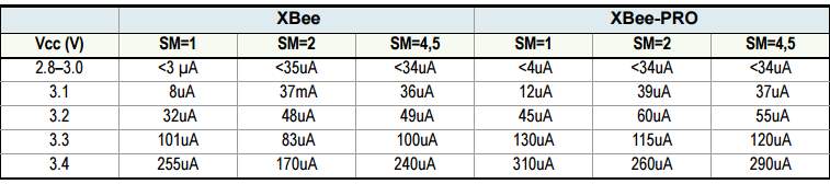
Figure 6.3 Xbee
6.2.3 Arduino Mega 2560
Arduino mega 2560 power consumption is very low. It operates at 5V and its output current limit on each pin is 20mA. The maximum current it can draw using all pins activated at single time would add up current to 800mA but in this project only 2 I/O pins have been used, so the total power consumption in this case is very low [13].
6.2.4 HUAWEI LTE E8372 Hotspot stick
This hotspot stick consumption is high, it operates at 5V and takes 750mA. Because of high power consumption, this device turns on along with raspberry pi only when data needs to be uploaded to the webserver [14].
Chapter 7: Conclusions and Future work
Population of world increasing by each passing day so the agricultural sector is under pressure to produce more than ever. More advanced approaches are now being practice to maximize the output of crops. A lot of research has been taking place to find out new and improved methods of agriculture. In this project, struggle have been made to increase the output of crops by monitoring the environmental factors carefully.
In this part of the project, two perimeters temperature and humidity have been successfully communicated and uploaded on to the internet. Furthermore, the project has been successfully made power efficient by effective programming. The cost of the project is the most critical part, so each device has been used in the project carefully chosen to serve the purpose and yet cheap on price.
For the future work, more aforementioned environmental factors will be added water level, sun light intensity, and wind speed. To make it stand alone system, Solar panel and battery backup will be installed. The selection of solar panel and battery backup will be critical so it can supply the power to the unit seamlessly.
The data uploaded to the server in this project is www.data.sparkfun.com this is free website but personnel and improved servers can be used to upload this data and by programming it can be achieved to send email if any of the environmental factor shows emergency situation. To transmit the data Xbee Pro RF module has been used but for more distant areas different devices can be chosen and design of directional antennas can accomplish extended range.
Appendix
Coding of Raspberry pi
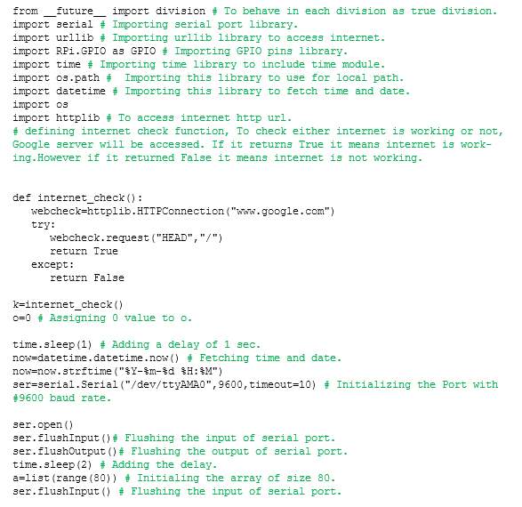
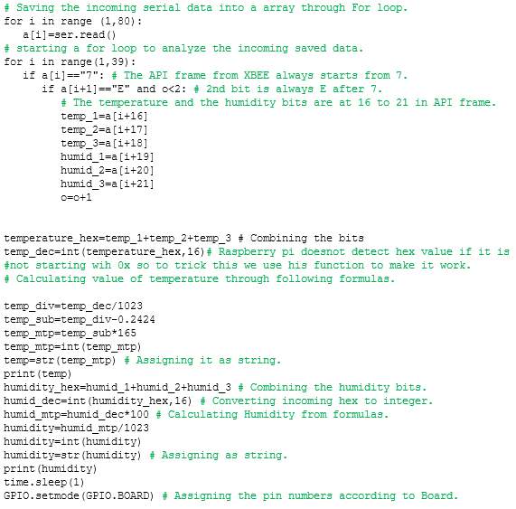
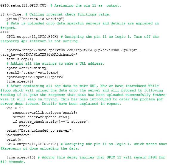
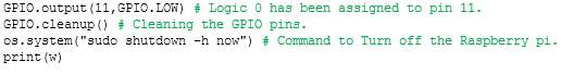
Each coding command has been explained in the comments. Comments have been mentioned in green color [15][16][17][18][19][20][21][22][23][24][25][26][27][28][29][30][31].
ARDUINO MEGA 2560
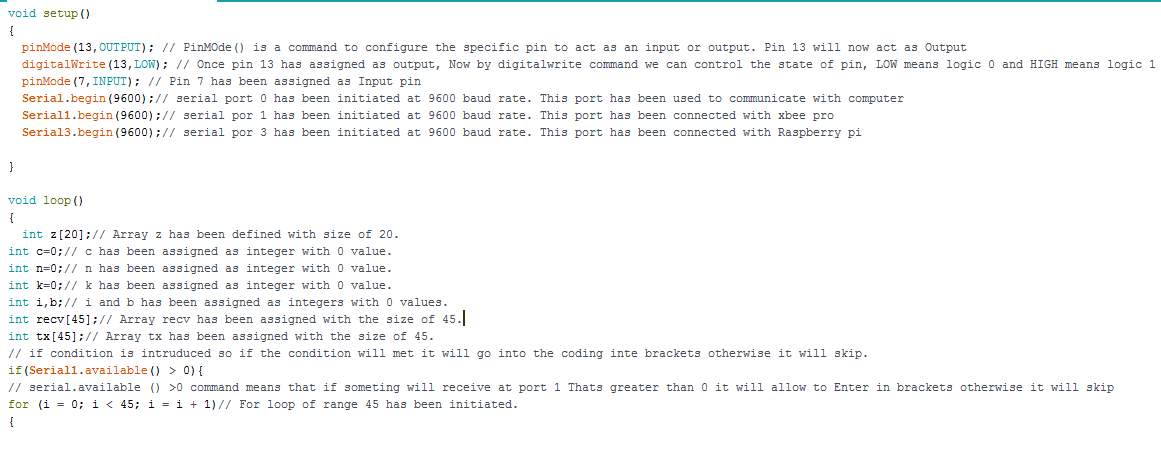
Each coding command has been explained in the comments.
if (z[n]==1 && z[n+1]==1 && z[n+15]==1 && k
This command has been used because while reading an input value at pin 7 from raspberry pi there has been a lot of garbage value being recorded, so to make it more resistant to floating values this condition has been introduced.
References
[1] “Estimates of population, Canada, provinces and territories”. Statistics Canada. December 18, 2013
[2] “The Effect of Temperature on Plant Growth”. June 1953.” Annual Review of Plant Physiology”. Vol. 4:347-362.
[3] E.-D. Schulze, R. H. Robichaux.(1987). “Plant Water Balance”. American Institute of Biological Sciences.DOI: 10.2307/1310175.
[4] Kopetz, Hermann. Real-time systems: design principles for distributed embedded applications. New York: Springer, 2011.
[5] Arouje, Sony. “Connecting XBee to Raspberry Pi – DZone IoT.” Dzone.com. October 24, 2016. Accessed May 12, 2017. https://dzone.com/articles/connecting-xbee-raspberry-pi.
[6] “Savage.home.automation.” SHA – – – Raspberry Pi – RS232 Serial Interface Options (Revisit). Accessed May 12, 2017. http://www.savagehomeautomation.com/projects/raspberry-pi-rs232-serial-interface-options-revisit.html.
[7] “Raspberry Pi and the Serial Port.” English Website. Accessed May 12, 2017. http://www.hobbytronics.co.uk/raspberry-pi-serial-port.
[8] Raspberry Pi • View topic – How to use serial TX/RX on GPIO?? Accessed May 12, 2017. https://www.raspberrypi.org/forums/viewtopic.php?f=44&t=97134.
[9] “Raspberry Pi and Arduino Connected Over Serial GPIO.” Oscar Liang. May 20, 2015. Accessed May 12, 2017. https://oscarliang.com/raspberry-pi-and-arduino-connected-serial-gpio/.
[10] “RPi Debian Auto Login.” RPi Debian Auto Login – eLinux.org. Accessed May 12, 2017. http://elinux.org/RPi_Debian_Auto_Login.
[11] “Rc.local.” Rc.local – Raspberry Pi Documentation. Accessed May 12, 2017. https://www.raspberrypi.org/documentation/linux/usage/rc-local.md.
[12]”XBee Datasheet” Accessed May 12, 2017. https://www.sparkfun.com/datasheets/Wireless/Zigbee/XBee-Datasheet.pdf
[13] Arduino – ArduinoBoardMega2560. Accessed May 12, 2017. https://www.arduino.cc/en/Main/ArduinoBoardMega2560.
[14]”Huawei Quick Start Guide”, Accessed May 12, 2017. https://images.wirelessdealer.ca/images/phones/userguide3967.pdf
[15] “1.10. Input and Output¶.” 1.10. Input and Output — Hands-on Python Tutorial for Python 3.1. Accessed May 12, 2017. http://anh.cs.luc.edu/python/hands-on/3.1/handsonHtml/io.html.
[16] “Reading data from external device.” Python – Reading data from external device – Raspberry Pi Stack Exchange. Accessed May 12, 2017. http://raspberrypi.stackexchange.com/questions/15615/reading-data-from-external-device.
[17] Raspberry Pi • View topic – simple serial port data logger. Accessed May 12, 2017. https://www.raspberrypi.org/forums/viewtopic.php?t=64545&p=644212.
[18] “Getting started with pySerial.” Zilogic Systems- Getting Started with pySerial. Accessed May 12, 2017. http://www.zilogic.com/blog/tutorial-pyserial.html.
[19] “Can’t Get Raspberry Pi and Xbee to Work Together.” Python – Can’t Get Raspberry Pi and Xbee to Work Together – Electrical Engineering Stack Exchange. Accessed May 13, 2017. http://electronics.stackexchange.com/questions/65263/cant-get-raspberry-pi-and-xbee-to-work-together.
[20] “PySerial and reading binary data.” Stack Overflow. Accessed May 13, 2017. http://stackoverflow.com/questions/7640993/pyserial-and-reading-binary-data.
[21] “How do I convert hex to decimal in Python?” How do I convert hex to decimal in Python? – Stack Overflow. Accessed May 13, 2017. http://stackoverflow.com/questions/9210525/how-do-i-convert-hex-to-decimal-in-python.
[22] “Hexadecimal string to byte array in python.” Bytearray – hexadecimal string to byte array in python – Stack Overflow. Accessed May 13, 2017. http://stackoverflow.com/questions/5649407/hexadecimal-string-to-byte-array-in-python.
[23] “Merge two integers in Python.” Stack Overflow. Accessed May 13, 2017. http://stackoverflow.com/questions/12838549/merge-two-integers-in-python. [24] “Calculating the Checksum of an API Packet.” Kb. Accessed May 13, 2017. http://knowledge.digi.com/articles/Knowledge_Base_Article/Calculating-the-Checksum-of-an-API-Packet.
[25] “Why doesn’t this division work in Python?” Numbers – Why doesn’t this division work in Python? – Stack Overflow. Accessed May 13, 2017. http://stackoverflow.com/questions/1787249/why-doesnt-this-division-work-in-python.
[26] “2. Built-in Functions¶.” 2. Built-in Functions — Python v3.1.5 documentation. Accessed May 13, 2017. https://docs.python.org/3.1/library/functions.html.
[27] “Convert hex string to int in Python.” Stack Overflow. Accessed May 13, 2017. http://stackoverflow.com/questions/209513/convert-hex-string-to-int-in-python.
[28] “Python integer to hexadecimal extra characters.” Hex – Python integer to hexadecimal extra characters – Stack Overflow. Accessed May 13, 2017. http://stackoverflow.com/questions/10218164/python-integer-to-hexadecimal-extra-characters.
[29] “How to open a url in python.” Bottle – how to open a url in python – Stack Overflow. Accessed May 13, 2017. http://stackoverflow.com/questions/4302027/how-to-open-a-url-in-python.
[30] MrLeeh. “Raspberry Pi Shutdown Button.” Instructables.com. May 12, 2016. Accessed May 13, 2017. http://www.instructables.com/id/Raspberry-Pi-Shutdown-Button/step4/Raspberry-Pi-Shutdown-script/.
[31] Gordons Projects. Accessed May 13, 2017. https://projects.drogon.net/raspberry-pi/gpio-examples/tux-crossing/gpio-examples-1-a-single-led/.
Figure references
“Raspberry Pi launched.” Visit timfrantic’s website. Accessed May 13, 2017. http://www.timrileydigital.com/phddiary/raspberry-pi-launched. /
Figure 2.1
http://computerlearnhow.com/wp-content/uploads/2012/05/Pi-diagram.jpg Figure 2.2
https://s-media-cache-ak0.pinimg.com/originals/95/30/46/953046f96aeb9ab53eb91abff2b24bc8.jpg Figure 2.3
https://refrobot.files.wordpress.com/2014/01/xbee-proc2ae-868z.jpg
Figure 2.4
http://pic-microcontroller.com/wp-content/uploads/2015/06/Interfacing-xbee-with-PIC-microcontroller-using-MikroC.jpg
Figure 2.5
https://svetelektro.com/Pictures/vf/xbee/uart_prenos.png
Figure 2.6
http://thomarmax.github.io/QtXBee/doc/pre_alpha/api-frame-escape-mode.png Figure 2.7
http://www.electroschematics.com/wp-content/uploads/2013/01/Arduino-Mega-2560-Pinout.jpg
Figure 2.8
https://www.google.ca/url?sa=i&rct=j&q=&esrc=s&source=images&cd=&ved=0ahUKEwjW2sWk3szQAhWh24MKHRXFDLMQjBwIBA&url=https%3A%2F%2Fforum.arduino.cc%2Findex.php%3Faction%3Ddlattach%3Btopic%3D125908.0%3Battach%3D26850&psig=AFQjCNE_kemofnmWCwpYWEAlgO0AyleXRA&ust=1480466618816568
Figure 2.9
http://support.bell.ca/Styles/wireless/all_languages/all_regions/catalog_images/large/mobile/front/Huawei_E8372_lrg1.png
Figure 2.10
http://brilliantlyeasy.com/wp-content/uploads/2014/03/linux_tl-wn725n-howto.jpg
Figure 2.11
http://www.buildyourowndrone.co.uk/media/catalog/product/cache/1/image/9df78eab33525d08d6e5fb8d27136e95/X/B/XBEE-RPSMA-2_2.jpg
Figure 3.1
http://artofcircuits.com/wp-content/uploads/2014/05/2-ch-relay-module-1.jpg Figure 3.5
http://42bots.com/wp-content/uploads/2015/03/GUI.jpg
Figure 4.1
http://static1.1.sqspcdn.com/static/f/1127462/20698433/1350791143717/serial-inittab.png?token=mNMa13YSBD0DL%2BEQ81VfhrioH1w%3D
Figure 4.2
https://www.google.ca/url?sa=i&rct=j&q=&esrc=s&source=images&cd=&ved=0ahUKEwjAm96p5czQAhXL1IMKHapwD60QjBwIBA&url=https%3A%2F%2Ffarm1.staticflickr.com%2F482%2F19919928911_4e5a3b05f7_o_d.png&psig=AFQjCNEjWzoqMQjXrWhz6E8mRND9CYGrTQ&ust=1480468557459608
Figure 4.3
https://www.google.ca/url?sa=i&rct=j&q=&esrc=s&source=images&cd=&ved=0ahUKEwjHyaza5szQAhUF3YMKHa9jCq0QjBwIBA&url=https%3A%2F%2Fwww.netsoup.net%2Fdocs%2Fraspberry-pi%2Fusage%2Fminecraft%2Fimages%2Fapp-menu-python2.png&psig=AFQjCNGsrWrReqMJcwzVPQFYMk-uCbzyrg&ust=1480468936779251
Figure 5.2
https://www.jeremymorgan.com/images/raspberry-pi-programming-python-1.png
Figure 5.3
https://www.jeremymorgan.com/images/raspberry-pi-programming-python-3.png
Figure 5.4
https://www.sparkfun.com/datasheets/Wireless/Zigbee/XBee-Manual.pdf
Figure 6.3
Table references
DIGI Xbee/Xbee- PRO 868 RF Module user guide
Table 2.1, Table 2.2.
Arduino Mega 2560 Data sheet by ManTech
Table 2.3
Cite This Work
To export a reference to this article please select a referencing stye below:
Related Services
View all


Related Content
All TagsContent relating to: "Farming"
Farming is the business or activity of working on a farm. Farming activities include ground preparations, sowing or planting seeds, tending crops, or activities involved in the raising of animals for meat or milk products.
Related Articles

DMCA / Removal Request
If you are the original writer of this dissertation and no longer wish to have your work published on the UKDiss.com website then please: