In-situ Strain Analysis of the Medial Collateral Ligament and Medial Meniscus with Anterior Cruciate Ligament Reconstruction
Info: 11098 words (44 pages) Dissertation
Published: 9th Dec 2019
Tagged: MedicalPhysiology
IN-SITU STRAIN ANALYSIS OF THE MEDIAL COLLATERAL LIGAMENT AND MEDIAL MENISCUS WITH ANTERIOR CRUCIATE LIGAMENT RECONSTRUCTION
1.0 introduction……………………………………………………..
2.0 background……………………………………………………..
2.1 anatomy of the knee……………………………………………
2.1.1 Anterior cruciate ligament………………………………….
2.1.2 Medial collateral ligament………………………………….
2.1.3 The menisci of the knee joint………………………………..
2.1.4 Other ligaments in the knee…………………………………
2.2 KNEE INJURIES……………………………………………..
2.2.1 Surgical treatment………………………………………..
2.2.2 Anterior cruciate ligament reconstruction………………………
2.2.3 Medial collateral ligament reconstruction……………………….
2.2.4 Graft choice…………………………………………….
3.0 LITERATURE REVIEW……………………………………………
3.1 material behavior of biological soft tissues……………………………
3.2 Biomechanical testing…………………………………………..
3.3 strain measurement……………………………………………
3.3.1 Strain gauges……………………………………………
3.3.2 Motion analysis………………………………………….
3.3.3 Digital image correlation……………………………………
3.3.4 Other methods of strain measurement…………………………
3.4 Finite element modeling…………………………………………
3.4.1 Constitutive laws…………………………………………
3.4.2 Modeling……………………………………………….
4.0 problem statement, aims, hypothesis, and outcomes………………………..
5.0 METHODOLOGY………………………………………………..
5.1 Aim 1: Strain on the native MCL and medial meniscus………………….
5.2 AIM 2: Strain on the grafts of the MCL reconstruction………………….
5.3 Preliminary results…………………………………………….
5.4 AIM 3: Finite element modeling…………………………………..
6.0 research plan…………………………………………………….
bibliography…………………………………………………………
1.0 introduction
Characterizing the mechanical behavior of biological soft tissues such as muscles, ligaments, and tendons remains challenging due to their composite, inhomogeneous structures. However, an understanding of the mechanical behavior of ligaments and tendons is imperative to understanding native ligament function and developing reconstruction techniques. The current understanding of ligament function in the knee joint is based largely on ligament cutting studies that have measured the change in laxity in the knee after a ligament was removed [57]. In this way, the anterior cruciate ligament (ACL) has been shown to be the primary restraint in the knee joint to anterior tibial translation and a secondary restraint to valgus rotation and internal rotation [16,99]. Similarly, the medial collateral ligament (MCL) has been shown to be the primary restraint to valgus rotation and a secondary restraint to anterior tibial translation and internal-external rotation [62,34,41,98,85,87,22].
Patients undergoing ACL reconstruction commonly have concomitant MCL injury, since the ACL and MCL fulfill similar kinematic functions, with one study estimating that this occurs in 24% of cases [68]. These combined ACL-MCL injuries compromise about 70% of all multiligamentous knee injuries [44]. Towards this end, further study is needed for treatment of both isolated and combined ACL-MCL injury. An understanding of the effects of ACL injury on the medial meniscus is also important because ACL injury has been shown to lead to tears and degeneration of the medial meniscus [32]. As yet, very few studies have provided rigorous in situ analysis of ligaments that includes strain and deformation. The main purpose of this study is to use a high-resolution experimental strain measurement technique to measure in situ strain on the surface of the MCL and medial meniscus during physiological knee loading, in order to study the native knee as well as combined ACL-MCL injury.
2.0 background
2.1 anatomy of the knee
The knee joint is a synovial hinge joint formed between the femur, tibia, fibula and patella with two crescent-shaped fibrocartilage pads, known as the menisci, located between the femur and tibia. The knee joint is made up of a complex system of ligaments that work to guide the motion of the knee [49]. The four major ligaments of the human knee are the anterior cruciate ligament (ACL), posterior cruciate ligament (PCL), medial collateral ligament (MCL), and lateral collateral ligament (LCL). An illustration of the knee joint is shown in Figure 1.
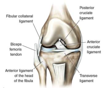
Figure 1. Illustration of the knee joint [8].
2.1.1 Anterior cruciate ligament
Studies have described the ACL as having an hourglass shape [27,36,66], where its cross-sectional area and shape are dependent on the physiological tension and joint angle (flexion angle) of the knee [27]. The ACL is one of the major stabilizers of the knee joint, providing primary restraint to anterior tibial translation (ATT) [16,99]. The ACL also provides restraint to valgus and internal tibial rotation, as well and knee hyperextension [99]. The ACL has been described as consisting of two bundles, which are named according to their insertion sites on tibial plateau: the anteromedial bundle and posterolateral bundle [102], as shown in Figure 2.
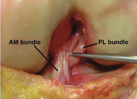
Figure 2. AM and PL bundle of ACL [37].
2.1.2 Medial collateral ligament
The medial collateral ligament (MCL) has been described as a broad, flat band [96] which connects the femur to the tibia and has attachments to the medial meniscus. However, the current understanding of the MCL morphology is largely based on anatomic studies that have been done under dissection, neglecting the effects of physiological tension and joint angle of the knee [56,17,92,5,80,52]. The MCL is the primary stabilizer against valgus rotation in the knee joint, and a secondary restraint to anterior tibial translation, and internal-external tibial rotation [62,34,41,98,85,87,22].
Authors have described the MCL as complex on the medial side of the knee (Figure 3), consisting of the superficial MCL (sMCL), the deep MCL (dMCL), and the posterior oblique ligament (POL) [52,81]. In the MCL complex, the sMCL and POL have unique contributions to load transfer across the knee joint [91,34,35,73]. The sMCL provides the greatest stability to valgus forces over the entire range of motion, and the contribution of the sMCL to internal rotation stability increases beyond 30° of knee flexion. The POL provides secondary stability to internal and external tibial rotation at low knee flexion angles. The dMCL makes almost no contribution to medial stability.
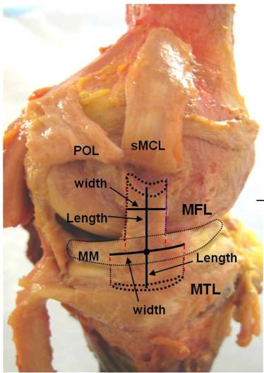
Figure 3. MCL complex showing sMCL, POL and dMCL [56].
2.1.3 The menisci of the knee joint
There are two menisci in each knee joint, namely the lateral and the medial meniscus. The menisci work to disperse the weight from the body over onto the tibia, and work to reduce friction from motion of the femur on the tibia during flexion-extension of the knee [38]. The menisci attach to various major ligaments in the knee joint. Briefly, the medial meniscus is attached to the deep layer of the MCL. The transverse ligament connects the anterior horn of the lateral meniscus to the anterior horn of the medial meniscus, the menisco-tibial ligaments (also called the coronary ligaments of the knee) connect the inferior edges of the menisci to the tibia, and the menisco-femoral ligaments (also called the ligaments of Humphrey and Wrisberg) connect the posterior horn of the lateral meniscus to the lateral aspect of the medial femoral condyle [31].
2.1.4 Other ligaments in the knee
Apart from the ACL and MCL, the other major ligaments in the human knee are the PCL, MCL and LCL. The PCL is the principal restraint against posterior tibial translation [61,54]. The LCL is located on the lateral side of the knee joint, connects the femur to the fibula, and is the primary stabilizer against varus rotation in the knee joint [65].
2.2 KNEE INJURIES
Ligament injuries can occur in isolation or concomitant with other ligaments, which is the case with multiple ligament injury. Injured ligaments are called sprains, and are generally graded on the following scale (Figure 4):
- Grade I – the ligament is slightly stretched, but the joint is still stable.
- Grade II – the ligament is stretched or partially torn, and the joint is somewhat unstable.
- Grade III – the ligament is completely torn, and the joint is unstable.
ACL injury has been well studied in the literature because it is one of the most common sports injuries with approximately 100,000 ACL reconstructions performed each year in the United States [12]. ACL injury often occurs in sports accidents, but may also occur in other situations such as a vehicular accident. The mechanism of ACL injury has been suggested as deceleration combined with cutting, pivoting, sidestepping maneuvers, or hard landings [101,33]. Studies estimate that 70% of ACL injuries result through non-contact mechanisms, and that 30% result through contact with another player (in sports injuries) or an object [33].
Patients undergoing ACL reconstruction commonly have concomitant MCL injury, since the ACL and MCL fulfill similar kinematic functions, with one study estimating that this occurs in 24% of cases [68]. These combined ACL-MCL injuries compromise about 70% of all multiligamentous knee injuries [44]. Towards this end, further study is needed because fundamental questions regarding the role of the ACL and MCL as well as the efficacy of reconstruction procedures still exist. It is important to note that an MCL injury means that the entire MCL complex is affected. Similar to ACL injury, MCL injury often results from sports accidents. MCL injury typically occurs with valgus knee loading, which is common in sports such as ice hockey, skiing, and football [74].
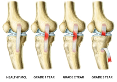
Figure 4. Grading of MCL injuries [1].
Patients undergoing ACL reconstruction may also have concomitant meniscal injury with a prevalence of 55% to 65% [23]. In patients with acute ACL injury, lateral meniscus tears occur more frequently than do medial meniscus tears; however, in patients with chronic ACL-deficient knees, medial meniscus tears are more frequent [32].
2.2.1 Surgical treatment
Treatment of knee injuries is generally dependent on a variety of factors, including the severity of the sprain the needs of the patient.
2.2.2 Anterior cruciate ligament reconstruction
Generally, a torn ACL (Grade III) will not heal, due to the avascular nature of the ACL, and will require surgical reconstruction to regain stability of the knee joint [11]. ACL reconstruction is referred to as anatomic if the position of the graft matches the position of the native ACL insertion site, and non-anatomic if the position of the graft does not match the position of the native ACL insertion site, as is the case with transtibial ACL reconstruction. Historically, transtibial reconstruction has been used in ACL reconstruction in which the ACL femoral tunnel is drilled through from the tibial tunnel. However, in recent years anatomic ACL reconstruction has gained favor in the clinical community. The goals of anatomic ACL reconstruction are the restoration of the native ACL’s dimensions, collagen orientations, and insertion sites [89]. Placement of the tunnels in their anatomic positions has been shown to better restore knee kinematics and stability, improving functional outcomes and potentially slowing long-term joint degradation [82].
2.2.3 Medial collateral ligament reconstruction
In contrast to the ACL, the MCL has shown to have a good healing capacity in both animal and clinical studies [11]. However, the biomechanical properties of the healing MCL fail to return to that of the uninjured MCL [97] especially when combined with ACL injury [98]. Generally, non-operative treatment is recommended for Grade I and Grade II injuries and operative treatment may be recommended for Grade III injuries if non-operative treatment does not lead to an improvement in knee stability. There is no consensus in the clinical community regarding the treatment of combined ACL and MCL injuries with some studies suggesting that the ACL should be treated operatively while the MCL should be treated non-operatively [4,30,60].
There have been a variety of techniques proposed for reconstruction of the MCL in the literature, however, anatomic techniques, where the femoral and tibial tunnels are placed over the native insertion sites will be the focus of this work. There have been two anatomic MCL reconstructions proposed: single-bundle and double-bundle MCL reconstruction. In single-bundle MCL reconstruction, a single graft is used to reconstruct the sMCL [63]. In double-bundle MCL reconstruction, two separate grafts are used to reconstruct the both the sMCL as well as the POL [9] and thus restore the entire MCL anatomy. Both reconstructions are shown in Figure 5.
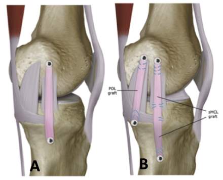
Figure 5. A) Single-bundle MCL reconstruction, and B) double-bundle MCL reconstruction [18].
2.2.4 Graft choice
When a ligament is surgically reconstructed, some kind of graft will be used. The ideal graft material used for reconstruction should reproduce the complex anatomy of the native ligament, provide similar biomechanical properties of the native ligament, promote biological incorporation, and minimize donor site morbidity (if an autogenous graft is used). However, no single graft source meets all of the above criteria [67,24]. Commonly used autogenous grafts include bone-patella-tendon-bone (BPTB), quadrupled hamstring and quadriceps tendon (with or without bone). Commonly used allograft options include BPTB, hamstring tendon, Achilles tendon, and anterior or posterior tibialis tendon.
3.0 LITERATURE REVIEW
3.1 material behavior of biological soft tissues
Biological soft tissues are composite materials typically made up of a combination of collagen and elastin fibers arranged in a matrix of other substances, including hydrophilic glycosaminoglycan molecules [13]. Tissues with large proportion of hydrophilic components have high water contents. Structurally, ligaments are composed of a collagen fibers embedded in ground substance matrix of proteoglycans, glycolipids and water where the fiber orientation represents is generally described as being aligned with the long axis of the ligament [105]. The collagen fibers provide resistance to tensile loading but provide negligible resistance to compressive loading [95]. In addition to the non-linear elastic response, ligaments may exhibit time and history dependent visco-elastic properties that arise from the interaction between the water and the ground substance matrix.
Multiaxial material property data in the longitudinal and transverse fiber direction was presented by Quapp and Weiss [77], as shown in Figure 6. In this study, nine specimens were used to calculate the average longitudinal material properties while seven specimens were used to calculate the average transverse material properties. The stress-strain curve of this study represent the typical behavior of the stress-strain curves of ligamentous tissue. Briefly, the non-linear stress-strain curves of ligaments have three major regions: 1) the toe region, 2) the linear region, and 3) the yield and failure region. The toe region represents an “uncrimping” of the collagen fibers, where the fibers are being recruited. As the collagen fibers become uncrimped, the collagen fibers reinforce the ligament and the ligament becomes stiffer. When a critical stretch is reached all and all fibers are recruited the stress-strain behavior becomes linear. As individual fibers within the ligament begin to fail, stiffness is reduced and the ligament begins to fail [14].
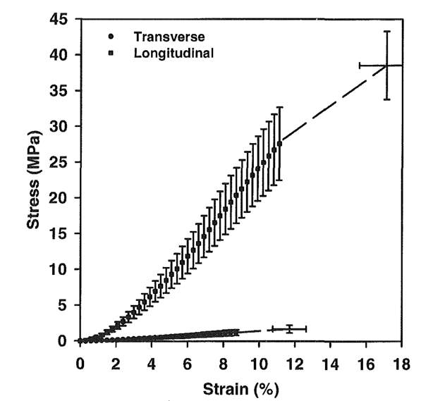
Figure 6. Stress-strain curve for human MCL along the longitudinal and transverse collagen fiber direction [78].
3.2 Biomechanical testing
There has been biomechanical study regarding combined ACL-MCL injury. Cadaver studies have concluded that valgus laxity is relatively unaffected by ACL deficiency [34,62,57], however, anteroposterior laxity and internal rotational laxity was significantly increased by ACL deficiency [57]. Furthermore, ACL deficiency has been shown to caused an increase the forces in the MCL during anterior tibial and internal rotational loading [57]. Inoue et al. [42] found that valgus laxity was unaffected by an MCL tear because the deficit was mainly compensated for by the ACL. Battaglia et al. [7] found that partial and complete MCL tears significantly increased the force in the ACL during valgus and internal rotational loading. Mazzocca et al. [64] concluded that insolated Grade III MCL injuries can compromise the ACL. These findings suggest that the overlapping function of the ACL and the MCL may cause the injury of one ligament to affect the other; however, further study regarding combined injury is needed to reach a definitive conclusion.
The importance of the medial meniscus as a secondary restraint to anterior-posterior translation of the tibia in the ACL-deficient knee has also been presented in the literature [53,62,86]. Insufficiency of the ACL has been shown to increase the forces on the medial meniscus [2] and thus predisposes patients to meniscal tears [32]. Papageorgiou et al. [69] suggested that the interdependence between the ACL and the medial meniscus is so substantial that the loss of one structure could predispose the other to injury.
3.3 strain measurement
Soft tissues are composite structures, inhomogeneous, and undergo multi-directional loading so it is important to obtain full-field measurement of strain in these kinds of materials. The composite nature and high water content of soft tissues poses challenges for strain measurement. For example, the elastic fibers in soft tissues cause them to be flexible and deform extensively even under small forces which means that methods that contact the surface can introduce inaccuracy in strain measurement. Furthermore, the high water content of soft tissues can cause dehydration when the tissue is exposed for strain measurement, which in turn could alter the properties of the soft tissue under examination.
3.3.1 Strain gauges
Several types of strain gauges have been used in strain studies of soft tissue in the literature, however, strain gauges require some form of fixation to the tissue thereby potentially introducing measurement errors [79]. Furthermore, strain gauges will have very limited resolution so visualization of the strain field will not be possible. Hull et al. [40] used mercury strain gauges to measure strain at four sites in the human MCL. They found a significant interaction between the site experiencing the greatest strain and the flexion angle under physiological loading. Bates et al. [6] used differential variable resistance transducers (DVRT), implanted on the ACL and MCL, to measure strain in the ACL and MCL during simulated jump landing and sidestep cutting tasks. They found that during the simulated athletic tasks, the ACL provides greater contributions to knee restraint than the MCL. Hollis et al. [39] used DVRT’s, implanted in two sites on both the lateral and medial menisci (Figure 7), to measure the change in meniscal strain with ACL injury and ACL reconstruction with an anterior-posterior tibial load. They found that a statistically significant increase in meniscal strain in the ligament-transected knees compared to the intact knees; however, ACL reconstruction led to a reduction in the meniscal strain to a level similar to the intact knee. Seitz et al. [84] conducted a study to measure the effect of partial meniscectomy on meniscal hoop strain under compressive loading, and Jones et al. [43] conducted a study to measure the effect of a torn medial meniscus on hoop strain under compressive loading; however, compression loading is not the focus of this study.
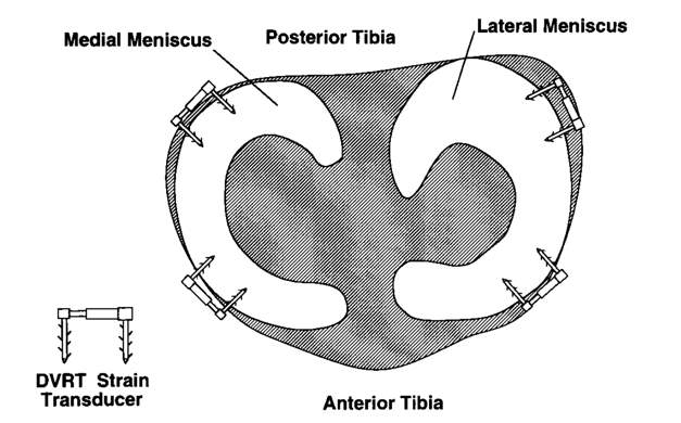
Figure 7. Strain gauges placed on the menisci [39].
3.3.2 Motion analysis
Studies have used 3-D motion analysis to measure strain simultaneously at multiple locations on the surface of soft tissue [57,22,29]. Briefly, the 3-D coordinates of fiducial markers, which are usually small round beads, are placed on the surface of soft tissue and are tracked during deformation as shown in Figure 8. The fiducial makers can be placed along the local fiber direction. A frame with fiducial markers is used to calibrate the system, where the distance between the markers has been very accurately measured. The tensile strain between the marker pairs can be calculated from the lengths between markers pairs in the reference state and during each experimental conditions, assuming that the deformation between marker pairs is homogeneous. In this way transverse or shear strains are not measured. To aid in the visualization of the results, the strain can be interpolated onto a mesh. However, this method may lack resolution and accuracy [59].
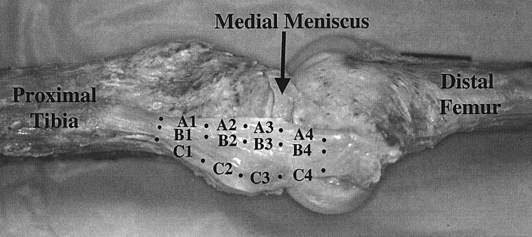
Figure 8. Fiducial markers placed on the surface of the MCL [29]
Gardiner et al. [29] tested the native knee and found that the highest strains in the MCL were found at full extension on the posterior side of the MCL, which correlate with clinical findings of the locations of MCL injuries. Lujan et al. [57] found that in the ACL deficient knee, the strain in MCL ligament fibers are relatively unaffected compared to the native knee during valgus rotation, however, the strain significantly increased compared to the native knee during ATT and are raised to levels of microtrauma. Neither study considered any surgical reconstruction of the ACL or MCL, nor did they measure strain in the medial meniscus.
3.3.3 Digital image correlation
Digital image correlation (DIC) is a non-contact, optical strain measurement technique that is widely accepted and commonly used in the field of experimental mechanics with 2-D and 3-D application, where 3-D DIC provides full-field displacement and the strain tensor on the test specimen’s surface. The basic principle of DIC, shown in Figure 9 [55], illustrates a 2-D mapping of points from the references image to the deformed image. Briefly, a computer algorithm tracks points on the surface of an object between the reference image (before loading) and the deformed image (after loading) in order to match subsets of the two images [55]. The algorithm defines unique correlation areas known as micro-image facets, typically a 5-20 pixel square, across the test samples surface. Each facet is a measurement point that is tracked in each successive image with sub-pixel accuracy [58]. In this way, a high-resolution map of the displacement and strain fields of the entire surface of the object can be obtained. Typically, a random speckle pattern is applied to the surface of the test sample before testing. The speckle pattern needs to have a high contrast so it is usually black speckles on a white background, or vice versa. The use of one camera allows for single plane (2-D) measurements, whereas the introduction of a second camera allows two images of the same object to be captured at two different angles to allow 3-D measurements [58].
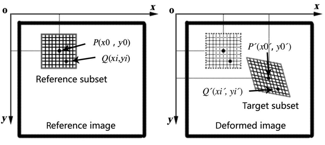
Figure 9. 2-D mapping of points P and Q in reference image to p and q in deformed image [55].
Since DIC is a non-contact strain measurement technique, it bears the advantage of not requiring contact with the surface of the material. This is a major advantage over contact strain measurement techniques, such as strain gauges, which usually require adhesion to the surface of the test specimen. 3-D DIC can also provide a high-resolution full-field strain analysis of the surface, which enables visualization of multidirectional strain components that would not be possible with strain gauges [58]. Another advantage of 3-D DIC is that it is directly comparable to finite element models for model verification [58]. When used as the manufacturer recommends, 3-D DIC is a powerful tool that has a high strain resolution of 20 microstrain, a strain range from 0.005% to greater than 2,000%, and full-field measurement of 3-D coordinates, 3-D displacements, 3-D velocities, and the strain tensor, according to the manufacturer. The 3-D DIC system utilizes calibration grids to calibrate coordinates, displacement and velocities within the cameras field of view. Both the overall ligament strains and the local strains in the ligament can be measured with the DIC system.
Luyckx et al. [58] compared longitudinal strain measurements from 3-D DIC to linear variable differential transformers (LVDT’s), which measure linear displacement with an accuracy of 1 μm, on six samples of human Achilles tendon. They found that the correlation coefficient between the measurements showed excellent linear agreement in all specimens that they tested (R2=0.99), thus, 3-D DIC has comparable accuracy to LVDT’s in determining longitudinal strain. An example of specimen preparation and the strain map obtained by placing a tensile load on human tendon using a DIC system is shown in Figure 10, which is taken from Luyckx et al. [58]. Luyckx et al. reported a spatial resolution (0.1 mm2) for strain measurements on the tendon.
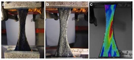
Figure 10. Tendon in clamps, a) dyed with methylene blue, b) speckled with white paint, and c) 3D DIC strain map plotted on the specimen showing the longitudinal strain [58].
While DIC has widely been used in the field of experimental mechanics for strain and displacement measurements, the use of this technique with biological soft tissues is more limited. DIC has been used to analyze strain in arterial tissue [103], bovine cornea [10], cartilage [104], and bone [20,19,88]. Luyckx et al. [59] has used DIC to analyze the strain and deformation of the sMCL in the native knee during range of motion as shown in Figure 11. They found that the deformation created strains that were significantly higher at the femoral insertion site of the sMCL. However, their study did not consider physiological knee loading or any surgical reconstruction, nor did they measure strain in the medial meniscus.
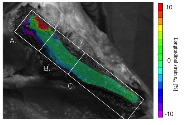
Figure 11. Regional strain distribution in the sMCL during range of motion (A: proximal, B: middle, C: distal) [59].
3.3.4 Other methods of strain measurement
Kawada et al. [48] used a photoelastic coating film to measure the strain distribution over the entire MCL surface. Their approach utilized a polyurethane monomer as a photoelastic coating film, and they confirmed through their study that this film had a high sensitivity for strain and a good adhesion to the ligament. They tested the MCL to failure in both simple tension and valgus loading. In simple tension, they found that the strain concentrations were centered at the tibial insertion site, which is also where the specimens ruptured. With application of valgus loading, they found increased strain in the MCL from the medial femoral condyle to the medial epicondyle, and histological analysis demonstrated midsubstance ligament ruptures in the same region.
3.4 Finite element modeling
The rise of computational methods for the study of joint mechanics has gained popularity in recent years because of the cost and challenges associated with studying human joints and ligaments. In terms of computational methods, the finite element method offers the ability to predict spatial and temporal variations in stress, strain and contact area/forces [94]. However, finite element modeling of ligament behavior is complicated by non-linear and viscous material behavior as well as complex geometry, initial conditions, boundary conditions and loading conditions.
3.4.1 Constitutive laws
Constitutive equations are used to describe the stress-strain behavior of materials through specification of the dependence of stress on parameters such as the deformation gradient, rate of deformation, etc. Table 1 gives a summary of the constitutive laws used in finite element modeling of the MCL in the literature.
Table 1. Summary of constitutive laws used to model the MCL.
| Author | Model | Material |
| Veronda, 1970 [90] | Mathematical and experimental | Skin (exponential strain energy function) |
| Lanir, 1983 [50] | Mathematical | Fibrous tissue (fiber-reinforced, incompressible, hyperelastic) |
| Weiss, 1996 [95] | Mathematical | Ligament and tendon (fiber-reinforced, incompressible, transversely isotropic, hyperelastic) |
| Pioletti, 1997 [76] | Mathematical and experimental | Ligament and tendon (isotropic, incompressible, visco-elastic) |
One approach to describe the material behavior of ligaments and tendons is called the phenomenological approach, where mathematical equations are fitted to experimentally obtained stress-strain behavior. Using this approach, Pioletti et al. [76] presented an isotropic, visco-elastic constitutive model for ligaments where the strain energy function was split into a viscous potential,
Wv
, in conjunction with an elastic potential,
We
, developed by Veronda and Westmann [90] as follows
We=αeβ(I1-3)+C1I2-3,
(1)
Wv=η4J2I1-3,
(2)
where η is the viscous parameter; (α, β) are elastic parameters and
C1=-αβ2
;
I1
is the first strain invariant;
I2
is the second strain invariant; and
J2
is the second strain rate invariant. A least-squares fit of the experimentally obtained stress-strain curves furnishes the values of the parameters (α, β, η). The major limitation of this model is the assumption of isotropy. This constitutive law has been used to model the ligaments and tendon in the human knee (ACL, PCL and patella tendon) [76] and the ACL [75].
While there have been experimental studies conducted in the investigation of the visco-elastic properties of ligaments and tendons [76,70,21,15], ligaments and tendons reach a pre-conditioned state after repeated loadings so there is minimal amount of hysteresis [93]. Thus, the inclusion of visco-elastic properties is often neglected in finite element studies of soft tissue, with the focus set on the quasi-static non-linear elastic response of the tissue.
The theoretical understanding of ligament mechanics has advanced in recent decades, so some researchers have developed structural constitutive models which take into account the tissue components, geometry, and interactions. In this way, structural models are able to incorporate the non-linearity, anisotropy, and incompressibility of the soft tissue. Thus, the structural models can help elucidate the role of individual components in the gross mechanical response of the tissue.
Lanir [50] proposed a 3-dimensional model for fiber-reinforced collagenous tissues that described the stress in the ligament as a function of the tensile stretch in the collagen fibers with a hydrostatic pressure that arises from the ground substance matrix. The Lanir model assumed that the entire stress was placed on the collagen fibers, the ligament did not support a compressive load, and that the unfolding of the fibers during deformation resulted in an internal hydrostatic pressure because the fibers squeezed the ground matrix. The Cauchy stress is then given by
σ=λWλa ⊗ a+pI
, (3)
where
λ
is the stretch ratio;
Wk
is the strain energy derivative with respect to
λ
; a is a unit vector field representing the fiber direction in the deformed configuration; and p is a hydrostatic pressure from the incompressible ground substance matrix. Note that this model includes only one family of fibers that are usually assumed to be in the longitudinal direction of the ligament [105]. While this model provides a hyperelastic, 3-dimenstional, anisotropic description of the quasi-static behavior of tissue, the major limitation of this model is that the entire stress will be carried by the collagen fibers if it is fitted to uniaxial tensile data.
Using the approach of Lanir [51] that described the stress in the ligament as a function of the tensile stretch in the collagen fibers, Weiss et al. [95] developed a transversely isotropic, hyperelastic material, where the strain energy function is split into a contribution from the collagen fibers
F1
, ground substance matrix
F2
, and the interaction
F3
as follows
W=F1I1, I2+ F2λ+ F3I1,I2,λ.
(4)
Weiss [95,77] has presented two models for the ground substance. The first model describes the ground substance matrix using the Neo-Hookean material model, given as
F1=C12I1-3
. (5)
The second model describes the ground substance matrix using the Mooney-Rivlin material model, given as
F1=C12I1-3+C22I2-3
, (6)
where
C1
and
C2
are material parameters that governs the mechanical response of the ground substance. The strain energy of the fiber can defined as a function of the fiber stretch as follows [95]
λWλ=0
,
λ<1;
λWλ=C3eC4(λ-1)-1
,
1<λ <λ*;
(7)
λWλ=C5λ+C6
,
λ≥λ*.
where the
C3- C6
are material parameters that governs the mechanical response of the collagen fibers;
λ
is the stretch along the collagen fiber direction;
Wk
is the strain energy derivative with respect to
λ
; and
λ*
is the stretch value when the collagen fibers are straightened. The Cauchy stress can then be written as
σ=2W1+I1W2B-W2B2+λWλa⊗a+pI
, (8)
where B is the left deformation tensor;
W1
and
W2
are the strain energy derivatives with respect to
I1
and
I2
, respectively; and
Wk
is the strain energy derivative with respect to
λ
given in Eq. 7.
3.4.2 Modeling
Finite element models of the MCL have been presented in the literature. Gardiner and Weiss [28] developed subject-specific finite element models of eight human male knees using the transversely isotropic hyperelastic material model [95] to represent the MCL, with a the ground substance matrix described as a Neo-Hookean material. They also used subject-specific bone and ligament geometry, material properties, and joint kinematics. Bone and ligament geometry was taken from CT images, and the bones were treated as rigid. Displacement boundary conditions were imported into the model from a robotic testing system where a 10 Nm valgus torque was applied at various knee flexion angles. The initial strains in the ligament were estimated by measuring the strain on the surface of the ligament after the ligament had been removed from the bone and allowed to relax in a saline solution to achieve a stress-free state. Despite large inter-subject variation in MCL material properties, MCL strain distributions predicted by individual finite element models that used averaged material properties were strongly correlated with subject-specific finite element strain predictions (R2=0.99 at all knee flexion angles) [28].
Pena et al. [71] developed a finite element model of a healthy knee joint using subject-specific geometry of the bones, MCL, LCL, ACL, PCL, patella tendon, menisci and articular cartilage obtained from an MRI. They used subject specific kinematics, obtained from a robotic testing system, where a combined compressive load of 1150 N and anterior tibial load of 134 N was applied to the joint at various knee flexion angles. They modeled the ligaments as transversely isotropic hyperelastic [95], treated the bones as rigid, and used averaged material parameters and initial strain estimates taken from the literature. Similar approaches in finite element modeling have also been used in various other finite element studies of the MCL [22,57,71].
Finite element models of the grafts of knee ligaments have also been presented in the literature. Pena et al. [72] developed a finite element model of the ACL graft in order to study the effect of graft stiffness and graft tensioning in ACL reconstruction. The geometry of the bones was obtained with MRI, and grafts were modeled as a cylinder. They used subject specific kinematics, obtained from a robotic testing system, where a combined compressive load of 134 N was applied to the joint at various knee flexion angles. The MCL, LCL, ACL, PCL, and patella tendon were included in the model while the menisci and articular cartilages were left out. The ligaments and the graft were modeled with a transversely isotropic hyperelastic material [95] with a Neo-Hookean ground substance. Averaged material parameters and estimates of initial strain taken from the literature. The bones were treated as rigid. The initial graft tension was set to 0, 20, 40, and 60 N and three different values of stiffness were used corresponding to those of the patella tendon, gracilis and quadrupled semitendinosus grafts.
Bae et al. [3] developed a finite element model of the contact pressure between the ACL graft and bone, where the maximum principal stresses in the grafts were calculated. The geometry of the bones was obtained from a CT scan. They used subject specific kinematics, obtained from flexing the knee from full extension to 90° of knee flexion. The graft was modeled as a cylinder with a transversely isotropic hyperelastic material model [95], the bones were treated as rigid, and an initial tension of 44 N was applied to the graft. Averaged material parameters were taken from the literature.
4.0 problem statement, aims, hypothesis, and outcomes
In the MCL complex, the sMCL and POL have unique contributions to load transfer across the knee joint, however, a rigorous in situ analysis of these individual structures has not been provided that includes strain and deformation. Furthermore, the mechanical functions of ligaments are often interrelated [57], so an understanding of ligament mechanical behavior is important in regards to multiligamentous injuries as in the case of combined ACL-MCL injury. Similarly, an understanding of the effects of ACL injury on the medial meniscus is also important because ACL injury has been shown to lead to tears and degeneration of the medial meniscus [32].
The main purpose of this study is to use a high-resolution experimental strain measurement technique to measure in situ strain on the surface of the MCL and medial meniscus during physiological knee loading, in order to study the native knee as well as combined ACL-MCL injury. The specific aims and hypotheses of this work are as follows:
Aim 1: Strain on the native MCL and medial meniscus.
Determine the in situ strain patterns on the surface of the native MCL complex (sMCL and POL) and the anterior aspect of the peripheral surface of the medial meniscus under knee loading with the following ACL states: intact ACL, deficient ACL, and anatomic single-bundle ACL reconstruction.
Hypothesis: The sMCL and POL will display distinct strain patterns under knee loading, and the ACL state will affect the strain patterns in the MCL complex and the medial meniscus.
Aim 2: Strain on the grafts of the MCL reconstruction.
Determine the in situ strain on the surface of the grafts of the following two MCL reconstructions under knee loading: single-bundle and double-bundle MCL reconstruction. Both MCL reconstructions are combined with single-bundle ACL reconstruction.
Hypothesis: The grafts of the two different MCL reconstructions will have different strain patterns under knee loading.
Aim 3: Finite element modeling.
Develop a patient-specific, validated finite element model of two the following two MCL reconstructions under knee loading: single-bundle and double-bundle MCL reconstruction. Both MCL reconstructions are combined with single-bundle ACL reconstruction.
Hypothesis: Finite element modeling can predict the strain outcome of the experiment, where comparison of the results from finite element modeling with the experimental data captured will lead to validation of the model.
The outcome of this work will quantify the strain patterns of the MCL complex in the native knee, determine the mechanical effects of ACL injury and subsequent reconstruction on the MCL and medial meniscus, and assess two different MCL reconstructions (single-bundle and double-bundle). This will lead to a greater understanding of the function of these ligaments as well as the overall efficacy of reconstruction. This work will also provide clinically relevant insight relating to the treatment of both isolated ligament injury and combined ACL-MCL injury. Lastly, this work will also offer technical advances to the field of biomechanics through strain measurement and finite element modeling of biological soft tissues.
5.0 METHODOLOGY
Biomechanical testing for this study will take place on a robotic testing system, from which strain will be measured in the MCL and medial meniscus. Kinematic data will be collected from the robotic testing system in order to create the finite element model. Twelve non-paired human cadaveric knees will be used for this study. The knees are stored at -20°C, and will be thawed overnight at room temperature before testing. The integrity of all internal structures of each knee will be verified arthroscopically before testing. Approval for this study has been obtained from the University of Pittsburgh’s Committee for Oversight of Research and Clinical Training Involving Decedents.
The knees were tested using a robotic system (CASPAR Staubli, Orto MAQUET) that can repeat positions within ±0.02 mm at each joint, and a load cell (UFS; Model 4015; JR3 Inc.) that has a force and moment accuracy of ±0.2 N and ±0.1 N·m, respectively. A custom written program (MATLAB; Math Works Inc.) controlled displacements and the forces/moments in all six degrees of freedom while simultaneously performing data acquisition. In the robot setup, the femur was mounted to a fixed base while the tibia was connected to the robotic manipulator via the universal force-moment sensor [25].
The specimen’s intact passive path of flexion-extension was identified from full extension (0°) to 90° of knee flexion in 0.5° increments [83], which was done by minimizing the external forces and moments applied to the joint at each increment [47]. For robotic testing, three different external loading conditions were applied to the knees during testing: (a) an 89 N anterior tibial (AT) load (simulated KT-1000 test) to test anterior tibial translation (ATT) (mm), (b) a valgus torque of 7 Nm to test valgus rotation, and (c) a internal rotational torque of 5 Nm to test internal rotation. The 89 N AT load was applied at full extension, 15°, 30°, 45°, 60°, and 90° of knee flexion, and the 7 Nm valgus torque and 5 Nm internal rotational torque was applied at full extension, 15°, and 30° of knee flexion [45,46,100]. All of the motions obtained during testing are saved and can be replayed by the robotic system.
The knees will be split into two groups (n=6) for testing, which is the same sample size of similar studies [59]. In the Group 1, the in situ strain will be measured on the surface of the native MCL complex and the medial meniscus, where the following knee states will be tested: (1) intact ACL, (2) deficient ACL, and (3) anatomic single-bundle ACL reconstruction. In the second group (Group 2), the in situ strain will be measured on the surface of the grafts of the MCL reconstruction, where the following knee states will be tested: (1) single-bundle MCL reconstruction, and (2) double-bundle MCL reconstruction. Both MCL reconstructions will be combined with single-bundle ACL reconstruction.
The anatomic single-bundle ACL reconstruction will be performed arthroscopically in all the knees included in this study. The tibial and femoral tunnels will be placed in the centers of the ACL insertion sites. Before ACL reconstruction, the native ACL will be excised and removed with the use of a punch, a shaver and an ablator. Previously harvested human cadaver hamstring with an 8 mm width will be used to create the ACL graft. The ACL graft will be tensioned at 30° of knee flexion under 40 N force using a tension-meter and fixed with an extra-cortical button on the femur and an interference screw on the tibia.
In order to prepare to measure strain on the surface of the MCL and medial meniscus using DIC, the selected structures will be speckled with black, water-based ink in order to create a contrast on the surface of the ligament as shown in Figure 12. Once the ink has dried on the structures, the kinematics obtained by the robotic testing system can be replayed so that strain can be measured using the DIC system. The DIC system that will be used in the current study is by produced Correlated Solutions (Correlated Solutions; Columbia, SC). This company has specialized in deformation measurements for over 20 years, and has developed both 2-D and 3-D software that is commercially available, however, 3-D DIC will be the focus of the current study.
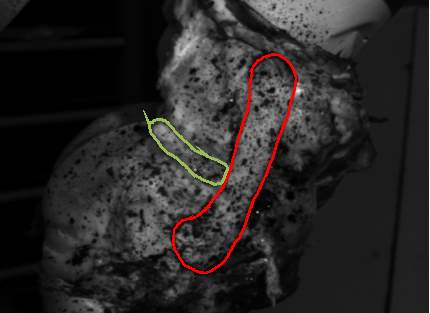
Figure 12. Porcine knee in the robotic testing system showing the exposed MCL and medial meniscus speckled with black ink (MCL outlined in red; medial meniscus outlined in green).
5.1 Aim 1: Strain on the native MCL and medial meniscus
A brief overview of the testing protocol for Group 1 is shown in Figure 13, where strain will be measured on the surface the native MCL complex and medial meniscus with the following ACL states: intact ACL, deficient ACL, and anatomic single-bundle ACL reconstruction.
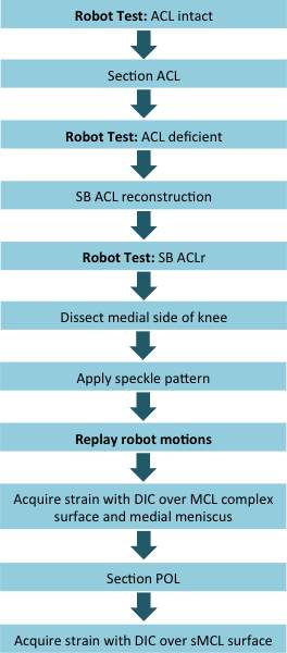
Figure 13. Overview of testing for Group 1, where strain will be measured in the native MCL complex and medial meniscus.
The kinematics obtained by the robotic testing system can be replayed so that strain can be measured using the DIC system. Strain will be measured on the surface of the MCL complex (which is comprised of the sMCL and POL) and the anterior aspect of the peripheral surface of the medial meniscus, which are visible after the medial side of the knee is dissected, as shown in Figure 14. During dissection, all tissue on the medial side of the knee will be removed leaving the native MCL and medial meniscus untouched [59].
After strain has been collected over the entire surface of the MCL complex, the sMCL and POL will be separated by identifying the proximal and distal insertion sites according to the quantitative anatomic description by LaPrade [52]. The POL will be removed, and the kinematics replayed so that strain on the surface of the sMCL can be collected. Note that strain in the ACL graft will not be measured.
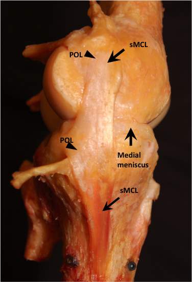
Figure 14. Medial capsule of the knee dissected.
5.2 AIM 2: Strain on the grafts of the MCL reconstruction
For the MCL reconstructions, two different reconstructions will be performed: single-bundle and double-bundle. Both MCL reconstructions are combined with single-bundle ACL reconstruction. In the single-bundle MCL reconstruction, one graft will be used to reconstruct only the sMCL [63]. In double-bundle MCL reconstruction, two grafts will be used to reconstruct the sMCL and POL [9]. Both the single-bundle and double-bundle MCL reconstructions will be performed in an anatomic fashion, where tunnels will be placed at the insertion sites of the native ligaments. Before MCL reconstruction, an incision will be made to expose the sMCL and POL that will be cut to simulate injury. Previously harvested human cadaver hamstring with a 6 mm width will be used to create the MCL grafts. The MCL grafts will be tensioned at 30° of knee flexion under 40 N force using a tension-meter and fixed an interference screw on the tibia and femur. A brief overview of the testing protocol for Group 2 is shown in Figure 15, where strain will be measured on the surface of the MCL grafts.
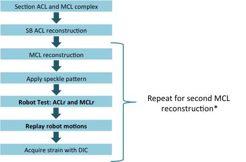
Figure 15. Overview of testing for Group 2 (* the MCL reconstructions will be performed in a randomized order), where strain will be measured in the grafts of the two MCL reconstructions.
The kinematics obtained by the robotic testing system can be replayed so that strain can be measured using the DIC system. Strain will be measured on the surface of the grafts of the two MCL reconstructions, which is visible after the medial side of the knee is opened for reconstruction as shown in Figure 16, showing the double-bundle MCL reconstruction. Note that strain in the ACL graft will not be measured.
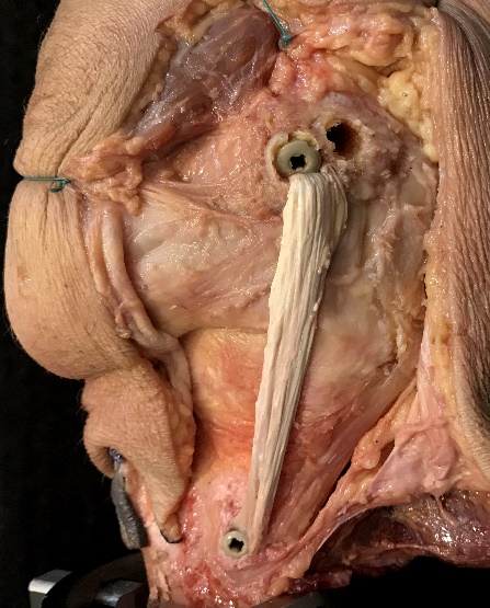
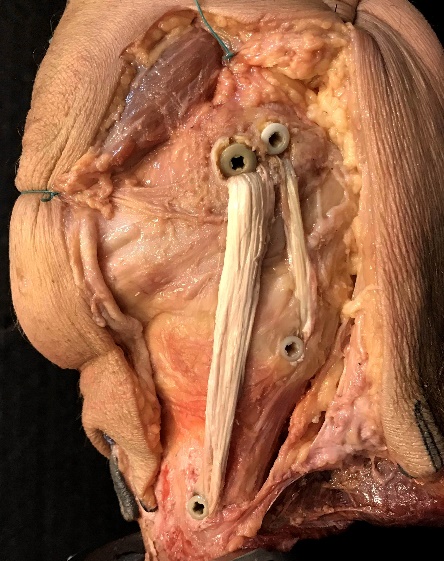
Figure 16. Medial capsule of the knee opened for MCL reconstruction, showing the single-bundle MCL reconstruction (left) and double-bundle MCL reconstruction (right).
5.3 Preliminary results
Preliminary analysis was performed with the robotic testing system on a porcine knee. Briefly, the knee was tested at 30° of knee flexion (full knee extension in the porcine knee) in the robotic testing system at the following loading conditions: (1) 89 N anterior tibial load, (2) 4 Nm internal torque, (3) 4 Nm external torque, and (4) 7 Nm valgus torque. After testing, the knee was dissected of all soft tissue but the MCL and medial meniscus. Black, water-based ink was used to create the speckle pattern, and the robot motions were replayed on the knee for DIC. The results are shown during anterior tibial loading at 30° of knee flexion shown in the MCL (Figure 17A) and the medial meniscus (Figure 17B).
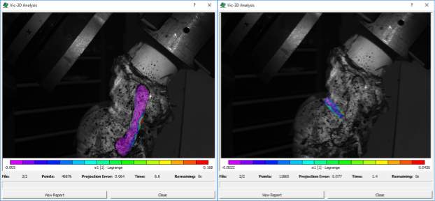
Figure 17. In-situ strain (first principal strain) during anterior tibial translation at 30° of knee flexion A) in the MCL and B) medial meniscus.
The 3-D DIC system will provide strain on the surface of the ligament or meniscus in a Cartesian coordinate system, which is based on the positions of the cameras. The software can also compute the principal strains, and strain in the direction of the longitudinal and transverse axis of the ligament or meniscus. Furthermore, the software allows the user to define a coordinate system by specifying a coordinate transformation. This will allow strain to be reported in an anatomic coordinate system, where anatomical landmarks are used to define axes in the anteroposterior and proximodistal directions of the tibia [26]. To do this, a 3-d digitizer (Faro Arm Platinum; Faro Technologies Inc.) will be used to calculate the transformation from the coordinate system of the DIC system to the anatomic coordinate system. To better analyze local strain between specimens, the MCL will be divided into three regions, as was done by Luyckx et al. [59]. In their study, they divided the MCL into three regions based on anatomical landmarks: proximal, middle, and distal region as shown in Figure 11 above.
5.4 AIM 3: Finite element modeling
Finite element analysis will be performed to model the two different MCL reconstructions (single-bundle and double-bundle). Both MCL reconstructions are combined with ACL reconstruction. Modeling will be performed in a commercially available finite element software package (ANSYS Academic Research; ANSYS, Inc.). In order to perform the finite analysis, the geometry, boundary conditions, and material model of the grafts will need to be specified. A finite element model will be developed for one specimen from Group 2, and a brief overview of the testing protocol is shown in Figure 18.
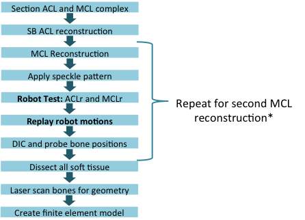
Figure 18. Overview of finite element model development (* the MCL reconstructions will be performed in a randomized order).
3-D models of the tibia and femur will be laser scanned at the end of testing, when all of the soft tissue can be removed. The laser probe will used to digitize the positions of the tunnels of the two MCL reconstructions. The MCL grafts will be modeled as cylinders with a 6 mm diameter with an isotropic hyperelastic material model [76] and a transversely isotropic hyperelastic material model [95]. Material parameters fit to the experimentally obtained stress-strain curves of the human MCL in the literature will be used [29]. The femur and the tibia will be treated as rigid. Note that the ACL graft and the medial meniscus will not be modeled in this study. After finite element modeling is complete, the model will be validated with experimentally measured strain obtained in the same specimen [93].
Two sets of initial loading conditions will be examined: (1) the grafts are in a stress-free state at 30° of knee flexion, and (2) the grafts were assigned an initial stress that corresponds to a total of 40 N tensile load at 30° of knee flexion. The input displacement data for the finite element model will be obtained from the robot testing system. In order to do this, three registration screws (fidicuial markers) will be placed in the tibia and femur so that the positions of the bones can be probed during knee loading in 0.5 mm increments for displacement, and 0.5 degree increments in rotation and knee flexion-extension. The initial loading and boundary conditions will be applied to the finite element model in three steps:
- Step 1: the positions of the femur and the tibial will be fixed. Apply initial graft tension (initial loading condition).
- Step 2: the end surface of the graft on the femoral side will be fixed to the femoral tunnel, and the end surface of the graft on the tibial side will be fixed to the tibial tunnel.
- Step 3: kinematic data obtained by the robotic testing system will be applied to the tibia.
6.0 research plan
The methods described in Chapter 5 of this manuscript will be employed in order to meet the established aims of this study. The timeline for this work is given as follows:
| Task | Spring 2017 | Summer 2017 | Fall 2017 |
| Propose Dissertation. | ✕ | ||
| Aim 1: Strain on the native MCL. | ✕ | ||
| Aim 2: Strain on the grafts of the MCL reconstruction. | ✕ | ||
| Aim 3: Finite element modeling. | ✕ | ||
| Prepare manuscript. | ✕ | ||
| Defend dissertation. | ✕ |
Cite This Work
To export a reference to this article please select a referencing stye below:
Related Services
View allRelated Content
All TagsContent relating to: "Physiology"
Physiology is related to biology, and is the study of living organisms and how they function. Physiology covers all living organisms, exploring how the body performs basic functions in relation to physics and chemistry.
Related Articles
DMCA / Removal Request
If you are the original writer of this dissertation and no longer wish to have your work published on the UKDiss.com website then please:


