Supply and Distribution of Building Services
Info: 10815 words (43 pages) Dissertation
Published: 3rd Dec 2021
Tagged: ConstructionSupply Chain
Summary
This report focuses on the supply and distribution of a range of building services and how they are accommodated within a building. The distribution arrangements for primary services in a building will be assessed. In addition, this work will elaborate on the elements of the superstructure to facilitate the primary services, including cold and hot water supplies. Finally, this report will appraise how the distribution of the primary services impact on the overall design of a building.
Contents
Task 1
Classification of building services
Mechanical Systems
Electrical Supply
Building Operation Systems
Task 2
Water Supply System
Electrical Supply System
Difference between building services and road services
Task 3
Floors
Walls
Ceilings
Legislation and regulations on supply services
Common arrangements for the supply of building services
Task 4
Suspension elements
Choice of floor type
Fire Protection
Fixing services to a building
Bibliography
Task 1: Describe the supply arrangements for primary services in a building structure
This task will describe the supply arrangements for primary services in a building structure. Building services can be described as systems that are in place within a building to meet the requirements of residents who live and work there, they make the dwelling more efficient, safe, functional and comfortable (Chadderton, 2013; Hall, 2015). Primary services are those that are both basic and vital to the daily running of a building, such as water supply, drainage and plumbing (this includes sustainable urban drainage systems), lighting, security and alarm systems. Other services that may be termed as secondary, since a building is habitable without them, are energy supply systems such as solar power and geothermal sources, information and communication systems and escalators (Greeno, 2014; Greeno and Hall, 2009). Services such as water, electricity and gas supplies are supplied initially from outside the building itself, before distribution throughout the building, using various methods within the structure. In this task, I will focus on describing the supply arrangements for primary services within a building structure.
By simple definition, a structure consists of a roof and walls. It is permanently stationary. The principal function of a building is the provision of shelter to its dwellers and occupants, though its prime function should not be limited to occupancy alone. “Building services” enhance the dwelling experience, making the building work. A building must provide an environment within which people feel comfortable, are able to work, live and thrive. All services within a building, making it safe and comfortable, are deemed as ‘Building Services’ (Figure 1).
A building must concur to its designed purpose; not only providing shelter but in addition offering a safe, comforting environment. Building services add to both the up-keep, longevity and functionality of the premises.
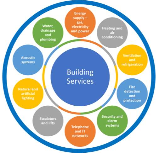
Figure 1 Building Services in summary (Mompó, S. 2017)
Building Services involve
- Energy: electricity and gas
- Water: supply, drainage and adequate plumbing
- Heating, ventilation
- Lighting: both daytime and nightime
- Escalators and elevators where necessary
- Taking advantage of solar, wind and geothermal energy where possible
- Communication: telephone, TV, cable
- Security and private/home alarm systems
- Fire detectors and safety systems
- Air conditioning, refrigeration and ventilation
Classification of building services
Building services are generally divided into the following classifications:
- Mechanical Systems: HVAC systems, drainage, gas input, plumbing and fire precautionary measures.
- Electrical Supply
- Building Operation Systems
These elements are all vital in planning, designing and constructing a building.
Mechanical Systems
HVAC Systems: “heating, ventilation and air-conditioning”.
This includes mechanical and electrical systems, providing self-monitored temperature in buildings.
Environmental thermal control is a major objective for virtually all newly built buildings. Improved thermal comfort will enhance health, satisfaction and overall dwelling experience.
Site Drainage: water control, sanitary disposal, evacuation of waste water
from domestic appliances, soil waste (toilet waste), storm water management, excess water management and surface runoff to the sewers.
Gas supply: This may include commercial gas and a guaranteed supply of oxygen and nitrogen to local amenities, storage, piping, adhering to pressure regulations and the supply of gas from the main source to the desired area. Gas supply is essential to residential buildings where inbuilt. The typical supply of gas to residential homes is via individual gas storage with varying capacities, up to 20kg (Hall, 2015). For residential buildings, such as apartments or high-rise flats, the gas supply stems from a piping system connected to the main tank within the basement of the building. In the US, gas is supplied to households via a network of pipes as compressed natural gas.
The gas supply system is commonly delivered in two alternative systems, the closed ring and the loop system (Greeno and Hall, 2009). These systems guarantee measures that the gas supplies will not be affected if any section of the gas pipeline is disrupted. Supply pipes are buried deep underground, protected from floods and soil erosion through electrical protection methods (protective liner methods, cathode, and grounding) and anticorrosive insulation (Chadderton, 2013).
Plumbing: Water services, sanitation facilities, water storage, distribution through piping and taps ( WC’s, showers etc.) A water supply system can be defined as a network of engineered hydraulic and hydrologic components that guarantee water at the necessary and expected quality, quantity and pressure (Wise and Swaffield, 2012). The main elements of a water supply system include: a drainage basin, a raw water collection base, either above or underground, water purification, pumping stations and access to sewerage facilities, as well as mass water storage such as reservoirs, water tanks and towers. Water is directed via pumping stations and filtered into the water supply network. The source of water is usually via a water treatment and sanitization plant (Moss, 2003; Wise and Swaffield, 2012).
During construction of a building, a water distribution system is inbuilt. The property can then be connected to the mains system through a service pipe. The water from the mains is then distributed throughout the building via the distribution network (Hall, 2015). The water will enter the building via a network of inlet pipes distributed from the main source covering the local vicinity
Fire safety: water supply, sprinklers, fire and smoke alarms, where necessary.
Electricity Supply
The electrical supply of most buildings is gained from the national supply grid. The electricity is then distributed throughout the building using a wiring system or an electrical distribution system (Rigby, 2005). Electric power supply systems consist of units that create high voltage transmission lines to convey electricity across large distances and provide service to buildings. This system of distribution also involves sub-stations that connect all components of a district and service the needs of all the constituents(Chow, 2009). Once a building has been completed, the owner connects the building to the national grid via a service line. The provider meters the electricity in varying forms, feeding into the premises for billing purposes. All buildings share a common electricity supply, gained from the national grid but subsequently sub-sectioned into localised supply outlets.
- Electrical Systems
- Electrical power: Normal, standby, emergency, distribution, interior/exterior and emergency lighting
- Auxiliary: Telephone, data access, audio and cable
- Building operation systems: Elevators, escalators, mobile walkways and parking
- Processing: Food services
- Automation: Environmental control and lighting
- Electrical and Allied Installations in Building
Domestic and electrical installations:
The majority of buildings receive a single-phase supply of electricity from the electricity board, provided at a rate of 240 volts with a frequency of 50 hertz.
The electricity boards cable, from which the domestic supply is sourced, consists of four lines, three carrying a 240-volt supply and the fourth functioning as a neutral line. The neutral line is earthed via the transformer or substation as a safety precaution in the event of a fault with the electrical appliance. Each line is tapped in sequentially along with the neutral, to provide a single-phase 240 V supply.
Electricity board intake (Figure 2)
The supply/intake cable enters the building via either: I. Underground duct or II. Overhead supply. An underground supply is more practical since electrical intake is hidden.
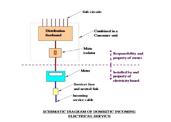
Figure 2: Domestic Electrical Intake (Institution of Electrical Engineers guide (BS 7671))
The consumer unit should be placed close to the point of service entry, the service is then divided into a number of sub-circuits. It is common practice in domestic installations to partition power and lighting circuits so that in the event of a fault, only isolated services are affected.
Commonly, an external cabinet is used for easy access to meter readings. This is situated on an outer wall as illustrated below. Figure 3
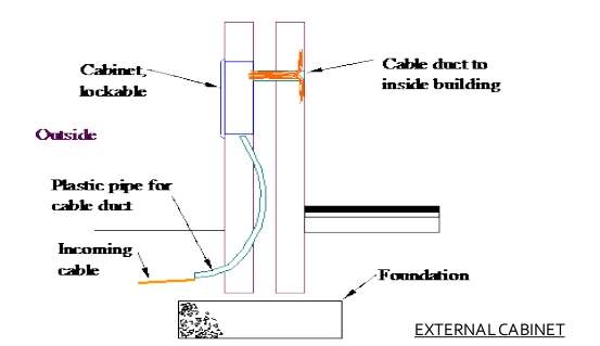
Figure 3: External Cabinet (Institution of Electrical Engineers guide (BS 7671))
Power Circuits:
When planning the number of circuits for a building, a common rule is based on one power circuit per 1000m2 floor area. In larger houses, this may result in dual circuits for power socket placement. In a two storey house, this would cater for both upstairs and downstairs. In larger houses, a separate power supply is also installed for off premises buildings such as detached garages
In all domestic installations, the cooker has a distinct power circuit since electrical use and demand is likely to be high. The immersion heater, since its 3kW load is high, can also be supplied from a separate circuit.
Ring circuits are frequently installed as a safer and more economic method for distributing electricity to sockets. (Figure 4).
The majority of consumer unit manufacturers produce either 8 or 12-way units.
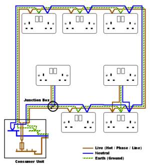
Figure 4: Ring circuits (Institution of Electrical Engineers guide (BS 7671))
Building Operation Systems
Building services are vital for all buildings. Certain commercial outlets, such as department stores or industrial centres, are totally reliant on ventilation, lighting and air conditioning. High rise dwellings rely on lifts and high-speed pressure water supply.
Implementing such services requires a considerable amount of floor and ceiling space, so intricate placement is vital. The role of the designer/architect is paramount in placement of mechanical and electrical input into a building, due to public health, safety, comfort and environmentally friendly issues in new building projects.
The building should be designed to provide optimum lighting, comfortable space, temperature and air distribution and adequate power use. Standards of high-quality sanitation and reliable systems for the protection of life and property must also be met.
To ensure optimum safety and maintenance procedure, NJUG has produced guidelines as to the positioning and colour coded labelling of service supplies. Tables 1 and 2.
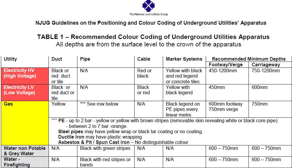
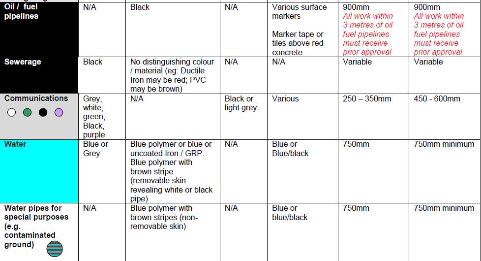
Table 1: Recommendations for positioning and colour coding for building services. NJUG Guidelines on the Positioning and Colour Coding of Underground Utilities Apparatus Issue 8: 29th October 2013 (NJUG, 2013)
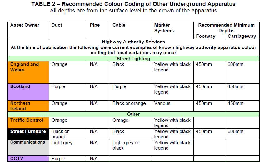

Table 2: Recommendations for positioning and colour coding for other building services NJUG Guidelines on the Positioning and Colour Coding of Underground Utilities Apparatus Issue 8: 29th October 2013 (NJUG, 2013)
Task 2: Explain the distribution arrangements for primary services in a building
(You may want to highlight a typical case study through your own background research. This may also give you an opportunity to highlight the differences between building services and other types of services for projects such as road services, but this should be a comparison and not make up the bulk of your explanation.)
When constructing a building, an engineer must pay attention and give priority to the following services. Electricity distribution, water distribution, gas supply, hot water distribution and heating, ventilation, and air conditioning systems. Electricity, water, gas, and telecommunication systems are the most common and basic service systems. In this paper, I am going to explain the distribution arrangements for the primary services in buildings, which are water distribution systems, electricity distribution systems, and air conditioning systems. I will use the Summit Mall, which is located in Selangor, Malaysia, as a case study to explain the operation of the systems.
Water Supply system
A water distribution system is required to achieve a constant supply of water. The types of systems used for water distribution is contingent mainly on the topography of the region. The three-main means to distribute water are pumped distribution, gravity distribution and combined pumped and gravity systems.
Cold water storage and distribution
Two types of cold water distribution can be used, direct or indirect. For direct systems, water supplied to the building is gained directly from the main supply source, whereas in the indirect system, water is fed into an overhead tank, usually in a loft, and then fed to different floors by gravity.
In the Summit Mall case study, the water is supplied to the mall through gravity and then distributed throughout using a combined distribution system. The water is stored in suction tanks within the basement of the mall. An electrical booster pumps the water to the storage tanks situated on the roof of the building. The water is then distributed throughout the building as shown in Figure 5 below.
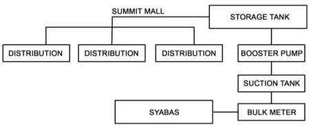
Figure 5 Water Distribution System Diagram of Summit Mall (Jun et al., 2014)
The water supply from the local water treatment plant is transported to the mains via communication pipes. These pipes terminate at the bulk meter, water is then fed into a suction pump located in the cellar or basement. The electrical pump then pumps the water to the top of the building (Jun et al., 2014).
A communication pipe connects the water mains to where the pipe crosses the boundary between the street/pavement and private land (Lonsdale and Obradovic, 1998). Alternatively, a service pipe is fed from the main water supply to the water distribution system of the building in question.
Electrical supply system
Buildings nowadays demand highly on energy, and most of this energy is usually provided as electricity. An elaborate and safe power supply system is used to transport electricity from the source to the buildings where it is distributed to various parts for different applications.
Generated electricity initially passes through a step-up transmission station, its current is increased through a step-up transformer and then transferred via high voltage transmission lines. The electricity is passed through a step-down sub-station prior to distribution to consumers. Generally, there are three main types of consumers: industrial, commercial, and residential, each receiving a different voltage of electricity dependent upon on their needs.
Once in the building, there are many types of electricity distribution methods that can be employed. In my case study, which is the Summit mall in Malaysia, the routine used is as shown in the Figure 6 below.
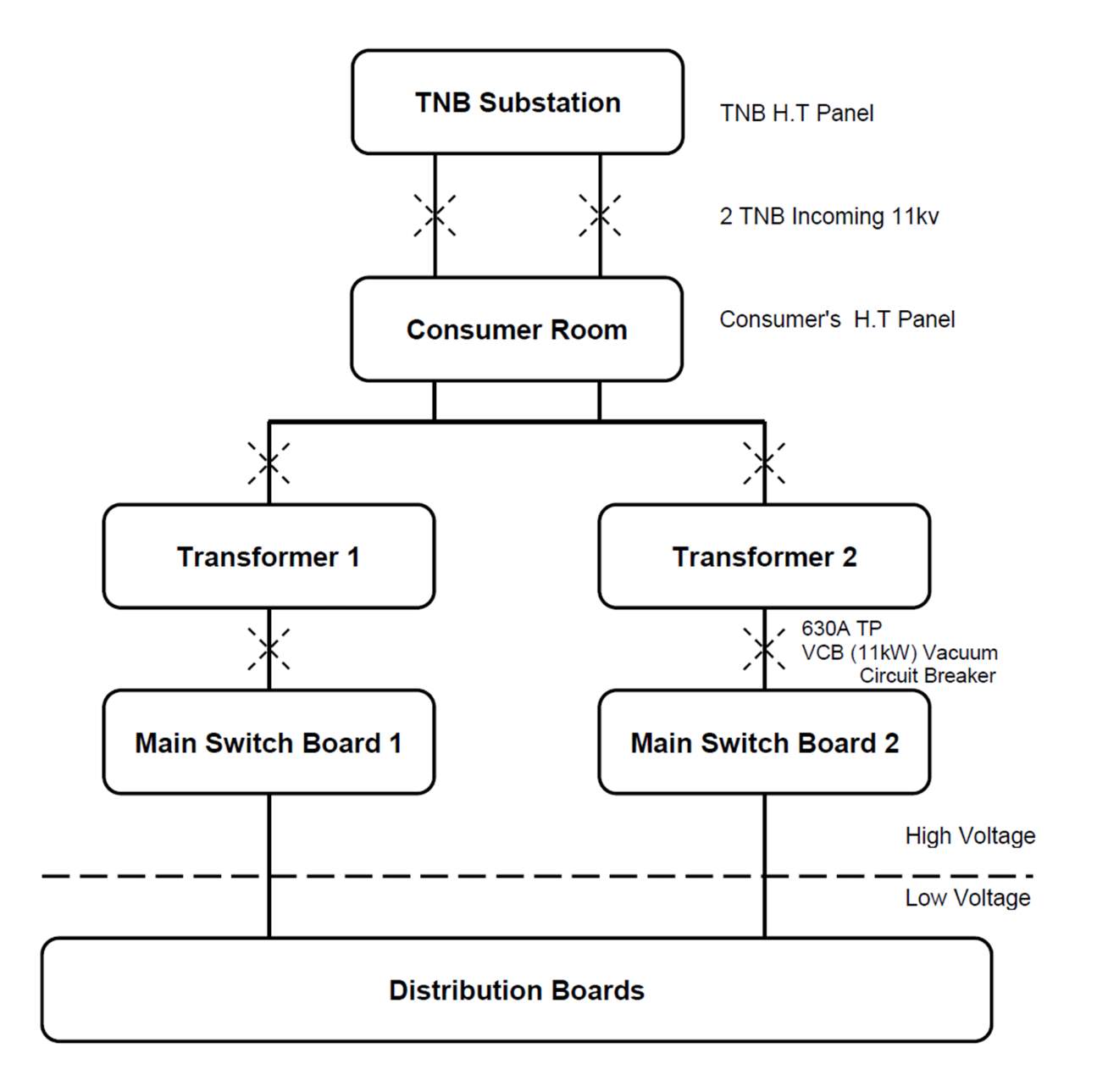
Figure 6 Schematic Diagram of The Main Electrical Routing (Jun et al., 2014)
The TNB substation links directly to the transmission cable supplying electricity. In the summit mall, there are dual mains high voltage incoming power sources from the TNB room into the TNB substation, both are 11kV (Jun et al., 2014). Then they are transferred to the consumer room, which is located next to the TNB room to reduce the amount of voltage drop during transmission.
The consumer room employs step-down transformers to lower the voltage from 11kV to 415v which is adequate for usage (Sivanagaraju, 2008).The 415V current is transferred to the Main Switch Board and distributed to users. There are two types of transformers used in the Summit mall, an oil-insulated transformer and a dry type transformer.
The main switchboards are devices used to monitor the electricity supply from the transformer, always ensuring that the incoming current is 415V +/-1% and the main switch trips when this range is exceeded. From the switchboards, the current goes to the distribution board which is used to control a specific level of specific part of a building’s electricity distribution (Sivanagaraju, 2008).
The mall also features a generator set room which has three basic components, a generator, fuel system, and an exhaust facility. A full tank of diesel can run and supply the whole building with electricity for 24 hours. This room located just beside the transformer room, to minimize the travel distance of the current, reducing voltage drop (Jun et al., 2014).
Difference between building services and road services
Although some services are common to both buildings and roads, there are some minimal differences between the requirements. For instance, roads don’t need air conditioning while buildings need elaborate HVAC systems to maintain a healthy atmosphere in the building. Roads also do not need water supply systems but they a crucial part of any building. Buildings also need some services such as escalators and lifts while road systems rarely need such service installments (Chadderton, 2013; Greeno, 2014).
Services are buried in the road at a nominal depth of 900mm cover and are protected by the various layers of the road make up. Lateral connections transfer the services into consumers’ properties. Figure 7.
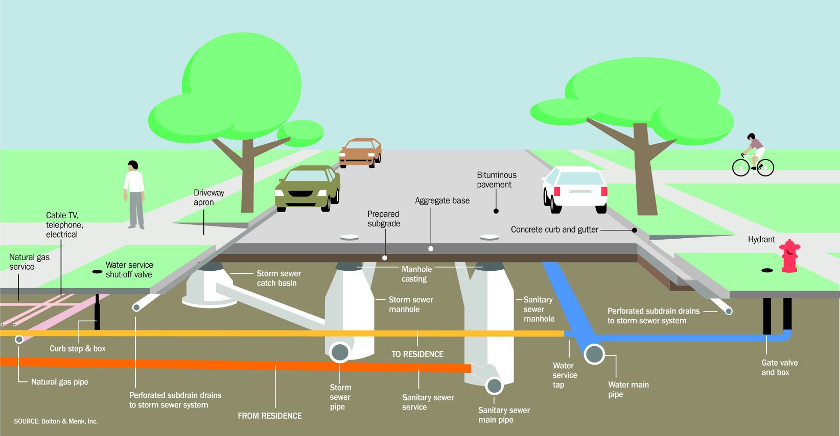
Figure 7 Typical services in road construction (Chadderton, 2013; Greeno, 2014).
Electricity cables are usually placed in ceilings rather than floors because they are more accessible here and are well out of the way of obstacles such as furniture and occupants of the building. They no longer pose as trip hazards and ceilings provide long unobtrusive runs for cables and pipework. This is usually accommodated in suspended ceilings.
Task 3: You are working for a services team for a large main contractor and have been tasked to demonstrate the elements of the superstructure, used to facilitate the primary services.
(You should consider common legislation and regulations surrounding the supply services as well as show common arrangements for the supply of the services. Consider cold, hot water supply and gas supply such as gas-fired boilers, flues to gas-burning appliances, etc.)
The superstructure is the section of a building or structure that is above ground level. It is usually supported by the substructure. The superstructure is where most activity takes place, for example in a building such as a house (Hall, 2015). Because of this, building services commonly innervate the superstructure to facilitate the functionality of the building and to enhance the comfort of the inhabitants. Services provided within buildings include drainage, lighting and water supply (Chadderton, 2013). Further services involve electricity, sanitation, ventilation, acoustics, air conditioning, heating, and fire detection and control. In this task, the elements of a superstructure that facilitate primary services in consideration of common legislation and regulations surrounding supply services will be explored. This study will also feature common arrangements for supply services, specifically cold and hot water supply and gas supply.
Floors
Floor structures are a vital feature in the facilitation of building services, as many service systems can be integrated into or hidden under floors. Floor structures comprise of slabs and beams (Emmitt and Gorse, 2010). The beams are connected to columns that are positioned in key locations for optimum usage of the building. Building services can be integrated within the structural region of the floor, or suspended just beneath it. Structural floors may have a directly installed floor finish, or screed, or even a raised floor to enable space for distribution of either electrical or communication services or both. The premium types of floor, to achieve maximum integration of services into the floor structure, are composite floors. They consist of profiled steel decking, usually lifted onto the steelwork in bundles and then manually placed into position. A fall arrest system is then immediately installed following the steelwork process and prior to the decking being placed. The decking is often placed soon after the steelwork is raised (Best and De Valence, 2002).
Large buildings and commercial buildings, require the provision of mechanical ventilation and air conditioning. The provision of such systems is of vital significance since it affects the placement of structural members throughout the building (Greeno and Hall, 2009). The decision to integrate the services in the basement or to suspend beneath the floor often affects the overall design of the structure, the fire alarm system, cladding plans and the overall height of the building. Some under-floor service systems provide conditioned air via a raised floor (Emmitt and Gorse, 2013). Service integration is attained by passing the air through penetrations in the steel beams. These may be in the form of individual openings in rolled steel beams, or multiple regular or irregular outlets in fabricated beams
Cellular beams provide regular openings (circular) in the web, generated by welding together two parts of a rolled steel section. The top and bottom sections may be cut into beams of varying size and might even be formed from differing steel grades (hybrid sections) (Riley and Cotgrave, 2014). This creates the provision of both an efficient solution for service integration and an increased bending resistance and stiffness. Elongated openings can also be utilised. Integrated floors are usually of a minimum depth and provide for good flexibility in the distribution of building services.
Overall, building service installations in a floor may be designed and installed as laying of trunking by use of a raised floor, installations of raised floors with fire break systems, electrical services that run inside the floor slabs and electric trunking and air ducts running through the raised floor and circulating around the fore-walls in buildings where vibrations are more perceptible (Chadderton, 2013; Greeno and Hall, 2009). Figure 8
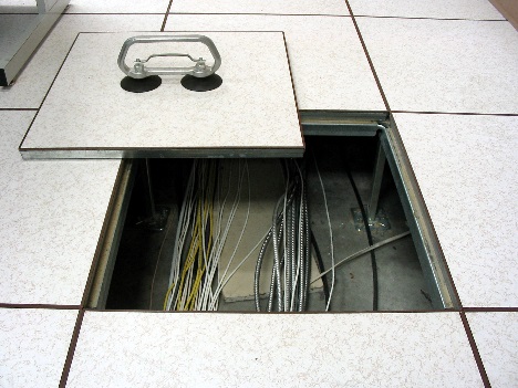
Figure 8 Suspended Floors (British Gypsum, 2015)
Walls
Walls are also a major structural component of the superstructure of a building. They have several crucial functions such as partitioning a structure and acting as a load-bearing element within a structure. Walls also play a vital role in facilitating building services network installation. Service distribution networks are usually conveniently integrated within walls, the electricity distribution system is a clear example. (Riley and Cotgrave, 2014). In the majority of modern buildings, most of the wiring system runs behind or inside the walls and sometimes throughout the floor. This is important as it helps to enhance the aesthetics of a building and protects occupants from potential hazards through placing cables and wires into the wall itself, where no one can accidentally mishandle them. Installing wires within walls also plays the role of protecting the wiring system itself from potential danger such as fire and flooding. Alternative types of wiring systems installed in walls include communication lines and cable television lines (Rigby, 2005).
Other services that are usually integrated into walls are plumbing and drainage systems. Most regular sized water distribution pipes can be conveniently placed into or onto walls. Constant water supply is required for convenient and safe dwelling within a building. HVAC systems can also be fitted onto walls as they innervate the house (Hall, 2015). They form part of the fundamental building services for modern living and are also of significant concern for the fire service. Figure 9
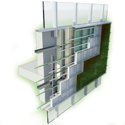
Figure 9 Walls Figure 8 Suspended Floors (British Gypsum, 2015)
Ceilings
Important service systems are installed on the ceiling of a building. A common example is the lighting system. In most buildings, lighting elements are fixed onto ceilings as they can illuminate a large area from this position. Aeration systems such as fans are also commonly fitted onto the ceiling, as they achieve their maximum capability when functioning from above (Emmitt and Gorse, 2013). Figure 10
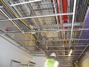
Figure 10 Suspended Ceiling Figure 8 Suspended Floors (British Gypsum, 2015)
Legislation and regulations on supply services
The British Government has published a domestic and non-domestic building services guide, which offers advice and strict regulations for the installation of fixed building services in new buildings, in the attempt to attain compliance with existing energy efficiency obligations of modern building regulations (Hall, 2015). This provision is to ensure both safety and conservation of power and fuel and safety in buildings as the main aim of the government in enforcing these laws.
The recent Grenfell tragedy in London highlights the dire consequences of failure to adhere to a common level of quality standards and compliance in supply services. Though the building was old, lessons have been learned involving the installation and maintenance of supply services for new buildings, and even if the true cause of this tragic event are as yet unclear, the demand for safety and a communal cause regarding the design and structural features of future buildings are clearly defined.
Regarding safety and conservation, laws and guidelines concern the installation of:
- Gas, oil and biomass-fired boilers
- Comfort cooling
- Lighting
- Gas and oil-fired warm air heaters
- Direct electric space heating
- Air distribution
- Domestic hot water
- Heat pumps
- Oil and gas-fired air heaters
- Pipework and ductwork insulation
A common high level of standard and quality control is vital throughout the building industry. The list above includes vital amenities within a building and legislation and regulations are designed to ensure that instalment and maintenance standards are adhered to in all areas. These strict guidelines are not only to avoid the dangers of malfunction within the building, but also to protect the inhabitants from the dangers of the incoming power supply such as gas or electricity. The regulations are also implemented and monitored to conserve power and fully support measures to protect the environment.
Common arrangements for the supply of building services
Coldwater supply system: Direct and Indirect
Direct supply system where the distributed water through the system is gained directly from the mains using a service pipe. Direct from cold water supply Figure 11 or with combination boiler Figure 12
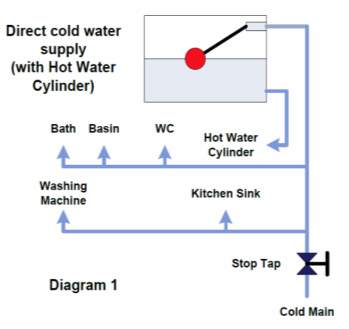
Figure 11 Direct cold water supply system (with hot water cylinder) (APHC, 2017a)
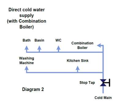
Figure 12 Direct cold water supply system (with combination boiler) (APHC, 2017a)
Indirect supply system
Where the water supplied from the mains is pumped into a storage tank high above the ground, then the water is fed to the distribution system by use of gravitational force (Figure 13)
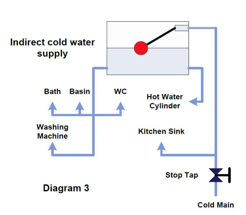
Figure 13 Indirect cold water supply system APHC, 2017a. Understanding cold water systems in the home.
Hot water supply system
Currently, three principal types of the provision of hot water systems are employed: (1) open vented (2) unvented and (3) instantaneous hot water systems (Figure 14)
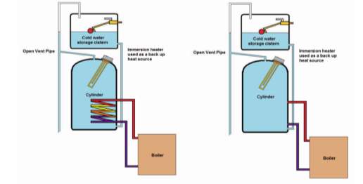
Figure 14 General layout of open vented hot water systems APHC, 2017b. Understanding hot water systems in the home
This type of hot water system utilizes several different components to generate hot water. It comprises a hot water cylinder, a cold-water storage cistern or tank, an open vent pipe and a power source to heat the water. Direct and indirect heating represent the two types of open vented hot water systems:
- Direct heating – in this case the water is heated directly from the heat source using a boiler or via an immersion heater.
- Indirect heating – in this type of hot water system, the central heating and the hot water are detached. The water is heated using a heat exchanger (coil).
Unvented hot water systems
Unvented hot water systems are considered to be more complex, they tend to have more components but permit mains pressure in close proximity to the hot water supply. These types of systems tend to eliminate the need for storage tanks and work at higher pressures relative to open vented systems. Figure 15
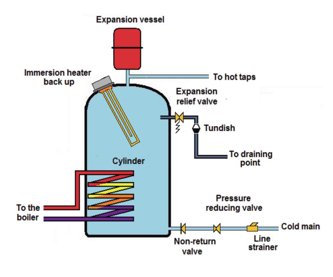
Figure 15 General layout of an unvented hot water system APHC, 2017b. Understanding hot water systems in the home
Instantaneous hot water heating systems
This type of system uses electricity or gas to heat the water to a working temperature but without storing the water itself. Coiled electrical heating elements are used to rapidly heat the water. Figure 16
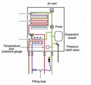
Figure 16 Instantaneous hot water heating system using a boiler APHC, 201 APHC Understanding hot water systems in the home
Given that there are two main means of providing hot water: (1) using a hot water cylinder for storage; and (2) using a combination boiler or multipoint water heater to provide instant hot water, below is an overview of the advantages and disadvantages of both systems. Table 3
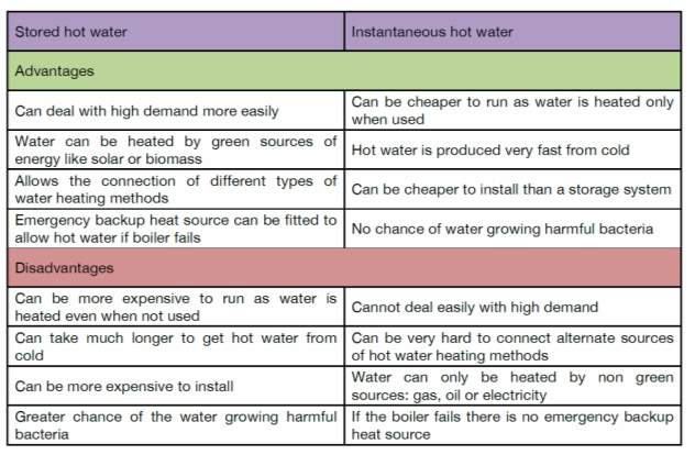
Table 3 Advantages and disadvantages of stored and instantaneous hot water (APHC, 2017b)
Gas supply is generally deemed as highly susceptible to danger due to its explosive potential. Close attention to its planned layout and entrance route to a building is closely monitored.
Gas Supply: Figure 17
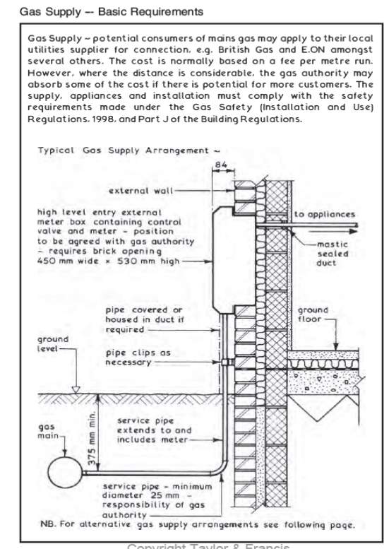
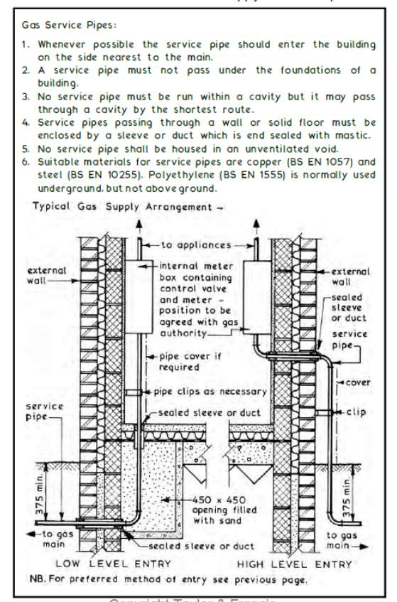
Figure 17 Gas supply to a building (Guyer, 2014)
Gas distribution systems will be planned carefully with due consideration for economy, safety, and uniformity of pressure. The lines will be well-looped within the main area and in all outlying areas whenever practicable and economically feasible to do so. It is not always practicable to loop a supply line to an outlying area and then back into the main system, but in such cases the objectionable effects of dead ends can often be relieved to some extent by looping such line around the area it serves and then back into itself. At large stations it will usually be advantageous to extend the high-pressure line to provide two or more connections with the distributing lines for purposes of uniformity and assurance of adequate pressure. (Guyer, 2014)
Single and 3 phase electric supply Figure 18
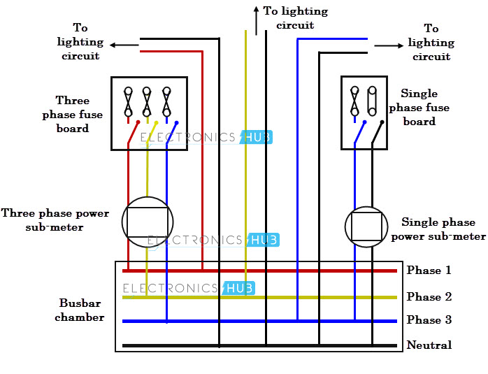
Figure 18 Single and 3 phase electricity supply
Three-phase supplies have properties that make them very desirable in electric power distribution systems:
- The phase currents tend to cancel out one another, summing to zero in the case of a linear balanced load. This makes it possible to reduce the size of the neutral conductor because it carries little or no current. With a balanced load, all the phase conductors carry the same current and so can be the same size.
- Power transfer into a linear balanced load is constant, which helps to reduce generator and motor vibrations.
- Three-phase systems can produce a rotating magnetic field with a specified direction and constant magnitude, which simplifies the design of electric motors.
Most household loads are single-phase. Three-phase power might feed a multiple-unit apartment block, but the household loads are connected only as single phase. In lower-density areas, only a single phase might be used for distribution. Some high-power domestic appliances such as electric stoves and clothes dryers are powered by two or three phases instead of one in order to use lower currents, so households with such appliances must be provided with more than one phase.
Task 4 – Appraise how the distribution of the primary services impact on the overall design of the building
This task will use a range of case studies to appraise how the distribution of the primary services impact on the overall design of the building.
The purpose of primary services is to create a comfortable and safe working environment for people and processes by providing warmth, cooling, lighting, electrical power, water, sanitation, drainage, transport, communication, noise control, security and fire protection. They play a significant part in generating a successful indoor environment. When working properly they tend to be ignored or taken for granted (Armstrong et al.,2005; Burberry, 2014).
The demand for increasing standards of environmental control in buildings and the provision of primary services continues to increase as does the complexity of the techniques and equipment available to distribute the services around the building (Armstrong et al.,2005).
The global need for conservation of resources and control of pollution is a new determinant in the environmental and services design of a building. New buildings are subject to increasingly stringent standards of insulation and a push towards a reduction in energy consumption (Burberry, 2014).
With primary services, the economic layout and careful analysis of loads to be met are critical to the efficiency and economy of installation. Design considerations must include ease of access for adjustment and maintenance and replacement during the lifetime of the building. This influences the overall design of the building as will be discussed below.
A building service engineer designs and installs elements of a building, ensuring it is a home for the dwellers. Most new buildings require a labyrinth of ducts and pipes, together with miles of cabling, to ensure primary services are provided. These requirements need to be supported to safely transfer the responsibility of work and support without causing damage to services nor structure. Structural elements such as steel decking, concrete slabs and beams are regularly used to support mechanical and electrical services in buildings.The method by which these services are supported within the structure depends upon the requirements of each installation, such as the overall load, the positioning of fixing points on the supporting structure and the attachment options for the suspended item. A building service engineer designs and installs elements of a building which bring it to life. From lighting to escalators, security systems to lifts, -they are in control. Building service engineers now influence the orientation and overall design of a building to optimise local conditions and maximize renewable technologies (Beer, 2012).
The variety of locations from which these services can be suspended provide the building service engineers with many options at the design stage, and offer them the flexibility to overcome unforeseen difficulties that may arise during installation. However, fulfilling time and cost saving aims through innovative suspension systems requires pre-determined and close coordination between the building services design team and structural engineers. As is often the case in building design and construction, the success or failure of a project depends as much on the design of the interface as it does on the design of individual beams, columns and building service systems.
The range of building services commonly suspended or supported by building structural elements include:
- Fan coils/air handling units
- Radiant heating/cooling (radiant tubes, panels and chilled beams)
- Cable trays
- Ceiling grids
- Luminaires and lighting
- Ductwork
- Trunking
- Busbars
- Pipework
- Signs and indicator displays
- Decorative objects
Prior to the design stage of a suspension system, the requirements and constraints imposed by the building structure and operational environment need to be fully comprehended by the designer. Once a configuration has been selected, the system designer must calculate the loads on each fixing to ensure that suitably strong components are deduced, specified and checked with the structural engineer, to ensure that design loads have not been exceeded. Designers should check that the weights provided to the structural engineer reflect the actual loads to be experienced during the building operation, such as fan coils filled with water.
Suspension elements
The common suspension element is a rigid component, usually a threaded rod. While this generally in tension, it in addition provides resistance to compressive forces, aiding in ensuring the rigidity of an installation. An alternative to the threaded rod is wire rope-based suspension. Though these elements are durable under tension, they provide little resistance to either compressive or bending loads. Careful design (e.g. placing wires at angles – see below) can offer suitable restraint.
Most threaded rod systems (fixings, threaded rod and related fittings) are over-specified for the majority of applications, allowing greater freedom for installation. Wire rope systems, on the other hand, tend to be specific to the design load and may be overstressed if installation is not correct. Though threaded rods are generally mounted vertically, wire rope systems can be easily installed at any given angle. This significantly enhances the range of suspension points that can be used. However, it has drawbacks: increased load on fixings, which must be considered in the design. Detailed information on the suspended load will be required. For a simple run of services, all that may be needed is the weight per metre and any limits on maximum support spacings.
For complex items, dimensions, weight, centre of gravity, and suspension attachment points may need to be ascertained. Consideration should be given to the types of load that may be applied to the suspension system. Although most loads in building services applications are static, some equipment may emit brief dynamic episodes, especially during start-up. Pipework, for example, can undergo a shock loading when pumps are suddenly opened or stopped. Other constraints include the supporting structure and operating environment of the building. The materials and permissible fixing points should be identified. Any environmental constraints should also be noted, such as a corrosive atmosphere. Swimming pools, for example, can be corrosive atmospheres, and require the use of corrosion-resistant hangers.
Load calculations
Data on the mass of services to be suspended, such as the weight per metre of items such as pipes and ductwork should be obtained from manufacturers and system suppliers. Designers should check that these weights reflect the loads to be experienced during service operation. The weight of pipework and terminal units, such as fan coils, should not be given in dry conditions, but must include the additional contributory factor of water.
Choice of floor type
The use of support systems that fasten to the underside of steel floor decking provide the building services engineer with a degree of choice regarding the location of the services and their supports, without the need for costly site activities such as drilling into the concrete slab. However, this advantage can only be granted if a suitable floor type is chosen. As this is one of the initial decisions taken in the building design process, clients should recognise the importance of including building services engineers in the decision-making process at the earliest possible stage.
Fire protection
In choosing fire protection for the beams, structural designers should consider the need to install services, particularly in cases where a mechanical connection must be imposed upon the beam flange. Board fire protection should only be used where contractors are not likely to support services from the beams. The act of cutting away the board to accommodate clamps would compromise fire protection. With fire retardant blankets or cement-based spray protection systems, a wire rope system can be used to support the service. Again, the direct attachment of clamps to the beam flanges will not be possible. Intumescent coatings are probably the most favourable fire protection solution where flange clamps are used, although care must still be taken to ensure that the fire protection system is not damaged during the installation of the building services.
Fixing services to a building
Contemporary forms of building construction provide building services engineers with many opportunities in supporting the mechanical and electrical services.The choice of attachmentwill depend on a number of factors, including the layout of the structural frame, thetype of floor construction, the size and weight of the services to be supported and their locationwithin the building.
The choice of fixing will depend on a variety of factors: whether the floor slab is of lightweight steel or heavyweight concrete and whether the building is new or being refurbished. Designers will seek to provide the simplest and quickest configuration to install, while meeting the requirements for load stability and easy access, as well as any requirement for redundancy should a subsystem of the suspension system fail.
Designers must comprehend the actual loads of components, and the conditions in which they are expected to operate. They should obtain details of the safe working load and limits declared by the supplier as being the maximum load a component or system is capable of handling. Designers should be aware that components with a fire rating may have their standard safe working load reduced to ensure they provide adequate strength under extreme conditions.
Primary steelwork
Services may be supported directly from the main structural beams, either using clamps attached to the bottom flange or wire rope passed around the section. Several types of clamp are available to suit attachment to parallel flanges and tapered flanges. Where necessary, attachments can be made to inclined flanges using a swivel-flange clamp. Small services, such as cables, may be carried on top of the lower beam flange, held in place by clips. Alternatively, if the building use and finish permit, cables may be carried via cable trays attached directly to the columns.
The advantage of supporting services directly from primary steelwork is that the weight of the service is usually minimal compared to the imposed loads carried by beams and columns. Consequently, the additional loads can be carried without a significant increase in section size. In most cases, the beams and columns will usually be designed for service loads, whether or not the services are carried directly by the steel members. The loads will be taken by the primary steelwork at some point in the load path.
One disadvantage of supporting services directly from the primary steelwork is that the location of support is restricted to points on the structural grid. Where services run perpendicular to the beams supporting them, the resulting span may exceed the maximum unsupported length for the service duct or pipe.
Secondary Steelwork
In some cases, it may be possible to suspend services from secondary steelwork such as purlins or side rails. Where purlins are used, the same options exist as for structural beams (wire rope round the section or clamps attached to the flanges). Special clips are available for attachment to purlin flanges or, where heavy duty support is required, to the purlin web. Cables may be carried in specially-designed cable trays that fit inside the purlin flange. Unlike primary structural steelwork, purlins and side rails are made from light gauge steel and are designed to support relatively small loads. Care must therefore be taken to ensure that they can support the service in addition to the other design loads such as cladding the dead load and the weight of snow.
The advantage of using secondary steelwork is that many more potential attachment points are provided as would be the case with primary steelwork, thereby reducing the span of the services and maximising the options for the building service engineer.
The advantage of suspending the services from the decking is that the re-entrant slots are typically only 100-150 mm apart, providing considerable choice regarding the location of the services. Provided that the safe working load of the floor slab is not exceeded, new services can easily be attached at any time over the operational life of the building.
The need to cut holes into a concrete element, allowing passage of service, is a common requirement.Occasionally, problems are simple to resolve, but others may require design expertise and enhances involvement between structural and service personnel. For vital areas, exposed concrete finishes in occupied areas for example, engineers need to liaise closely with the client, architect and installing contractors concerning the details to ensure a functional and aesthetically acceptable solution.
Services and structural engineers must work together to ensure that decisions placed by the structural engineer suit all requirements. The reverse also matters, as the technical demands of a service solution may influence elements of the overall design. It is in the client’s interest to maintain a close working relationship.
It is common for holes to be placed into reinforced concrete elements, generally to allow for the passage of service. Where possible, the structure should be designed to integrate a service zone to minimise the requirement of holes for service runs. Although this is a common situation confronted by designers, guidance on the design and placement of holes is limited.
Project pre-planning
Pre-planning is obviously preferred to retrospective need of holes or openings. Pre-planned holes are generally marked clearly on the layout drawings. They have been integrated into the configuration to ensure the resultant stresses are distributed evenly and it is not compromised.
The structural perspective
Circular holes are preferable since square or rectangular holes may induce stress around their corners, increasing any risk of cracking. If the hole is formed in an element at the precast factory stage or formed in-situ is irrelevant.
There are three types of pre-planned holes:
- Holes cast on construction of the element and are open, ready to receive service.
- Services that are already cast and remain in position
- Areas within the concrete element, designated for holes to be cut in time.
Occasionally, there may be a requirement for a larger hole to be placed within an element where standard general guidance does not apply. It is impossible to offer definitive guidance in such scenarios since each case will differ. When larger holes are required, an experienced structural engineer needs to be consulted to assess and advise on any resulting capacity of the element and to apply additional strengthening.
There are many factors influencing the design of concrete structures to interface with services such as:
- Light fittings
- Low voltage electrical distribution
- Embedded pipework systems (active thermal storage)
- Risers through floor slabs
- Drainage
- Distribution of pipework and ductwork.
Engineers need to work together closely in the initial building project to ensure that decisions made will suit the service requirements. The opposite is also true, as technical requirements may affect the structural design. It is in the client’s interest that this close working relationship is maintained.
An example of an interface issue is the integrity of fire separation. Holes in the façade or in floor slabs may be required to aid natural ventilation. The structural engineer’s preference for down stand beams and drops at column heads may obstruct service runs, both horizontally and vertically.
Planning for future requirements is also important from a services perspective. In setting a design brief, the client, architect and engineers must consider the building services in terms of timescales regarding replacement. The life span of a concrete building may be upwards of 50 years, but the services may be significantly upgraded or replaced several times in that period. The replacement or additional building services (from extra cabling and ductwork to lifts and escalators) often coincides with a change of use. Clients regularly demand flexibility in their buildings to cope with such eventualities, and therefore the durability of the concrete elements to accommodate new services should be considered during a building’s initial design. For example, it may be cost effective to provide larger cast-in cable-ways for future expansion.
Exposed concrete structures
An increasing number of clients express a preference for exposing the concrete structure internally, regularly for reasons of aesthetics, but often as a way of using the concrete’s thermal capacity to control the building’s internal temperature. Where concrete is exposed in occupied areas, it can be used to moderate space temperatures to the extent that mechanical cooling may not be required. However, this places two key constraints on the services and structural engineers:
- where concrete is visible, it usually needs a higher quality finish.
- Services will need to be fixed, run through, or suspended from the concrete and this will demand a far higher quality of interface engineering than is normally required.
Active thermal storage
Engineers are finding ways to improve the thermal capacity of the concrete structure, and increase its slow response time. Innovations include casting pipework into floor slabs to carry cold water. This can be pumped through the slab to remove excess heat caused by solar gains and heat from office equipment. Active thermal storage systems need pre-project teamwork between all parties, right through to the concrete fabricator and installing contractor.
Fixings and fittings
Where services are to be attached to an exposed concrete surface, such as chilled beams or light fittings, any irregularities will show in poor alignment of the fittings. Even where the services are suspended from the concrete rather than cast within it, the architect, structural engineer and service engineer need to ensure that their interface engineering resolves all these issues. Such solutions not only require client input at the outset of the project, but early involvement of the building contractor and heating engineers with the structural and services designer.
Plantrooms and basements
The hidden areas of a concrete building are just as demanding as the visible areas, particularly when it comes to penetrating the fabric to run drainage or electrical services. Efficient water proofing is essential. Details such as puddle flanges need to be correctly recorded and properly installed to guard against water ingress.
Several case studies illustrate the distribution of building services to the design of buildings.
The new Hepworth Gallery provides optimum illumination, designed by Arup lighting, created by Hepworth Wakefield, one of the largest purpose-built galleries in the world (Lam 2011). The approach taken in this project had two main goals: to conserve the gallery’s temporary exhibition sites and to present Barbara Hepworth’s original sculptures in an optimum light. Arup developed a method to assess how a certain geometry/fenestration responded to daylight. If the exposure exceeded the allowable limits, shading systems were used to optimize the lighting scenarios. The designed windows within the galleries create visual connections for visitors to the river and the surrounding landscape and at the same time allowed visitors to gain a glimpse of inside activity.
Another case study is the design and construction of a visitor center with an A-rated EPC. The Centre was Brockholes Nature Reserve Visitor Centre. The project was posed great challenges for the designers. It required the design of a visitors hop centre, complete with a shop, exhibition space, classroom, and conference centre in the middle of an ecologically sensitive site in the middle of a floodplain. The aim designer was Hareth Pochee, from the Max Fordham firm, who teamed up with Adam Khan Architects, quantity surveyor Jackson Coles and structural engineers Myers and Price to create the design for a Visitor Centre for Brockholes Reserve, located close to the River Ribble near Preston.
In this project, the major priority of the client was utility performance and environmental performance. One result of their studies was that concrete, rather than steel, was used to construct the floating pontoon. The walls and roofs are formed from a structural insulated panel, topped by an oak shake roof, a perfect combination of energy efficiency materials. The choice of concrete over steel would have been very unconventional in any other situation.
The design of the Greenwich Intercontinental Hotel next to London’s O2 was greatly influenced by the services and utility requirements by the client. The hotel was designed to achieve the Breeam Very Good standards, and the residential units gained a clean level 4 Code for Sustainable Homes. To meet these green targets, the project team placed low-energy heating, and air conditioning, and then created a provision in the design for the connection to the Greenwich Peninsula heating system. This had a significant effect on the overall design of the building.
Bibliography
APHC, 2017a. Understanding cold water systems in the home.
APHC, 2017b. Understanding hot water systems in the home.
Armstrong, J., Saville, A., Race, G. L., Butcher, K., Engineers, C. I. of B. S., & Staff, C. I. of B. S. E. (2005). Managing Your Building Services. Chartered Institution of Building Services Engineers (CIBSE).
Beer, R. (2012). So, What Does a Building Services Engineer do, exactly? Retrieved from https://www.theguardian.com/careers/building-services-engineer
Best, R., De Valence, G., 2002. Design and Construction: Building in value. Routledge.
Building Services Engineer. (2017) Retrieved from Building services. (2017), Retrieved from https://www.designingbuildings.co.uk/wiki/Building_services
Burberry, P. (2014). Environment and Services. Taylor & Francis.
Chadderton, D. V, 2013. Building services engineering. Routledge.
Figure 8 Suspended Floors (British Gypsum Ltd, (2015), The White Book, 10th Ed.London, British Gypsum)
Chow, T.T., 2009. Development trends in building services engineering. City University of HK Press.
Emmitt, S., Gorse, C., 2010. Barry’s advanced construction of buildings. John Wiley & Sons.
Emmitt, S., Gorse, C.A., 2013. Barry’s introduction to construction of buildings. John Wiley & Sons.
Greeno, R., 2014. Building Services, Technology and Design. Routledge.
Greeno, R. & Hall, F. (2007). Building Services Handbook: Incorporating Current Building & construction regulations. United Kingdom: Elsevier Ltd.
Greeno, R., Hall, F., 2009. Building Services Handbook. Routledge.
Greenwich Hotel Opens Door to District Heating (2017). Retrieved from https://www.cibsejournal.com/case-studies/
Guyer, J.P, (2014). An introduction to gas distribution. CreateSpace Independent Publishing Platform.
Hall, F., 2015. Building services and equipment. Routledge.
Imwenhao. (2014). The Installation of hot water supply systems. Retrieved on November 29, 2017 from https://www.slideshare.net/imwenhao/the- installation-of-hot-water-supply-for-hotel
Institution of Electrical Engineers (IEE) guide (BS 7671)
Jun, Y., Lin, Y., Wei, K., Chyin, C., Cheng, T., Ngoh, H., Hao, E., 2014. Case Study and Documentation of Building Services Systems, Summit Mall.
K.P Lam, 2011, Building energy and comfort management through occupant behaviour pattern detection based on a large-scale environmental sensor network
Lam, F. (2011). CIBSE Case Study. CIBSE Journal. Retrieved from https://www.cibsejournal.com/
Lee, G(2014) Building Services. Retrieved from
https://www.slideshare.net/gertrudeleeys/building-services-project-1
Lonsdale, P. & Obradovic, D. (1998). Public Water Supply: Models, Data and Operational Management
Moss, K., 2003. Heating and Water Services Design in Buildings. Routledge.
NJUG, 2013 Guidelines on the Positioning and Colour Coding of Underground Utilities Apparatus Issue 8: 29th October 2013
None Domestic Building Services compliance guide.(2017). Retrieved on November 29, 2017 fromhttps://www.designingbuildings.co.uk/wiki/Non-a domestic_building_services_compliance_guide
Pearson, A. (2012). Visitor Centre with a-Rated EPC. Retrieved from https://www.cibse.org/knowledge/knowledgeitems/detail?id=a0q20000008JgXZ
Rigby, B., 2005. Design of electrical services for buildings. Taylor & Francis.
Riley, M., Cotgrave, A., 2014. Construction technology 2: industrial and commercial building. Palgrave Macmillan.
Sivanagaraju, S., 2008. Electric power transmission and distribution. Pearson Education India.
Wise, A.F.E., Swaffield, J., 2012. Water, sanitary and waste services for buildings. Routledge.
Zhang, Stephen X, Babovic, Vladan (2012). “A real options approach to the design and architecture of water supply systems using innovative water technologies under uncertainty”. Journal of Hydroinformatics. 14 (1): 13–29.
Cite This Work
To export a reference to this article please select a referencing stye below:
Related Services
View allRelated Content
All TagsContent relating to: "Supply Chain"
A Supply Chain is a system in place between companies and their suppliers, from producing a product to distributing it ready to be sold. An effective and smooth running supply chain can contribute to the successful running of a business.
Related Articles
DMCA / Removal Request
If you are the original writer of this dissertation and no longer wish to have your work published on the UKDiss.com website then please:


