Computer Numerical Control (CNC)
Info: 10282 words (41 pages) Dissertation
Published: 25th Nov 2021
Tagged: Computing
Contents
Click to expand Table of Contents
Chapter 1 - INTRODUCTION
1.1 Introduction
1.2 Computer Numerical Control (CNC)
1.3 2D CNC Plotter
1.4 Point of the Thesis
1.5 Literature Review
1.6 Motivation
Chapter 2 - PROJECT DESCRIPTION
2.1 Introduction
2.2 Hardware
2.3 Software Programming
2.4 Industrial Design
Chapter 3 - HARDWARE
3.1 Introduction
3.2 ARDUINO UNO Board
3.3 L293D
3.4 Servo Motor
3.4.1 Working standard of Servo Motor.
3.4.2 Controlling Servo Motor
3.5 Stepper Motor
Chapter 4 - SOFTWARE
4.1 Introduction
4.2 Inkscape.Ink
4.2.1 Scalar Vector Graphics (SVG)
4.2.2 Inkscape Window
4.2.3 Inkscape Program
4.2.4 Generating Gcode records utilizing inkscape
4.3 CAMotics
4.4 Arduino IDE
4.5 Processing 3.2.4
4.5.1 Sketching with Processing
Chapter 5 - INDUSTRIAL DESIGN
5.1 Introduction
5.2 X Axis and Y-Axis
5.3 Aluminium Stand holder
5.4 Pen Setup (Z-axis)
5.5 Final Setup
Chapter 6 - PROJECT IMPLEMENTATION
6.1 Introduction
6.2 Steps Involved in the Project
6.3 Result
Applications
Conclusion
References
Bibliography
Table of figures
Figure 1: The 3-dimensional coordinate planes
Figure 2:: Intersecting lines form right angles and establish zero point
Figure 3:The quadrants shaped when the X and Y axis cross are utilized to precisely situated over the X hub.
Figure 4: Arduino UNO Board
Figure 5:L293D Motor Driver Circuit
Figure 6: Servo Motor(external view)
Figure 7: Controlling of Servo Motor –shaft motion (PWM)
Figure 8: Stepper Motor(from CD drive)
Figure 9: Inkscape Window
Figure 10: Processing 3.2.4 Window
Figure 11:CD Drive with Stepper Motor
Figure 12: Aluminium stand
Figure 13: Pen setup
Figure 14: side view
Figure 15: Major Block Diagram
Figure 16: Plotted Output Images
Chapter 1 - INTRODUCTION
1.1 Introduction
CNC remains for Computer Numeric Control and normally alludes to a machine whose operation is controlled by a PC. The most widely recognized utilization of CNC, and the one important to us, is the name given to gadgets that, under PC control can cut, scratch, process, etch, construct, turn and generally perform fabricating operations on different materials. Regularly, a CNC machine can move a cutting or 3D printing head in 2 to 6 tomahawks, implying that it can position that device head at an exact point in or on the material to make the cut or operation coveted by then. By moving the head through various focuses, the cutting head can cut or shape the plan spoke to by an information stream of situating focuses being sent by the PC. By controlling a CNC machine through a PC it is workable for the client to outline an item on-screen, change over it to CNC-clear code and afterward send that information to the CNC machine for it to deliver a physical duplicate of the thing planned.
1.2 Computer Numerical Control (CNC)
The term numerical control is a generally acknowledged and normally utilized term in the machine device industry. Numerical control (NC) empowers an administrator to speak with machine devices through a progression of numbers and images.
NC which rapidly progressed toward becoming Computer Numerical Control (CNC) has conveyed huge changes to the metalworking business. New machine apparatuses in CNC have empowered industry to reliably create parts to exactnesses undreamed of just a couple of years prior. A similar part can be recreated to a similar level of precision any number of times if the CNC program has been appropriately arranged and the PC legitimately modified. The working summons which control the machine device are executed naturally with stunning pace, precision, effectiveness, and repeatability. The perpetually expanding utilization of CNC in industry has made a requirement for faculty who are proficient about and fit for setting up the projects which manage the machine apparatuses to create parts to the required shape and precision.
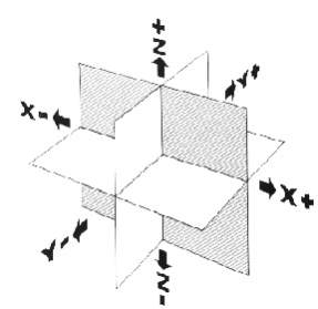
Figure 1: The 3-dimensional coordinate planes
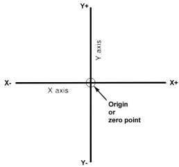
Figure 2:: Intersecting lines form right angles and establish zero point
Cartesian Coordinate System
Nearly everything that can be created on an ordinary machine device can be delivered on a PC numerical control machine apparatus, with its many points of interest. The machine device developments utilized as a part of delivering an item are of two fundamental sorts: indicate point (straight-line developments) and ceaseless way (shaping developments).
The Cartesian, or rectangular, facilitate framework was concocted by the French mathematician and savant Rene’ Descartes. With this framework, a particular point can be depicted in scientific terms from some other point along three opposite tomahawks. This idea fits machine devices superbly since their development is for the most part in view of three tomahawks of movement (X, Y, Z) in addition to a pivot of turn. On a plain vertical processing machine, the X pivot is the level development (right or left) of the table, the Y hub is the table cross development (toward or far from the section), and the Z hub is the vertical development of the knee or the axle. CNC frameworks depend vigorously on the utilization of rectangular directions in light of the fact that the software engineer can find each point on a vocation unequivocally.
The three-dimensional facilitate planes are appeared in Fig. 1.2. The X and Y planes (tomahawks) are level and speak to even machine table movements. The Z plane or pivot speaks to the vertical instrument movement. The in addition to (+) and short (- ) signs demonstrate the heading from the zero point (source) along the pivot of development. The four quadrants framed when the XY tomahawks cross are numbered in a counterclockwise course (Fig. 1.3). All positions situated in quadrant 1 would be certain (X+) and positive (Y+). In the second quadrant, all positions would be negative (X-) and positive (Y+). In the third quadrant, all areas would be negative (X-) and negative (Y-). In the fourth quadrant, all areas would be certain X (X+) and negative (Y-). In Fig. 1.3 , point A future 2 units to one side of the Y hub and 2 units
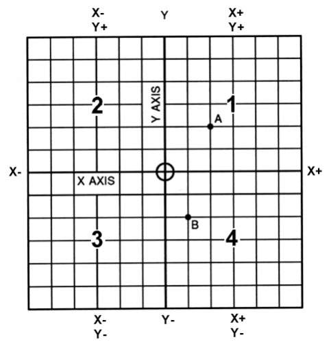
Figure 3:The quadrants shaped when the X and Y axis cross are utilized to precisely situated over the X hub.
Expect that every unit levels with 1.000. The area of point A future X + 2.000 and Y + 2.000. For point B, the area would be X + 1.000 and Y – 2.000. In CNC programming it is not important to show in addition to (+) values since these are expected. Notwithstanding, the short (- ) values must be demonstrated. For instance, the areas of both An and B would be demonstrated as takes after:
A X2.000 Y2.000
B X1.000 Y-2.000
1.3 2D CNC Plotter
The plotter is a computer printer for printing vector graphics. In the past, plotters were used in applications such as computer-aided design, though they have generally been replaced with wide-format conventional printers. A plotter gives a hard copy of the output. It draws pictures on a paper using a pen. Plotters are used to print designs of ships and machines, plans for buildings and so on.2D Plotter is a plotter that offers the fastest way to efficiently creates extensive drawings. Pen plotters will have the capacity to print by moving a pen or other written work gadget over the surface of a bit of paper. This implies plotters are vector design gadgets, as opposed to raster representation. Pen plotters can draw complex line workmanship, including content, yet do as such gradually due to the mechanical development of the written work gadget, for example: pen.
1.4 Point of the Thesis
Point of the proposition is to set up a 2D Plotter for the accompanying requirements:
- A general thought of CNC Models.
- Generating GCODE. Coordinating the distinctive sorts programming alongside the equipment setup.
1.5 Literature Review
1. Jae Wook Jeon and Young Youl Ha, A Generalized Approach for the Acceleration and Deceleration of Industrial Robots and CNC Machine Tools, IEEE Transactions on Industrial Electronics, Vol. 47, No. 1, February 2000, pp. 133-139.
Numerous systems for the speeding up and deceleration of mechanical robots and PC numerical control (CNC) machine instruments have been proposed to make modern robots and CNC machine apparatuses perform given errands effectively. Despite the fact that the methods choosing polynomial capacities can create different increasing speed and deceleration attributes, the significant issue is the computational load. The advanced convolution methods are more productive than the strategies choosing polynomial capacities. In any case, neither one of the velocity profiles of which the deceleration attributes is free from the speeding up qualities nor those of which the quickening interim is unique in relation to the deceleration interim can be produced by the advanced convolution methods. This paper proposes a summed up approach for creating speed profiles that can’t be produced by the computerized convolution strategies.
As indicated by the coveted qualities of increasing speed and deceleration, each arrangement of coefficients is computed and is put away. Given a moving separation, and quickening and deceleration interims, a speed profile having the coveted attributes of increasing speed and deceleration can be proficiently produced by utilizing these coefficients. A few speed profiles created by the proposed procedure will be connected to one single-hub control framework.
2. Allen G. Morinec, Power Quality Considerations for CNC Machines: Grounding, IEEE Transactions on Industrial Electronics, Vol. 38, No. 1, January/February 2002, pp. 3-11.
PC numerical control (CNC) machines are utilized to shape metal parts by processing, drilling, cutting, boring, and crushing. A CNC machine by and large comprises of a PC controlled servo-speaker, servo-engines, shaft engine, and different tooling. The machine can be modified to shape a section by utilization of a front control board. More refined models permit a PC supported outline attracting to be transferred to the machine. The electronic segments inside a CNC machine are especially delicate to the establishing systems utilized as a part of the electrical supply to the machine. Glitch, corruption, and harm to the hardware can regularly be followed to supplemental ground poles and lightning strikes to earth. Creation downtime, item misfortune, and costly repair charges result. With the far reaching utilization of CNC machines over the world, these issues have turned into a huge money related worry to numerous CNC machine clients and their electric service organizations. This paper starts with a short clarification of the basics of administration and gear establishing. The fundamental outline of CNC machines is likewise clarified. In light of an overview of a few CNC machine delegates, the paper will investigate the basic establishing procedures prescribed by numerous CNC machine device developers with specific accentuation on the ground-pole issue. What’s more, a few real contextual analyses that bolster the ground-pole issue will be depicted. At last, a prescribed driving and establishing practice is introduced to help take out power quality related working issues with CNC machines while keeping up the wellbeing necessities of electrical codes.
3. Venkatram Ramachandran, Evaluation of Performance Criteria of CNC Machine Tool Drive System, IEEE Transactions on Industrial Electronics, Vol. 45, No. 3, June 1998,pp. 462-468.
The strength, enduring state mistake examination, damping variable, and setting time of discrete information drives for PC numerical control (CNC) machine instruments are broke down to get the important data for the plan of a useful framework. The strength of the drive is explored utilizing Jury’s test and the Mitrovic rule. The variety of damping element and settling time as for framework parameters are introduced in view of the Mitrovic model.
1.6 Motivation
PC Numeric Control (CNC) alludes to a wide assortment of machines which are controlled electronically and have many utilizations, including processing, drawing, expelling, cutting, and lathing. CNC machines are truly costly. They are broadly utilized as a part of the manufacture of both electronic and mechanical parts of expansive machines .So our gathering has chosen to do a model to think about hypothetical and down to earth information about this idea [2D Plotter].
Chapter 2 - PROJECT DESCRIPTION
2.1 Introduction
The three main sections of 2D Plotter:
- Hardware
- Software
- Industrial Design
2.2 Hardware
Electronic equipment comprises of interconnected electronic parts which perform simple or rationale operations on got and privately put away data to create as yield or store coming about new data or to give control to yield actuator components. Electronic equipment can go from individual chips/circuits to appropriated data handling frameworks. All around planned electronic equipment is made out of chains of importance of utilitarian modules which intercommunicate via precisely defined interfaces The XY-plotter consists of two axes operating orthogonally to each other. Each axis includes a CD drive system that is driven by an appropriate means. Additionally, a third axis, with limited motion capability is used to actuate the write head.
2.3 Software Programming
PC programming, or basically programming, is that piece of a PC framework that comprises of encoded data or PC directions, as opposed to the physical equipment from which the framework is manufactured. The virtual products utilized as a part of this venture goes under open-source. Open-source programming (OSS) is PC programming with its source code made accessible with a permit in which the copyright holder gives the rights to study, change, and appropriate the product to anybody and for any reason. Open-source programming might be created in a collective open way. Open-source programming is the most noticeable case of open-source improvement.
2.4 Industrial Design
Modern plan is a procedure of configuration connected to items that are to be made through systems of large scale manufacturing. Its key trademark is that outline is isolated from fabricate: the imaginative demonstration of deciding and characterizing an item’s shape happens ahead of time of the physical demonstration of making an item, which comprises simply of rehashed, regularly robotized, replication. The mechanical part is taken completely from CD-drive.
Chapter 3 - HARDWARE
3.1 Introduction
In this hardware system consists of a metallic stand, on which three axis are mounted for motion according to instructions in a standard Cartesian coordinate system. X and Y axis is driven by a stepper motor, which is driven by L293D motor driver circuit for Amplified currents to run the motors without failure. Z axis is driven by a servo motor.
The different Hardware parts included in the project are:
- ARDUINO UNO Board
- Motor Driver circuit L293D
- Stepper Motors
- Servo Motor
3.2 ARDUINO UNO Board
The Uno is a microcontroller board in light of the ATmega328P. It has 14 computerized input/yield pins (of which 6 can be utilized as PWM yields), 6 simple information sources, a 16 MHz quartz gem, a USB association, a power jack, an ICSP header and a reset catch. It contains everything expected to bolster the microcontroller; basically associate it to a PC with a USB link or power it with an AC-to-DC connector or battery to get started..Anyone can tinker with the UNO without agonizing excessively over accomplishing something incorrectly, most dire outcome imaginable you can swap the chip for a couple of dollars and begin once again once more. “Uno” implies one in Italian and was denoted the arrival of Arduino Software (IDE) 1.0. The Uno board and form 1.0 of Arduino Software (IDE) were the reference renditions of Arduino, now advanced to more up to date discharges.
The Uno board is the first in a progression of USB Arduino sheets, and the reference demonstrate for the Arduino stage; for a broad rundown of present, past or obsolete sheets see the Arduino file of sheets. The board highlights an Atmel ATmega328 microcontroller working at 5 V with 2Kb of RAM, 32 Kb of fiery debris memory for putting away projects and 1 Kb of EEPROM for putting away parameters. The clock speed is 16 MHz, which means about executing around 300,000 lines of C source code every second. The board has 14 advanced I/O pins and 6 simple info pins. There is a USB connector for conversing with the host PC and a DC control jack for associating an outer 6-20 V control source, for instance a 9 V battery, when running a program while not associated with the host PC. Headers are given to interfacing to the I/O pins utilizing 22 g strong wire or header connectors.
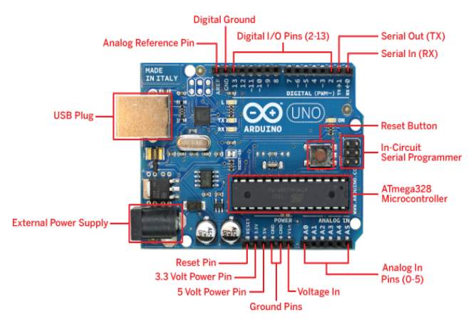
Figure 4: Arduino UNO Board
3.3 L293D
DC Motor Driver is a L293D based motor driver interface board from AB Lab Solutions. The main aim of interfacing DC motor with any microcontroller is to control the direction and speed of a DC motor. But due to high voltage and current requirement of DC motors, it cannot be interfaced directly with microcontrollers. For to interface DC motor with any microcontroller, we need a motor driver. Motor driver is basically a current amplifier which takes a low-current input signal from the Arduino Microcontroller ATmega328p and gives out a high current signal i.e current Amplified signal which can control and drive the motor. L293D is a dual H-Bridge motor driver IC. With one L293D IC we can interface two DC motors which can be controlled in both clockwise and counter clockwise direction.
Figure 5: L293D Motor Driver Circuit
3.4 Servo Motor
A servo engine is an electrical gadget which can push or turn a protest with incredible exactness. To turn a question at some particular edges or separation, servo engine is utilized. It is quite recently comprised of straightforward engine which goes through servo system. On the off chance that engine deals with DC input , it is called DC servo engine, and on the off chance that it takes a shot at AC control, it is called AC servo engine. We can get a high torque servo engine in a little and light weight bundles. for to these reasons they are utilized as a part of numerous applications like toy auto, RC helicopters and planes, Robotics, CNC Machine and so forth. The position of a servo engine is chosen by electrical heartbeat and its hardware is Arranged to the engine.
3.4.1 Working standard of Servo Motor
A servo comprises of a Motor (DC or AC), a potentiometer, outfit get together and a controlling circuit. To start with , we utilize adapt gathering to lessen RPM(Rotation Per Minute) and to expand the torque of engine. At beginning position of servo engine shaft, the position of the potentiometer handle is with the end goal that there is no electrical flag produced at the yield port of the potentiometer.
Presently an electrical flag is given to another info terminal of the mistake locator speaker. The contrast between these two signs , where one originates from potentiometer and another originates from other source, will be prepared as input system and yield will be given as far as blunder flag.
This mistake flag goes about as the contribution to engine and engine begins pivoting. Presently engine shaft is associated with potentiometer and as the engine pivots, it will produces flag. As the potentiometer’s rakish position changes, its yield criticism flag changes. After at some point the position of potentiometer ranges at a position that the yield of potentiometer is same as outer flag gave. At this condition, there will be no yield motion from the speaker to Servo Motor
A servo engine is an electrical gadget which can push or turn a protest with incredible exactness. To turn a question at some particular edges or separation, servo engine is utilized. It is quite recently comprised of straightforward engine which goes through servo system. On the off chance that engine deals with DC input , it is called DC servo engine, and on the off chance that it takes a shot at AC control, it is called AC servo engine. We can get a high torque servo engine in a little and light weight bundles. for to these reasons they are utilized as a part of numerous applications like toy auto, RC helicopters and planes, Robotics, CNC Machine and so forth. The position of a servo engine is chosen by electrical heartbeat and its hardware is Arranged to the engine.
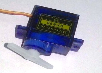
Figure 6: Servo Motor(external view)
3.4.2 Controlling Servo Motor
Servo engine is controlled by PWM (Pulse with Modulation) which is given by the control wires. There is a base heartbeat, a greatest heartbeat and a reiteration rate. Servo engine can turn 90 degree from either course frame its unbiased position. The servo engine hopes to see a heartbeat each 20 milliseconds (ms) and the length of the beat will decide how far the engine turns. For instance, a 1.5ms heartbeat will make the engine swing to the 90 position, for example, if heartbeat is shorter than 1.5ms shaft moves to 0 and on the off chance that it is longer than 1.5ms than it will turn the servo to 180.
Servo engine chips away at PWM (Pulse width regulation) rule, implies its point of pivot is controlled by the length of connected heartbeat to its Control PIN. Essentially servo engine is comprised of DC engine which is controlled by a variable resistor (potentiometer) and a few riggings. Fast compel of DC engine is changed over into torque by Gears. We realize that WORK= FORCE X . Remove, in DC engine Force is less and separate (speed) is high and in Servo, constrain is High and separation is less. Potentiometer is associated with the yield shaft of the Servo, to figure the point and stop the DC engine on required edge. Servo engine can be pivoted from 0 to 180 degree, yet it can go up to 210 degree, contingent upon the assembling. This level of turn can be controlled by applying the Electrical Pulse of appropriate width, to its Control stick.
Servo checks the beat in each 20 milliseconds. Beat of 1 ms (1 millisecond) width can turn servo to 0 degree, 1.5ms can pivot to 90 degree (unbiased position) and 2 ms heartbeat can turn it to 180 degree.
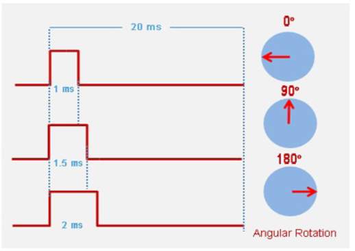
Figure 7: Controlling of Servo Motor –shaft motion (PWM)
3.5 Stepper Motor
A stepper engine is a sort of DC engine which has a full turn isolated in an equivalent number of steps. It is a sort of actuator very perfect with numerical control implies, as it is basically an electromechanical converter of computerized motivations into corresponding development of its pole, giving exact speed, position and bearing control in an open-circle mold, without requiring encoders, end-of-line switches or different sorts of sensors as regular electric engines require. he ventures of a stepper engine speak to discrete rakish developments, that happen in a progressive mold and are equivalent in uprooting, when working effectively the quantity of steps performed must be equivalent to the control driving forces connected to the periods of the engine. The last position of the rotor is given by the aggregate rakish dislodging coming about because of the quantity of steps performed. This position is kept until another drive, or arrangement of motivations, is connected. These properties make the stepper engine a phenomenal execution component of open-circle control frameworks. A stepper engine does not lose steps, i.e. no slippage happens, it stays synchronous to control driving forces even from halt or when braked, on account of this trademark a stepper engine can be begun, ceased or switched in a sudden manner without losing ventures all through its operation.

Figure 8: Stepper Motor(from CD drive)
Chapter 4 - SOFTWARE
4.1 Introduction
Designing as a teach regularly requires more coordination than a lot of unique advancement. In a regular venture, composing new code presents critical difficulties, and the quantity of elements shared between tasks implies that it is conceivable to make shared parts which actualizes basic elements. A library or a current module permits the utilization of a very much created and a tried part, which spares noteworthy assets in the execution of the venture .The disadvantage of segments is the need to coordinate different possibly clashing interfaces and the need to comprehend an unpredictable framework with a specific end goal to viably utilize the segment.
Segments can be acquired, or might be uninhibitedly accessible, as on account of Open Source programming. Open Source additionally gives the chance to contribute new components and bug settles back into the group. The projects and instruments we decided for this venture are all open source, and utilize global measures, which permitted to quickly build up the elements required.
The venture programming framework comprises of:
- Inkscape.lnk
- CAMotics-1.0.6
- Arduino IDE
- Processing 3.2.4
4.2 Inkscape.Ink
There are two essential sorts of realistic pictures: bitmap (or raster) pictures and vector pictures .In the primary case, the picture is characterized as far as lines and sections of individual pixels, each with its own particular shading. In the second case, the picture is characterized regarding lines, both straight and bended. A solitary straight line is portrayed as far as its two end focuses.
The distinction in these sorts of realistic pictures turns out to be promptly obvious when a drawing is broadened. A similar line is appeared on the left and right. On the left it is shown as a bitmap picture, while on the correct it is shown as a vector. In both cases, the line has been scaled up by a component of four from its ostensible size.
At the point when the bitmap determination of a drawing matches the show determination, the items in the drawing look smooth. A similar drawing, however characterized as a bitmap picture on the left and a vector picture on the privilege. On the off chance that the yield gadget has an indistinguishable determination from the bitmap picture, there is little contrast between the presence of the two pictures.
In the event that the bitmap determination is fundamentally not as much as the show determination, the show will demonstrate rough lines. The leader of the noble man in the above drawings has been scaled up by a component of five. Presently one can see a distinction in the nature of the bitmap drawing (left) and the vector drawing (right). Take note of that the bitmap picture utilizes hostile to associating, a technique for utilizing grayscale to endeavor to smooth the drawing.
All yield gadgets, with couple of special cases, utilize a raster or bitmap picture to show representation. The genuine contrast between drawing with bitmap representation and vector illustrations is the time when the picture is changed over into a bitmap. On account of vector design, this transformation is done at the last stride before show, guaranteeing that the last picture coordinates precisely the determination of the yield gadget.
4.2.1 Scalar Vector Graphics (SVG)
SVG remains for Scalable Vector Graphics. Versatile alludes to the idea that an attracting can be scaled to a discretionary size without losing point of interest. Versatile additionally alludes to the possibility that a drawing can be made out of a boundless number of littler parts, parts that can be reused ordinarily. The SVG standard is coordinated toward a total portrayal of two-dimensional design, incorporating activity in a XML (extensible Markup Language) arrange. XML is an open standard for depicting a report in a way that can be effortlessly stretched out and is impervious to future changes in the record determination. An attracting spared one adaptation of SVG by one form of a drawing system ought to be distinguishable, to the full degree conceivable, by any past or future variant of any attracting program that holds fast to the SVG standard. In the event that a program doesn’t bolster something in the SVG standard, it ought to simply skirt any piece of a drawing that utilizations it, rendering the rest effectively.
SVG documents are little, and drawings portrayed by the standard adjust well to various introduction strategies. This has prompted extraordinary enthusiasm for the standard. Support is incorporated into many web programs (Firefox, Chrome, Opera, Safari, and Internet Explorer from variant 9),or is accessible through attachment ins(e.g.,[Adobe[http://www.adobe.com/svg/watcher/introduce/,SsrcSVG[http://www.savarese.com/programming/svgplugin/]and Google [http://www.google.com/chrome frame]). Over twelve organizations including Apple (iPhone), Blackberry, LG, Motorola, Nokia, Samsung, and Sony Ericsson create cell phones that use a subset of the full SVG standard (SVG Tiny) that has been custom fitted for gadgets with constrained assets.
Inkscape is a free and open-source vector representation proofreader; it can be utilized to make or alter vector design, for example, delineations, graphs, line expressions, diagrams, logos and complex works of art. Inkscape’s essential vector representation organization is Scalable Vector Graphics (SVG) variant 1.1. While Inkscape can import and fare a few arrangements, all altering work process unavoidably happen inside the rules of the SVG design.
Inkscape can render primitive vector shapes (e.g. rectangles, ovals, polygons, bends, spirals, stars and isometric boxes), content and locales containing raster design. It likewise bolsters picture following, empowering the supervisor to make vector representation from photographs and other raster sources. Made shapes can be subjected to further changes, for example, moving, turning, scaling and skewing. These items might be loaded with strong hues, designs, brilliant or direct shading angle, their fringes stroked or their straightforwardness changed.
Inkscape SVG-based vector drawing project is valuable for drawing:
- Illustrations for the Web
- Graphics for cell phones
- Simple line drawings
- Cartoons
- Complex masterpieces
- Figures for articles and books
- Organization graphs
- Designs
The document arrange that Inkscape uses is minimal and rapidly transmittable over the Internet. However it is intense and can depict complex drawings that are versatile to any size. Bolster for the organization has been added to web programs and is now incorporated into numerous cell phones.
Inkscape bolsters the drawing of general shapes (rectangles, circles, and so forth.), subjective ways, and content. These items can be given a wide assortment of qualities, for example, shading, angle or designed fills, alpha mixing, and markers. Items can be changed, cloned, and gathered. Hyperlinks can be included for use in web programs. The Inkscape program intends to be completely XML, SVG, and CSS agreeable.
Inkscape is accessible prepackaged for the Windows, Macintosh, and Linux working frameworks. The program and its source code are openly accessible. They can be gotten from the Inkscape site [http://www.inkscape.org/]. Inkscape is experiencing extremely fast advancement with new components being added and consistence to the SVG standard being always moved forward.
4.2.2 Inkscape Window
Begin by opening Inkscape .This window contains a few noteworthy zones, many containing interactive symbols or draw down menus. The accompanying figure demonstrates this window and names key parts.
The Command Bar, Snap Bar, Tool Controls, and Tool Box are separable by delaying the handles (highlighted in blue) at the far left or top. They can be come back to their typical place by dragging them back. New in v0.48: Some of the bars change position contingent upon which alternative is chosen at the base of the View menu. At the point when Default is chosen, the Command Bar is on the top while the Snap Bar is on the privilege. At the point when Custom is chosen, the Command Bar and the Snap Bar are both on the top. At the point when Wide is chosen, the Command Bar and the Snap Bar are both on the privilege. Of course, Default is utilized in the event that you are not utilizing a Wide Screen” show while Wide is utilized on the off chance that you are. A width to stature viewpoint proportion of more prominent than 1.65 is characterized to be wide. These bars, and also the Palette and Status Bar, can be shrouded utilizing the View Show/Hide submenu.
As Inkscape has developed more mind boggling, the region required to incorporate symbols and passage boxes for all the different things has additionally developed prompting issues when Inkscape is utilized on little screens. The Command Bar, Snap Bar, Tool Controls, and Tool Box have variable widths or statures. In the event that there are an excessive number of things to be appeared in the width (tallness) of the Inkscape window, a little down bolt will show up on the correct side or base of the bars. Tapping on this bolt will open a drop-down menu with access to the missing things.
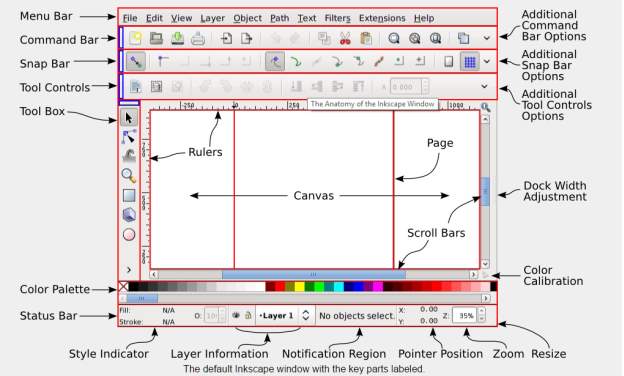
Figure 9: Inkscape Window
4.2.3 Inkscape Program
Inkscape has its foundations in the program Gill (GNOME Illustrator application) made by Raph Levian [http://www.levien.com/] of Ghostscript notoriety. This venture was developed by the Sodipodi [http://sourceforge.net/ventures/sodipodi] program. An alternate arrangement of objectives prompted the split-off of the current Inkscape advancement exertion.
The objective of the authors of Inkscape is to deliver a program that can take full favorable position of the SVG standard. This is not a little undertaking. A connection to the guide for future advancement can be found on the Inkscape site [http://www.inkscape.org/].
Directions on introducing Inkscape can be found on the Inkscape site. Full usefulness of Inkscape requires extra aide projects to be introduced, particularly to import and sending out records in various realistic arrangements.
In this venture the utilization of inkscape is to change over any image(formats) into representation code normally known as GCODE. .GCODE configurations are created by coordinating inkscape with essential expansion documents.
4.2.4 Generating Gcode records utilizing inkscape
- Download and introduce Inkscape 0.48.5 rendition.
- Install an Add-on that empowers the fare pictures to gcode records.
- Open the Inkscape, go to File menu and snap “Report Properties”.
- Change the custom size.
- Now close this window.
- Open the required picture.
- Re-estimate the picture to fit our printing range.
- Click Path from menu and “Follow Bitmap” ,Make required changes.
- Click alright and close the window.
- Now, move the dark scale picture, and erase the shading one behind it. Move the dark picture to the right place again and click from Path menu “Protest way”.
- Final, go to record menu, click spare as and select .gcode. Click alright on next window.
GCode Tools:
Gcodetools is an open source Inkscape augmentation, to trade gcode for use with a CNC machine, written in the Python programming dialect. Inkscape augmentations work in the standard Unix IO display, taking SVG on standard information, and yield changed SVG on standard yield. The Gcodetools augmentation creates G-Code from the SVG input and composes it to a record as a symptom of the SVG change. This python augmentation can be effortlessly downloaded as a .ZIP document from https://github.com/martymcguire/inkscape-unicorn
4.3 CAMotics
CAMotics is an Open-Source programming which recreates 3-pivot CNC processing or etching. It is a quick, adaptable and easy to understand recreation programming for the DIY and Open-Source people group. CAMotics takes a shot at Linux, OS-X and Windows.
Having the capacity to reenact is a basic piece of making CNC instrument ways. Programming a CNC without a test system is cutting without measuring; it’s both hazardous and costly. With CAMotics we can review the aftereffects of your cutting operation before you _re up your machine. This will spare the time and cash and open up a universe of imaginative conceivable outcomes by permitting us to quickly envision and enhance plans without squandering material or breaking devices.
At home assembling is one of the following huge innovation insurgency There have been real advances in desktop 3D printing (e.g. Creator Bot) yet take-up of desktop CNCs has slacked in spite of the accessibility of modest CNC machines. One of the significant purposes behind this is an absence of Open-Source reenactment and CAM (3D model to instrument way transformation) programming. CAM and NC machine reproduction exhibit some extremely troublesome, yet not unrealistic, programming challenges. While, 3D printing recreation and apparatus way era are substantially less demanding.
CAMotics plans to be a helpful CNC recreation stage for the DIY and Open-Source people group. CAMotics ought to serve the exceptionally specialized client yet stay straightforward and easy to understand enough to bolster less geek sorts also.
Highlights
- Fast 3-hub cut-workpiece reproduction with 3D perception.
- Simulates tube shaped, tapered, ballnose, spheroid and snubnose instrument shapes.
- Tool way 3D representation.
- Multi-strung rendering can exploit multi-processor CPUs.
- GCode parsing, recreation, check and explanation.
- Supports LinuxCNC (AKA EMC2) O-codes.
- Export slice workpiece to STL document.
- Tool table altering.
- Add tallness examining to 2D GCode records. Exceptionally valuable for circuit board cutting and metal etching.
- 2D GCode way improvement.
- Operates in Windows and Linux.
- Released under the GPL v2+ permit.
Constraints
- Simulates just previews of the cutting procedure.
- No 5-hub reproduction.
- No Lathe recreation.
- No CAM offices yet, e.g. 3D model to apparatus way transformation.
- No CNC machine control, not a substitution for LinuxCNC or MACH3.
- Does not yet identify over/under cutting, crashes with the apparatus shaft or installations or quick moves in the material.
- Not the majority of the LinuxCNC G-Code dialect is actualized, yet.
4.4 Arduino IDE
The Arduino extend gives the Arduino coordinated advancement condition (IDE), which is a cross-stage application written in the programming dialect Java. It started from the IDE for the dialects Processing and Wiring. It is intended to acquaint programming with specialists and different newcomers new to programming advancement. It incorporates a code manager with elements, for example, language structure highlighting, prop coordinating, and programmed space, and gives basic a single tick component to aggregate and load projects to an Arduino board. A program composed with the IDE for Arduino is known as an “outline”.
The Arduino IDE bolsters the dialects C and C++ utilizing extraordinary principles to sort out code. The Arduino IDE supplies a product library called Wiring from the Wiring venture, which gives numerous basic information and yield techniques. A run of the mill Arduino C/C++ draw comprise of two capacities that are assembled and connected with a program stub principle() into an executable cyclic official program:[.2cm]
- setup(): a capacity that runs once toward the begin of a program and that can introduce settings.
- loop(): a capacity called over and over until the board controls off.
Subsequent to aggregating and connecting with the GNU toolchain, likewise included with the IDE appropriation, the Arduino IDE utilizes the program avrdude to change over the executable code into a content document in hexadecimal coding that is stacked into the Arduino board by a loader program in the board’s firmware.
4.5 Processing 3.2.4
Handling is a straightforward programming condition that was made to make it less demanding to grow outwardly situated applications with an accentuation on liveliness and giving clients moment criticism through communication. The engineers needed a way to ‘portray” thoughts in code. As its abilities have extended over the previous decade, Processing has come to be utilized for more propelled generation level work notwithstanding its portraying part. Initially worked as a space particular expansion to Java focused towards craftsmen and architects, Processing has advanced into an out and out plan and prototyping instrument utilized for huge scale establishment work, movement design, and complex information perception.
Handling depends on Java, but since program components in Processing are genuinely basic, you can figure out how to utilize it regardless of the possibility that you don’t have the foggiest idea about any Java. In case you’re comfortable with Java, it’s best to overlook that Processing has anything to do with Java for some time, until you get the hang of how the API functions. The most recent form of Processing can be downloaded at http://processing.org/download.
A critical objective for the venture was to make this sort of programming open to a more extensive gathering of people. Consequently, Processing is allowed to download, allowed to utilize, and open source. Be that as it may, ventures created utilizing the Processing condition and center libraries can be utilized for any reason. This model is indistinguishable to GCC, the GNU Compiler Collection. GCC and its as sociated libraries (e.g. libc) are open source under the GNU Public License (GPL), which stipulates that progressions to the code must be made accessible. Be that as it may, programs made with GCC (cases excessively various, making it impossible to specify) are not themselves required to be open source.
Preparing comprises of:
- The Processing Development Environment (PDE). This is the product that runs when you double tap the Processing symbol. The PDE is an Integrated Development Environment (IDE) with a moderate arrangement of components outlined as a straightforward prologue to programming or for testing one-off thoughts.
- A gathering of capacities (likewise alluded to as orders or strategies) that make up the “center” programming interface, or API, and also a few libraries that bolster more propelled components, for example, sending information over a system, perusing live pictures from a webcam, and sparing complex symbolism in PDF design.
- A dialect grammar, indistinguishable to Java however with a couple of adjustments.
- An dynamic online group, based at http://processing.org.
4.5.1 Sketching with Processing
A Processing project is known as a portray. The thought is to make Java-style programming feel more like scripting, and receive the way toward scripting to rapidly compose code. Representations are put away in the sketchbook, an organizer that is utilized as the default area for sparing the greater part of your ventures. Draws that are put away in the sketchbook can be gotten to from File Sketchbook. On the other hand, File Open… can be utilized to open an outline from somewhere else on the framework. Propelled software engineers require not utilize the PDE, and may rather utilize its libraries with the Java condition of decision. In any case, for a tenderfoot, it’s prescribed to utilize the PDE to pick up recognition with the way things are finished. While Processing depends on Java, it was never intended to be a Java IDE with preparing wheels. The reasonable model (how programs work, how interfaces are manufactured, and how records are taken care of) is to some degree not the same as Java.
Figure 10: Processing 3.2.4 Window
Chapter 5 - INDUSTRIAL DESIGN
5.1 Introduction
The complete mechanical setup was designed by using Aluminium and Fiber sheets which are insulated from currents.
The designs in the project are
- X-Y Direction.
- Pen setup.
- Aluminium Stand holder.
- Final Plotter Arrangement
Arrangement of Axis
X-axis is parallel to the base which moves towards north and south directions.
Y-axis is perpendicular to the X-axis and moves towards left and right directions.
Z-axis is arranged to Y axis operated by Servo motor shaft which moves in upwards and downwards ,i.e. up and down movement of pen to plot.
5.2 X Axis and Y-Axis
CD Drive, it is an optical disc drive which uses laser light or electromagnetic waves for communicating i.e retrieving and writing on to the discs within the visible light spectrum. Earlier drives are only reading discs where once the data is written it cannot be erasable i.e Non Volatile memory, but now a days drives can do both read and write operations i.e Volatile memory, they are also called burners/writers. Compact discs, DVDs, and Blue-ray discs are common types of optical media which can be read and written Optical discs are reaching to lowers production because of advancements in technology .CD-ROM drive, CD writer drive, and combo (CD-RW/DVD-ROM) drives are not in use as of now but were popular in past. The most popular drive used at present is DVD writer drive mainly used for desktop PCs and laptops. There are also many DVD types used in present for copters like the DVD-ROM drive, BD-ROM drive, Blue-ray Disc combo (BD-ROM/DVDRW/CD-RW) drive, and Blue-ray Disc writer drive.
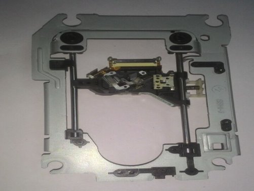
Figure 11:CD Drive with Stepper Motor
5.3 Aluminium Stand holder
The stand holding all the parts are made by the Aluminium and fiber sheets . Aluminium sheets are welded together perpendicularly for holding the x and y axis.
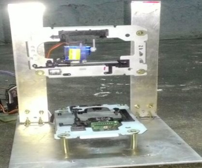
Figure 12: Aluminium stand
5.4 Pen Setup (Z-axis)
For pen setup i.e. Z axis Fiber sheet is used. It is a type of fiberboard, which is an petroleum by product. It is of light weight which makes the servo motor ease to lift it..Servomotor is arranged to Y axis parallel to the fiber holder in such a way that it holds the pen setup by servo motor shaft. so that the up and done motion of pen is carried to plot the design of SVG given to the stepper motors.
5.5 Final Setup
All the sections are integrated together in an arrangement which produces the perfect expected output by mechanical settings.
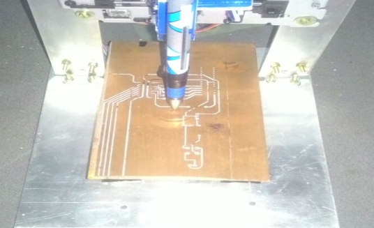
Figure 13: Pen setup
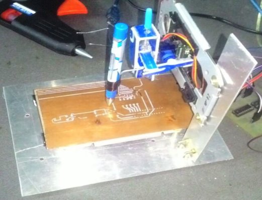
Figure 14: side view
Chapter 6 - PROJECT IMPLEMENTATION
6.1 Introduction
The accompanying strides demonstrates the building phases of a minimal effort smaller than normal CNC plotter. the stepper engines from CD drive are utilized for X and Y pivot. Servo motor is used for z axis for the movement of writer(pen). Inkscape, Processing and Arduino IDE gives the instructions from the computer as gcode to the Arduino board to get the plotted output.
Major Block Diagram
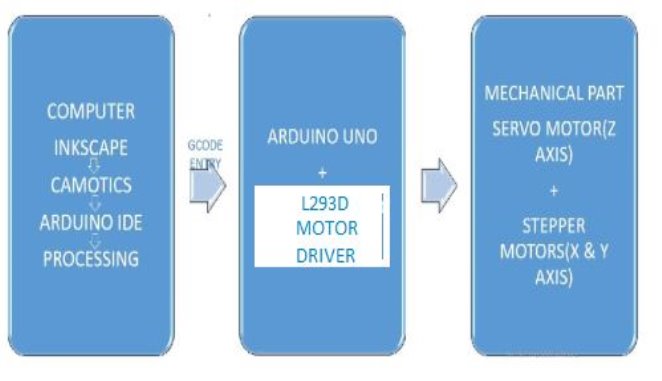
Figure 15: Major Block Diagram
6.2 Steps Involved in the Project
Step 1- Design of project hardware
- First stage to begin assembling this CNC machine is to dismantle two DVD/CD drives and remove the stepper motors setup with frame from them.
- The aluminium sheets are for flexible holdings ,two sheets are welded perpendicularly to make the stand holding for x and y axis.
- Arrange the CD drive stepper motor setup as x and y axis. keep the X axis straight to CNC base i.e parallel and the Y axis vertically i.e. perpendicularly to the base.
- Z axis (pen setup) is attached to the Y axis. The pen setup is made up of fiber sheet , the servo motor is fixed to it and the pen is setup inside the fiber using a screw or by sticking using glue gun.
- A metallic base is attached to the X axis for to use as base where a paper is kept for drawing on it. Then a paper is put above it with the help of some magnets or paper clips. The printing area is 25x25mm.
Step 2-Arduino IDE and Stepper Motor Setup
- The L293D motor driver circuit compatible with the Arduino board is connect to it by serial communication via copper cables.
- The Arduino is connected the computer, where it gets gcode for executing step by step.
- Check the working status of stepper motors and the servo motor.
- The stepper motors and the servo motor are connected to the motor driver circuit for operation with feasible currents.
- The external power of 5v is given via Adapter .(Trainer Kit 5v,200-500mA)
Step 3-booting of Arduino Program and Gcode via serial communication
- The mini CNC plotting sketch is dumped to the Arduino microprocessor (ATmega328p) by using Arduino IDE.
- Gcode is made by Inkscape program.
- Then utilize the gctrl.pde preparing program. This program sends “gcode” pictures called as SVG(Scalable Vector Graphics) to the CNC plotter.
- Plotting of the image on paper is done according to gcode instructions given via processing software.
6.3 Result
Integrating the software along with the hardware using mechanical systems gives up an effective CNC plotter.
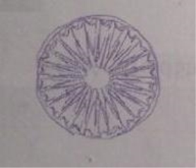
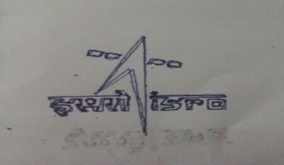
Figure 16: Plotted Output Images
Applications
Metal Removal Applications
CNC machines are widely utilized as a part of ventures where metal expulsion is required. The machines expel overabundance metal from crude materials to make complex parts. A decent case of this would be the car enterprises where riggings, shafts and other complex parts are cut from the crude material. CNC machines are additionally utilized as a part of the assembling businesses for delivering rectangular, square, adjusted and even strung employments. All procedures, for example, processing, granulating, turning, exhausting, reaming, and so on, can be controlled and done by these CNC machines utilizing particular machine instruments for each undertaking.
Metal Fabrication Industry
Many ventures require thin plates for various purposes. These enterprises utilize CNC machines for various machining operations, for example, plasma or fire cutting, laser cutting, shearing, shaping and welding to make these plates. CNC plasma or laser cutters are utilized for forming metal, while CNC turret presses are utilized for operations like punching gaps. Different operations like twisting metal plates can likewise be completed with high accuracy utilizing CNC squeeze brakes.
Electrical Discharge Machining Applications
Electrical Discharge Machines, or EDMs as they are additionally known, expel metal from the crude material by delivering flashes that copy away the overabundance metal. EDM machining through CNC robotization is done in two diverse routes; first through Wire EDM and second through Vertical EDM.CNC computerized Wire EDM is utilized to punch and after that kick the bucket mixes for making bite the dust sets utilized as a part of the manufacture business. CNC computerized Vertical EDM requires a terminal in an indistinguishable size and shape from the cavity that should be cut out.
PCB Mill (Future)
A PCB Mill is a gadget that engravings out an example on a copper clad board with the end goal that it makes a Printed Circuit Board (PCB). PCBs are utilized wherever in the field of electrical building to interface electrical segments to each other. Regularly, after a board is composed, the format records are sent to a maker who then makes the board and ships it back to the client. While prototyping, the postponement and setup costs related with sending a format to a maker can regularly mean days of down time. While this may not appear to be expensive at to begin with, it can turn out to be to be a huge irritation since most sheets contain a wiring bug that was disregarded or misjudged and should then be changed.
Conclusion
In current CNC frameworks, end-to-end part configuration is profoundly computerized utilizing PC supported plan (CAD) and PC helped producing (CAM) programs. The projects deliver a PC _le that is deciphered to remove the summons expected to work a specific machine by utilization of a post processor, and afterward stacked into the CNC machines for generation. Since a specific part may require the utilization of various diverse instruments – drills, saws, and so on., present day machines regularly consolidate different apparatuses into a solitary “cell”. In different establishments, various distinctive machines are utilized with an outside controller and human or mechanical administrators that move the part from machine to machine. In either case, the arrangement of steps expected to deliver any part is exceptionally robotized and produces a section that intently coordinates the first CAD outline.
We could create a machine that performed all around ok to meet our objectives for exactness, cost, and due date. We began at an opportune time the equipment which permitted us to work through a portion of the issues we experienced, for example, expecting to redesign our engines for the x and y-tomahawks and rewiring our engine driver circuits. This decreased the hazard related with equipment prototyping which was by a long shot the most astounding danger some portion of our venture. We were likewise ready to execute the majority of the vital parts of our machine a little while before our venture due date. We needed to cut a couple of our additional components to meet our due date, for example, a positional criticism framework and a programmed instrument changer, yet we were fruitful in light of the fact that we organized these elements and took a shot at the fundamentals first. Our prosperity can without much of a stretch be credited to the arranging and organizing we did before starting the venture. We cleared out ourselves room in our calendar for surprising postponements and started our venture early. These variables added to an effective venture which started in the arranging stage and finished with a deliverable item which meets the desires we set for ourselves
References
1. Advertisement. Home Improvement Made Easy with New Lower Prices | Improve & Repair with The Home Depot. Web. 25 Apr. 2011.htt://www.homedepot.com.
2. ATmega48A/48PA/88A/88PA/168A/168PA/328/328P Datasheet, Atmel Corporation, Aug. 2010,http://www.atmel.com/dyn/resources/prod_documents/doc8271.pdf.
3. Closed, Soldering Sj2. “Easy Driver Stepper Motor Driver.” SchmalzHaus.com Brian Schmalz Homepage. Web. 08 Apr. 2011.http://www.schmalzhaus.com/EasyDriver.
4. CNC Machine Manufacturers. Photograph. Review about CNC Machine. Web. 25 Apr. 2011.http://www.cncmachine-details.info/cnc-machine-manufacturers.html.
5. “Design Fundamentals for Phototransistor Circuits.” Fairchild Semiconductor, 30 Apr. 2002. Web. 25 Apr. 2011.https://www.fairchildsemi.com/application-notes/AN/AN-3005.pdf.
6. “EMC2 Documentation.” Enhanced Machine Controller Project. Web. 25 Apr. 2011. http://www.linuxcnc.org/docs/html.
7. “Inkscape User Documentation.” Inkscape. Draw Freely. Web. 04 May 2011. https://inkscape.org/en/doc/index.html?lang=en.
8. “Scalable Vector Graphics (SVG) 1.1 (Second Edition).” World Wide Web Consortium (W3C), 22 June 2010. Web. 25 Apr. 2011.https://www.w3.org/TR/SVG11/.
9. “Standard Cataloged Acme Inch Screw and Nut Quick Reference Char –Nook Industries, Inc. Power Acme Screws and Nuts.” Nook Industries : Linear Actuators for Motion Control Ball Screws, Screw Jacks, Lead Screws, Linear Slides, Acme Screw, Actuator. 25 Apr. 2011.http://www.nookindustries.com/Product/ProductLine/Acme-and-Lead-Screw-Products.
Bibliography
Venkatram Ramachandran, Evaluation of Performance Criteria of CNC Machine Tool Drive System, IEEE Transactions on Industrial Electronics, Vol. 45, No. 3, June 1998, pp. 462-468.
Jae Wook Jeon and Young Youl Ha, A Generalized Approach for the Acceleration and Deceleration of Industrial Robots and CNC Machine Tools, IEEE Transactions on Industrial Electronics, Vol. 47, No. 1, February 2000, pp. 133-139.
Allen G. Morinec, Power Quality Considerations for CNC Machines: Grounding, IEEE Transactions on Industrial Electronics, Vol. 38, No. 1, January/February 2002, pp. 3-11.
Dr M Shivakumar, Stanford Michahail, Ankitha Tantry H, Bhawana C K, Kavana H and Kavya V Rao, Robotic 2D Plotter, International Journal of Engineering and Innovative Technology (IJEIT), Volume 3, Issue 10, April 2014, pp.300-303.
Venkata Krishna Pabolu et al., Design and Implementation of a Three Dimensional CNC Machine (IJCSE) International Journal on Computer Science and Engineering Vol. 02, No. 08, 2010, pp. 2567-2570.
Mrs. R. Dayana, Gunaseelan P, Microcontroller Based X-Y Plotter, International Journal of Advanced Research in Electrical, Electronics and Instrumentation Engineering, Vol. 3, Special Issue 3, April 2014.
Ahn Luong, Willis Lutz, Jared Springle, Ashton Snelgrove, Computer numerical control 3 axis plotter, University of Utah, Computer Engineering.
Hassam Salamah, Ja’far Yasin, PCB CNC Machine, An-Najah national University, Computer Engineering.
W Durfee, Arduino Microcontroller Guide, University of Minnesota.
Steve Krar, Arthur Gill, Computer Numerical Control Programming Basics.
Instuctables.com
Wikipedia.com
Cite This Work
To export a reference to this article please select a referencing stye below:
Related Services
View all


Related Content
All TagsContent relating to: "Computing"
Computing is a term that describes the use of computers to process information. Key aspects of Computing are hardware, software, and processing through algorithms.
Related Articles

DMCA / Removal Request
If you are the original writer of this dissertation and no longer wish to have your work published on the UKDiss.com website then please: