Dissimilar Joint of Ferritic and Austenitic Stainless Steels Evalution
Info: 5076 words (20 pages) Dissertation
Published: 9th Dec 2019
Tagged: EngineeringPhysics
Abstract
Nowadays, dissimilar joint of ferritic and austenitic stainless steels have attracted the attention of many researchers. Because these dissimilar joints increase their efficiency and reduce the costs. In this regard, conventional fusion welding techniques seem inappropriate due to problems such as grain growth. As a solution to these problems, solid state joints such as friction stir welding can be very useful. For this purpose, effects of FSW parameters such as welding speed, rotational speed, the position of welded materials and offset on dissimilar austenitic (AISI 304L)-ferritic (AISI 430) stainless steel joints were studied. Microstructure studies show the presence of distinet regions of SZ and TMAZ. Microstructure refining occurred due to the occurrence of dynamic recrystallization. The microstructure severely refined in the ferritic side of the weld. The result of the phase investigations showed that no carbids and brittle phase were detected at the joint zone. Also, tensile test results demonstrate that the highest tensile strength was obtained at 1mm offset toward ferritic stainless steel. In addition, the highest microhardness was measured in the stir zone of ferritic stainless steel, which can attribute to the decrease in the grain size.
Keywords: Dissimilar joints, Ferritic Stainless steel, Austenitic Stainless steel Friction stir welding.
Introduction
The importance of dissimilar joints has increased in all aspects of production due to increased efficiency, improved service performance, reduced cost and weight.Some of these industries include Aerospace, automotive, oil and gas, petroleum, petrochemical, nuclear and thermal power plants [1-5]. Stainless steels are a group of engineering materials that have been used extensively for their properties such as corrosion resistance, physical and mechanical properties [6, 7]. Among the various types of stainless steels, austenitic and ferrite types are one of the most widely used ones. Ferritic stainless steels exhibit good ductility, formability, and moderately better yield strength relative to those of the austenitic grades, but the high temperature strength is somewhat poor [8]. Grain growth and martensite formation are the problems of ferritic stainless steels welding. But austenitic stainless steels are more weldable [9]. However, replacing austenitic stainless steel with ferrite can be beneficial in terms of cost savings and increased performance. dissimilar joints of these materials is used in TiCl4 reduction retorts [10], heat exchangers [11] and railway and road transport industries [12]. Nevertheless, the welding of austenitic steels to ferrite due to the lack of coordination in the expansion of thermal expansion and undesirable metallurgical changes leads to crack formation in the weld area [13, 14]. Therefore, choosing the type of welding process is very important. In this regard, some researchers have used fusion welding processes to joint these metals, which encountered problems such as grain growth in heat affected zone, and the formation of martensite and carbide deposition in the boundaries [12, 13, 15-17]. grain coarsening and formation of martensite along the ferrite grain boundaries reduces the strength, ductility and corrosion resistance [18]. With this in mind, the use of processes at low welding temperatures, such as solid state processes, can be effective in solving these problems [19]. Satyanarayana et al. Studied the mechanical and metallurgical properties of AISI304-AISI430 joints by means of a friction welding process [10]. Reddy et al. Also compared the fusion and solid state process in joining of these two materials [20]. According to their study, the use of the solid state process produces better mechanical and microstructure properties than fusion states.
Friction stir welding is one of the solid state processes that was developed in 1991 at the TWI Institute for Aluminum alloys Welding. Over the past two decades, the use of this process for materials with high melting points, such as stainless steels, has attracted the attention of many researchers. Some of them investigated the effect of FSW parameters on the microstructure and mechanical properties of stainless steels [21-24]. In addition, in order to eliminate the problems of fusion welding in dissimilar joints such as formation of brittle intermetallics and low melting point eutectics, the use of the FSW process can be useful [25].
In this study, because of the favorable results in FSW of steels, this process was used for dissimilar joints of austenitic stainless steel to ferrite. The effects of FSW parameter such as material position, traverse speed, rotation speed, and tool offset on the microstructure changes and mechanical properties of joints are evaluated.
Experimental
In present work, AISI 304L austenitic stainless steel and AISI430 ferrites plates with 2 mm thickness, were used. The nominal chemical compositions of these steels are given in Table 1. Both welding specimens were cut into pieces in dimensions of 60×100×2 mm. According to Table 2, Welding was carried out at various ratios of w/v. Visual inspection of the welds surface apparent indicated that, by increasing the /v ratio, the quality of the welds improves. In this way, in the ratio of 4.5 because of the less frictional heat, the flow of materials was not completely carried out. By increasing the ratio of /v to 11.2 due to adequate heat supply, the defects were reduced and the sound weld was obtained. But in ratios above this value, the groove defect was re-formed due to the wear of the pin. Therefore, 560 rpm and 50 mm/min were respectively selected as the optimal parameter for the rotational and transverse speed. In this optimal parameter, the welding quality was tested by placing ferrite stainless steel on retreating side. It was observed by changing the positioning of the material, groove defect is created at the surface. The reason for this, according to Chung et al., Is the softness of ferritic stainless steel compared to austenitic at the welding temperature [26]. Because of this, the best positioning of ferrite stainless steel was detected in AS. After choosing the best ratio, the difference in thermal and mechanical properties of the two materials led to the use of offset in the advanced and retreated side. The zero state is considered when the pin located at the butt line. In accordance with the dimensions of the tool pins, offsets of 0.5, 1 and 1.5 mm were used on both advancing and retreating sides. Table 3 demonstrates the nomenclature adopted in the text for labeling the various welds. The tool was made of Tungsten carbide (WC) with the dimensions specified in Figure 3 was used. The evolution of the microstructure in the cross-section of the joint was evaluated by optical microscopy (OM), Scanning electron microscopy (SEM) and dispersive X-ray spectroscopy (EDS). Specimens were electrolytically etched with solution of 60% nitric acid, 40% Distilled water at 5V. For macroscopic structure, the electrolytically etch of 10% oxalic acid, 90% water was used. X-ray diffraction analysis was selected to study the phases and estimate their percentage in the nugget zone. To determine the mechanical properties of joints, micro hardness and tensile tests were employed. Fig 2 shows the shape and size of the tensile test samples. These dimensions are determined by ASTM-E8 standard.
Result and discussion
The difference in coefficient of friction (COF), thermal diffusivity (α=k/ρCp) and softening characteristics complicates the dissimilar materials joints. The difference in each of these cases can affect the heat profile of the weld center and the flow of the material [27]. The tool offset is a key parameter in the dissimilar joints because it improves material flow and uniformity of heat distribution. For this reason by fixing ferrite stainless steel on the AS and setting the optimal parameter (560rpm, 50mm/min), the tool offset was used on the AS and RS as shown in Fig3. Respectively in samples 1, 2 and 4, defects of the cavity and lack of penetration in the weld root were observed. The high COF of 304 steel prevented the flow of material and the mixing did not occur completely. Nonetheless, the low contact of the tool pins with 304L steel caused crack formation in the roots of the weld (Fig. 3 (g)). However, 3, 5 and 6 samples were sound weld (Fig. 3 (c, e, and f)).
The microstructure study revealed the existence of two distinct regions, SZ and TMAZ for each of the two steel (Fig. 4). Also, there was no evidence for the formation of the HAZ region on either side of the joint. This is due to low heat input in the FSW process. Dynamic recrystallization is considered as the main factor for fine-grained structure in SZ. Dynamic recrystallization was occurring discontinuously (DDRX) or continuously (CDRX). Since with increasing SFE, processes such as cross-slip and climbing dislocations are easily accomplished. Thus, dislocation cell are formed and as a result of the distribution of these dislocations, nucleation occurs. Therefore, in materials with high SFE materials such as ferritic stainless steel, the dominant mechanism will be continuous dynamic recrystallization [28]. Due to the high stacking fault energy of the ferritic stainless steel compared to austenitic type, DDRX and CDRX respectively have occurred in the SZ of the 304L and 430 steel. Saeid et al. also achieved similar results [29]. Nevertheless, it was observed that grain refinement on the ferritic stainless steel side was higher than austenitic (Fig 4 (b and c)). In this regard, Kim and Yoo concluded in their study that the continuous dynamical recrystallization increased with increasing Zener-Hollomon parameter [30].
The comparison of grain size in the SZ region showed that the grains in the pin affected region are much smaller than the shoulder affected region (Fig 4 (تصویر گذاشته شود). Microstructure evolutions are affected by the strain rate (ε°) and temperature (T). The size of the recrystallized grains is obtained from equation 1:
D= (a+b
lnz)-1 (1)
Where the a and b are two constants dependent on the material type and Z is Zener-Hollomon parameter and is obtained from equation 2:
Z = ε° exp(Q/RT) (2)
Where Q and R are activation energy and gas constant, respectively.
According to previous studies, the highest strain rate and the lowest temperature are formed in the pin affected area [31, 32]. Therefore, it can be concluded that the Z parameter was higher in the pin affected area and consequently according to equation 1, the grains were smaller.
Between area SZ and base metal, TMAZ region is located. This area also experiences the temperature and plastic deformation at the same time. However, on the steel side 430, the grain size was smaller in TMAZ than the SZ region (Fig.4 (a)). The low temperature in the TMAZ, coupled with the extreme plastic deformation, may have created these ultra-fine grains. But in the TMAZ region of 304L steel, seeds with a slight deformation were observed relative to the austenitic base metal (Fig.4 (f)).
Also black spots were found in ferritic stainless steel SZ (Fig 4). XRD analysis was used to identify these spots. X-ray diffraction patterns demonstrated that austenite and ferrite are the only phases forming in this region (Fig 5). It was found that these black areas are ferritic ultra-fine grains. The high energy of these points, caused burned during etch. Park et al. also predicted such a structure with the EBSD technique [33].
By using equation (3) and X-ray diffraction patterns, a percentage of austenite and ferrite phases were calculated.
Vγ=[1q∑j=1qIγjRγj][1q∑j=1qIγjRγj]+[1p∑i=1pIαiRαi]
) (3)
Where: p and q, respectively the number of ferrite and austenitic diffracted peaks,
Iγand
Iαare measured from the diffraction pattern whereas
Rαand
Rγare calculated from Eq 4:
(4)
R=1V2[F2P1+cos2θsin2θcosθ]e-2M
Where: V is the volume of the unit cell; F is the structure factor; p is the multiplying factor; θ is the diffraction angle; and
e-2Mis temperature factor. Junior et al. also used the above method to determine the phase percentage [34, 35]. The austenite and ferrite phase percent variation are shown in Fig. It was observed that by changing the tool offset to ferrite stainless steel (from sample 1 to sample 7 except sample 4), the percentage of austenite phase decreases. In sample 4, due to incomplete mixing, the percentage of ferrite phase is higher.
Table 3 shows the variation in the ultimate tensile strength (UTS) of the joint and the fracture locations for various offset. The results showed that samples 1, 2, 4 and 7 were defeated from joint without significant deformation. As mentioned above defects like lack of penetration and cavity have caused such behavior. However, it was observed that in the sample 3, despite the sound weld, failure occurred in the lower strains. A brittle fracture in this case was due to the presence of tungsten carbide particles in stir zone. The presence of these particles was determined by SEM and EDS analysis. High wear on the austenitic stainless steel can be a factor for this issue. Increasing the tensile strength and strain rate in sample 6 is due to the creation of a duplex state. Increasing the properties caused that failure occurs in ferritic base metal.
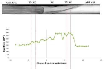
The micro hardness profile at the cross section of the weld showed that various microstructures had different hardness. In the 430 steel base metal, the average hardness was about 187 Hv. The maximum hardness in the TMAZ and SZ regions was about 390 HV and 380 Hv respectively. The refined structure in these two areas is the main reason for increasing hardness. But in 304 steel, the hardness of 204 Hv in the base metal increased to 280 Hv in the SZ region. Due to the fact that grain milling in steel 430 is more than 304, the hardness increases as a result of the Hall-patch relationship [رفرنس صفحه رو بزن].
Conclusion
In this research, it has been tried to achieve successful coupling between austenite and ferrite stainless steel by changing the parameters of friction stir welding, then the effect of these parameters on microstructure and mechanical properties has been investigated. With reviews, it can be concluded that:
- By increasing the /v ratio, the apparent imperfections were reduced and the best welding quality was obtained at a rotational speed of 560 rpm and a transverse speed 50 mm/min.
- The most suitable material for the AS side was 430 steel, which in the opposite case, an imperfection like a groove appeared at the surface of the joint.
- By changing the offset relative to the interaction zone, samples of non-defected microstructures were obtained at 0.5 and 1 mm offset to ferrite stainless steel and 0.5 mm to the austenitic steel.
- The general structure of the weld region consists of three distinct regions, SZ, TMAZ and BM. High strain with a severe plastic deformation led to a dynamic recrystallization of SZ, which resulted in the formation of fine grains in this region. Due to the high SFE in steel 430, continuous dynamic recrystallization resulted in further grain refinement.
- The highest tensile strength was obtained in the 1 mm offset to ferritic steel, in which the austenite and ferrite phase oscillations in the center of the weld became duplex. The presence of tungsten carbide particles in a 0.5 mm offset towards steel 304L was a brittle failure factor.
- The fine grains increased the hardness in the sz and tmaz steel 430 compared to the steel 304.
References
1. Casalino, G., et al., Laser offset welding of AZ31B magnesium alloy to 316 stainless steel. Journal of Materials Processing Technology, 2017. 242: p. 49-59.
2. Jang, C., et al., Mechanical property variation within Inconel 82/182 dissimilar metal weld between low alloy steel and 316 stainless steel. International Journal of Pressure Vessels and Piping, 2008. 85(9): p. 635-646.
3. Kumar, R., A. Bhattacharya, and T.K. Bera, Mechanical and metallurgical studies in double shielded GMAW of dissimilar stainless steels. Materials and Manufacturing Processes, 2015. 30(9): p. 1146-1153.
4. Mittal, R., L. Goyal, and B. Sidhu, METALLURGICAL ASPECTS OF DISSIMILAR METAL WELDMENTS: A Review. 2012.
5. Ramkumar, K.D., et al., Metallurgical and mechanical characterization of dissimilar welds of austenitic stainless steel and super-duplex stainless steel–a comparative study. Journal of Manufacturing Processes, 2015. 19: p. 212-232.
6. Amuda, M. and S. Mridha. Grain refinement in ferritic stainless steel welds: the journey so far. in Advanced Materials Research. 2010. Trans Tech Publ.
7. Maurya, B.K., et al., EXPERIMENTAL ANALYSIS OF DISSIMILAR METAL WELDS OF MILD STEEL AND STAINLESS STEEL. 2017.
8. Amuda, M.O.H. and S. Mridha, An overview of sensitization dynamics in ferritic stainless steel welds. International Journal of Corrosion, 2011. 2011.
9. Özyürek, D., An effect of weld current and weld atmosphere on the resistance spot weldability of 304L austenitic stainless steel. Materials & design, 2008. 29(3): p. 597-603.
10. Satyanarayana, V., G.M. Reddy, and T. Mohandas, Dissimilar metal friction welding of austenitic–ferritic stainless steels. Journal of Materials Processing Technology, 2005. 160(2): p. 128-137.
11. Guilherme, L.H., et al., Corrosion behaviour of a dissimilar joint TIG weld between austenitic AISI 316L and ferritic AISI 444 stainless steels. Welding international, 2016. 30(4): p. 268-276.
12. Pouranvari, M., M. Khorramifar, and S. Marashi, Ferritic–austenitic stainless steels dissimilar resistance spot welds: metallurgical and failure characteristics. Science and Technology of Welding and Joining, 2016. 21(6): p. 438-445.
13. Bina, M.H., et al., Investigation on the resistance spot-welded austenitic/ferritic stainless steel. The International Journal of Advanced Manufacturing Technology, 2014. 75(9-12): p. 1371-1379.
14. Khalifeh, A., A. Dehghan, and E. Hajjari, Dissimilar joining of AISI 304L/St37 steels by TIG welding process. Acta Metallurgica Sinica (English Letters), 2013. 26(6): p. 721-727.
15. Bala Srinivasan, P. and M. Satish Kumar, Characterisation of thin section dissimilar weld joint comprising austenitic and ferritic stainless steels. Materials Science and Technology, 2008. 24(4): p. 392-398.
16. Ghosh, N., P.K. Pal, and G. Nandi, GMAW dissimilar welding of AISI 409 ferritic stainless steel to AISI 316L austenitic stainless steel by using AISI 308 filler wire. Engineering Science and Technology, an International Journal, 2017.
17. Kaul, R., P. Ganesh, and A. Nath, Microstructural characterization of dissimilar laser weld between austenitic and ferritic stainless steels. Journal of Laser Applications, 2005. 17(1): p. 21-29.
18. Silva, C.C., et al., Austenitic and ferritic stainless steel dissimilar weld metal evaluation for the applications as-coating in the petroleum processing equipment. Materials & Design, 2013. 47: p. 1-8.
19. Azizieh, M., et al., Characterizations of dissimilar friction welding of ST37 and CK60 steels. The International Journal of Advanced Manufacturing Technology, 2016. 85(9-12): p. 2773-2781.
20. Reddy, G.M. and K.S. Rao, Microstructure and mechanical properties of similar and dissimilar stainless steel electron beam and friction welds. The International Journal of Advanced Manufacturing Technology, 2009. 45(9-10): p. 875.
21. Bilgin, M.B. and C. Meran, The effect of tool rotational and traverse speed on friction stir weldability of AISI 430 ferritic stainless steels. Materials & Design, 2012. 33: p. 376-383.
22. Kumar, S.S., N. Murugan, and K. Ramachandran, Microstructure and mechanical properties of friction stir welded AISI 316L austenitic stainless steel joints. Journal of Materials Processing Technology, 2018. 254: p. 79-90.
23. Lakshminarayanan, A. and V. Balasubramanian, An assessment of microstructure, hardness, tensile and impact strength of friction stir welded ferritic stainless steel joints. Materials & Design, 2010. 31(10): p. 4592-4600.
24. Meran, C. and O. Canyurt, Friction Stir Welding of austenitic stainless steels. parameters, 2010. 6: p. 13.
25. Jafarzadegan, M., et al., Microstructure and mechanical properties of a dissimilar friction stir weld between austenitic stainless steel and low carbon steel. Journal of Materials Science & Technology, 2013. 29(4): p. 367-372.
26. Chung, Y.D., et al., Interface microstructure evolution of dissimilar friction stir butt welded F82H steel and SUS304. Materials Science and Engineering: A, 2011. 528(18): p. 5812-5821.
27. Kumar, N., R.S. Mishra, and W. Yuan, Friction stir welding of dissimilar alloys and materials. 2015: Butterworth-Heinemann.
28. Cho, H.-H., et al., Microstructural analysis of friction stir welded ferritic stainless steel. Materials Science and Engineering: A, 2011. 528(6): p. 2889-2894.
29. Saeid, T., et al., On the formation of grain structure during friction stir welding of duplex stainless steel. Materials Science and Engineering: A, 2010. 527(24-25): p. 6484-6488.
30. Kim, S.-I. and Y.-C. Yoo, Continuous dynamic recrystallization of AISI 430 ferritic stainless steel. Metals and Materials International, 2002. 8(1): p. 7.
31. Siddiqui, M.A., S. Jafri, and K. Moeed, Effect of process parameters on temperature distribution, strain rate and flow-stress during friction stir welding of aluminium alloy. SIMULATION, 2016. 9(800): p. 6.
32. Meyghani, B., et al. Developing a Finite Element Model for Thermal Analysis of Friction Stir Welding by Calculating Temperature Dependent Friction Coefficient. in 2nd International Conference on Mechanical, Manufacturing and Process Plant Engineering. 2017. Springer.
33. Park, S.H.C., et al. Microstructure and mechanical properties of friction stir welded 430 stainless steel. in The Fifteenth International Offshore and Polar Engineering Conference. 2005. International Society of Offshore and Polar Engineers.
34. Forgas Júnior, A., J. Otubo, and R. Magnabosco, Ferrite quantification methodologies for duplex stainless steel. Journal of Aerospace Technology and Management, 2016. 8(3): p. 357-362.
35. Moser, N.H., T.S. Gross, and Y.P. Korkolis, Martensite formation in conventional and isothermal tension of 304 austenitic stainless steel measured by X-ray diffraction. Metallurgical and Materials Transactions A, 2014. 45(11): p. 4891-4896.
Table 1: Chemical composition of 304L and 430 steel (wt%)
| steel | Ni | Cr | S | P | Mn | Si | C |
| 304L | 7.24 | 17.7 | 0.01 | 0.03 | 0.96 | 0.5 | 0.03 |
| 430 | 0.17 | 15.9 | 0.006 | 0.02 | 0.42 | 0.43 | 0.06 |
Table 2 surface quality of welds in different /v.
| /v | (rpm) | v (mm/min) | Joint appearance | Visual inspection |
| 4.5 | 450 | 100 |  |
Lack of bonding |
| 5.6 | 560 | 100 |  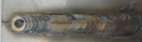 |
Groove defect |
| 7.1 | 710 | 100 | 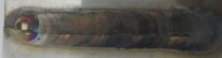 |
Groove defect |
| 9 | 450 | 50 |  |
Groove defect |
| 11.2 | 560 | 50 |  |
Sound joint |
| 14.2 | 710 | 50 |  |
Groove defect |
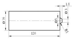
Figure 1 Tungsten carbide tool schematic (dimension in mm)
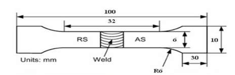
Figure 2 E8M Tensile specimens schematic
| Sample label | (rpm) | v (mm/min) | Tilt angle (deg) | tool offset (mm) | position |
| 1 | 1.5 | On 304L steel | |||
| 2 | 1 | On 304L steel | |||
| 3 | 0.5 | On 304L steel | |||
| 4 | 560 | 50 | 2 | 0 | |
| 5 | 0.5 | On 430 steel | |||
| 6 | 1 | On 430 steel | |||
| 7 | 1.5 | On 430 steel |
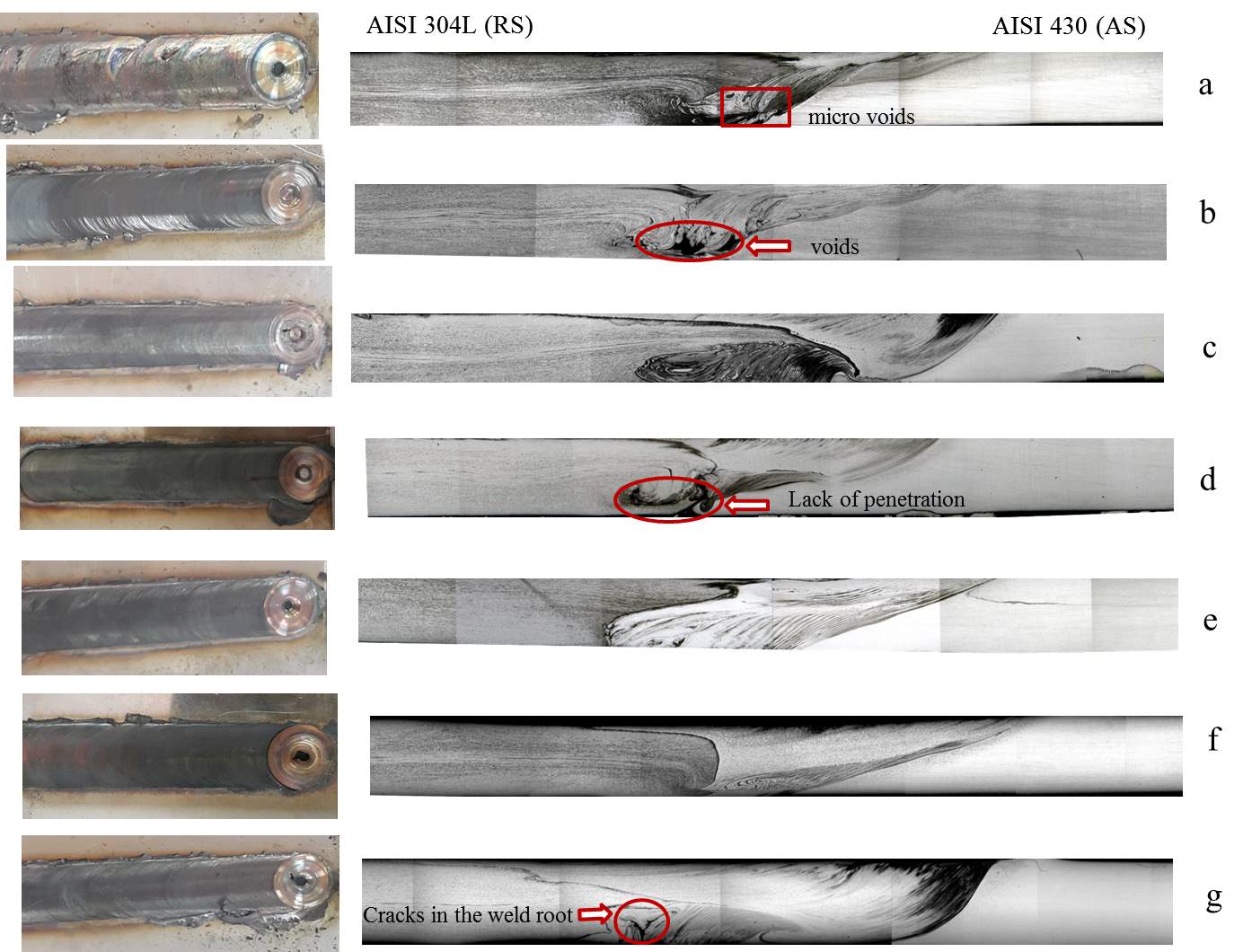
Figure 3 Surface and cross section of the welds after a) 1.5mm b) 1mm c) 0.5mm offset on 304l steel and d) zero state e) 0.5mm f) 1mm g) 1.5mm on 430 steel
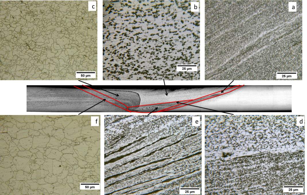
Figure 4 Optical microscopy of cross section of the joint a) thermo-mechanically affected zone-AS b) stir zone- AS (The area affected by shoulder) c) stir zone-RS d) The boundary between the area affected by the shoulder and tool pin e) onion rings f) thermo-mechanically affected zone-RS
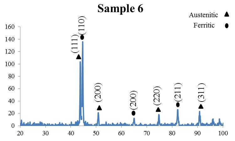
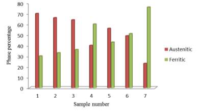
Table 3 Tensile properties of base metals and welding specimens
| sample | UTS (MPa) | Elongation (%) | Fracture place |
| 304L steel BM | 662 | 98 | |
| 430 steel BM | 637 | 41 | |
| 1 | 405 | 6.1 | 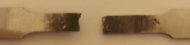 |
| 2 | 349 | 3.74 | 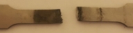 |
| 3 | 472 | 15.53 | 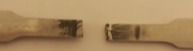 |
| 4 | 172 | 1.19 | 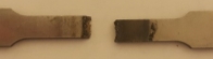 |
| 5 | 450 | 14.98 | 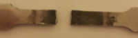 |
| 6 | 470 | 30.2 | 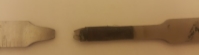 |
| 7 | 340 | 2.16 | 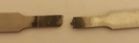 |
Cite This Work
To export a reference to this article please select a referencing stye below:
Related Services
View all


Related Content
All TagsContent relating to: "Physics"
Physics is the area of science that focuses on various aspects of nature, energy, and other areas of natural science. The main purpose of physics is to use experiments and analysis to develop a greater understanding of the universe's behaviour.
Related Articles

DMCA / Removal Request
If you are the original writer of this dissertation and no longer wish to have your work published on the UKDiss.com website then please: