Electronic Health Record (EHR) Development
Info: 13634 words (55 pages) Dissertation
Published: 10th Dec 2019
Tagged: Information Systems
1. INTRODUCTION
1.1 Purpose of the system:
Electronic Health Record (EHR) is longitudinal collection of electronic health information for and about persons, where health information is defined as information pertaining to the health of an individual or health care provided to an individual and it can support of efficient processes for health care delivery. In order to ensure successful an operation of EHR, a Health Information Exchange (HIE) system need to be implemented. However, most of the HIS in service have different characteristics and are mutually incompatible. Hence, effective health information exchange needs to be standardized for interoperable health information exchange between hospitals. Especially, clinical document standardization lies at the core of guaranteeing interoperability. Health Level Seven hased CDA as a major standard for clinical documents. CDA is a document markup standard that specifies the structure and semantics of ‘clinical documents’ for the purpose of exchange. The first version of CDA was developed in 2001 and Release 2 came out in 2005 . Many projects adopting CDA have been successfully completed in many countries. Active works are being done on improving semantic interoperability based on open EHR and CEN13606 . To establish confidence in speed ability, a lot of HIS’s got to support CDA. However, the structure of CDA is extremely complicated and also the production of correct CDA document is tough to realize while not deep understanding of the CDA commonplace and comfortable expertise with it. additionally, the HIS development platforms for hospitals vary thus greatly that generation of CDA documents in every hospital invariably needs a separate CDA generation system. Also, hospitals are terribly reluctant to adopt a brand new system unless it’s completely necessary for provision of care. As a result, the adoption rate of EHR is extremely low aside from in an exceedingly few handful countries like New Zealand or Australia . In the USA, the government implemented an incentive program called the Meaningful Use Program to promote EHR adoption among hospitals [13]. When a patient is diagnosed at a clinic, a CDA document recording the diagnosis is generated. The CDA document can be shared with other clinics if the patient agrees. The concept of family doctor does not exist in Korea, hence it is common for a patient to visit a number of different clinics. The exchange of CDA document is triggered in the following cases: when a physician needs to study a patient’s medical history; when referral and reply letters are drafted for a patient cared by multiple clinics; when a patient is in emergency and the medical history needs to be reviewed. It takes increasing quantity of your time for the medical personnel because the quantity of changed CDA document will increase as a result of additional documents means information ar distributed in numerous documents. This considerably delays the medical personnel in creating selections. Hence, once all of the CDA documents are integrated into one document, the medical personnel is sceptred to review the patient’s clinical history handily in written account order per clinical section and also the follow-up care service is delivered additional effectively. sadly for currently, an answer that integrates multiple CDA documents into one doesn’t exist however to the simplest of our data and there’s a sensible limitation for individual hospitals to develop and implement a CDA document integration technology. during this paper we tend to gift (1) a CDA document generation system that generates CDA documents on completely different developing platforms and (2) a CDA document integration system that integrates multiple CDA documents scattered in numerous hospitals for every patient. the advantages of adopting this system are as follows. First, the system is accessible through an Open API and developers can continue working on their developer platforms they specialize in such as Java, .NET, or C/Cþþ. Hospital systems will merely extend their existing system instead of utterly commutation it with a replacement system. Second, it becomes redundant for hospitals to coach their personnel to get, integrate, and look at standard-compliant CDA documents. The cloud CDA generation service produces documents within the CDA format approved by the National Institute of Standards and Technology (NIST). Third, if this service is provided for complimentary at low worth to hospitals, existing EHR square measure additional possible to contemplate adoption of CDA in their practices. This paper is organized as follows. In Section 2, detailed explanations are given on the format of CDA document, cloud computing, and the overall architecture of our proposed system. Section 3 describes the efficacy of the proposed system and contrasts it to different HIE systems in various countries to highlight the strength of our system.
1.2 Existing System:
Effective health data exchange must be standardized for practical health data exchange between hospitals. Especially, clinical document standardization lies at the core of guaranteeing ability.
It takes increasing quantity of your time for the medical personnel because the quantity of changed CDA document will increase as a result of a lot of documents implies that knowledge ar distributed in numerous documents. This considerably delays the medical personnel in creating selections. Hence, once all of the CDA documents are integrated into one document, the medical personnel is sceptered to review the patients clinical history handily in written account order per clinical section and also the follow-up care service is delivered a lot of effectively. sadly for currently, an answer that integrates multiple CDA documents into one doesn’t exist nevertheless to the simplest of our information and there’s a sensible limitation for individual hospitals to develop and implement a CDA document integration technology.
Disadvantages:
- The HIS development platforms for hospitals vary thus greatly that generation of CDA documents in every hospital invariably needs a separate CDA generation system. Also, hospitals area unit terribly reluctant to adopt a brand new system unless it’s completely necessary for provision of care. As a result, the adoption rate of EHR is extremely low aside from in a very few handful countries.
- Unfortunately for currently, an answer that integrates multiple CDA documents into one doesn’t exist nevertheless to the most effective of our information and there’s a sensible limitation for individual hospitals to develop and implement a CDA document integration technology.
- To establish confidence in belt along ability, a lot of HIS’s ought to support CDA. However, the structure of CDA is extremely complicated and therefore the production of correct CDA document is difficult to attain while not deep understanding of the CDA commonplace and enough expertise with it.
1.3 Proposed System:
In this paper we have a tendency to gift (1) a CDA document generation system that generates CDA documents on totally different developing platforms and (2) a CDA document integration system that integrates multiple CDA documents scattered in numerous hospitals for every patient.CDA Generation API generates CDA documents on cloud. CDA Generation Interface uses the API provided by the cloud and relays the input file and receives CDA documents generated within the cloud.Template Manager is liable for managing the CDA documents generated within the cloud server. Our system uses CCD document templates. CDA Generator collects patient information from hospitals and generates CDA documents within the guide formats as instructed by the guide Manager.CDA Validator inspects whether or not the generated CDA document complies with the CDA schema customary.
Advantages:
- Hospital systems will merely extend their existing system instead of fully commutation it with a brand new system. Second, it becomes inessential for hospitals to coach their personnel to get, integrate, and consider standard-compliant CDA documents.
- The cloud CDA generation service produces documents within the CDA format approved by the National Institute of Standards and Technology (NIST).
- If this service is provided for gratis at low value to hospitals, existing EHR area unit additional seemingly to think about adoption of CDA in their practices.
- Interoperability between hospitals not solely helps improve patient safety and quality of care however conjointly scale back time and resources spent on formatting conversion.
2. SYSTEM REQUIREMENTS
2.1 H/W System Configuration:-
Processor – Pentium –IV
Speed – 2.4 GHz
RAM – 512 MB(min)
Hard Disk – 20 GB
Floppy Drive – 1.44 MB
Key Board – Standard Windows Keyboard
2.2 S/W System Configuration:-
Operating System : Windows95/98/2000/XP
Application Server : Tomcat5.0/6.X
Front End : HTML, Java, Jsp
Scripts : JavaScript.
Server side Script : Java Server Pages.
Database Connectivity : MySQL.
2.3 MODULES OF THE SYSTEM
- Construction of System Environment
- The CDA Document
- Construction of a Cloud Computing Environment
- Integration of CDA Documents via Our Cloud Server
2.3.1 Construction of System Environment
- In the first module we develop the Construction of the System Environment to prove our proposed system model. In this module we develop Hospital A, Hospital B, Doctor,Patient/User, Admin and Cloud Modules.
- In Hospital A, we create the User Authorization with Login Credentials. This module provides the option of Upload the Patient details as XML File in the Cloud with Encrypted and also provides the option to check the status of the uploaded file with the XML Format. The same is followed in the Hospital B too.
- In the Admin part, we provide the Admin Authorization with login Credentials and view pending request of users and doctors. The admin only give Approval to the request by sending secret key to user/doctor to access the file.
- In cloud Login, view the patient details in the XML format which is acquired from CDA.
2.3.2 The CDA Document
- In this module we develop the CDA document. The HL7 Clinical Document Architecture Release 2 (CDA R2) was approved by American Nation Standards Institute. It is an XML-based document markup standard that specifies the structure and semantics of clinical documents, and its primary purpose is facilitating clinical document exchanges between heterogeneous software systems.
- A CDA document is divided into its header and body. The header has a clearly defined structure and it includes information about the patient, hospital, physician, etc. The body is more flexible than the header and contains various clinical data.
- Each piece of clinical data is allocated a section and given a code as defined in the Logical Observation Identifiers Names and Codes (LOINC). Different subcategories are inserted in a CDA document depending on the purpose of the document, and we chose the Continuity of Care Document (CCD) because it contains the health summary data for the patient and it is also widely used for interoperability.
2.3.3 Construction of a Cloud Computing Environment
- In this module we develop the Cloud computing environment. We use DriveHQ Cloud Service provider to upload our files in the Cloud.
- In this module, we develop the construction of a Cloud Computing Environment and how multiple CDA documents are integrated into one in our CDA Document Integration System. The standard for this is Korean Standard for CDA Referral and Reply Letters (Preliminary Version). Templates which generate a CDA use CCD part of Consolidated CDA which is released by ONC and made by HL7. However, an actually generated CDA has a form of CDA Referral and Reply Letters.
- The rationale for CDA document integration is as followed. When CDA-based HIE (Health Information Exchange) is actively used among hospitals, the number of CDA documents pertaining to each patient increases in time. Physicians need to spend a significant portion of their time on reading these documents for making clinical decisions.
- At a hospital, the CDA documents to be integrated are processed through our CDA Integration API. The CDA Integration Interface relays each CDA document sent to the cloud to the CDA Parser, which converts each input CDA document to an XML object and analyzes the CDA header and groups them by each patient ID. The CDA Document Integrator integrates the provided multiple CDA documents into a single CDA document. In this process, the data in the same section in the document body are merged.
2.3.4 Integration of CDA Documents via Our Cloud Server
- We integrated multiple CDA documents of patient referrals and replies by using the API at our server. The use case scenario and patient data used for integration are shown in this module.
- We adopted sample patient data provided by the US EHR Certification Program, Meaningful Use. The data does not pertain to an actual person. It is fictional, and available for public access. This module is to show how a client integrating multiple CDA documents by using our API. The sample many clinical documents are shown to be successfully integrated.
3. SYSTEM STUDY
The feasibleness of the project is analyzed during this section and business proposal is place forth with a really general arrange for the project and a few price estimates. throughout system analysis the feasibleness study of the projected system is to be allotted. this can be to confirm that the projected system isn’t a burden to the corporate. For feasibleness analysis, some understanding of the main necessities for the system is important.
Three key concerns concerned within the feasibleness analysis square measure
- ECONOMICAL FEASIBILITY
- TECHNICAL FEASIBILITY
- SOCIAL FEASIBILITY
3.2 ECONOMICAL FEASIBILITY
This study is allotted to examine the economic impact that the system can wear the organization. the number of fund that the corporate will pour into the analysis and development of the system is proscribed. The expenditures should be even. therefore the developed system similarly at intervals the budget and this was achieved as a result of most of the technologies used square measure freely obtainable. solely the custom merchandise had to be purchased.
3.3 TECHNICAL FEASIBILITY
This study is dispensed to envision the technical practicableness, that is, the technical necessities of the system. Any system developed should not have a high demand on the obtainable technical resources. this may cause high demands on the obtainable technical resources. this may cause
high demands being placed on the shopper. The developed system should have a modest demand, as solely lowest or null changes area unit needed for implementing this technique.
3.4 SOCIAL FEASIBILITY
The side of study is to envision the amount of acceptance of the system by the user. This Includes the method of coaching the user to use the system expeditiously. The user should not feel vulnerable by the system, instead should settle for it as a necessity. the amount of acceptance by the users entirely depends on the strategies that square measure utilized to coach the user regarding the system and to form him at home with it. His level of confidence should be raised so he’s conjointly able to build some constructive criticism, that is welcome, as he’s the ultimate user of the system.
3.5 What is cloud computing?
Cloud computing is that the use of computing resources (hardware and software) that square measure delivered as a service over a network (typically the Internet). The name comes from the common use of a cloud-shaped image as AN abstraction for the complicated infrastructure it contains in system diagrams. Cloud computing entrusts remote services with a user’s information, software system and computation. Cloud computing consists of hardware and software system resources created accessible on the web as managed third-party services. These services usually give access to advanced software system applications and high-end networks of server computers.
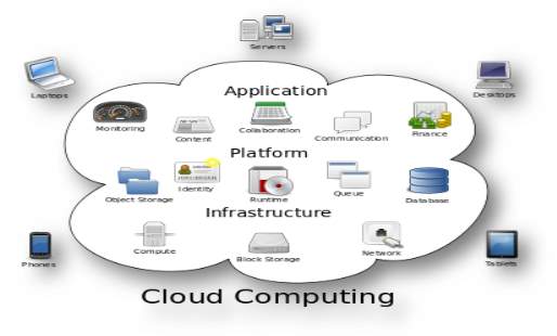
FIG 3.5 Structure of cloud computing
3.6 How Cloud Computing Works?
The goal of cloud computing is to use ancient supercomputing, or superior computing power, commonly employed by military and analysis facilities, to perform tens of trillions of computations per second, in consumer-oriented applications like monetary portfolios, to deliver personalised data, to supply information storage or to power massive, immersive laptop games.
The cloud computing uses networks of enormous teams of servers generally running cheap client computer technology with specialised connections to unfold data-processing chores across them. This shared IT infrastructure contains massive pools of systems that area unit joined along. Often, virtualization techniques area unit accustomed maximize the ability of cloud computing.
3.7 Characteristics and Services Models:
The salient characteristics of cloud computing supported the definitions provided by the National Institute of Standards and nomenclature (NIST) square measure made public below:
• On-demand self-service: A client will unilaterally provision computing capabilities, like server time and network storage, PRN mechanically while not requiring human interaction with every service’s supplier.
• Broad network access: Capabilities square measure obtainable over the network and accessed through customary mechanisms that promote use by heterogeneous skinny or thick consumer platforms (e.g., mobile phones, laptops, and PDAs).
• Resource pooling: The provider’s computing resources square measure pooled to serve multiple shoppers employing a multi-tenant model, with totally different physical and virtual resources dynamically assigned and reassigned consistent with client demand. there’s a way of location-independence in this the client typically has no management or data over the precise location of the provided resources however could also be ready to specify location at the next level of abstraction (e.g., country, state, or knowledge center). samples of resources embody storage, processing, memory, network information measure, and virtual machines.
• Rapid elasticity: Capabilities will be chop-chop and elastically provisioned, in some cases mechanically, to quickly scale out and chop-chop free to quickly scale in. To the patron, the capabilities obtainable for provisioning usually seem to be unlimited and may be purchased in any amount at any time.
• Measured service: Cloud systems mechanically management and optimize resource use by investing a metering capability at some level of abstraction applicable to the sort of service (e.g., storage, processing, bandwidth, and active user accounts). Resource usage will be managed, controlled, and according providing transparency for each the supplier and client of the used service
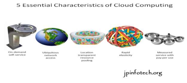
FIG 3.7 Characteristics of cloud computing
3.8 Services Models:
Cloud Computing contains 3 totally different service models, specifically Infrastructure-as-a-Service (IaaS), Platform-as-a-Service (PaaS), and Software-as-a-Service (SaaS). The 3 service models or layer ar completed by associate user layer that encapsulates the top user perspective on cloud services. The model is shown in figure below. If a cloud user accesses services on the infrastructure layer, for example, she will be able to run her own applications on the resources of a cloud infrastructure and stay liable for the support, maintenance, and security of those applications herself. If she accesses a service on the applying layer, these tasks ar usually taken care of by the cloud service supplier.
.
FIG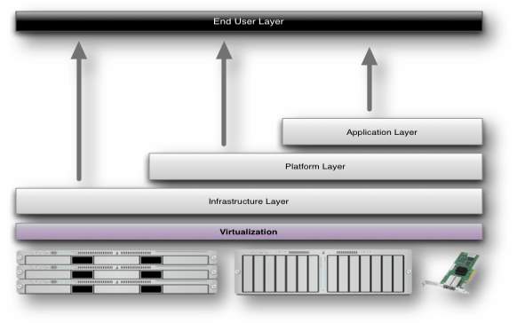
FIG 3.8 Structure of service models
3.9 Benefits of cloud computing:
. win economies of scale – increase volume output or productivity with fewer individuals. Your value per unit, project or product plummets.
2. scale back payment on technology infrastructure. Maintain easy accessibility to your info with smallest direct payment. Pay as you go (weekly, quarterly or yearly), supported demand.
3. extend your hands on a budget. individuals worldwide will access the cloud, provided they need an online association.
4. contour processes. Get additional work exhausted less time with less individuals.
5. scale back capital prices. There’s no got to pay big bucks on hardware, package or licensing fees.
6. Improve accessibility. you’ve got access anytime, anywhere, creating your life such a lot easier!
7. Monitor comes additional effectively. keep at intervals budget and prior completion cycle times.
8. Less personnel coaching is required. It takes fewer individuals to try to to additional work on a cloud, with a smallest learning curve on hardware and package problems.
9. Minimize licensing new package. Stretch and grow while not the necessity to shop for valuable package licenses or programs.
10. Improve flexibility. you’ll amendment direction while not serious “people” or “financial” problems at stake.
3.10 Advantages:
1.Price Pay for under the resources used.
2.Security: Cloud instances square measure isolated within the network from alternative instances for improved security.
3.Performance: Instances is intercalary instantly for improved performance. purchasers have access to the whole resources of the Cloud’s core hardware.
4.Scalability: Auto-deploy cloud instances once required.
5.Uptime: Uses multiple servers for optimum redundancies. just in case of server failure, instances is mechanically created on another server.
6.Control: ready to login from any location. Server photograph and a software system library allows you to deploy custom instances.
Traffic: Deals with spike in traffic with fast preparation of extra instances to handle the load.
3.11 SYSTEM ARCHITECTURE:

FIG 3.11 System architecture
3.12 DATA FLOW DIAGRAM:
- 1.The DFD is additionally known as as bubble chart. it’s an easy graphical formalism that may be wont to represent a system in terms of computer file to the system, varied process dole out on this information, and therefore the output information is generated by this technique.
- 2.the info flow chart (DFD) is one in all the foremost vital modeling tools. it’s wont to model the system parts. These parts area unit the system method, the info utilized by the method, Associate in Nursing external entity that interacts with the system and therefore the data flows within the system.
- 3.DFD shows however the data moves through the system and the way it’s changed by a series of transformations. it’s a graphical technique that depicts data flow and therefore the transformations that area unit applied as information moves from input to output.
- 4.DFD is additionally called bubble chart. A DFD could also be wont to represent a system at any level of abstraction. DFD could also be divided into levels that represent increasing data flow and practical detail.
FIG 3.12 Data flow diagram
4. SOFTWARE ENVIRONMENT
4.1 The Java Programming Language
The Java programing language could be a problem-oriented language that may be characterised by all of the subsequent buzzwords:
1. Simple
2. design neutral
3. Object homeward
4. Portable
5. Distributed
6. High performance
7. Interpreted
8. Multithreaded
9. Robust
10. Dynamic
11. Secure
With most programming languages, you either compile or interpret a program so you’ll be able to run it on your laptop. The Java programing language is uncommon therein a program is each compiled and taken. With the compiler, 1st you translate a program into AN intermediate language known as Java computer memory unit codes —the platform-independent codes taken by the interpreter on the Java platform. The interpreter parses and runs every Java computer memory unit code instruction on the pc. Compilation happens simply once; interpretation happens anytime the program is dead. the subsequent figure illustrates however this works.
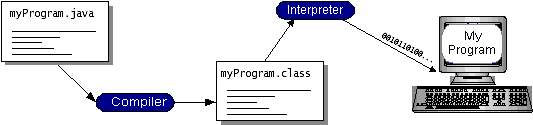
FIG 4.1.1 JAVA WORKING
You can think about Java computer memory unit codes because the computer code directions for the Java Virtual Machine (Java VM). each Java interpreter, whether or not it’s a development tool or an online browser that may run applets, is AN implementation of the Java VM. Java computer memory unit codes facilitate create “write once, run anywhere” doable. you’ll be able to compile your program into computer memory unit codes on any platform that features a Java compiler. The computer memory unit codes will then be run on any implementation of the Java VM. meaning that as long as a laptop features a Java VM, constant program written within the Java programing language will run on Windows 2000, a Solaris digital computer, or on AN iMac.
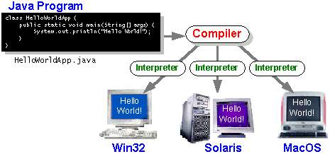
FIG 4.1.2 JAVA ON DIFFERENT OS
4.2 The Java Script
JavaScript (JS) could be a dynamic programing language.[5] it’s most ordinarily used as a part of net browsers, whose implementations permit client-side scripts to act with the user, management the browser, communicate asynchronously, and alter the document content that’s displayed.[5] it’s conjointly getting used in server-side programming, game development and also the creation of desktop and mobile applications.
JavaScript could be a prototype-based scripting language with dynamic typewriting and has fantabulous functions. Its syntax was influenced by C. JavaScript copies several names and naming conventions from Java, however the 2 languages square measure otherwise unrelated and have terribly completely different linguistics. The key style principles at intervals JavaScript square measure taken from the Self and theme programming languages. it’s a multi-paradigm language, supporting object-oriented,[7] imperative, and functional] programming designs.
The application of JavaScript in use outside of net pages—for example, in PDF documents, site-specific browsers, and desktop widgets—is conjointly vital. Newer and quicker JavaScript VMs and platforms engineered upon them (notably Node.js) have conjointly accumulated the recognition of JavaScript for server-side net applications. On the shopper aspect, JavaScript was historically enforced as AN taken language however just-in-time compilation is currently performed by recent (post-2012) browsers.JavaScript was formalized within the ECMAScript language customary and is primarily used as a part of an online browser (client-side JavaScript). this permits programmatic access to machine objects at intervals a bunch setting.
The most common use of JavaScript is to write down functions that square measure embedded in or enclosed from hypertext markup language pages which act with the Document Object Model (DOM) of the page. Some easy samples of this usage are:Loading new page content or submitting knowledge to the server via mythical being while not reloading the page (for example, a social network would possibly permit the user to post standing updates while not deed the page)
Animation of page parts, weakening them in and out, resizing them, moving them, etc.Interactive content, for instance games, and taking part in audio and video
Validating input values of an online kind to create positive that they’re acceptable before being submitted to the server.Transmitting info regarding the user’s reading habits and browsing activities to numerous websites. websites ofttimes do that for net analytics, ad chase, personalization or alternative functions.Because JavaScript code will run regionally during a user’s browser (rather than on a distant server), the browser will reply to user actions quickly, creating AN application additional responsive. moreover, JavaScript code will discover user actions that hypertext markup language alone cannot, like individual keystrokes. Applications like Gmail profit of this: abundant of the user-interface logic is written in JavaScript, ANd JavaScript dispatches requests for info (such because the content of an e-mail message) to the server. the broader trend of mythical being programming equally exploits this strength.
A JavaScript engine (also called JavaScript interpreter or JavaScript implementation) is AN interpreter that interprets JavaScript ASCII text file and executes the script consequently. the primary JavaScript engine was created by Brendan Eich at Netscape Communications Corporation, for the Netscape Navigator browser. The engine, code-named SpiderMonkey, is enforced in C. it’s since been updated (in JavaScript one.5) to adapt to ECMA-262 Edition three. The perissodactyl engine, created primarily by Norris Boyd (formerly of Netscape; currently at Google) could be a JavaScript implementation in Java. Rhino, like SpiderMonkey, is ECMA-262 Edition three compliant.
A web browser is far and away the foremost common host setting for JavaScript. net browsers generally produce “host objects” to represent the Document Object Model (DOM) in JavaScript. the online server is another common host setting. A JavaScript webserver would generally expose host objects representing HTTP request and response objects, that a JavaScript program might then interrogate and manipulate to dynamically generate websites.
Because JavaScript is that the solely language that the foremost common browsers share support for, it’s become a target language for several frameworks in alternative languages, even if JavaScript was ne’er supposed to be such a language.[53] Despite the performance limitations inherent to its dynamic nature, the increasing speed of JavaScript engines has created the language a astonishingly possible compilation target.
4.3 ODBC
Microsoft Open info property (ODBC) could be a customary programming interface for application developers and info systems suppliers. Before ODBC became a factual customary for Windows programs to interface with info systems, programmers had to use proprietary languages for every info they needed to attach to. Now, ODBC has created the selection of the info system virtually extraneous from a committal to writing perspective, that is because it ought to be. Application developers have way more vital things to fret regarding than the syntax that’s required to port their program from one info to a different once business desires suddenly amendment.
Through the ODBC Administrator au fait Panel, you’ll be able to specify the actual info that’s related to an information supply that AN ODBC computer program is written to use. think about AN ODBC knowledge supply as a door with a reputation thereon. every door can lead you to a selected info. for instance, the info supply named Sales Figures may be a SQL Server info, whereas the Accounts owed knowledge supply might talk to AN Access info. The physical info mentioned by an information supply will reside anyplace on the computer network.
The ODBC system files don’t seem to be put in on your system by Windows ninety five. Rather, they’re put in after you setup a separate info application, like SQL Server shopper or Visual Basic four.0. once the ODBC icon is put in au fait Panel, it uses a file known as ODBCINST.DLL. it’s conjointly doable to administer your ODBC knowledge sources through a complete program known as ODBCADM.EXE. there’s a 16-bit and a 32-bit version of this program and every maintains a separate list of ODBC knowledge sources.
From a programming perspective, the sweetness of ODBC is that the applying are often written to use constant set of perform calls to interface with any knowledge supply, despite the info marketer. The ASCII text file of the applying doesn’t amendment whether or not it talks to Oracle or SQL Server. we tend to solely mention these 2 as AN example. There square measure ODBC drivers out there for many dozen common info systems. Even stand out spreadsheets and plain text files are often changed into knowledge sources. The software package uses the written account info written by ODBC Administrator to see that low-level ODBC drivers square measure required to speak to the info supply (such because the interface to Oracle or SQL Server). The loading of the ODBC drivers is clear to the ODBC computer program. during a client/server setting, the ODBC API even handles several of the network problems for the applying technologist.
The advantages of this theme square measure therefore varied that you simply square measure most likely thinking there should be some catch. the sole disadvantage of ODBC is that it isn’t as economical as talking on to the native info interface. ODBC has had several detractors create the charge that it’s too slow. Microsoft has continuously claimed that the crucial consider performance is that the quality of the motive force code that’s used. In our humble opinion, this can be true. the supply of fine ODBC drivers has improved a good deal recently. And anyway, the criticism regarding performance is somewhat analogous to those that same that compilers would ne’er match the speed of pure programing language. Maybe not, however the compiler (or ODBC) offers you the chance to write down cleaner programs, which implies you end sooner. Meanwhile, computers get quicker each year.
4.4 JDBC
In an endeavor to line AN freelance info customary API for Java; Sun Microsystems developed Java info property, or JDBC. JDBC offers a generic SQL info access mechanism that has an even interface to a range of RDBMSs. This consistent interface is achieved through the employment of “plug-in” info property modules, or drivers. If a info marketer needs to possess JDBC support, he or she should offer the motive force for every platform that the info and Java run on.
To gain a wider acceptance of JDBC, Sun primarily based JDBC’s framework on ODBC. As you discovered earlier during this chapter, ODBC has widespread support on a range of platforms. Basing JDBC on ODBC can permit vendors to bring JDBC drivers to promote abundant quicker than developing a very new property resolution.
JDBC was proclaimed in March of 1996. it had been discharged for a ninety day public review that concluded Gregorian calendar month eight, 1996. due to user input, the ultimate JDBC v1.0 specification was discharged presently when.
The remainder of this section can cowl enough info regarding JDBC for you to understand what it’s regarding and the way to use it effectively. this can be by no suggests that a whole summary of JDBC. that will fill a complete book.
4.5 JDBC Goals
Few code packages square measure designed while not goals in mind. JDBC is one that, due to its several goals, drove the event of the API. These goals, in conjunction with early reviewer feedback, have finalized the JDBC category library into a solid framework for building info applications in Java.
The goals that were set for JDBC square measure vital. they’ll offer you some insight on why bound categories and functionalities behave the approach they are doing. The eight style goals for JDBC square measure as follows:
1.SQL Level API
The designers felt that their main goal was to outline a SQL interface for Java. though not all-time low info interface level doable, it’s at a coffee enough level for higher-level tools and genus Apis to be created. Conversely, it’s at a high enough level for application programmers to use it with confidence. Attaining this goal permits for future tool vendors to “generate” JDBC code and to cover several of JDBC’s complexities from the top user.
2.SQL conformity
SQL syntax varies as you progress from info marketer to info marketer. In an endeavor to support a good form of vendors, JDBC can permit any question statement to be well-versed it to the underlying info driver. this permits the property module to handle non-standard practicality during a manner that’s appropriate for its users.
3.JDBC should be helpful on high of common info interfaces
The JDBC SQL API should “sit” on high of alternative common SQL level genus Apis. This goal permits JDBC to use existing ODBC level drivers by the employment of a code interface. This interface would translate JDBC calls to ODBC and the other way around.
4.Offer a Java interface that’s in keeping with the remainder of the Java system
Because of Java’s acceptance within the user community to this point, the styleers feel that they must not stray from this design of the core Java system.
5.Keep it easy
This goal most likely seems all told code style goal listings. JDBC isn’t any exception. Sun felt that the look of JDBC ought to be terribly easy, granting only 1 technique of finishing a task per mechanism. permitting duplicate practicality solely serves to confuse the users of the API.
6.Use strong, static typewriting where doable
sturdy typewriting permits for additional error checking to be done at compile time; conjointly, less error seem at runtime.
7.Keep the common cases easy
as a result of additional typically than not, the standard SQL calls utilized by the technologist square measure easy SELECT’s, INSERT’s, DELETE’s and UPDATE’s, these queries ought to be easy to perform with JDBC. However, additional advanced SQL statements ought to even be doable.
Finally we tend to set to proceed the implementation mistreatment Java Networking..And for dynamically change the cache table we tend to choose MS Access info. Java has 2 things: a programing language and a platform. Java could be a high-level programing language that’s all of the subsequent
Simple Architecture-neutral
Object-oriented moveable
Distributed superior
Interpreted multithreaded
Robust Dynamic
Java is additionally uncommon therein every Java program is each compiled and taken. With a compile you translate a Java program into AN intermediate language known as Java computer memory unit codes the platform-independent code instruction is passed and run on the pc.
Compilation happens simply once; interpretation happens anytime the program is dead. The figure illustrates however this works.
You can think about Java computer memory unit codes because the computer code directions for the Java Virtual Machine (Java VM). each Java interpreter, whether or not it’s a Java development tool or an online browser that may run Java applets, is AN implementation of the Java VM. The Java VM may also be enforced in hardware.
Java computer memory unit codes facilitate create “write once, run anywhere” doable. you’ll be able to compile your Java program into computer memory unit codes on my platform that features a Java compiler. The computer memory unit codes will then be run any implementation of the Java VM. for instance, constant Java program will run Windows NT, Solaris, and Macintosh.
4.6 Tomcat 6.0 net server
Tomcat is AN open supply net server developed by Apache cluster. Apache house cat is that the servlet instrumentality that’s employed in the official Reference Implementation for the Java Servlet and JavaServer Pages technologies. The Java Servlet and JavaServer Pages specifications square measure developed by Sun beneath the Java Community method. net Servers like Apache house cat support solely net parts whereas AN application server supports net parts furthermore as business parts (BEAs Weblogic, is one among the favored application server).To develop {a net|an internet|an online} application with jsp/servlet install any web server like JRun, house cat etc to run your application.
The figure illustrates how this works.
You can think of Java byte codes as the machine code instructions for the Java Virtual Machine (Java VM). Every Java interpreter, whether it’s a Java development tool or a Web browser that can run Java applets, is an implementation of the Java VM. The Java VM can also be implemented in hardware.
Java byte codes help make “write once, run anywhere” possible. You can compile your Java program into byte codes on my platform that has a Java compiler. The byte codes can then be run any implementation of the Java VM. For example, the same Java program can run Windows NT, Solaris, and Macintosh.
4.6 Tomcat 6.0 web server
Tomcat is an open source web server developed by Apache Group. Apache Tomcat is the servlet container that is used in the official Reference Implementation for the Java Servlet and JavaServer Pages technologies. The Java Servlet and JavaServer Pages specifications are developed by Sun under the Java Community Process. Web Servers like Apache Tomcat support only web components while an application server supports web components as well as business components (BEAs Weblogic, is one of the popular application server).To develop a web application with jsp/servlet install any web server like JRun, Tomcat etc to run your application.
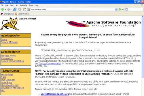
FIG 4.6.1 TOMCAT SERVER PAGE
5. SYSTEM DESIGN
5.1 SYSTEM ARCHITECTURE
Architecture Flow:
Below architecture diagram represents mainly flow of request from the users to database through servers. In this scenario overall system is designed in three tiers separately using three layers called presentation layer, business layer, data link layer. This project was developed using 3-tier architecture.
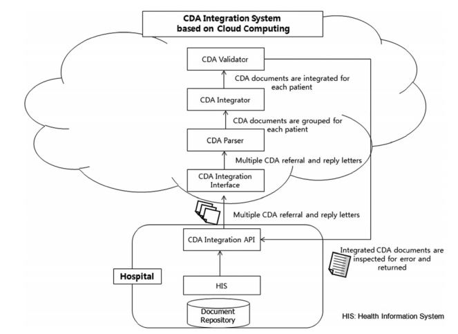
FIG 5.1 3-Tier Architecture
The three-tier software architecture (a three layer architecture) emerged in the 1990s to overcome the limitations of the two-tier architecture. The third tier (middle tier server) is between the user interface (client) and the data management (server) components. This middle tier provides process management where business logic and rules are executed and can accommodate hundreds of users (as compared to only 100 users with the two tier architecture) by providing functions such as queuing, application execution, and database staging.
The three tier architecture is used when an effective distributed client/server design is needed that provides (when compared to the two tier) increased performance, flexibility, maintainability, reusability, and scalability, while hiding the complexity of distributed processing from the user. These characteristics have made three layer architectures a popular choice for Internet applications and net-centric information systems
Advantages of Three-Tier:
- Separates functionality from presentation.
- Clear separation – better understanding.
- Changes limited to well define components.
- Can be running on WWW.
Effective network performance
5.2 UML Concepts
The Unified Modelling Language (UML) may be a normal language for writing code blue prints. The UML may be a language for
Visualizing
Specifying
Constructing
Documenting the artefacts of a code intensive system.
The UML may be a language that provides vocabulary and also the rules for combining words therein vocabulary for the aim of communication. A modelling language may be a language whose vocabulary and also the rules concentrate on the concesptual and physical illustration of a system. Modelling yields associate degree understanding of a system.
5.3 Building Blocks of the UML
The vocabulary of the UML encompasses 3 varieties of building blocks:
Things
Relationships
Diagrams
Things ar the abstractions that ar superior voters in an exceedingly model; relationships tie these items together; diagrams cluster fascinating collections of things.
5.3.1 Things in the UML
There are four varieties of things within the UML:
Structural things
Behavioral things
Grouping things
Annotational things
Structural things ar the nouns of UML models. The structural things employed in the project style are:
First, a category may be a description of a group of objects that share constant attributes, operations, relationships and linguistics.
| Window |
| Origin
Size |
| open()
close() move() display() |
Fig: Classes
Second, a use case is a description of set of sequence of actions that a system performs that yields an observable result of value to particular actor.
Fig: Use Cases
Third, a node is a physical element that exists at runtime and represents a computational resource, generally having at least some memory and often processing capability.
Fig: Nodes
Behavioral things are the dynamic parts of UML models. The behavioral thing used is:
Interaction:
An interaction is a behaviour that comprises a set of messages exchanged among a set of objects within a particular context to accomplish a specific purpose. An interaction involves a number of other elements, including messages, action sequences (the behaviour invoked by a message, and links (the connection between objects).
Fig: Messages
5.3.2 Relationships in the UML:
There ar four varieties of relationships within the UML:
Dependency
Association
Generalization
Realization
A dependency may be a linguistics relationship between 2 factors within which a modification to at least one factor could have an effect on the linguistics of the opposite thing (the dependent thing).
Fig: Dependencies
An association may be a structural relationship that describes a group links, a link being a association among objects. Aggregation may be a special quite association, representing a structural relationship between an entire and its elements.
Fig: Association
A generalization may be a specialization/ generalization relationship within which objects of the specialised component (the child) ar substitutable for objects of the generalized component (the parent)
.
Fig: Generalization
A realization may be a linguistics relationship between classifiers, wherever in one classifier specifies a contract that another classifier guarantees to hold out.
Fig: Realization
5.4 UML DIAGRAMS:
5.4.1 USE CASE Diagram
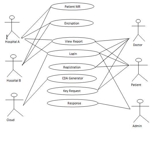
FIG 5.4.1 USE CASE DIAGRAM
The above diagram is Use Case diagram of our system. It shows the set of actions performed by various users. In our system we have 3 types of users. They are 1) Administrator 2) Registered User and 3) Unregistered User. As described earlier, the content in the Ovals are actions performed in the system and those actors are like symbols represent users in system. Those dashed lines from user to action means users are performing those actions respectively.
5.4.2 SEQUENCE Diagram
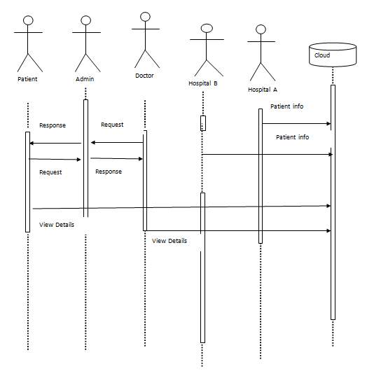
FIG 5.4.2 SEQUENCE DIAGRAM UNREGISTERED USER
The above diagram Show sequence diagram for an unregistered user. It represents sequence or flow of messages in system among various objects of the system in unregistered user’s life time. The rectangle boxes at top represent objects that are invoked by unregistered user and the dashed lines dropping from those boxes are life lines which shows existence of the object up to what time. The boxes on the dashed lines are events and the lines connecting them represent messages and their flow.
5.4.3 CLASS DIAGRAM
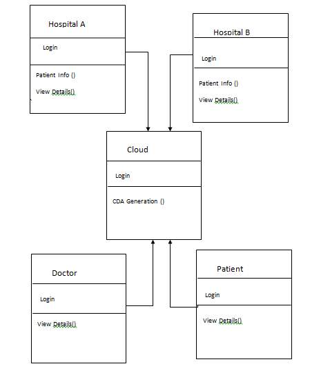
FIG 5.4.3 CLASS DIAGRAM
The above diagram represents class diagram of our system i.e., it shows various classes used in our system and the relationship with one class to other in the system. Each rectangle box represents a class and the upper portion of it represents class name and middle portion represents attributes of the class and the lower represents the functions performed by that class.
5.4.4 ACTIVITY DIAGRAM
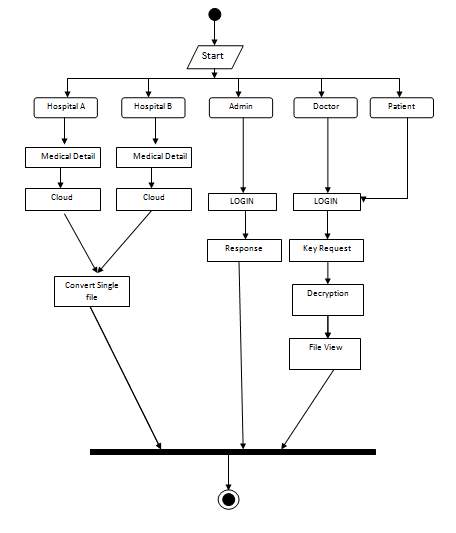
FIG 5.4.4 ACTIVITY DIAGRAM
The above diagram represents activity diagram of the system i.e., it represents the flow of activities in our project Organized User Search Histories. Dot at the start represents starting and dot with circle represents ending and an activity is represented as curve sided rectangle. On seeing it we can understand the flow activities that has to be gone from start to end.
6 CODING AND TESTING
6.1 CODING
6.1.1 ADMIN HOME.JSP
<!doctype html>
<html>
<head>
<script loading="lazy" src=”js/index.js”></script>
<meta http-equiv=”Content-Type” content=”text/html; charset=utf-8″ />
<title>CDA Generation and Integration</title>
<link rel=”stylesheet” href=”css/reset.css” type=”text/css” />
<link rel=”stylesheet” href=”css/styles.css” type=”text/css” />
<link rel=”stylesheet” href=”css/main.css” type=”text/css” />
<script type=”text/javascript” loading="lazy" src=”js/jquery.js”></script>
<script type=”text/javascript” loading="lazy" src=”js/slider.js”></script>
<script type=”text/javascript” loading="lazy" src=”js/superfish.js”></script>
<script type=”text/javascript” loading="lazy" src=”js/custom.js”></script>
<meta name=”viewport” content=”width=device-width, minimum-scale=1.0, maximum-scale=1.0″ />
</head>
<body>
<%
if (request.getParameter(“msg”) != null) {
%>
<script>alert(‘Login Succesfully’);</script>
<%
}
%>
<div id=”container” class=”width”>
<header>
<div class=”width”><br>
<h3><font style=”color: white”>CDA Generation and Integration for Health Information <br> Exchange Based on Cloud Computing System</font></h3>
<nav>
<%—menu start —%>
<ul class=”sf-menu dropdown”>
<li class=”selected”><a href=”admin_home.jsp”>Cloud Home</a></li>
<li><a href=”d_u_details.jsp”>Doctor and User details</a></li>
<li><a href=”doc_req.jsp”>Doctor Request</a></li>
<li><a href=”user_req.jsp”>Patient Request</a></li>
<li><a href=”index.jsp”>logout</a></li>
</ul>
<%—menu end —%>
<div class=”clear”></div>
</nav>
</div>
<div class=”clear”></div>
</header>
<div id=”intro”>
<div class=”width”>
<div class=”intro-content”>
<img loading="lazy" src=”img/ad.jpg” style=”height: 400px; width: 920px” alt=””>
<%—– Start body—–%>
<%—– Start body—–%>
</div>
</div>
</div>
<div id=”body” class=”width”>
<section id=”content” class=”two-column with-right-sidebar”>
</section>
<div class=”clear”></div>
</div>
<footer class=”width”>
<div class=”footer-bottom”>
<p>© </p>
</div>
</footer>
</div>
</body>
</html>
6.1.2 CLOUD HOME
<!doctype html>
<html>
<head>
<script loading="lazy" src=”js/index.js”></script>
<meta http-equiv=”Content-Type” content=”text/html; charset=utf-8″ />
<title>CDA Generation and Integration</title>
<link rel=”stylesheet” href=”css/reset.css” type=”text/css” />
<link rel=”stylesheet” href=”css/styles.css” type=”text/css” />
<link rel=”stylesheet” href=”css/main.css” type=”text/css” />
<script type=”text/javascript” loading="lazy" src=”js/jquery.js”></script>
<script type=”text/javascript” loading="lazy" src=”js/slider.js”></script>
<script type=”text/javascript” loading="lazy" src=”js/superfish.js”></script>
<script type=”text/javascript” loading="lazy" src=”js/custom.js”></script>
<meta name=”viewport” content=”width=device-width, minimum-scale=1.0, maximum-scale=1.0″ />
</head>
<body>
<%
if (request.getParameter(“msg”) != null) {
%>
<script>alert(‘Login Succesfully’);</script>
<%
}
%>
<div id=”container” class=”width”>
<header>
<div class=”width”><br>
<h3><font style=”color: white”>CDA Generation and Integration for Health Information <br> Exchange Based on Cloud Computing System</font></h3>
<nav>
<%—menu start —%>
<ul class=”sf-menu dropdown”>
<li class=”selected”><a href=”cloud_home.jsp”>Cloud Home</a></li>
<li><a href=”cda_gene.jsp”>CDA Generated</a></li>
<li><a href=”index.jsp”>logout</a></li>
</ul>
<%—menu end —%>
<div class=”clear”></div>
</nav>
</div>
<div class=”clear”></div>
</header>
<div id=”intro”>
<div class=”width”>
<div class=”intro-content”>
<img loading="lazy" src=”img/hosh.jpg” style=”height: 400px; width: 920px” alt=””>
<%—– Start body—–%>
<%—– Start body—–%>
</div>
</div>
</div>
<div id=”body” class=”width”>
<section id=”content” class=”two-column with-right-sidebar”>
</section>
<div class=”clear”></div>
</div>
<footer class=”width”>
<div class=”footer-bottom”>
<p>© </p>
</div>
</footer>
</div>
</body>
</html>
6.1.3 INDEX.HTML
<!doctype html>
<html>
<head>
<link rel=”stylesheet” href=”css/lo1.css”>
<link rel=”stylesheet” href=”css/lo2.css”>
<script loading="lazy" src=”js/index.js”></script>
<link rel=”stylesheet” href=”css/style1.css”>
<meta http-equiv=”Content-Type” content=”text/html; charset=utf-8″ />
<title>CDA Generation and Integration</title>
<link rel=”stylesheet” href=”css/reset.css” type=”text/css” />
<link rel=”stylesheet” href=”css/styles.css” type=”text/css” />
<link rel=”stylesheet” href=”css/main.css” type=”text/css” />
<script type=”text/javascript” loading="lazy" src=”js/jquery.js”></script>
<script type=”text/javascript” loading="lazy" src=”js/slider.js”></script>
<script type=”text/javascript” loading="lazy" src=”js/superfish.js”></script>
<script type=”text/javascript” loading="lazy" src=”js/custom.js”></script>
<meta name=”viewport” content=”width=device-width, minimum-scale=1.0, maximum-scale=1.0″ />
</head>
<body>
<div id=”container” class=”width”>
<header>
<div class=”width”><br>
<h3><font style=”color: white”>CDA Generation and Integration for Health Information <br> Exchange Based on Cloud Computing System</font></h3>
<nav>
<%—menu start —%>
<ul class=”sf-menu dropdown”>
<li class=”selected”><a href=”index.jsp”> Home</a></li>
<li>
<a href=”hos_a.jsp”>Hospital A</a>
</li>
<li>
<a href=”hos_b.jsp”>Hospital B</a>
</li>
<li>
<a href=”doc.jsp”> Physician </a>
<ul>
<li><a href=”doc_reg.jsp”>Register</a></li>
<li><a href=”doc_login.jsp”>Login</a></li>
</ul>
</li>
<li>
<a href=”user.jsp”> User Session </a>
<ul>
<li><a href=”user_reg.jsp”>Register</a></li>
<li><a href=”user_login.jsp”>Login</a></li>
</ul>
</li>
<li><a href=”cloud.jsp”>Cloud</a></li>
<li><a href=”Admin.jsp”>Admin</a></li>
</ul>
<%—menu end —%>
<div class=”clear”></div>
</nav>
</div>
<div class=”clear”></div>
</header>
<div id=”intro”>
<div class=”width”>
<div class=”intro-content”>
<img loading="lazy" src=”img/index.JPG” style=”height: 400px; width: 920px” alt=””>
</div>
</div>
</div>
<div id=”body” class=”width”>
<section id=”content” class=”two-column with-right-sidebar”>
</section>
<div class=”clear”></div>
</div>
<footer class=”width”>
<div class=”footer-bottom”>
<p>© </p>
</div>
</footer>
</div>
</body>
</html>
6.1.4 DB CONNECTION
package Dbcon;
import java.sql.Connection;
import java.sql.DriverManager
public class DbConnection {
public static Connection getConnection()
{
Connection con = null;
try{
Class.forName(“com.mysql.jdbc.Driver”);
con = DriverManager.getConnection(“jdbc:mysql://localhost:3306/health_information”, “root”, “root”);
}
catch(Exception e)
{
e.printStackTrace();
}
return con;
}
}
6.2 SYSTEM TESTING
The purpose of testing is to get errors. Testing is that the method of attempting to get each conceivable fault or weakness in an exceedingly work product. It provides some way to examine the practicality of parts, sub-assemblies, assemblies associate degreed/or a finished product it’s the method of exertion software system with the intent of guaranteeing that the software package meets its needs and user expectations and doesn’t fail in an unacceptable manner. There area unit numerous forms of check. every check sort addresses a particular testing demand.
6.2.1 Types of TESTS
1. Unit testing
Unit checking involves the planning of test cases that validate that the interior program logic is functioning properly, which program inputs turn out valid outputs. All call branches and internal code flow ought to be valid. it’s the testing of individual software system units of the applying .it is done once the completion of a personal unit before integration. this can be a structural testing, that depends on data of its construction and is invasive. Unit checks perform basic tests at part level and test a particular business method, application, and/or system configuration. Unit tests make sure that every distinctive path of a business method performs accurately to the documented specifications and contains clearly outlined inputs and expected results.
2. Integration testing
Integration tests area unit designed to check integrated software system parts to work out if they really run jointly program. Testing is event driven and is additional involved with the essential outcome of screens or fields. Integration tests demonstrate that though the parts were one by one satisfaction, as shown by with success unit testing, the mix of parts is correct and consistent. Integration testing is specifically geared toward exposing the issues that arise from the mix of parts.
3. purposeful check
Functional tests give systematic demonstrations that functions tested area unit accessible as such by the business and technical needs, system documentation, and user manuals.
Functional testing is focused on the subsequent items:
- Valid Input : known categories of valid input should be accepted.
- Invalid Input : known categories of invalid input should be rejected.
- Functions : known functions should be exercised.
- Output : known categories of application outputs should be exercised.
- Systems/Procedures: interfacing systems or procedures should be invoked.
Organization and preparation of purposeful tests is concentrated on needs, key functions, or special check cases. additionally, systematic coverage relating determine Business method flows; knowledge fields, predefined processes, and consecutive processes should be thought-about for testing. Before purposeful testing is complete, extra tests area unit known and also the effective price of current tests is set.
4. System check
System testing ensures that the complete integrated software package meets needs. It tests a configuration to confirm far-famed and sure results. associate degree example of system checking is that the configuration oriented system integration test. System testing is predicated on method descriptions and flows, accenting pre-driven method links and integration points.
5. White Box Testing
White Box Testing may be a testing during which during which the software system tester has data of the inner workings, structure and language of the software system, or a minimum of its purpose. it’s purpose. it’s accustomed check areas that can’t be reached from a recording equipment level.
6. recording equipment Testing
Black Box Testing is testing the software system with none data of the inner workings, structure or language of the module being tested. recording equipment tests, as most other forms of tests, should be written from a definitive supply document, like specification or needs document, like specification or needs document. it’s a checking during which the software system below test is treated, as a recording equipment .you cannot “see” into it. The check provides inputs and responds to outputs while not considering however the software system works.
6.2.2 Unit Testing:
Unit checking is typically conducted as a part of a combined code and unit test part of the software system lifecycle, though it’s not uncommon for committal to writing and unit testing to be conducted as 2 distinct phases.
Test strategy and approach
Field testing are performed manually and purposeful tests are written well.
Test objectives
• All field entries should work properly.
• Pages should be activated from the known link.
• The entry screen, messages and responses should not be delayed.
Features to be tested
• Verify that the entries area unit of the right format
• No duplicate entries ought to be allowed
• All links ought to take the user to the right page.
6.2.3 Integration Testing
Software integration testing is that the progressive integration testing of 2 or additional integrated software system parts on one platform to supply failures caused by interface defects. The task of the mixing check is to examine that parts or software system applications, e.g. parts in an exceedingly software package or – one intensify – software system applications at the corporate level – move while not error.
Test Results: All the check cases mentioned higher than passed with success. No defects encountered.
6.2.4 Acceptance Testing
User Acceptance Testing may be a crucial part of any project and needs important participation by the tip user. It conjointly ensures that the system meets the purposeful needs.
Test Results: All the check cases mentioned higher than passed with success. No defects encountered.
8. OUTPUT SCREENS
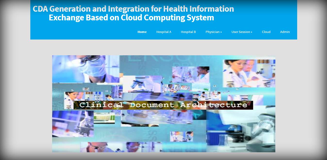
FIG 8.1 home page of the CDA
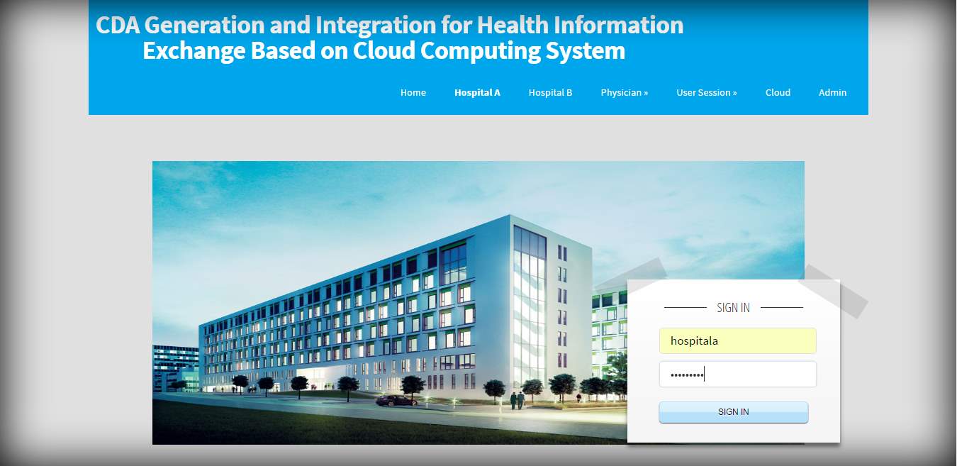
FIG 8.2 Login page of hospital A
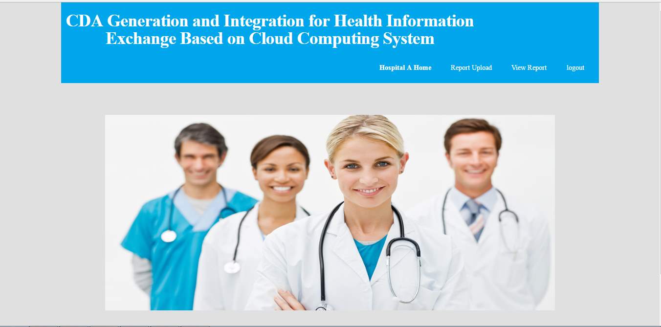 FIG 8.3 Hospital A home page
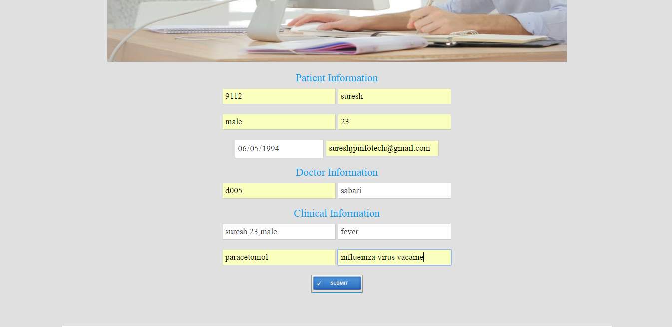
FIG 8.4 Patient information of record upload
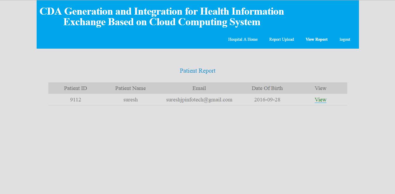
FIG 8.5 Patient report
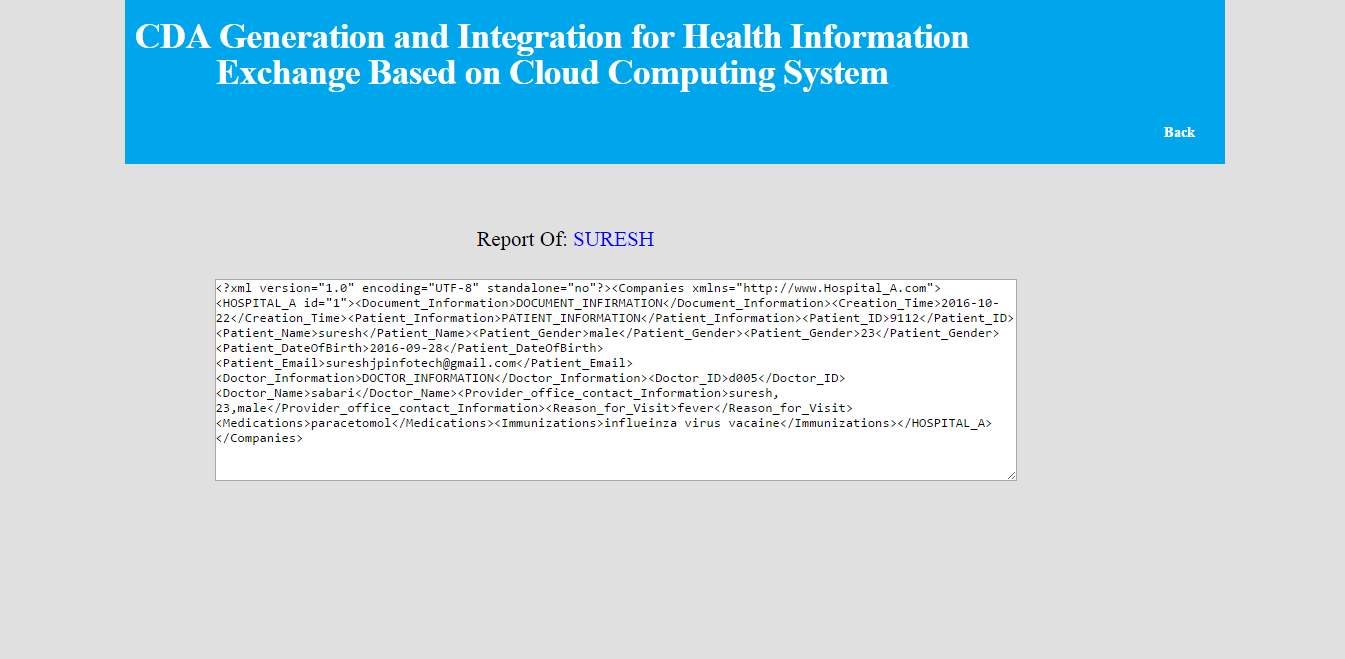
FIG 8.6 patient report information view.
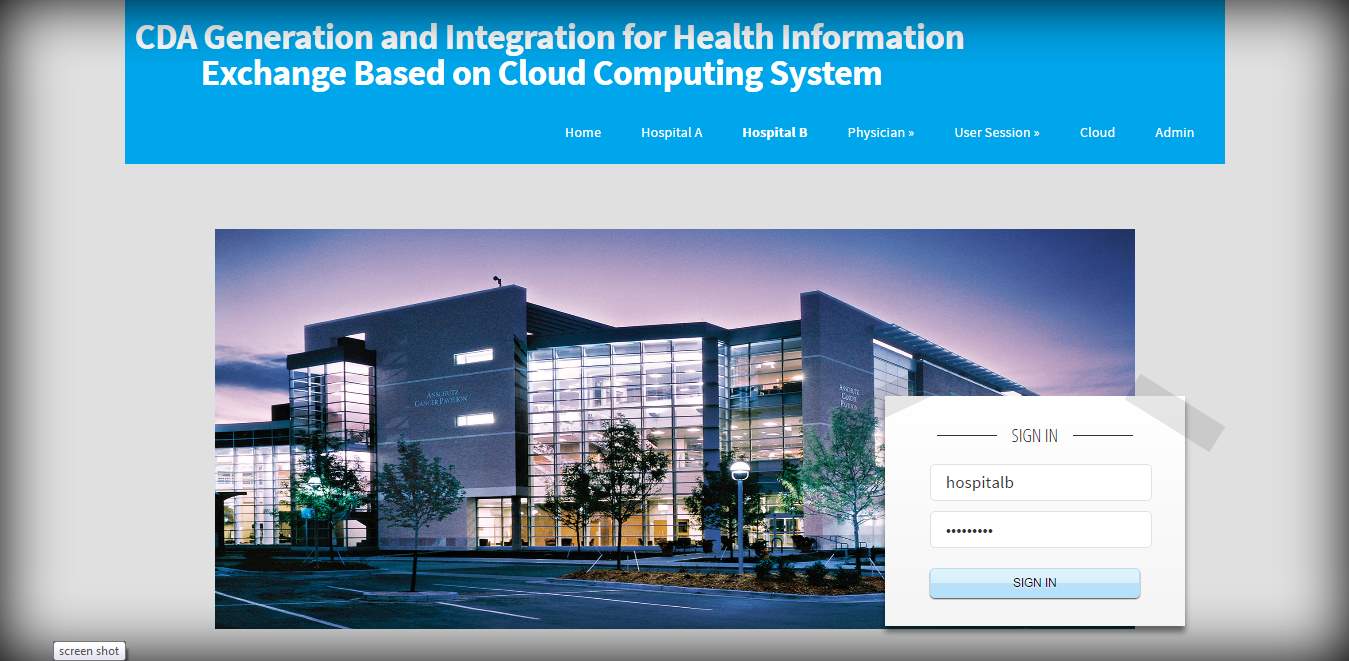
FIG 8.7 Hospital B login
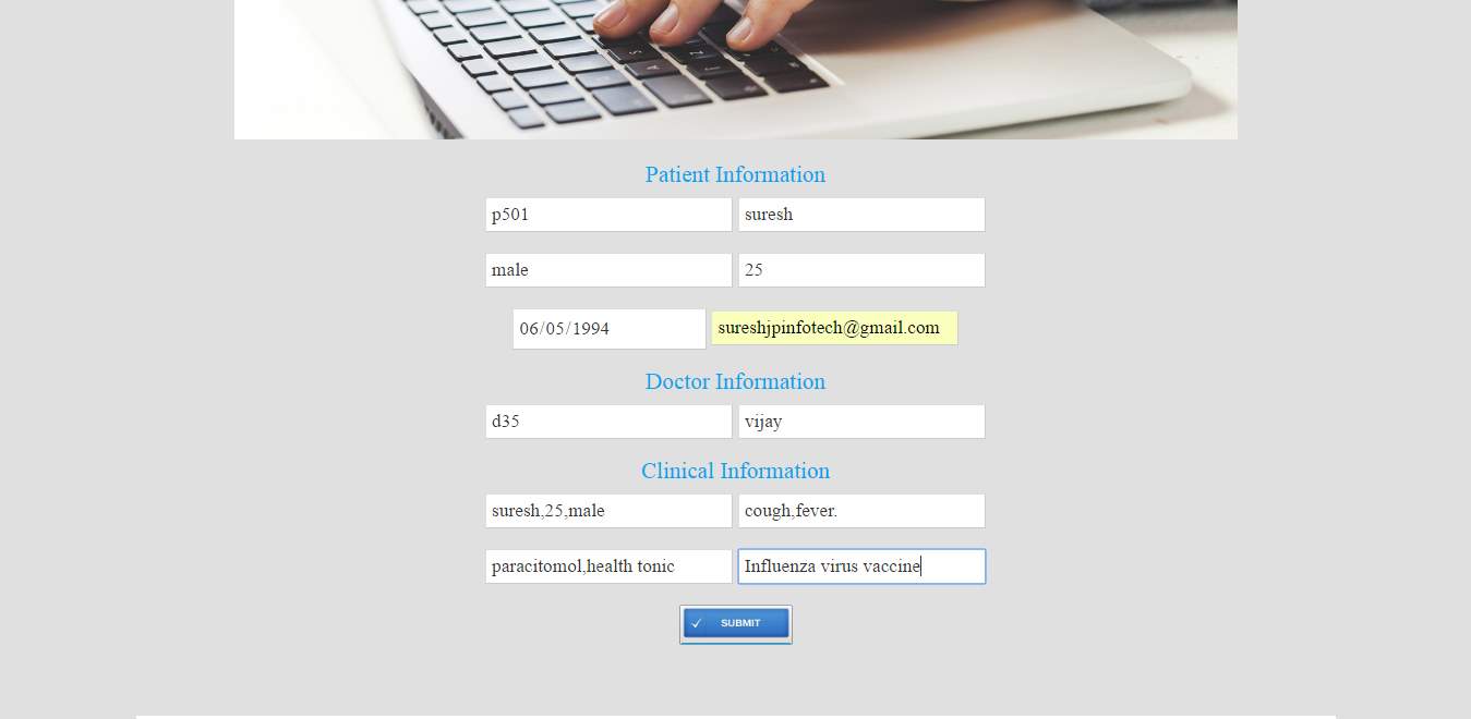
FIG 8.8 Patient information upload
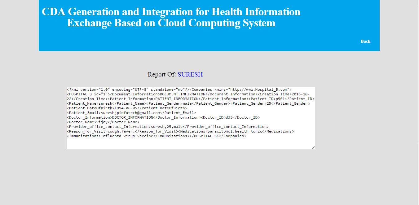
FIG 8.9 Hospital B patient information
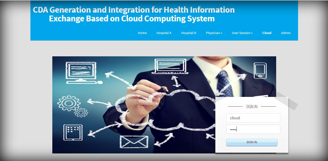
FIG 8.10 Cloud login
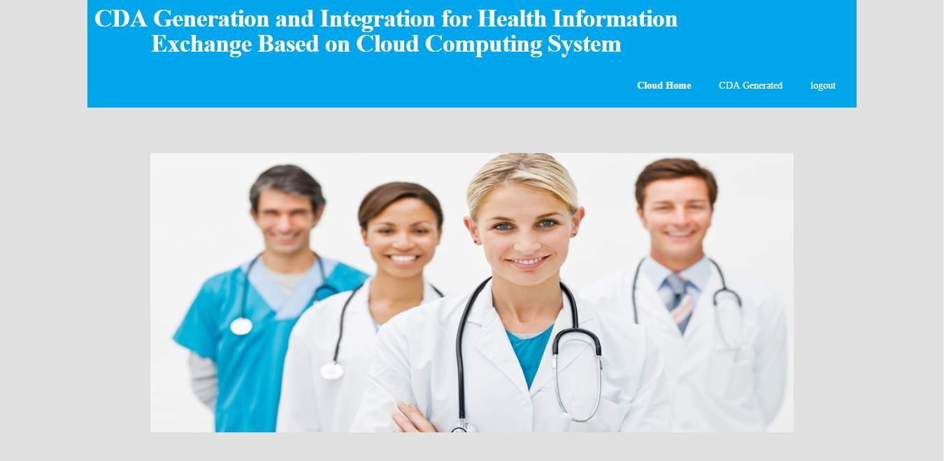
FIG 8.11 Cloud home
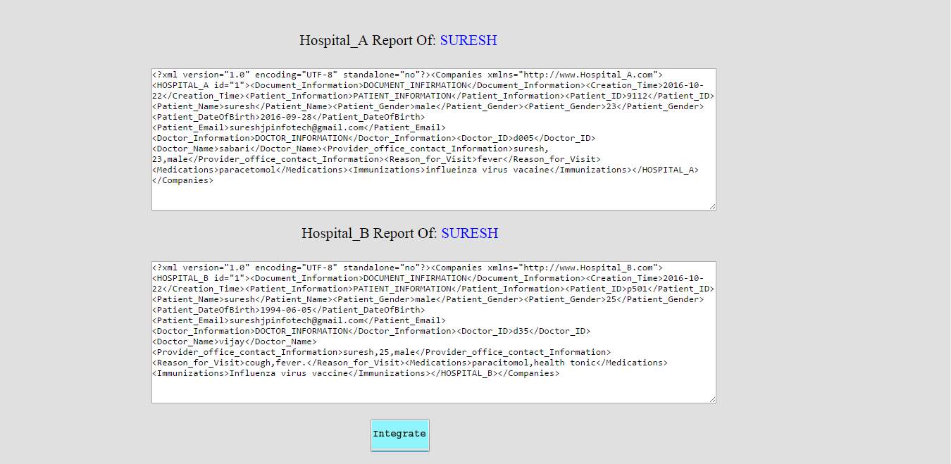
FIG 8.12 Integration of A&B hospital records
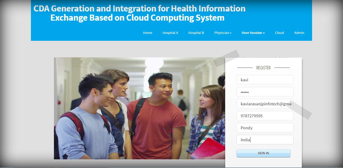
FIG 8.13 Patient registration
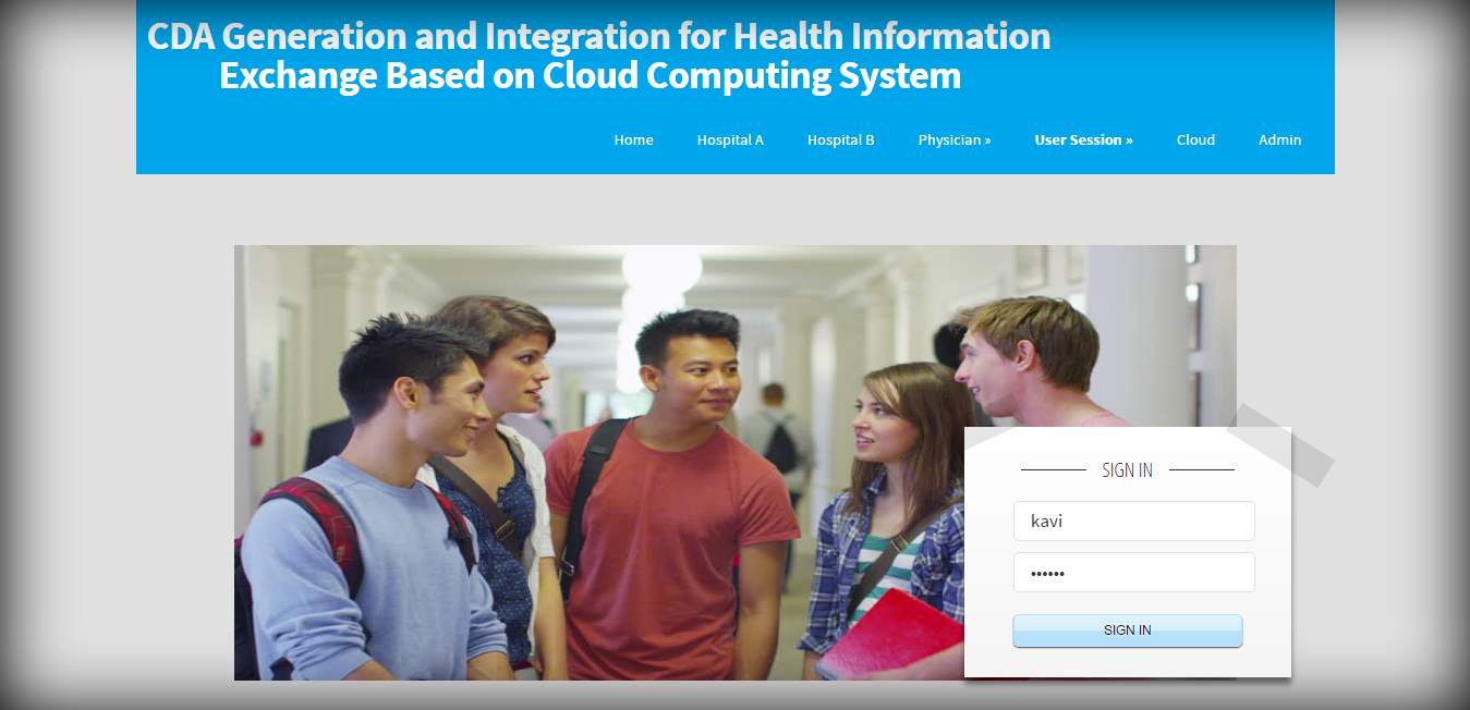
FIG 8.14 Patient login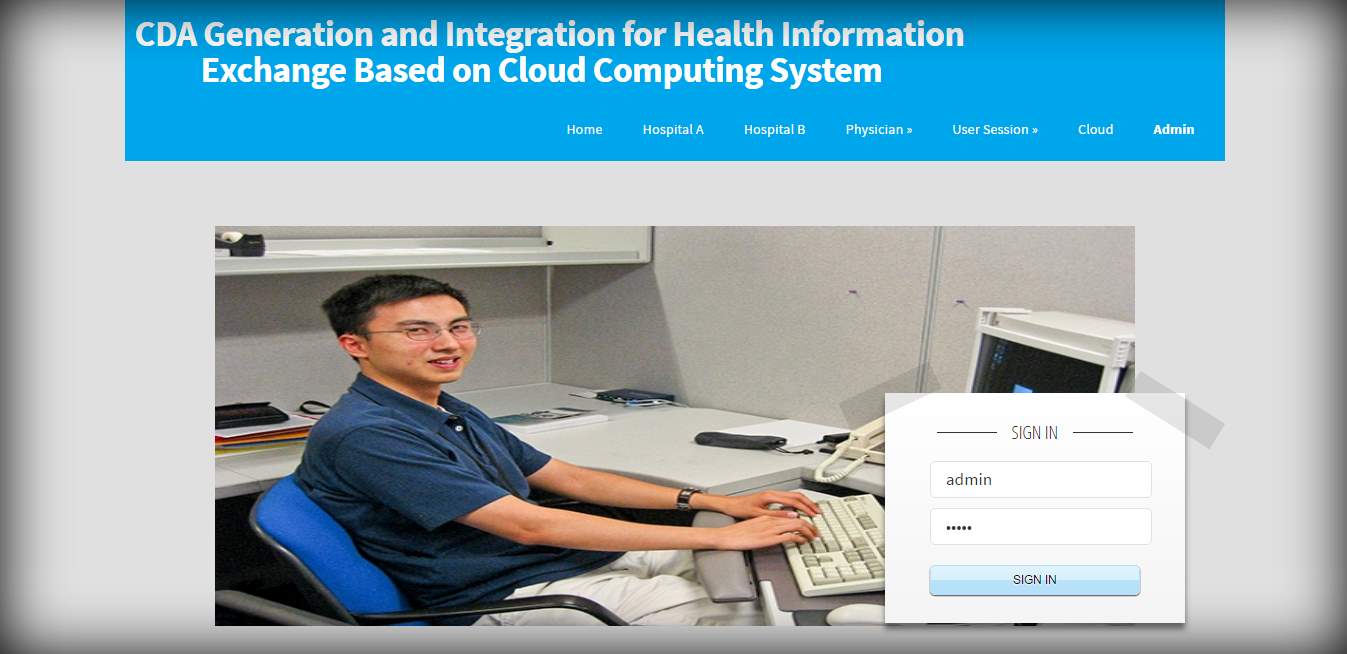
FIG 8.15 Admin login
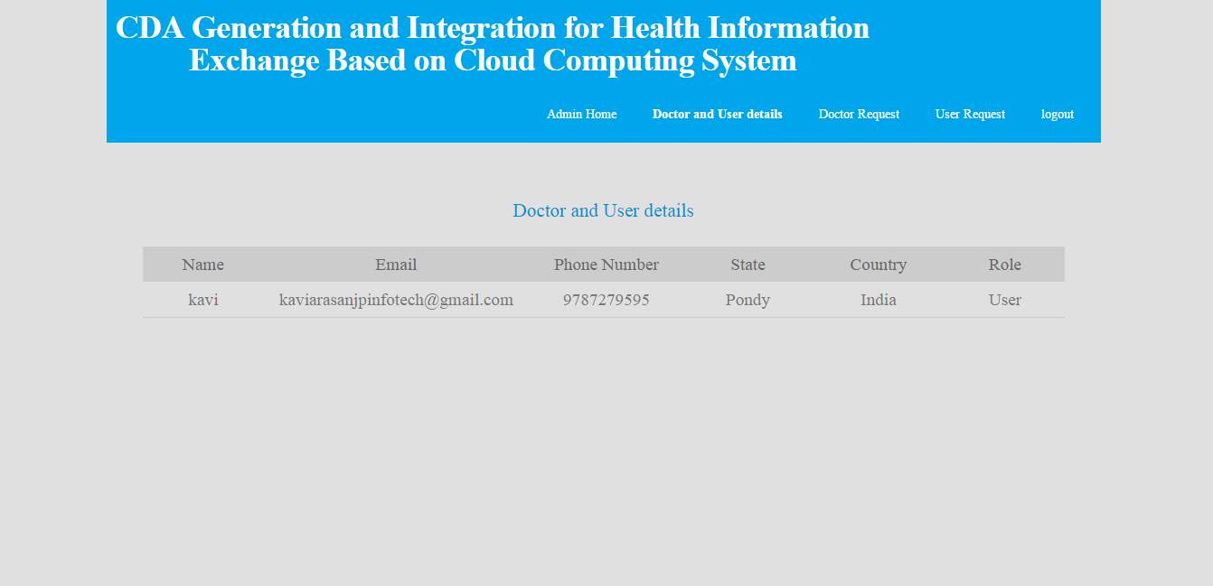
FIG 8.16 Patient information page
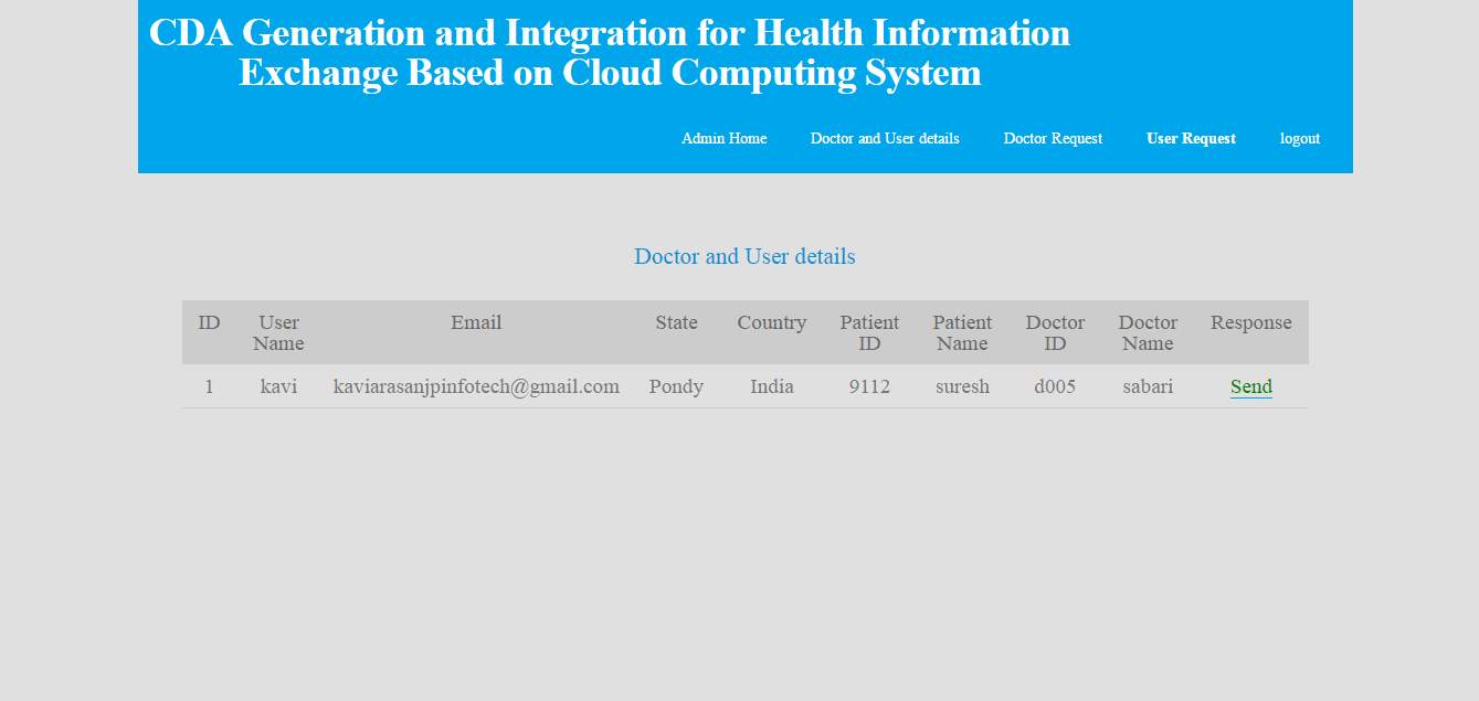
FIG 8.17 Admin view page for permission
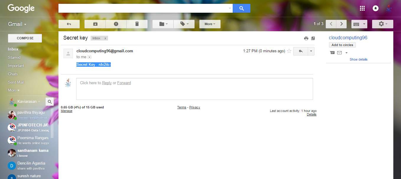
FIG 8.18 CDA keys are sent to mail id
FIG 8.19 Doctor sign in
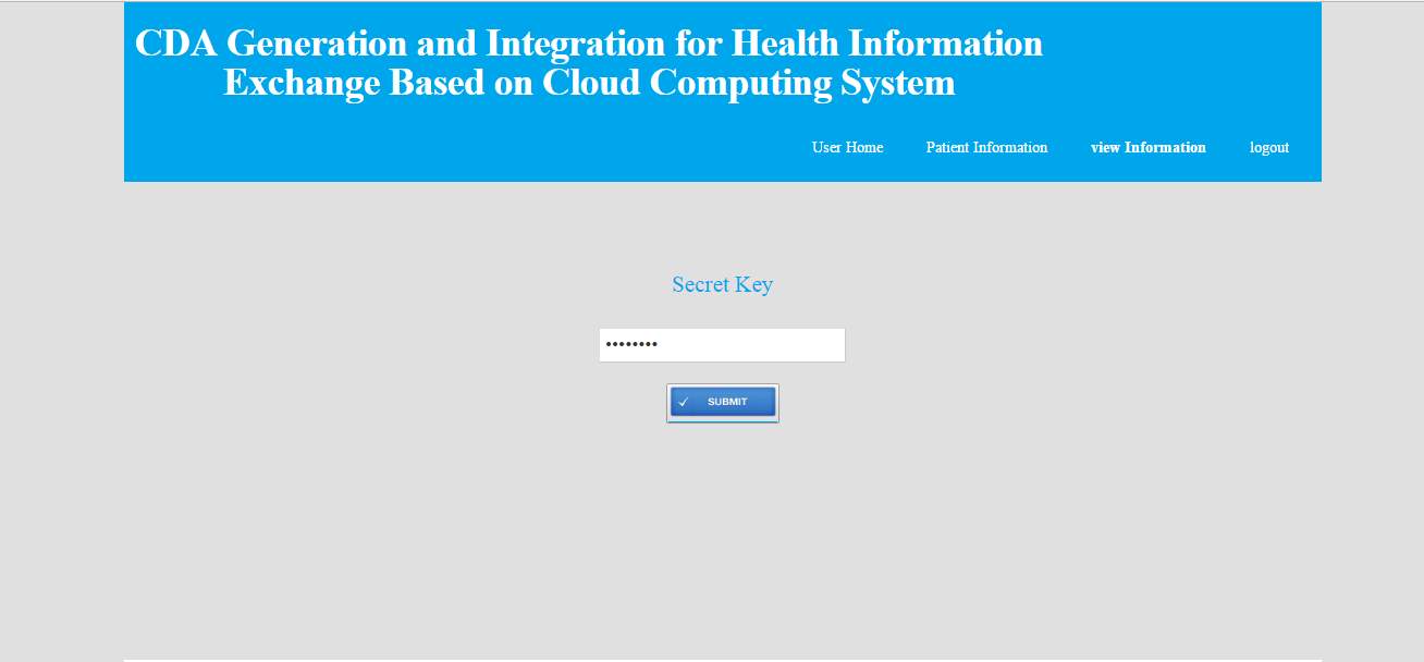
FIG 8.20 CDA key entry
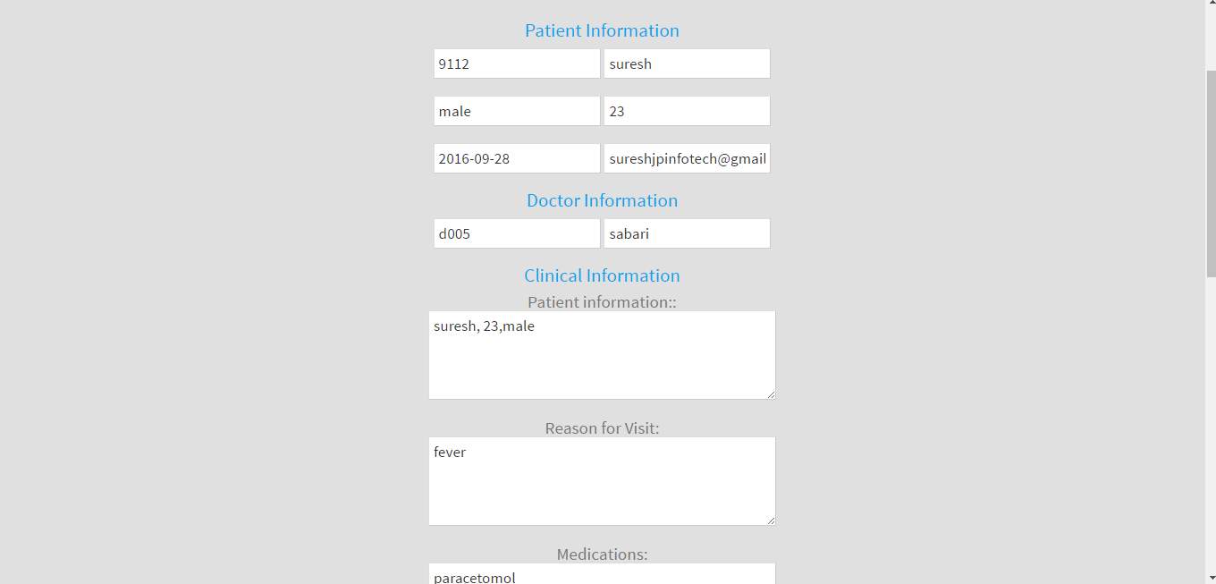
FIG 8.21 Patient medical record
..
9. CONCLUSION
As the number of HIE based on CDA documents increases, interoperability is achieved, but it also brings a problem where managing various CDA documents per patient becomes inconvenient as the clinical information for each patient is scattered in different documents. The CDA document integration service from our cloud server adequately addresses this issue by integrating multiple CDA documents that have been generated for individual patients. The clinical data for the patient in question is provided to his/her doctor in chronological order per section so that it helps physicians to practice evidence-based medicine. In the field of document-based health information exchange, the IHE XDS profile is predominant and our cloud computing system can be readily linked with the IHE XDS profile.
The approach employed in this paper is applicable in adopting other standards, too, such as the EHR Extract based on openEHR. If a hospital sends the content archetype, admin archetype, and demographic archetype to the cloud server, then the server extracts necessary information from each archetype. Next, it generates an Extract containment structure that fits with a designated template and returns the structure to the requested hospital.
- FUTURE SCOPE
CDA is a upcoming clinical advanced document model that combines both the security and authentication of the information.Using this helps analyse the clinical data .it decreases the space and provides the security for the clinical data.It can easily measurable and can identify the patient condition and diseases.
- BIBLIOGRAPHY
References Made From:
] Y. Kwak, “International standards for building electronic health record (ehr),” in Proc. Enterprise Netw. Comput. Healthcare Ind., pp. 18–23, Jun. 2005.
[2] M. Eichelberg, T. Aden, J. Riesmeier, A. Dogac, and Laleci, “A survey and analysis of electronic healthcare record standards,” ACM Comput. Surv., vol. 37, no. 4, pp. 277–315, 2005.
[3] T. Benson, Principles of Health Interoperability HL7 and SNOMED. New York, NY, USA: Spinger, 2009.
[4] J. L€ ahteenm€ aki, J. Lepp€ anen, and H. Kaijanranta, “Interoperability of personal health records,” in Proc. IEEE 31st Annu. Int. Conf. Eng. Med. Biol. Soc., pp. 1726–1729, 2009.
[5] R. H. Dolin, L. Alschuler, C. Beebe, P. V. Biron, S. L. Boyer, D. Essin, E. Kimber, T. Lincoln, and J. E. Mattison, “The HL7 Clinical Document Architecture,” J. Am. Med. Inform. Assoc., vol. 8, pp. 552–569, 2001.
Cite This Work
To export a reference to this article please select a referencing stye below:
Related Services
View all


Related Content
All TagsContent relating to: "Information Systems"
Information Systems relates to systems that allow people and businesses to handle and use data in a multitude of ways. Information Systems can assist you in processing and filtering data, and can be used in many different environments.
Related Articles

DMCA / Removal Request
If you are the original writer of this dissertation and no longer wish to have your work published on the UKDiss.com website then please: