Global System for Mobile Communication Control System
Info: 18077 words (72 pages) Dissertation
Published: 26th Jan 2022
Tagged: Information SystemsTechnology
CHAPTER 1 - INTRODUCTION
1.1 Aim
The main aim of the project is to turn ON and OFF a motor using GSM technology.
1.2 Objective
The main objective of this project is to control the motor. Control means ability to shut down a machine whenever we want to and in this project it is done with wireless signal transmission. Our objective is to give the motor proper protection. We give over voltage and under voltage protection by fetching feedback signals from the load end.
1.3 Overview
GSM based Control System” implements the emerging applications of the GSM technology. Using GSM networks, a control system has been proposed that will act as an embedded system which can monitor and control appliances and other devices locally using built-in input and output peripherals. Remotely the system allows the user to effectively monitor and control the house/office appliances and equipments via the mobile phone set by sending commands in the form of SMS messages and receiving the appliances status. The main concept behind the project is receiving the sent SMS and processing it further as required to perform several operations. The type of the operation to be performed depends on the nature of the SMS sent.
GSM (Global System for Mobile Communications): It is a cellular communication standard. SMS (Short Message Service): It is a service available on most digital mobile phones that permit the sending of short messages (also known as text messaging service). Technology has advanced so much in the last decade or two that it has made life more efficient and comfortable. The comfort of being able to take control of devices from one particular location has become imperative as it saves a lot of time and effort. Therefore there arises a need to do so in a systematic manner which we have tried to implement with our system. The system we have proposed is an extended approach to automating a control system.
1.4 Literature survey
Goodman, D.J. (1) has worked on various Trends in cellular and cordless communications and suggested four second generation networks. In the framework of these issues, 4 networks are described. Turnell, D.J.; Deep, G.S.; Freire, R.C.S.(2) designed a lowcost water detection method for furrow irrigation control in which a computer monitors the water advance along the furrows during the initial phase of the irrigation. The detection of water is done by the change in capacitance of a wire element.
Moon, Y.S.; Wong, K.; Ho, K.S. (3) has designed a prototype of a novel GSM mobile phone based automobile security system. Experimental results show that the approach is feasible even for the low bandwidth of the GSM network. Wall, R.W. (4) suggested Sprinklers and power lines for implementing precision agriculture for farm management requires improved sensing and control. It is also shown how to reduce operating costs for automating existing agricultural irrigation controls View.
Askarian, Abyaneh, H.; Al-Dabbagh, M.; Kazemi, Karegar, H.; Hesameddin, Hossein Sadeghi, S.; Abul Jabbar Khan, R. (5) have suggested a New Optimal Approach for Coordination of Overcurrent Relays in Interconnected Power Systems. The authors also make recommendations on how calibrations of reference measuring systems should be performed. Alessandro Andreadis, Giuliano Benelli, Giovanni Giambene, and Bernardo Marzucchi (6) have suggested A Performance Evaluation Approach for GSM-Based Information Services which focuses on the Wireless Application Protocol (WAP) for providing mobile information services, as envisaged by the Personalized Access to Local Information and Services for Tourists (PALIO) project.
Hui-Nien Hung, Yi-Bing Lin, Fellow, IEEE, Ming-Kun Lu, and Nan-Fu Peng (7) developed A Statistic Approach for Deriving the Short Message Transmission Delay Distributions which analyzes the short message transmission delays based on 40 000 measured data collected from commercial operation. AI-Ali A. R., & Rousan M., Mohandes M.,(8) have designed GSM based distribution transformer monitoring system. The system can be also controlled and monitored from anywhere by using telephone line.
Chakravorty R., Clark A., and Ian Pratt,(9) show what causes the web and its underlying transport protocol TCP to underperform in a GPRS wide-area wireless environment. They examine why certain GPRS network characteristics interact badly with TCP to yield problems such as: link underutilization for short-lived flows, excess queueing for long-lived flows, ACK compression, poor loss recovery, and gross unfairness between competing flows. Carlos H. S., Mario Pascual Carrasco, González de Mingo, Adolfo Muñoz C., Joaquin Márquez Montes, Luis Sosa Martín, Miguel A., Ignacio Fernández Lozano, and José Luis Monteagudo, (10) provide a platform built around three information entities (patient, health-care_agent, and central_station) which was designed to enable patients with chronic heart disease to complete specifically defined protocols for out-of-hospital follow-up and monitoring.
CHAPTER 2 - HARDWARE
2.1 GSM Modem
A GSM modem is a specialized type of modem which accepts a SIM card, and operates over a subscription to a mobile operator, just like a mobile phone. From the mobile operator perspective, a GSM modem looks just like a mobile phone. When a GSM modem is connected to a computer, this allows the computer to use the GSM modem to communicate over the mobile network. While these GSM modems are most frequently used to provide mobile internet connectivity, many of them can also be used for sending and receiving SMS and MMS messages. A GSM modem can be a dedicated modem device with a serial, USB or Bluetooth connection, or it can be a mobile phone that provides GSM modem capabilities. Phones that use the S60 (Series 60) interface, which is Symbian based, only support sending SMS messages via the modem interface, and do not support receiving SMS via the modem interface.
GSM is the most popular standard for mobile telephone system in the world. The GSM association, It’s promoting industry trade organization of mobile phone carriers and manufacturers, estimates that 80% of the global mobile market uses the standards. GSM is used by over two billion people across more than 212 countries and territories.
It is ubiquity enables international roaming arrangements between mobile phone operators, providing subscribers the use of their phones in many parts of the world. GSM differs from it’s predecessor technologies in that both signalling and speech channels or digital, and thus GSM is considered a second generation mobile phone system. This also facilitates the wide-spread implementation of data communication applications in to the system.
A GSM modem can be a external unit or a PCMCIA card. An external GSM modem connected to a PC through a serial cable, a USB cable, Bluetooth or infrared. Like a GSM mobile phone, a GSM modem requires a SIM card from a wireless carrier in order to operate.
GSM is a cellular network which means that mobile phones connected to it by searching for cells in the immediate vicinity. There are five different cell sizes in a GSM network- macro, micro, Pico, feta and umbrella cells. The coverage area of each cell varies according to the implementation environment. Macro cells can be regarded as cells where the base station antenna in installed on a master or a building above average roof top level.
The ubiquity of implementation of the GSM standard has a an advantage to both consumers, who may benefit from the ability to roam and switch without replacing, phones, and also to network operators, who can choose equipment from many GSM equipment vendors. GSM also pioneered low-cost implementation of the short message service, also called text messaging.
Micro cells are cells whose antenna height is under average roof top level; they are typically used in urban areas. Pico cells are small cells whose coverage diameter is a few dozen meters; they are mainly used indoors. Fetal cells are cells designed for use in residential or small businesses environment and connect to the service provider’s network via broad band internet connection. Umbrella cells are used to cover shadowed regions of smaller cells fill in gaps in coverage between those cells.
2.1.1 Architecture of GSM network
The GSM technical specifications define the different elements within the GSM network architecture. It defines the different elements and the ways in which they interact to enable the overall system operation to be maintained.
The GSM network architecture is now well established and with the other later cellular systems now established and other new ones being deployed, the basic GSM network architecture has been updated to interface to the network elements required by these systems.
Despite the developments of the newer systems, the basic GSM system architecture has been maintained, and the network elements described below perform the same functions as they did when the original GSM system was launched in the early 1990s.GSM network architecture elements
The GSM network architecture as defined in the GSM specifications can be grouped into four main areas:
- Mobile station (MS)
- Base-Station Subsystem (BSS)
- Network and Switching Subsystem (NSS)
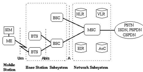
fig2.1:architecture of GSM
Mobile Station
The mobile station (MS) consists of the mobile equipment (the terminal) and a smart card called the Subscriber Identity Module (SIM). The SIM provides personal mobility, so that the user can have access to subscribed services irrespective of a specific terminal. By inserting the SIM card into another GSM terminal, the user is able to receive calls at that terminal, make calls from that terminal, and receive other subscribed services.
The mobile equipment is uniquely identified by the International Mobile Equipment Identity (IMEI). The SIM card contains the International Mobile Subscriber Identity (IMSI) used to identify the subscriber to the system, a secret key for authentication, and other information. The IMEI and the IMSI are independent, thereby allowing personal mobility. The SIM card may be protected against unauthorized use by a password or personal identity number.
Base Station Subsystem
The Base Station Subsystem is composed of two parts, the Base Transceiver Station (BTS) and the Base Station Controller (BSC). These communicate across the standardized Abis interface, allowing (as in the rest of the system) operation between components made by different suppliers.
Base Transceiver Station(BTS): houses the radio transceivers that define a cell and handles the radio-link protocols with the Mobile Station.
Base Station Controller(BSC): manages the radio resources for one or more BTS’s. It handles radio-channel setup, frequency hopping, and handovers, as described below. The BSC is the connection between the mobile station and the Mobile service Switching Centre (MSC).
Network Subsystem
Mobile services Switching Center(MSC): the central component of the Network Subsystem . It acts like a normal switching node of the PSTN or ISDN, and additionally provides all the functionality needed to handle a mobile subscriber, such as registration, authentication, location updating, handovers, and call routing to a roaming subscriber. These services are provided in conjuction with several functional entities, which together form the Network Subsystem. The MSC provides the connection to the fixed networks (such as the PSTN or ISDN).
The Home Location Register (HLR) and Visitor Location Register (VLR), together with the MSC, provide the call-routing and roaming capabilities of GSM.
Home Location Register (HLR): contains all the administrative information of each subscriber registered in the corresponding GSM network, along with the current location of the mobile. The location of the mobile is typically in the form of the signalling address of the VLR associated with the mobile station. There is logically one HLR per GSM network, although it may be implemented as a distributed database.
Visitor Location Register (VLR): contains selected administrative information from the HLR, necessary for call control and provision of the subscribed services, for each mobile currently located in the geographical area controlled by the VLR. Although each functional entity can be implemented as an independent unit, all manufacturers of switching equipment to date implement the VLR together with the MSC, so that the geographical area controlled by the MSC corresponds to that controlled by the VLR, thus simplifying the signalling required. Note that the MSC contains no information about particular mobile stations — this information is stored in the location registers.
The other two registers are used for authentication and security purposes.
Equipment Identity Register (EIR): is a database that contains a list of all valid mobile equipment on the network, where each mobile station is identified by its International Mobile Equipment Identity (IMEI). An IMEI is marked as invalid if it has been reported stolen or is not type approved.
Authentication Centre(AuC): is a protected database that stores a copy of the secret key stored in each subscriber’s SIM card, which is used for authentication and encryption over the radio channel.
2.1.2 Neoway M680
Here we are using Neoway M680 GSM modem.
Overview
M680 is a compact wireless GSM/GPRS module that supports downlink edge. It can provide functions for high-quality voice, SMS, and data services and is widely used in industrial and civil fields. This document defines the features, indicators, and test standards of the M680 module.
Block Diagram
The M680 module consists of baseband controller, Flash ROM, RF section, application interfaces, etc. All sections coordinate with each other to provide such communication functions as GPRS data and voice.
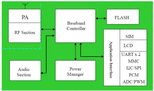
fig 2.2:block diagram of GSM module
Specifications
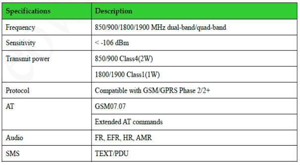
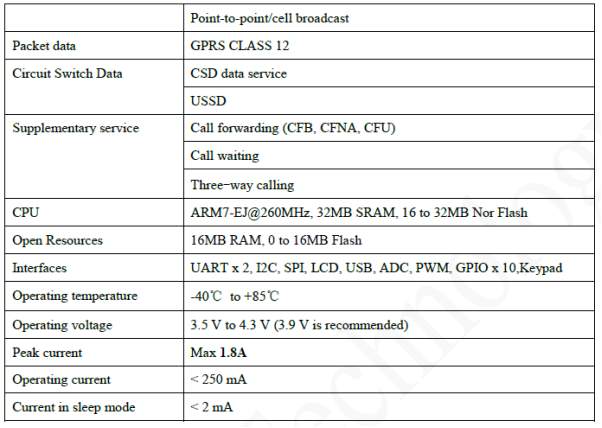
table 2.1:specifications of GSM module
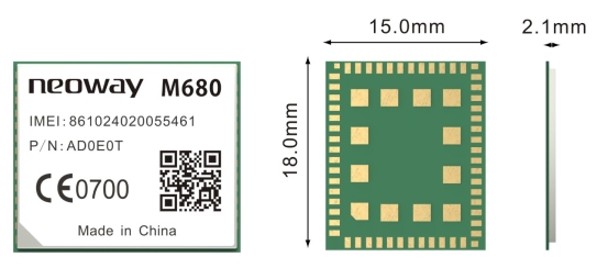
fig 2.3:neoway m680
Temperature and Test Standards
- Operating temperature: –40°C to + 85°C
- Storage temperature: –40°C to + 85°C
- Humidity: 0% to 95%
EMI/EMC Index and Test Standards
- ESD anti-interference
− Contact discharge: test voltage 4 kV
− Air discharge: test voltage 8 kV
- RF immunity to electromagnetic radiation
− Radiation intensity 10 V/M (frequency range: 80 MHz to 1000 MHz)
- Radio continuous disturb
− Test range: 30 MHz to 1 GHz (peak value & average value)
- Radio stray disturb
− Test range: 30 MH to 6000 MHz
Mounting the Module onto the Application Board
M680 is compatible with industrial standard reflow profile for lead-free SMT process. The reflow profile is process dependent, so the following recommendation is just a start point guideline:
- Only one flow is supported.
- Quality of the solder joint depends on the solder volume. Minimum of 0.15mm stencil thickness is recommended.
- Use bigger aperture size of the stencil than actual pad size.
- Use a low-residue, no-clean type solder paste.
Package
M680 modules are packaged in sealed bags on delivery to guarantee a long shelf life. Package the modules again in case of opening for any reasons. If exposed in air for more than 48 hours at conditions not worse than 30°C/60% RH, a baking procedure should be done before SMT. Or, if the indication card shows humidity greater than 20%, the baking procedure is also required.
The baking should last for at least 12 hours at 90℃.
PCB FOOTPRINT
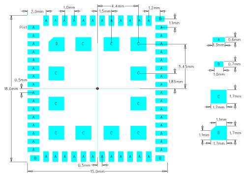
fig 2.4:footprint of neoway m680
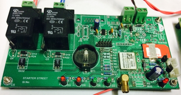
fig2.5:GSM kit
2.2 Power Supply
A power supply is a device that supplies electric power to an electrical load. The term is most commonly applied to electric power converters that convert one form of electrical energy to another, though it may also refer to devices that convert another form of energy (mechanical, chemical, solar) to electrical energy. A regulated power supply is one that controls the output voltage or current to a specific value; the controlled value is held nearly constant despite variations in either load current or the voltage supplied by the power supply’s energy source. A compound DC motor connects the armature and fields windings in a shunt and a series combination to give it characteristics of both a shunt and a series DC motor. This motor is used when both a high starting torque and good speed regulation is needed. The motor can be connected in two arrangements: cumulatively or differentially.
An AC powered unregulated power supply usually uses a transformer to convert the voltage from the wall outlet (mains) to a different, nowadays usually lower, voltage. If it is used to produce DC, a rectifier is used to convert alternating voltage to a pulsating direct voltage, followed by a filter, comprising one or more capacitors, resistors, and sometimes inductors, to filter out (smooth) most of the pulsation. A small remaining unwanted alternating voltage component at mains or twice mains power frequency (depending upon whether half- or full-wave rectification is used)— ripple—is unavoidably superimposed on the direct output voltage.
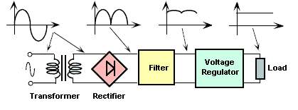
fig2.6:block diagram of power supply
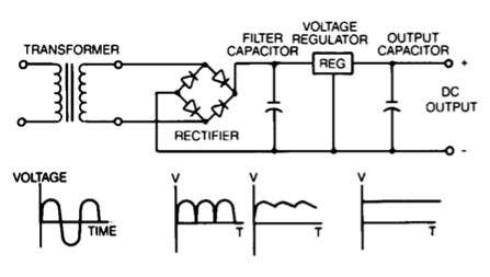
fig:2.7:circuit diagram of power supply
The power supply unit is the piece of hardware that’s used to convert the power provided from the outlet into usable power for the many parts inside the computer case.
It converts the alternating current (AC) into a continuous form of power that the computer components need in order to run normally, called direct current (DC). It also regulates overheating by controlling voltage, which may change automatically or manually depending on the power supply.
Unlike some hardware components used with a computer that isn’t necessarily needed, as a printer, the power supply is a crucial piece because, without it, the rest of the internal hardware can’t function.
The power supply unit is often abbreviated as PSU and is also known as a power pack or power converter.
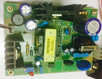
fig 2.8:power supply kit
The power supply unit is mounted just inside the back of the case. If you follow the computer’s power cable, you’ll find that it attaches to the back of the power supply.It’s the backside that’s usually the only portion of the power supply that most people will ever see. There’s also a fan opening at the back of the power supply that sends air out the back of the computer case. The side of the PSU facing outside the case has a male, three-pronged port that a power cable, connected to a power source, plugs into.There is also often a power switch and a power supply voltage switch.
Large bundles of colours wires extend from the opposite side of the power supply unit into the computer. Connectors at the opposite ends of the wires connect to various components inside the computer to supply them with power. Some are specifically designed to plug into the motherboard while others have connectors that fit into fans, floppy drives, hard drives, optical drives, and even some high powered video cards. Power supply units are rated by wattage to show how much power they can provide to the computer. Since each computer part requires a certain amount of power to function properly, it’s important to have a PSU that can provide the right amount. The very handy Cooler Master Supply Calculator tool can help you determine how much you need.
2.2.1 TRANSFORMER
A transformer is a static electrical device that transfers energy by inductive coupling between its winding circuits. A varying current in the primary winding creates a varying magnetic flux in the transformer’s core and thus a varying magnetic flux through the secondary winding. This varying magnetic flux induces a varying electromotive force (EMF) or voltage in the secondary winding. Transformers range in size from thumbnail-sized used in microphones to units weighing hundreds of tons interconnecting the power grid. A wide range of transformer designs are used in electronic and electric power applications. Transformers are essential for the transmission, distribution, and utilization of electrical energy
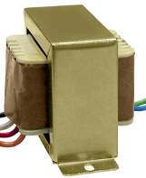
fig2.9:transformer
2.2.2 RECTIFIER
A rectifier is an electrical device that converts alternating current (AC), which periodically reverses direction, to direct current (DC), which flows in only one direction. The process is known as rectification. Physically, rectifiers take a number of forms, including vacuum tube diodes, mercury-arc valves, copper and selenium oxide rectifiers, solid-state diodes, silicon controlled rectifiers and other silicon-based semiconductor switches. Historically, even synchronous electromechanical switches and motors have been used. Early radio receivers, called crystal radios, used a “cat’s whisker” of fine wire pressing on a crystal of galena (lead sulfide) to serve as a point-contact rectifier or “crystal detector”.
Rectifiers have many uses, but are often found serving as components of DC power supplies and high-voltage direct current power transmission systems. Rectification may serve in roles other than to generate direct current for use as a source of power. As noted, detectors of radio signals serve as rectifiers. In gas heating systems flame rectification is used to detect presence of flame. The simple process of rectification produces a type of DC characterized by pulsating voltages and currents (although still unidirectional). Depending upon the type of end-use, this type of DC current may then be further modified into the type of relatively constant voltage DC characteristically produced by such sources as batteries and solar cells.
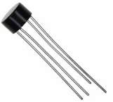
fig2.10:rectifier
2.2.3 VOLTAGE REGULATOR
A voltage regulator is designed to automatically maintain a constant voltage level. A voltage regulator may be a simple “feed-forward” design or may include negative feedback control loops. It may use an electromechanical mechanism, or electronic components. Depending on the design, it may be used to regulate one or more AC or DC voltages. Electronic voltage regulators are found in devices such as computer power supplies where they stabilize the DC voltages used by the processor and other elements. In automobile alternators and central power station generator plants, voltage regulators control the output of the plant. In an electric power distribution system, voltage regulators may be installed at a substation or along distribution lines so that all customers receive steady voltage independent of how much power is drawn from the line.
A linear regulator employs an active (BJT or MOSFET) pass device (series or shunt) controlled by a high gain differential amplifier. It compares the output voltage with a precise reference voltage and adjusts the pass device to maintain a constant output voltage.
A switching regulator converts the dc input voltage to a switched voltage applied to a power MOSFET or BJT switch. The filtered power switch output voltage is fed back to a circuit that controls the power switch on and off times so that the output voltage remains constant regardless of input voltage or load current changes.
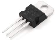
fig2.11:voltage regulator
2.3 MOTOR
A pump is a device that moves fluids (liquids or gases), or sometimes slurries, by mechanical action. Pumps can be classified into three major groups according to the method they use to move the fluid: direct lift, displacement, and gravity pumps.
Pumps operate by some mechanism (typically reciprocating or rotary), and consume energy to perform mechanical work by moving the fluid. Pumps operate via many energy sources, including manual operation, electricity, engines, or wind power, come in many sizes, from microscopic for use in medical applications to large industrial pumps.
Mechanical pumps serve in a wide range of applications such as pumping water from wells, aquarium filtering, pond filtering and aeration, in the car industry for water-cooling and fuel injection, in the energy industry for pumping oil and natural gas or for operating cooling towers. In the medical industry, pumps are used for biochemical processes in developing and manufacturing medicine, and as artificial replacements for body parts, in particular the artificial heart and penile prosthesis.
Single stage pump – When in a casing only one impeller is revolving then it is called single stage pump.
Double/ Multi stage pump – When in a casing two or more than two impellers are revolving then it is called double/ multi stage pump.
Water pumps move water that does not contain suspended solids or particulates. These pumps are not so much a type of pump as they are a classification based on the media being transferred. Nearly every pump type that is defined by either a complementary application (fountain water pumps, submersible water pumps) or by motive type (such as centrifugal, cantilever, or hand water pumps) can be used in water service applications.
2.3.1 Types
While slurries and the like are best handled by wastewater or sewage pumps, water pumps can handle clear water such as these types:
1. Condensate pumps transport or collect and transport condensate collected from a steam system back into the system for reheating and reuse. These pumps close the boiler-steam-condensate loop by returning hot condensate back to the system. This takes advantage of valuable BTUs, which would otherwise go to waste. Condensate pumps can also be used for the removal of unwanted condensate from an HVAC or appliance collection pan.
2. Ground water pumps pump untreated water that is found on or collects freely on the ground.
3. Potable water pump move water that is considered safe and fit for human consumption, culinary and domestic purposes and meets the requirements of the health authority having jurisdiction.
4. Salt water pumps pump water that has a high concentration of salt, often from the ocean.
2.3.2 Specifications
When selecting a water pump, flow discharge pressure, material of construction, and power source are key criteria to understand. In order to evaluate flow output, it is critical to consider the pressure or head that the pump is working against. Always consult the manufacturer’s pump curve to determine the actual flow at any given pressure. All pumps have a maximum pressure that they can pump against, and the pump’s flow output diminishes as the pressure they are pumping against increases.
Maximum discharge flow: The maximum flow the pump is designed to generate. This value is dependent on the system or pressure head the pump must enter.
Maximum discharge pressure: The maximum pressure the pump is capable of generating while staying within design restraints.
2.3.3 Power Source
There are a variety of power sources that are used to operate water pumps. Power source comes down to availability, safety, and in many cases, portability. If the pump is not supplied with a power source the pump mechanism is the only power source. Typically, a drive shaft for connection of motor or other power source is provided.
- AC voltage
- DC voltage
- Compressed or pneumatic air source
- Gasoline or diesel engine
- Hydraulic system
- Manual
- Natural gas
- Solar powered
- Steam
- Water
2.3.4 Material
Material of construction is another key factor to consider when selecting a water pump. Care should be taken to choose a material that is best suited for the media and application in which the pump is to operate.
1. Aluminium is a bluish silver-white malleable ductile light trivalent metallic element that has good electrical and thermal conductivity, high reflectivity, and resistance to oxidation.
2. Brass or bronzes comes with good strength, excellent high temperature ductility and reasonable cold ductility, good conductivity, excellent corrosion resistance, good bearing properties and low magnetic permeability.
3. Cast iron refers not to a single material, but to a family of materials whose major constituent is iron, with important trace amounts of carbon and silicon. Cast irons are natural composite materials whose properties are determined by their microstructures – the stable and metastable phases formed during solidification or subsequent heat treatment.
4. Plastics are any of various organic compounds produced by polymerization, capable of being molded, extruded, cast into various shapes and films, or drawn into filaments used as textile fibers.
5. Stainless steel is chemical and corrosion resistant and can have relatively high pressure ratings.
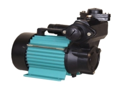
fig 2.12:ac motor
2.4 MOTOR STARTER
Starter could be a device that connects with motor nonparallel to decrease the present at commencement and increase current when beginning the motor (in alternative words begin or stop the motor) and supply overload protection.
A Starter could be a device that controls the utilization of wattage to instrumentality, typically a motor. because the name implies, starters “start” motors. they will additionally stop them, reverse them, and shield them. Starters area unit made up of 2 building blocks, Contractors and Overload Protection.
1. Contactors management the electrical current to the motor. Their perform is to repeatedly establish Associate in Nursingd interrupt an wattage circuit.
2. Overload Protection protects motors from drawing an excessive amount of current, warming, and from virtually “burning out”.
A starter turns an electrical motor or motor controlled electrical instrumentality on or off, whereas providing overload protection. Starters represent another evolution in control applications. the 2 main styles of starters area unit Manual Starters and AC Magnetic Motor Starters, normally called Motor Starters.
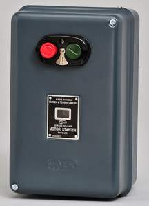
fig 2.13:motor starter
2.4.1 Features
All motor starters share the following power control functions:
- Rated by current (amperes) or power (horsepower)
- Remote ON/OFF control
- Motor overload protection
- Starting and stopping (electrical life)
- Plugging and jogging (rapid making and breaking current)
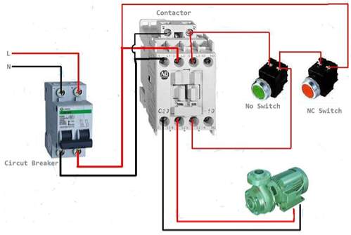
fig2.14:motor starter connections
2.5 RELAY
A relay is associate electrically operated switch. several relays use associate magnet to automatically operate a switch, however different operational principles also are used, like solid-state relays. Relays area unit used wherever it’s necessary to manage a circuit by a separate low-power signal, or wherever many circuits should be controlled by one signal. the primary relays were employed in long distance telegraph circuits as amplifiers: they continual the signal returning in from one circuit and re-transmitted it on another circuit. Relays were used extensively in phonephone exchanges and early computers to perform logical operations.
A type of relay that may handle the high power needed to directly management an electrical motor or different hundreds is termed a contactor. Solid-state relays management power circuits with no moving components, instead employing a semiconductor unit to perform change. Relays with mark operational characteristics and generally multiple operational coils area unit wont to defend electrical circuits from overload or faults; in fashionable power systems these functions area unit performed by digital instruments still referred to as “protective relays”.
Magnetic latching relays need one pulse of coil power to maneuver their contacts in one direction, and another, redirected pulse to maneuver them back. continual pulses from an equivalent input don’t have any impact. Magnetic latching relays area unit helpful in applications wherever interrupted power mustn’t be able to transition the contacts.
Magnetic latching relays will have either single or twin coils. On one coil device, the relay can operate in one direction once power is applied with one polarity, and can reset once the polarity is reversed. On a twin coil device, once polarized voltage is applied to the reset coil the contacts can transition. AC controlled magnetic latch relays have single coils that use steering diodes to differentiate between operate and reset commands.
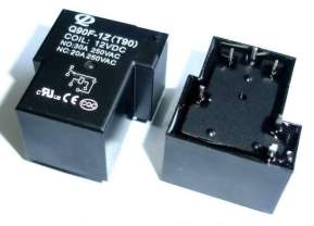
fig2.15:relay q90f
2.5.1 Basic design and operation
A simple magnetism relay consists of a coil of wire wrapped around a soft iron core, associate iron yoke that provides an occasional reluctance path for magnetic flux, a movable iron coil, and one or a lot of sets of contacts (there ar 2 contacts within the relay pictured). The coil is hinged to the yoke and automatically connected to at least one or a lot of sets of moving contacts. The coil is command in situ by a spring in order that once the relay is de-energized there’s associate air gap within the magnetic circuit.
In this condition, one amongst the 2 sets of contacts within the relay pictured is closed, and also the different set is open. different relays might have a lot of or fewer sets of contacts looking on their operate. The relay within the image additionally features a wire connecting the coil to the yoke. This ensures continuity of the circuit between the moving contacts on the coil, and also the circuit track on the computer circuit board (PCB) via the yoke, that is soldered to the PCB.
When an electrical current is undergone the coil it generates a flux that activates the coil, and also the resultant movement of the movable contact(s) either makes or breaks (depending upon construction) a reference to a set contact. If the set of contacts was closed once the relay was de-energized, then the movement opens the contacts and breaks the affiliation, and the other way around if the contacts were open. once the present to the coil is shifted, the coil is came back by a force, more or less [*fr1] as sturdy because the magnetic attraction, to its relaxed position. typically this force is provided by a spring, however gravity is additionally used normally in industrial motor starters.
When the coil is energized with DC, a diode is usually placed across the coil to dissipate the energy from the collapsing flux at deactivation, which might otherwise generate a voltage spike dangerous to semiconductor circuit parts. Such diodes weren’t wide used before the appliance of transistors as relay drivers, however shortly became present as early semiconductor transistors were simply destroyed by this surge. Some automotive relays embrace a diode within the relay case.
If the relay is driving an outsized, or particularly a reactive load, there is also the same drawback of surge currents round the relay output contacts. during this case a snubbed circuit (a electrical condenser and resistance in series) across the contacts might absorb the surge. fittingly rated capacitors and also the associated resistance ar oversubscribed as one packaged element for this commonplace use.
If the coil is intended to be energized with electrical energy (AC), some technique is employed to separate the flux into 2 out-of-phase parts that add along, increasing the minimum pull on the coil throughout the AC cycle. usually this can be through with atiny low copper “shading ring” crimped around a little of the core that makes the delayed, out-of-phase element that holds the contacts throughout the zero crossings of the management voltage.
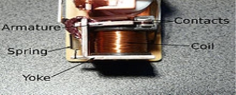
fig 2.16:internal structure of relay
2.6 ANTENNA
In radio and electronics, an antenna (plural antennae or antennas), or aerial, is an electrical device which converts electric power into radio waves, and vice versa.[1] It is usually used with a radio transmitter or radio receiver. In transmission, a radio transmitter supplies an electric current oscillating at radio frequency (i.e. a high frequency alternating current (AC) to the antenna’s terminals, and the antenna radiates the energy from the current as electromagnetic waves (radio waves). In reception, an antenna intercepts some of the power of an electromagnetic wave in order to produce a tiny voltage at its terminals, that is applied to a receiver to be amplified.
Typically an antenna consists of an arrangement of metallic conductors (elements), electrically connected (often through a transmission line) to the receiver or transmitter. An oscillating current of electrons forced through the antenna by a transmitter will create an oscillating magnetic field around the antenna elements, while the charge of the electrons also creates an oscillating electric field along the elements. These time-varying fields radiate away from the antenna into space as a moving transverse electromagnetic field wave. Conversely, during reception, the oscillating electric and magnetic fields of an incoming radio wave exert force on the electrons in the antenna elements, causing them to move back and forth, creating oscillating currents in the antenna.
Antennas can be designed to transmit and receive radio waves in all horizontal directions equally (omnidirectional antennas), or preferentially in a particular direction (directional or high gain antennas). In the latter case, an antenna may also include additional elements or surfaces with no electrical connection to the transmitter or receiver, such as parasitic elements, parabolic reflectors or horns, which serve to direct the radio waves into a beam or other desired radiation pattern.
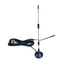
fig2.17:antenna
2.7 RESISTORS
A resistor is a passive two-terminal electrical component that implements electrical resistance as a circuit element. In electronic circuits, resistors are used to reduce current flow, adjust signal levels, to divide voltages, bias active elements, and terminate transmission lines, among other uses. High-power resistors that can dissipate many watts of electrical power as heat may be used as part of motor controls, in power distribution systems, or as test loads for generators.
Fixed resistors have resistances that only change slightly with temperature, time or operating voltage. Variable resistors can be used to adjust circuit elements (such as a volume control or a lamp dimmer), or as sensing devices for heat, light, humidity, force, or chemical activity.
Resistors are common elements of electrical networks and electronic circuits and are ubiquitous in electronic equipment. Practical resistors as discrete components can be composed of various compounds and forms. Resistors are also implemented within integrated circuits .The electrical function of a resistor is specified by its resistance: common commercial resistors are manufactured over a range of more than nine orders of magnitude.
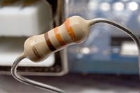
fig 2.18: resistor
2.8 CAPACITORS
The capacitor is a passive two terminal electrical electrical component that stores energy in an electric field. The effect of a capacitor is known as capacitance. While capacitance exists between any two electrical conductors of a circuit in sufficiently close proximity, a capacitor is specifically designed to provide and enhance this effect for a variety of practical applications by consideration of size, shape, and positioning of closely spaced conductors, and the intervening dielectric material. A capacitor was therefore historically first known as an electric condenser
The physical form and construction of practical capacitors vary widely and many capacitor types are in common use. Most capacitors contain at least two electrical conductors often in the form of metallic plates or surfaces separated by a dielectric medium. A conductor may be a foil, thin film, sintered bead of metal, or an electrolyte. The non conducting dielectric acts to increase the capacitor’s charge capacity. Materials commonly used as dielectrics include glass, ceramic, plastic film, paper, mica, and oxide layers. Unlike a resistor, an ideal capacitor does not dissipate energy.
When two conductors experience a potential difference, for example, when a capacitor is attached across a battery, an electric field develops across the dielectric, causing a net positive charge to collect on one plate and net negative charge to collect on the other plate. No current actually flows through the dielectric, however, there is a flow of charge through the source circuit.
Capacitance is defined as the ratio of the electric charge on each conductor to the potential difference between them. The unit of capacitance in the International System of Units (SI) is the farad (F), defined as one coulomb per volt (1 C/V The capacitance of a capacitor is proportional to the surface area of the plates (conductors) and inversely related to the gap between them. In practice, the dielectric between the plates passes a small amount of leakage current. It has an electric field strength limit, known as the breakdown voltage. The conductors and leads introduce an undesired inductance and resistance.
Capacitors are widely used in electronic circuits for blocking direct current while allowing alternating current to pass. In analog filter networks, they smooth the output of power supplies. In resonant circuits they tune radios to particular frequencies. In electric power transmission systems, they stabilize voltage and power flow. The property of energy storage in capacitors was exploited as dynamic memory in early digital computers.
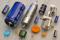
fig 2.19: capacitor
2.9 DIODES
In electronics, a diode is a two-terminal electronic component that conducts primarily in one direction (asymmetric conductance); it has low (ideally zero) resistance to the current in one direction, and high (ideally infinite) resistance in the other. A semiconductor diode, the most common type today, is a crystalline piece of semiconductor material with a p–n junction connected to two electrical terminals. A vacuum tube diode has two electrodes, a plate (anode) and a heated cathode. Semiconductor diodes were the first semiconductor electronic devices. The discovery of crystals‘ rectifying abilities was made by German physicist Ferdinand Braun in 1874. The first semiconductor diodes, called cat’s whisker diodes, developed around 1906, were made of mineral crystals such as galena. Today, most diodes are made of silicon, but other semiconductors such as selenium and germanium are sometimes used.
2.9.1 Main functions
The most common function of a diode is to allow an electric current to pass in one direction (called the diode’s forward direction), while blocking current in the opposite direction (the reverse direction). Thus, the diode can be viewed as an electronic version of a check valve. This unidirectional behaviour is called rectification, and is used to convert alternating current (AC) to direct current (DC), including extraction of modulation from radio signals in radio receivers—these diodes are forms of rectifiers.
However, diodes can have more complicated behaviour than this simple on–off action, because of their nonlinear current-voltage characteristics. Semiconductor diodes begin conducting electricity only if a certain threshold voltage or cut-in voltage is present in the forward direction (a state in which the diode is said to be forward-biased). The voltage drop across a forward-biased diode varies only a little with the current, and is a function of temperature; this effect can be used as a temperature sensor or as a voltage reference.
A semiconductor diode’s current–voltage characteristic can be tailored by selecting the semiconductor materials and the doping impurities introduced into the materials during manufacture. These techniques are used to create special-purpose diodes that perform many different functions. Diodes, both vacuum and semiconductor, can be used as shot-noise generators.
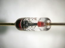
fig 2.20: diode
2.10 OPTO ISOLATOR
In electronics, an opto-isolator, also called an optocoupler, photocoupler, or optical isolator, is a component that transfers electrical signals between two isolated circuits by using light.[1] Opto-isolators prevent high voltages from affecting the system receiving the signal.[2]Commercially available opto-isolators withstand input-to-output voltages up to 10 kV[3] and voltage transients with speeds up to 10 kV/μs.[4]
A common type of opto-isolator consists of an LED and a phototransistor in the same opaque package. Other types of source-sensor combinations include LED-photodiode, LED-LASCR, and lamp–photo resistor pairs. Usually opto-isolators transfer digital (on-off) signals, but some techniques allow them to be used with analog signals.
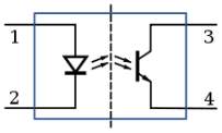
fig 2.21:circuit diagarm of opto isolator
Schematic diagram of an opto-isolator showing source of light (LED) on the left, dielectric barrier in the center, and sensor (phototransistor) on the right.
2.10.1 Operation
An opto-isolator contains a source (emitter) of light, almost always a near infrared light-emitting diode (LED), that converts electrical input signal into light, a closed optical channel (also called dielectrical channel), and a photosensor, which detects incoming light and either generates electric energy directly, or modulates electric current flowing from an external power supply. The sensor can be a photo resistor, a photodiode, a phototransistor, a silicon-controlled rectifier (SCR) or a triac. Because LEDs can sense light in addition to emitting it, construction of symmetrical, bidirectional opto-isolators is possible. An optocoupled solid state relay contains a photodiode opto-isolator which drives a power switch, usually a complementary pair of MOSFETs.
2.11 TRANSISTOR
A transistor is a semiconductor device used to amplify or switch electronic signals and electrical power. It is composed of semiconductor material usually with at least three terminals for connection to an external circuit. A voltage or current applied to one pair of the transistor’s terminals controls the current through another pair of terminals. Because the controlled (output) power can be higher than the controlling (input) power, a transistor can amplify a signal. Today, some transistors are packaged individually, but many more are found embedded in integrated circuits.
The transistor is the fundamental building block of modern electronic devices, and is ubiquitous in modern electronic systems. Julius Edgar Lilien feld patented a field-effect transistor in 1926 but it was not possible to actually construct a working device at that time. The first practically implemented device was a point-contact transistor invented in 1947 by American physicists John Bardeen, Walter Brattain, and William Shockley. The transistor revolutionized the field of electronics, and paved the way for smaller and cheaper radios, calculators, and computers, among other things. The transistor is on the list of IEEE milestones in electronics, and Bardeen, Brattain, and Shockley shared the 1956 Nobel Prize in Physics for their achievement.
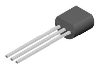
fig 2.22:transistor
2.11.1 Essential use of transistor
The essential quality of a semiconductor comes from its ability to use alittle signal applied between one try of its terminals to regulate a far larger signal at another try of terminals. This property is termed gain. It will manufacture a stronger output, a voltage or current, that is proportional to a weaker input signal; that’s, it will act as Associate in Nursing electronic equipment. as an alternative, the semiconductor will be accustomed flip current on or off {in a|during a|in Associate in Nursing exceedingly|in a very} circuit as an electrically controlled switch, wherever the quantity of current is decided by different circuit components.
There square measure 2 forms of transistors, that have slight variations in however they’re employed in a circuit. A bipolar semiconductor has terminals labeled base, collector, and electrode. alittle current at the bottom terminal (that is, flowing between the bottom and therefore the electrode) will management or switch a far larger current between the collector and emitter terminals. For a FET, the terminals square measure labeled gate, source, and drain, and a voltage at the gate will management a current between supply and drain.
The image represents a typical bipolar semiconductor in a very circuit. Charge can flow between electrode and collector terminals reckoning on the present within the base. as a result of internally the bottom and electrode connections behave sort of a junction rectifier, a free fall develops between base and electrode whereas the bottom current exists. the quantity of this voltage depends on the fabric the semiconductor is formed from, and is stated as VBE.
2.12 CONNECTOR
An electrical instrumentation, is AN electro-mechanical device accustomed be a part of electrical terminations and make AN electrical device. Electrical connectors comprises plugs (male-ended) and jacks (female-ended). The affiliation could also be temporary, as for moveable instrumentality, need a tool for assembly and removal, or function a permanent electrical joint between 2 wires or devices. AN adapter will be accustomed effectively assemble dissimilar connectors.
There are many kinds of electrical connectors. Connectors could be a part of 2 lengths of versatile copper wire or cable, or connect a wire or cable to AN electrical terminal.
In computing, AN electrical instrumentation may be called a physical interface (compare physical layer in OSI model of networking). Cable glands, called cable connectors within the America, connect wires to devices automatically instead of electrically and ar distinct from quick-disconnects acting the latter.
2.12.1 Properties
Electrical connectors ar characterized by their pin out and physical construction, size, contact resistance, insulation between pins, huskiness and resistance to vibration, resistance to entry of water or different contaminants, resistance to pressure, responsibility, period (number of connect/disconnect operations before failure), and easy connecting and disconnecting.
They may be keyed to forestall insertion within the wrong orientation, connecting the incorrect pins to every different, and have protection mechanisms to make sure that they’re totally inserted and can’t work loose or fall out. Some connectors ar designed specified bound pins build contact before others once inserted, and break initial on disconnection; this protects circuits generally in connectors that apply power, e.g. connecting safety ground initial, and sequencing connections properly in hot swapping applications.
It is typically fascinating for a instrumentation to be simple to spot visually, fast to assemble, need solely easy tooling, and be cheap. In some cases AN instrumentation manufacturer would possibly select a instrumentation specifically as a result of it’s not compatible with those from different sources, permitting management of what could also be connected. No single instrumentation has all the perfect properties; the proliferation of varieties may be a reflection of differing necessitiesFretting may be a common failure mode in electrical connectors that haven’t been specifically designed to forestall it.
CHAPTER 3 - SOFTWARE
AT commands ar directions wont to management a electronic equipment. AT is that the abbreviation of attention. each statement starts with “AT” or “at”. that is why electronic equipment commands ar referred to as AT commands. several of the commands that ar wont to management wired dial-up modems, like ATD (Dial), ATA (Answer), ATH (Hook control) and ATO (Return to on-line knowledge state), are supported by GSM/GPRS modems and mobile phones. Besides this common AT command set, GSM/GPRS modems associate degreed mobile phones support an AT command set that’s specific to the GSM technology, which has SMS-related commands like AT+CMGS (Send SMS message), AT+CMSS (Send SMS message from storage), AT+CMGL (List SMS messages) and AT+CMGR (Read SMS messages).
Basic Commands and Extended Commands
There area unit 2 sorts of AT commands: basic commands and extended commands.
Basic commands area unit AT commands that don’t begin with “+”. for instance, D (Dial), A (Answer), H (Hook control) and O (Return to on-line knowledge state) area unit basic commands.
Extended commands area unit AT commands that begin with “+”. All GSM AT commands area unit extended commands. for instance, +CMGS (Send SMS message), +CMSS (Send SMS message from storage), +CMGL (List SMS messages) and +CMGR (Read SMS messages) area unit extended commands.
3.1 Software Architecture
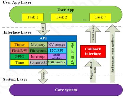
fig:3.1:software architecture
3.2 SIM card interface
AT commands
AT commands ar wont to management electronic equipment. AT is that the abbreviation for attention. A instruction could be a string of characters sent from an information terminal instrumentality to the electronic equipment whereas the command is during a command state. A instruction contains a prefix, a body and a eradicator. every instruction should begin with the character sequence AT and should be terminated by a printing operation. Commands entered in grapheme or minuscule is accepted, however each the A and T should be of constant case, i.e., “AT or “at.
The default eradicator is that the ENTER key
The basic commands consists of single code characters, or single characters proceed by a prefix character (e.g., “&” or “+”), followed by a decimal parameter. Missing decimal parameters ar evaluated as zero.
3.2.1 General commands
Check the manufacturer: +CGMI
| Description | Check the manufacturer information |
| Format | AT+CGMI |
| Syntax | NULL |
| Response |
Or +CME ERROR: |
table3.1:command for manufacturing information
Query Module Model: +CGMM
| Description | Query Module Model |
| Format | AT+CGMM |
| Syntax | NULL |
| Response |
or+CME ERROR: |
table 3.2:command for query module
Query version :+CGMR
| Description | Query Version |
| Format | AT+CGMR |
| Syntax | NULL |
| Response |
Or +CME ERROR: |
table 3.3:command for query version
Get Sequence Number:+CGSN
| Description | This command is to get sequence number, known as IMEI (International Mobile Equipment Identity)
|
| Format | AT+CGSN |
| Syntax | Null |
| Response |
Or CME ERROR: |
table3.4:command for sequence number
power on : +CGPON
| Description | This command is to get the message as power on |
| Format | AT+CGPON |
| Syntax | Null |
| Response |
Or CME ERROR: |
table3.5:command for power on
power off :+CGPOF
| Description | This command is to get the message as power off |
| Format | AT+CGPOF |
| Syntax | Null |
| Response |
Or CME ERROR: |
table3.6:command for power off
TO start a motor:+CGDSAS
| Description | This command is to get the message as device started successfully |
| Format | AT+CGDSAS |
| Syntax | Null |
| Response |
Or CME ERROR: |
table3.7:command to switch on motor
To stop a motor:+CGDSPS
| Description | This command is to get the message as device stopped successfully |
| Format | AT+CGDSPS |
| Syntax | Null |
| Response |
Or CME ERROR: |
table3.8:command to switch off motor
3.2.2 Description of AT commands
AT: “AT” is sent t o the GSM/GPRS modem to test the connection. The GSM/GPRS modem sends back the result code “OK”, which means the connection between the HyperTerminal program and the GSM/GPRS modem works fine.
AT +CMGF is used to instruct the GSM/GPRS modem to operate in SMS text mode. The result code “OK” is returned, which indicates the command line “AT+CMGF=1” has been executed successfully.
AT +CMGW is used to write an SMS text message to the message storage of the GSM/GPRS modem. “+919848030448” is the recipient mobile phone number. After typing the recipient mobile phone number, you should press the enter button of the keyboard.
The GSM/GPRS modem will then return a prompt “>” and you can start typing the SMS text message “A simple demo of SMS text messaging.
“AT+CMGW: 1” tells us that the index assigned to the SMS text message is 1. It indicates the location of the SMS text message in the message storage.
AT +CMSS is used to send the SMS text message from the message storage of the GSM/GPRS modem. “1” is the index of the SMS text message.
The result code “OK” indicates the execution of the AT command AT +CMSS are successful.
CHAPTER 4 - IMPLEMENTATION
4.1 Hardware Implementation
4.1.1 Block Diagram
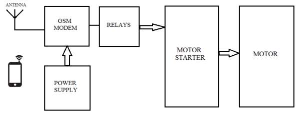
fig4.1:block diagram
Our block diagram gives the clear idea of how our components are connected on the PCB. The power supply is given to the GSM modem which has the connection to the antenna to receive the signals from the cell phone, then the modem is connected to the relays to operate them electrically from distance. By using the connectors the connection is made from relays to the motor starter, which starts the motor. We also use opto isolators to isolate inputs from outputs using light energy to electric energy. The motor starter is directly connected to motor and it is responsible to switch ON and OFF the motor.
4.1.2 Circuit diagram
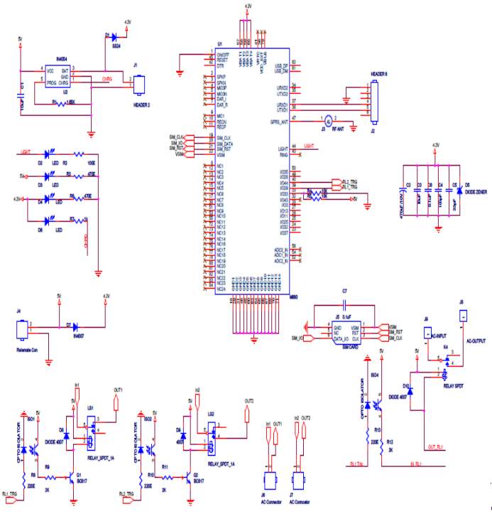
fig4.2:circuit diagram
4.1.3 PCB Layout
A computer circuit board (PCB) automatically supports and electrically connects electronic parts mistreatment semiconductive tracks, pads and alternative options engraved from copper sheets laminated onto a non-conductive substrate. computer circuit boards area unit utilized in virtually the only electronic merchandise.
Printed circuit board design generation was at the start a completely manual method done on clear sheets at a scale of typically two or four times the specified size.
DESIGN MANUFACTURING
1. Patterning
In reductive ways the unwanted copper is removed to go away solely the required copper pattern. .
Direct optical device imaging techniques area unit typically used for high-resolution necessities.
In reductive ways the unwanted copper is removed to go away solely the required copper pattern. In additive ways the pattern iselectroplated onto a blank substrate employing a complicated method.
The pattern within the manufacturer’s PCB CAM system is sometimes output on a photograph mask (photo-tool, film) by a icon plotter and replicated via screen printing or by exposing on a icon-sensitive photo resist coating. Direct optical device imaging techniques area unit typically used for high-resolution necessities.
Additive processes adds desired copper traces to associate degree insulating substrate.
In the full additive method the blank laminate is roofed with a light-sensitive film that is imaged (exposed to light-weight although a mask and so developed that removes the unexposed film).
2. Drilling
Holes through a PCB square measure usually trained with small-diameter
It is additionally potential with controlled-depth drilling, optical device drilling, or by pre-drilling the individual sheets of the PCB
3. Assembly
In surface-mount construction, the parts area unit placed on pads or lands on the outer surfaces of the PCB
4. Copper thickness
Copper thickness of PCBs may be such as units of length (in micrometers or mils) however is commonly such as weight of copper per space (in ounce per sq. foot) that is simpler to live.
LAYOUT
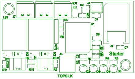
fig4.3:topsilk layout
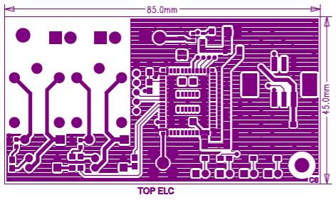
fig4.4:top elc layout
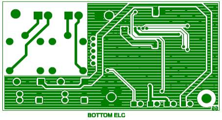
fig4.5:bottom elc layout
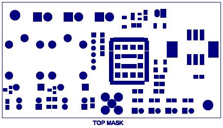
fig4.6:top mask layout
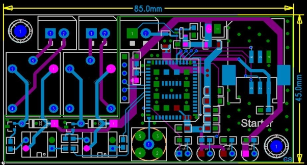
fig4.7:pcb layout
4.2 Software Implementation
4.2.1 The Procedure for Sending AT Commands to a Mobile Phone or GSM/GPRS Modem Using MS HyperTerminal
- Put a sound SIM card into the portable or GSM/GPRS electronic equipment. you’ll acquire a SIM card by subscribing to the GSM service of a wireless network operator.
- Connect your portable or GSM/GPRS electronic equipment to a pc and found out the corresponding wireless electronic equipment driver. you must notice the wireless electronic equipment driver within the CD or disk that was provided by the manufacturer. If the manufacturer doesn’t offer such CD or disk along with your portable or GSM/GPRS electronic equipment, you’ll attend the manufacturer’s computing machine and see whether or not the wireless electronic equipment driver are often downloaded there. If the wireless electronic equipment driver can’t be found on the net website, you’ll still use Windows’ customary electronic equipment driver.
- Run MS HyperTerminal by choosing begin ->Programs ->Accessories -> Communications ->HyperTerminal.
- In the affiliation Description panel, enter a reputation associate degree select an icon you wish for the affiliation. Then click the OK button.
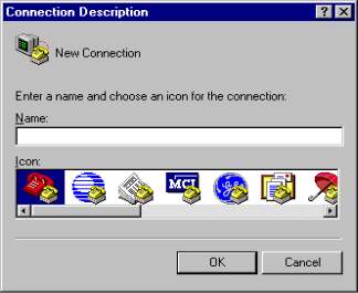
fig4.8:step 1
In the hook up with panel, opt for the COM port that your movable or GSM/GPRS electronic equipment is connecting to within the Connect mistreatment dance orchestra box. as an example, opt for COM1 if your movable or GSM/GPRS electronic equipment is connecting to the COM1 port .Then click the ok button(Sometimes there’ll have over one COM port within the Connect mistreatment dance orchestra box. to understand that COM port is employed by your mobile
In windows98: attend board -> Phone and electronic equipment choices. Then click the Modems tab. within the list box, you’ll see that COM port the movable or GSM/GPRS electronic equipment is connected to.
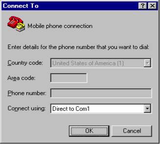
fig4.9:step 2
The Properties panel comes out. Enter the right port settings for your portable or GSM/GPRS electronic equipment. Then click the OK button.
To find the right port settings that ought to be used along with your portable or GSM/GPRS electronic equipment, a way is to consult the manual of your portable or GSM/GPRS electronic equipment. in our own way is to visualize the port settings employed by the wireless electronic equipment driver that you just put in earlier.
To check the port settings employed by the wireless electronic equipment driver on Windows ninety eight, follow thisa. visit control board -> electronic equipment.b. choose your portable or GSM/GPRS electronic equipment within the list box.c. Click the Properties button.d. The Properties panel seems. the most speeds field on the final tab corresponds to HyperTerminal’s Bits per second field. Click the affiliation tab and you’ll be able to realize the settings for knowledge bits, parity and stop bits. Click the Advanced button and you’ll be able to realize the setting for flow management.
To check the port settings employed by the wireless electronic equipment driver on Windows 2000 and Windows XP, follow these steps:a. visit control board -> Phone and electronic equipment choices -> Modems tab.b. choose your portable or GSM/GPRS electronic equipment within the list box.c. Click the Properties button.d. The Properties panel seems. Click the Advanced tab and so click the amendment Default Preferences button.e. The amendment Default Preferences panel seems. The Port speed field on the final tab corresponds to HyperTerminal’s Bits per second field. you’ll be able to conjointly realize the setting for flow management on the final tab. On the Advanced tab, you’ll be able to realize the settings for knowledge bits, parity and stop bits.)
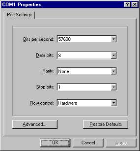
fig4.10:step 3
Type “AT” within the main window. A response “OK” ought to be came from the transportable or GSM/GPRS electronic equipment. sort “AT+CPIN?” within the main window. The AT command “AT+CPIN?” is employed to question whether or not the transportable or GSM/GPRS electronic equipment is looking ahead to a PIN (personal number, i.e. password). If the response is “+CPIN: READY”, it suggests that the SIM card doesn’t need a PIN and it’s prepared to be used. If your SIM card needs a PIN, you would like to line the PIN with the AT command “AT+CPIN=
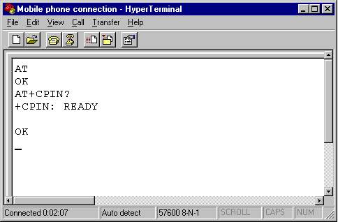
fig4.11:step 4
If you get the responses higher than, your portable or GSM/GPRS electronic equipment is functioning properly. you’ll be able to begin typewriting your own AT commands to manage the portable or GSM/GPRS electronic equipment.
4.2.2 Command prompt
A prompt, conjointly stated merely as a prompt, may be a short text message at the beginning of the command on a command interface. A command interface (CLI) is associate all-text show mode that’s provided in a very console or terminal window by a shell. A console is associate all-text show mode that occupies the complete show monitor screen.
A terminal window may be a text-only window that emulates a console and which might be opened on a GUI (graphical user interface) screen. A shell may be a program that not solely provides the command interface for software however conjointly executes (i.e., runs) commands that square measure typewritten into it. The command is that the line on that commands square measure typewritten in a very console or terminal window. A command is associate instruction to inform a laptop to try and do one thing, e.g., to execute a program.
The functions of a prompt square measure
(1) to tell the user that the system is prepared for future command, information component or different input and
(2) to assist the user set up and execute resultant operations. Prompts square measure found on the command interface of any software that gives a command line interface. This includes not solely Unix-like operative systems however conjointly MS-DOS and therefore the numerous Microsoft Windows systems. The contents of the prompt amendment in step with many factors, as well as the software, the precise shell or different text-mode program getting used and individual user settings.
4.2.3 Program
Source code A
#include “neoway_openplatform.h”
#include “all.h”
char DeviceStat=0;
void analyze_ph_no(void )
{
char phnn[11];
NeowayModuleTypeEnum mod_id;
Neoway_UartSend(0,” i am in analyze_ph_no”,strlen(“ i am in analyze_ph_no”));
if(memcmp(&owner1[3],Ph_no,10)==0 || memcmp(&owner2[3],Ph_no,10)==0)
{
_Printf(“ Ph no matched now trying to change the state “);
Neoway_StartTimer(&neoway_timer_task6,216);//
}
/*
if(AdminData.RegFlag[0]==’0′)
{
Neoway_UartSend(0,” reg flag is zero”,strlen(“ reg flag is zero”));
AdminData.RegFlag[0]=’1′;
strcpy(AdminData.Admin,Ph_no);
Neoway_SendMsgTask(mod_id,NEOWAY_MOD_USER3,Flash_ID,NULL,0);//
}
*/
}
Source code B
#ifndef __NEOWAY_TYPE_H__
#define __NEOWAY_TYPE_H__
#ifndef FALSE
#define FALSE 0
#endif
#ifndef TRUE
#define TRUE 1
#endif
#ifndef NULL
#define NULL ((void *) 0)
#endif
/****************************************************************************
* Type Definitions
***************************************************************************/
typedef unsigned char bool;
typedef unsigned char BOOL;
typedef unsigned char U8;
typedef signed char S8;
typedef unsigned short U16;
typedef short S16;
typedef unsigned int U32;
typedef int S32;
typedef unsigned long long U64;
/* portable 8-bit unsigned integer */
typedef unsigned char kal_uint8;
/* portable 8-bit signed integer */
typedef signed char kal_int8;
/* portable 16-bit unsigned integer */
typedef unsigned short int kal_uint16;
/* portable 16-bit signed integer */
typedef signed short int kal_int16;
/* portable 32-bit unsigned integer */
typedef unsigned int kal_uint32;
/* portable 32-bit signed integer */
Main
#include “neoway_openplatform.h”
#include “all.h”
void print_info(void);
unsigned char AdminDataBuf[512];
StartData AdminData;
MessageData Message;
void write_config(void);
void SetSmsParameters(S8 *phno,S8 *information)
{
int i=0;
unsigned char ctrlz[1]=0x1a;
NeowayModuleTypeEnum mod_id;
MessageData test;
memset(&Message,’�′,sizeof(Message));
strcpy(test.Data,information);
strcat(test.Data,ctrlz);
strcpy(test.Phno,”AT+CMGS=””);
strcat(test.Phno,phno);
strcat(test.Phno,”””);
strcat(test.Phno,”�″);
strcpy(Message.Phno,test.Phno);
strcpy(Message.Data,test.Data);
_Printf(“ Message Data in SetSMSParameters : %s”,information);
_Printf(“ Message phno is : %s”,Message.Phno);
_Printf(“ Message Data is : %s”,Message.Data);
_Printf(“ assining smsid :”);
Neoway_SendMsgTask(NEOWAY_MOD_USER3,NEOWAY_MOD_USER3,Send_Msg_ID,NULL,0);//
_Printf(“ assining smsid completed :”);
}
void Start_FactoryReset(void)
{
U8 davis_default[10]={27,12,14,0,1,0,0,0,0};
char i=0;
Printf(“ i am in factory reset”,strlen(“ i am in factory reset”));
memset(AdminDataBuf,0,512);
memset(&AdminData,0,sizeof(AdminData));
strcpy(AdminData.RegFlag,”0″);
strcpy(AdminData.SimSer,”01234567890123456789″);
strcpy(AdminData.Admin,”9440430199″);
strcpy(AdminData.User1,”0123456789″);
strcpy(AdminData.User2,”0123456789″);
strcpy(AdminData.User3,”0123456789″);
strcpy(AdminData.User4,”0123456789″);
strcpy(AdminData.User5,”0123456789″);
AdminData.UserCount=0;
for(i=0;i
AdminData.Time_Count_Davis[i]=davis_default[i];
strcpy(AdminData.Apn,”AIRTELGPRS.COM”);
strcpy(AdminData.Ip,”49.206.0.170″);
strcpy(AdminData.Port,”1500″);
strcpy(AdminData.ATIP,”182.18.161.10″);
strcpy(AdminData.ATPort,”8000″);
strcpy(AdminData.AFIP,”49.206.0.170″);
strcpy(AdminData.AFPort,”21″);
strcpy(AdminData.GSMVer,”1.01″);
strcpy(AdminData.MCUVer,”0.00″);
strcpy(AdminData.SimSerFlag,”0″);
write_config();
}
void Start_FactoryInit(void)
{
Printf(“ i am in factory init”,strlen(“ i am in factory init”));
memset(AdminDataBuf,0,512);
Neoway_GetNvParam(AdminDataBuf);
memcpy(&AdminData,AdminDataBuf,sizeof(AdminData));
if (AdminData.RegFlag[0] != ‘1’)
Start_FactoryReset();
ReadConfig();
}
void ReadConfig(void)
{
short int debug=1;
NeowayModuleTypeEnum mod_id;
memset(&Message,’�′,sizeof(Message));
_Printf(“ i am in factory read”,strlen(“ i am in factory read”));
print_info();
memset(AdminDataBuf,0,512);
Neoway_GetNvParam(AdminDataBuf);
memcpy(&AdminData,AdminDataBuf,sizeof(AdminData));
if(SendSmsFlag)
{
/ strcpy(Message.Phno,”AT+CMGS=””);
strcat(Message.Phno,AdminData.Admin);
strcat(Message.Phno,”” ”);
strcat(Message.Phno,”�″);
strcpy(Message.Data,”Admin Registered Sucessfully”);
Neoway_SendMsgTask(NEOWAY_MOD_USER3,NEOWAY_MOD_USER3,Send_Msg_ID,NULL,0);//
*/
SetSmsParameters(AdminData.Admin,”Admin Registered Successfully”);
}
//AT+NETAPN=”TATA.DOCOMO.INTERNET”,””,””
strcpy(TcpIpPort,”AT+TCPSETUP=1,”);
strcat(TcpIpPort,AdminData.Ip);
strcat(TcpIpPort,”,”);
strcat(TcpIpPort,AdminData.Port);
strcat(TcpIpPort,” ”);
strcpy(AmpTcpIpPort,”AT+TCPSETUP=2,”);
strcat(AmpTcpIpPort,AdminData.ATIP);
strcat(AmpTcpIpPort,”,”);
strcat(AmpTcpIpPort,AdminData.ATPort);
strcat(AmpTcpIpPort,” ”);
strcpy(AmpFtpIpPort,”AT+FTPLOGIN=”);
strcat(AmpFtpIpPort,AdminData.AFIP);
strcat(AmpFtpIpPort,”,”);
strcat(AmpFtpIpPort,AdminData.AFPort);
strcat(AmpFtpIpPort,”,”);
strcat(AmpFtpIpPort,”amp-linux”);
strcat(AmpFtpIpPort,”,”);
strcat(AmpFtpIpPort,”amptronics”);
strcat(AmpFtpIpPort,” ”);
//AT+FTPLOGIN=49.206.0.170,21,amp-linux,
strcpy(APN,”AT+NETAPN=””);
strcat(APN,AdminData.Apn);
strcat(APN,””,””,”””);
strcat(APN,” ”);
}
void write_config(void)
{
short int debug=1;
_Printf(“ i am in factory write”,strlen(“ i am in factory write”));
memcpy(AdminDataBuf,&AdminData,sizeof(AdminData));
Neoway_SaveNvParam(AdminDataBuf);
}
void print_info(void)
{
char AmpMessage[300];
int i=0;
_Printf(“ SimSer : %s”,AdminData.SimSer);
_Printf(“ SimSerFlag : %s”,AdminData.SimSerFlag);
_Printf(“ Admin : %s”,AdminData.Admin);
_Printf(“ User1 : %s”,AdminData.User1);
_Printf(“ User2 : %s”,AdminData.User2);
_Printf(“ User3 : %s”,AdminData.User3);
_Printf(“ User4 : %s”,AdminData.User4);
_Printf(“ User5 : %s”,AdminData.User5);
_Printf(“ RegFlag : %s”,AdminData.RegFlag);
_Printf(“ UserCOunt : %d”,AdminData.UserCount);
_Printf(“ Automatic mode : %s”,AdminData.AutoMode);
_Printf(“ intelligent mode: %s”,AdminData.IntlgMode);
_Printf(“ Normal mode : %s”,AdminData.NormalMode);
_Printf(“ AdcLowCutof : %s”,AdminData.AdcLowCutof);
_Printf(“ AdcLowCutofs : %s”,AdminData.AdcHighCutof);
_Printf(“ DND Stat : %s”,AdminData.DndStat);
for(i=0;i
{
_Printf(“ config data [%d] :%d “,i,AdminData.Time_Count_Davis[i]);
} strcpy(AmpMessage,” AMB:”);strcat(AmpMessage,AdminData.Admin);
strcat(AmpMessage,” ATI:”);strcat(AmpMessage,AdminData.ATIP);
strcat(AmpMessage,” ATP:”);strcat(AmpMessage,AdminData.ATPort);
strcat(AmpMessage,” AFI:”);strcat(AmpMessage,AdminData.AFIP);
strcat(AmpMessage,” AFP:”);strcat(AmpMessage,AdminData.AFPort);
strcat(AmpMessage,” AGV:”);strcat(AmpMessage,AdminData.GSMVer);
strcat(AmpMessage,” AMV:”);strcat(AmpMessage,AdminData.MCUVer);
strcat(AmpMessage,” NIP:”);strcat(AmpMessage,AdminData.Ip);
strcat(AmpMessage,” NP0:”);strcat(AmpMessage,AdminData.Port);
strcat(AmpMessage,” NIM:”);strcat(AmpMessage,gNeo_imei_str);
strcat(AmpMessage,”�″);
_Printf(“ AmpMessage len : %d “,strlen(AmpMessage));
_Printf(“ AmpMessage: %s “,AmpMessage);
/*
if(memcmp(AdminData.SimSer,”0123456789”,10)==0)
_Printf(“ sim valid”);
if(memcmp(AdminData.Admin,”0123456789″,10)==0)
_Printf(“ Admin valid”);
if(memcmp(AdminData.User1,”0123456789″,10)==0)
_Printf(“ user1 valid”);
if(memcmp(AdminData.User2,”0123456789″,10)==0)
_Printf(“ user2 valid”);
if(memcmp(AdminData.User3,”0123456789″,10)==0)
_Printf(“ user3 valid”);
if(memcmp(AdminData.User4,”0123456789″,10)==0)
_Printf(“ user4 valid”);
if(memcmp(AdminData.User5,”0123456789″,10)==0)
_Printf(“ user5 valid”);
*/
}
strcpy(Message.Phno,”AT+CMPON=””);
strcat(Message.Phno,AdminData.Admin);
strcat(Message.Phno,”” ”);
strcat(Message.Phno,”�″);
strcpy(Message.Data,”Power On”);
strcpy(Message.Phno,”AT+CMPOF=””);
strcat(Message.Phno,AdminData.Admin);
strcat(Message.Phno,”” ”);
strcat(Message.Phno,”�″);
strcpy(Message.Data,”Power off”);
strcpy(Message.Phno,”AT+CMDSAS=””);
strcat(Message.Phno,AdminData.Admin);
strcat(Message.Phno,”” ”);
strcat(Message.Phno,”�″);
strcpy(Message.Data,”Device started Sucessfully”);
strcpy(Message.Phno,”AT+CMDSPS=””);
strcat(Message.Phno,AdminData.Admin);
strcat(Message.Phno,”” ”);
strcat(Message.Phno,”�″);
strcpy(Message.Data,”Device stopped Sucessfully”);
void print_info(void)
{
char AmpMessage[300];
int i=0;
_Printf(“ SimSer : %s”,AdminData.SimSer);
_Printf(“ SimSerFlag : %s”,AdminData.SimSerFlag);
_Printf(“ Admin : %s”,AdminData.Admin);
_Printf(“ User1 : %s”,AdminData.User1);
_Printf(“ User2 : %s”,AdminData.User2);
_Printf(“ User3 : %s”,AdminData.User3);
_Printf(“ User4 : %s”,AdminData.User4);
_Printf(“ User5 : %s”,AdminData.User5);
//AT+FTPLOGIN=49.206.0.170,21,amp-linux,
CHAPTER 5 - RESULT
Based on the commands given to the Neoway M680 GSM modem, when we switch ON the power the base number will get the SMS (”POWER ON”), similarly when the power is off ,the SMS is received(”POWER OFF”) .
To switch ON a motor a call is established from the base number, the motor gets on after three rings and will be receiving a message saying “Device started successfully” and the same procedure is followed to switch OFF the motor and will be receiving a message saying “Device stopped successfully”
Only a few registered numbers can operate the motor and only the base number can add other users.
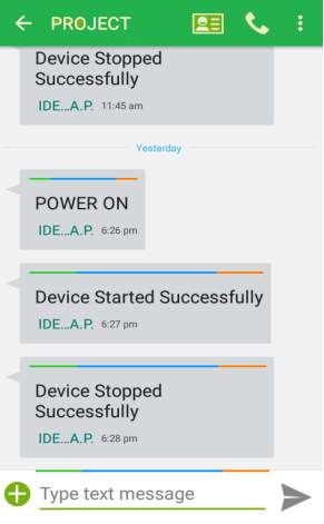
fig5.1:result
The block diagram of the system is shown. The missed calls are received from the user mobile to perform specific task. Based on the received signals from the mobile phone, the signals are sent to the GSM module to switch on/off the motor through the starter using the relays. The relay is controlled by the port.
The GSM modem communicates with the user cell phone to intimate the condition obtained for the microcontroller. Serial Port Adapter works in data and AT modes and needs to be properly configured. During power-on condition, SPA is initially in data mode and by sending characters within 3 seconds, the device is moved into AT mode for configuration. In AT mode, series of commands are sent for proper configuration. If match is found, it starts data communication between micro-controller system and GSM. AT commands are sent by sending text strings ‘A’, ‘T’, along with specified command strings through serial port to cell phone and are executed on receipt of carriage return. The result codes are sent by cell phone to system to indicate the status after execution of command.
The operational cost of communication between user and GSM is further reduced by using concept of miscall where in no charges are incurred by using only ring signal for information transfer. A voice call is treated as miscall when either calling party disconnects after receiving ring tones or called party does not respond to call within specified time.
CHAPTER 6 - CONCLUSION
Design such a project and implement it, we tend to gather nice sensible expertise. we tend to tried to implement our theoretical information with success. This course teaches us regarding the way distinction between theoretical and sensible information. This project will increase our ability to figure as a gaggle and it helps US in future life. However we tend to face many issues as a result of inconvenience of quality merchandise, technical support and ignorance. Despite that we tend to enjoyed our work greatly and with success finished that job in perfection. In this dynamic world motor is that the most convenient and great tool in trade. massive rated motor needed versatile management and protection. we tend to hope our project will bring dynamic modification in our industrial level motor dominant system. The system is designed to have cell phone with inbuilt security against unauthorized users. Any cell phone model can be used for communication so that the system improves its adaptability to use. Low operating cost using messages and missed calls are the major attractions of this system.
GSM in this particular system provides numerous advantages over methods that have been previously used. Data transmission is charged at standard SMS rates, thus the charges are not based on the duration of data transmission. The cost efficient transmission of readings ensures that power consumption values can be transmitted more frequently to a remote station. The implications of being able to transmit readings more often are that energy utilities will be able to generate timely bills, better understand energy demand patterns, manage meter failures more efficiently and manage fraud better.
6.1 Future scope
This project has a huge future scope. Now a day’s GSM is being used in various applications. So as the result, the demand on GSM will go on ever increasing in engineering domain and wireless communications. As the domain of communication has broad opportunities of research and development, GSM will always required and taken into account for research and development. In future, we can design, the global system for mobile communication with even greater efficiency and flexibility. We can also implement more base SIMs to the modem and can explore it.
The future enhancement of this work is to develop the system to help illiterate farmers using spoken commands [8-9]. The spoken commands are recognized and converted into text message for SMS which helps them to identify the faults and commands easily. Moreover, in cases where non-deterministic response of SMS is not acceptable, dedicated voice based call approach can be incorporated. With introduction of MMS message support, it is possible to capture images from field using higher end cell phone and disease-pest control management can be carried out by analysis of these images by agriculturists Various parameters such as temperature, humidity, water level etc., can be noted at regular intervals on daily basis and time duration of pump, amount and type of fertilizers, pesticides, etc., can be decided based on analysis of acquired data. It is expected that technological assistance to farmers can tremendously boost the productivity of food grains and bring prosperity to this hardworking population
6.2 References
[1] https://webcache.googleusercontent.com/search?q=cache:r7UZxetMkZoJ:https://www.engineersgarage.com/articles/gsm-gprs-modules+&cd=1&hl=en&ct=clnk&gl=in
[2] http://webcache.googleusercontent.com/search?q=cache:32YJzlzgeZIJ:www.neoway.com/en/product/detail.aspx%3Fid%3D100000016246878%26nodecode%3D105010001+&cd=1&hl=en&ct=clnk&gl=in
[3] https://www.google.co.in/?gfe_rd=cr&ei=ivX5WOeFCZWDoAOksqyYAQ#q=related:https://www.elprocus.com/gsm-architecture-features-working/+gsm+module
[4] https://www.google.co.in/?gfe_rd=cr&ei=ivX5WOeFCZWDoAOksqyYAQ#q=related:https://www.researchgate.net/file.PostFileLoader.html?id%3D53b26743d5a3f2c1768b4574%26assetKey%3DAS%253A273645832736795%25401442253658928+gsm+module
[5] https://www.google.co.in/?gfe_rd=cr&ei=ivX5WOeFCZWDoAOksqyYAQ#q=related:www.ijoart.org/docs/GSM-Based-Automatic-Motor-Control-and-Protection-System.pdf+gsm+based+automatic+motor+control+and+protection+system
[6] https://www.google.co.in/?gfe_rd=cr&ei=ivX5WOeFCZWDoAOksqyYAQ#q=https://www.codeproject.com/articles/38705/send-and-read-sms-through-a-gsm-modem-using-at-com
[7] https://www.google.co.in/?gfe_rd=cr&ei=ivX5WOeFCZWDoAOksqyYAQ#q=related:www.wless.ru/files/GSM/Neoway/Neoway_M680_AT_Command_Set_V1_0.pdf+http://www.wless.ru/files/GSM/Neoway/Neoway_M680_AT_Command_Set_V1_0.pdf
[8] https://webcache.googleusercontent.com/search?q=cache:-Eer3M-Vhw4J:https://www.ijareeie.com/upload/2016/ncrte/4_EIE04.pdf+&cd=5&hl=en&ct=clnk&gl=in
[9] https://www.google.co.in/?gfe_rd=cr&ei=bvz5WNe4B86FoAPJkYa4Cg#q=related:www.developershome.com/sms/howToUseHyperTerminal.asp+http://www.developershome.com/sms/howToUseHyperTerminal.asp
[10] https://www.google.co.in/search?q=voltage+regulator&source=lnms&sa=X&ved=0ahUKEwiUz6qjw7jTAhVEOo8KHSnhDh4Q_AUIBSgA&biw=1366&bih=700&dpr=1#q=related:www.projectsof8051.com/sms-based-device-control-using-gsm-modem/+gsm+based+motor+control+project+report
[11] https://webcache.googleusercontent.com/search?q=cache:Pvrd_WT7sCMJ:https://www.lifewire.com/power-supply-unit-2618158+&cd=17&hl=en&ct=clnk&gl=in
[12] related:www.leedsbeckett.ac.uk/inn/alic/agorra/2_Chapter2_LiteratureReview.pdf literature review on gsm based control system
[13] related:shodhganga.inflibnet.ac.in/bitstream/10603/5394/5/05_chapter2.pdf literature review on gsm based control system
[14] Jain Sarthak,Vaibhav Anant and Goyal Lovely ,“Raspberry Pi based Interactive Home Automation System through E-mail.”,IEEE transaction,2014 International Conference on Reliability, Optimization and Information Technology ICROIT 2014, India, Feb 6- 8 2014
[15] Mahesh.N.Jivani, “GSM Based Home Automation System Using App-Inventor for Android Mobile Phone”, 2014, International Journal of Advanced Research in Electrical, Electronics and Instrumentation Engineering, Vol. 3(9), pp. 12121-12128.
[16] ETSI TS 127 007 V5.3.0 (2003-03) Digital cellular telecomm. System, Universal Mobile Telecommunications System (UMTS); AT command set for 3G User Equipment (UE) (3GPP TS 27.007 version 5.3.0 Release 5, available online: http://www.etsi.org.
Cite This Work
To export a reference to this article please select a referencing stye below:
Related Services
View all


Related Content
All TagsContent relating to: "Technology"
Technology can be described as the use of scientific and advanced knowledge to meet the requirements of humans. Technology is continuously developing, and is used in almost all aspects of life.
Related Articles

DMCA / Removal Request
If you are the original writer of this dissertation and no longer wish to have your work published on the UKDiss.com website then please: