Human Body Musculoskeletal Mechanics for Hip Prosthesis
Info: 7716 words (31 pages) Dissertation
Published: 9th Dec 2019
Tagged: PhysiologyMedicinePhysiotherapy
History and Background
Biomechanics is a discipline which applies engineering principles to biological systems and medical problems. Its fields of application include but are not limited to orthopaedic and cardiovascular surgery, traumatology, dentistry, rehabilitation [26]. Biomechanics overlaps with basic medical sciences such as anatomy and biomaterials. It can be placed under the umbrella term or biomedical engineering (or bioengineering) but it is truly a branch of biomechanical engineering considering that engineering mechanics is one basic science of mechanical engineering.
After World War II, there was a massive increase in biomechanics activities [25]. This development of biomechanics activities was triggered by two events: firstly, the development of computers and technology, and secondly the emphasis put on close surgical reconstruction of body functions in the disabled and the elderly. As a result, complex mechanical behaviour of biological tissues and structures can now be realistically modelled and successfully analysed.
Augmentation in the routine application of artificial joints and new fracture fixation devices of orthopaedic surgery is an ideal example. However, long-term success of the devices depends on a solid understanding of human body musculoskeletal mechanics.
Definition of Forces
The aim of this section is to discuss the aspects that are important when it comes to the identification and evaluation of forces of human body parts.
The forces in the musculoskeletal system are due to gravity, muscle action, acceleration and deceleration of body parts and any restraints of on joints.
The study of forces and motions between rigid bodies in referred to in mechanical engineering as kinetics.
When rigid bodies are at rest or moving at a constant speed, they are said to be static. At this point in time, all external forces actin on the structure are in equilibrium with each other. The study of bodies in this condition is called statics. The principles of statics follow Newtonian laws. [EXPLAIN NEWTONIAN LAWS]
Stressed and Strains
Materials deform when subjected to loading. Although deformation may not actually be visible to the naked eye, it is present in most cases. Molecules resist deformation through mutual bonds that generate a number of internal forces.
Solid mechanics is a sub branch of mechanical engineering which centres its focus on studying the deformational behaviour of materials as they are put under certain loads. Local deformations are represented by strain, whilst stress represent the internal forces generated within the material.
A structural analysis is an investigation of the stressed and strain that occur in rigid structures. These analyses often include an application of the principles of the continuum theory.
Although structure materials are not actually continuous at a molecular level or even at a microscopic level, the mechanical behaviour of structure can usually be described and predicted to a reasonable degree of accuracy with methods that neglect discontinuities on a much smaller scale. Within the frame of the continuum theory, the materials are regarded as indeterminately divisible and therefore, variable such as stresses and strains can be defined in an indefinitely small point. This assumption of the material is sometimes quite adequate, as in metals, and sometimes rather rough in materials such as trabecular bone.
Strain is relative. This is because it represents a change in dimension relative to the original dimension of the material before it is put under a load. On the other hand, stress is defined scientifically as the result of a specific amount of force per unit area. Both of these forces occur as local phenomena.
The stress state in a point of a structure during a two dimensional static structural analysis is characterized by three components; either a combination of the magnitudes of two direct stresses and one shear stress component, or by the magnitudes of two principle stress components and the principle stress orientation.
Compressive and tensile stress are both direct stresses with only the negative and positive sign to differentiate the two, respectively. Mathematically, the two are treated as the same variable, however, practically their influences on materials can differ.
While two dimensional stress states are characterized by three stress components, a three dimensional stress state is characterized by six stress components instead; the magnitudes of the three direct stresses and a set of three shear stress components. Needless to say, in reality, all structures are in fact three dimensional, but the stress states of three dimensional structures can be adequately represents by a two dimensional approximation. The strain and stress states in a point of a structure are related to each other through the elastic mechanical properties of the material being regarded.
Statics of the lower extremity
The hip joint is considered as an ideal spherical joint. This implies three degrees of freedom for rotation and hence the three main axes for abduction-adduction, extension-flexion and finally internal-external rotational movements. The joint is restrained by neighbouring bones in such a way that there is virtually no degree of freedom for translation.
Introduction
The life span of a hip prosthesis is expected to be at least around 15 to 20 years.
One of the main problems for THA patients during their daily activities is the risk of dislocation. Dislocation requires the primary THA to be revised in order to avoid major complications to the patient’s health. There are two main types of dislocation which are discussed in this study; early dislocation and late dislocation. Early dislocation is the result of impingement of the femoral neck from the acetabular cup lip due to a limited range of motion. Late dislocation is due to wear and can lead to aseptic loosening.
Early dislocation
Impingement between the neck of the femoral stem and the rim of the cup is a cause of early dislocation or breakage of the neck and rim; both of which lead to aseptic loosening of the acetabular cup. In western countries, the required ranges of motion (ROMs) of the hip have been analysed in several common daily activities such as walking and climbing stairs (Desmond Y.R. Chong et al., 2009). However, patients coming from a non-western background frequently perform deeper hip bending activities than patients of a western background because of tradition and religious practices.
Late dislocation
Fixation strength is one of the main factors for long term performance of the femoral stem of a hip joint prosthesis. Polymethylmethacrylate bone cement can be used to provide mechanical attachment of the prosthetic femoral stem to the femur bone. However, disadvantages to this fixation method include the risk of cement fatigue as well as bone-cement interface failures. The alternative to cementing the prosthetic femoral stem in the required position is cementless fixation. Cementless fixation relies heavily on bony in-growth onto the porous metal surfaces of the prosthesis, and thereby providing a biological bone-prosthesis attachment. An analysis of bone-prosthesis interface micromotion for cementless prosthesis fixation has been carried out in earlier studies (Desmond Y.R. Chong et. Al, 2009). Results showed the influence of loading conditions on bone-prosthesis interface micromotion and aseptic loosening. Biological attachment for reliable fixation strength depends massively on the initial stability of the fixation, where excessive bone-prosthesis relative motion inhibits the osseointegration process.
Types of hip joint prosthesis designs
All total hip prosthesis designs closely mimic the general geometry of the natural joint. The prosthesis has four main components; the femoral head, acetabular cup, femoral neck and femoral stem.
Many prosthesis designs by different companies share the same design concepts, with only a few variable setting the designs apart. These variations are discussed under set headings to identify significant features and different design idea combinations.
Femoral head
The femoral head is a spherical component designed to mimic the ball feature of a natural hip joint. Different total hip replacement designs will have different femoral head diameters.
Generally speaking, a larger femoral head diameter allows for a larger range of motion inside the acetabular cup; this means there is a lower risk of joint dislocation but more friction is generated. Femoral heads of larger dimensions are often accompanied by a thin-walled acetabular cup whilst prosthesis designs that incorporate a smaller size femoral head diameter require a thicker acetabular cup component to be able to meet strength and wear requirements.
Acetabular cup component
The acetabular cup is a hemispherical component that acts as the socket feature in a total hip joint replacement. It can be fixed to the natural pelvic hip bone using Polymethymethacrylate (PMMA) cement or through bone osseointegration over time.
The external diameter of the acetabular cup must be of appropriate size in relation to the natural pelvic bone cavity (socket). The most important variables depend of the surgical procedure to install the hip joint replacement; preparation of the pelvic bone cavity by the surgeon, selection of the acetabular component, manipulation of the PMMA cement (if applicable), and angular positioning in relation to the rest of the body can dictate the overall quality and lifespan of the total hip joint replacement.
The maximum range of motion of an artificial hip joint with the femoral head remaining seated in the cup is determined by position of contact between the rim of the acetabular cup and the femoral neck supporting the femoral head. Repeated contact in this region may lead to the loosening of one or sometimes multiple components.
Femoral neck
The femoral neck connects the femoral head to the femoral stem. A reduced femoral neck diameter gives an increased range of motion and overall a general increase in the life span of the system. Also, the moment at which the femoral neck will impinge upon the rim of the acetabular cup is delayed; this means that chock loading of the cup is minimised and the fixation life of the acetabular component is extended.
Femoral stem
The function of the femoral stem is to position the prosthetic femoral head relative to the femur and transmit the loads on it to the supporting femur bone.
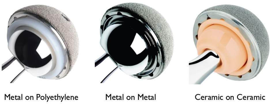
Prosthesis material combinations
Metal-on-metal (MOM) prosthetics are artificial joints where both the femoral head and acetabular cup are made of metal, usually a titanium or cobalt-chromium alloy. MOM prosthetics have better wear properties that metal-on-polyethylene (MOP) prosthetics; they have a lower linear wear rate and a decreased volume of particles. Moreover, MOM prosthetics have larger sized femoral heads which allows for an increased ROM before impingement. There are, however, many disadvantages to MOM prosthetic designs; more expensive than metal-on-polyethylene
- increased metal ions in serum and urine (5-10x normal)
- serum metal ion concentration highest at 12-24 months
- correlates with the initial “wear in” or “run-in” phase of increased particle generation, but then followed by a “steady state” phase of decreased particle generation
- no proven cancer link
- may form pseudotumors
- hypersensitivity (Type IV delayed type hypersensitvity)
- mediated by T-cells
- metals sensitize and activate T-cells (nickel > cobalt and chromium)
- however, most participating cells are macrophages (only 5% are lymphocytes)
- antigen-activated T-cells secrete cytokines that activate macrophages
- activated macrophages have increased ability to present class II MHC and IL-2, leads to increased T-cell activation
- the cycle continues
- contraindications
- pregnant women
- renal disease
- metal hypersensitivity due to metal ions
Metal-on-polyethylene prosthetics have a plastic acetabular cup and a metal femoral head. The benefits of MOM prosthetics is their low cost, modularity and long track record of bearing surfaces. The advantages of this design is the higher wear and osteolysis rates compared to metal-on-metal and ceramic designs. The MOP prosthetics also have a smaller femoral head size, which can lead to a higher risk of impingement.
Ceramic-on-metal (COM), ceramic-on-polyethylene (COP) and ceramic-on-ceramic (COC) prosthetics are artificial joints with a metal femoral head and metal, polyethylene or ceramic acetabular cup, respectively.
benefits of COC
- best wear properties of all bearing surfaces
- lowest coefficient of friction of all bearing surfaces
- inert particles
- no concern for cancer risk
- disadvantages
- more expensive than metal-on-polyethylene
- worst mechanical properties (alumina is brittle, low fracture toughness)
- small 28mm heads only exist in zirconia because of alumina’s inferior mechanical properties
- squeaking
- increased risk with
- edge loading
- impingement and acetabular malposition
- third-body wear
- loss of fluid film lubrication
- thin, flexible (titanium) stems
- less modularity with fewer neck length options
- stripe wear
- caused by contact between the femoral head and rim of the cup during partial subluxation
- results in a crescent shaped line on the femoral head
COP BENEFITS
- disadvantages
- zirconia undergoes tetragonal to monoclinic phase transformation with time

- increased with
- prolonged in vivo implantation >8yr
- pressure
- temperature
- has lower heat conductivity than alumina (joint temperature can reach 99oC for zirconia, and 50oC for alumina)
- increased with
- zirconia undergoes tetragonal to monoclinic phase transformation with time
REF: https://www.orthobullets.com/recon/5033/tha-prosthesis-design
USE PICS FOR PRESENTATION
The latter is less common but very useful for THA where the patient is allergic to metals.
Prosthesis design
The purpose of this study is to simulate a Finite Element Analysis (FEA) of the artificial hip joint under different loads representing various non-western activities. Non-western activities investigated include the patient squatting, sitting on a chair, sitting on legs fully flexed the knee and bowing while sitting on legs fully flexed at the knee. These positions are commonly used for eating, socialising, defecation and religious/traditional ceremonies. The results of this analysis will help predict aseptic loosening due to impingement and/or bone-prosthesis micromotion.
Literature Review
Introduction
A structure is a geometrical configuration of materials created to withstand loads. Structural analyses are used to predict the stresses that may act on the structure when it is loaded. This gives the opportunity to evaluate thequality and adequzcy of it’s design and materials in terms of fulfilling load bearing functions.
The stress distribution within a loaded structure depends on five things [hussan]:
- The magnitude and configuration of loads. This is what is reforred to as the loading conditions of the analysis
- TRhe geometry of the structure/model
- The material properties of the structure/model
- The boundary conditions; These conditions describe the connection the model has with the environment
- Interface conditions; These condition describe the connection between the different material surfaces
These five aspects must be described either mathematically or physically.
A theoretical stress analysis is used to model the structure mathematically while and experimental stress analysis is used to model the structure physically.
There are different structural analysis methods under the umbrella term of theoretical stress analysis and experimental stress analysis. According to [hussan 69], the tools of structure analysis can be listed as experimental methods including photoelasticity, strain gauging, brittle laquer coating and holography. [EXAMPLE OF EACH]
For a theorectical stress analysis, closed form theories can be very useful. The se unclude but are not limited to; the beam theory (beam on elastic foundations, composite beams), the torision theory, the thin shell/thick shell theory and the buckling theory.
Structure modelling can also be executed through numerical methods such as finite element analysis. This will be the main focus of this study.
Each method has it’s own advantages and disadvantages when used to analyse biomechanical structures and systems.
Numerical methods have proven to be the best option for the analysis of biomechanical structures as they accommodate the complexity of biomechanical systems very well.
Experimenta stress analyses have been carried out for the artificial hip joint, for examples [REFERENCES OF EXPERIMENTAL ANALYSES]
Numerical methods, particularly finite element methods have also been used in previous studies to analyse artificial joints as seen in the works of [REFERENCES]
As well as being useful for deisgn analysis, the finite element method has also proven to be very useful in orthopaedic biomechanics cases as a tool for basic research.
With up to ___ total hip replacement operations carried out every year, finite element modelling has become very common. Various literature has been reviewed in order to evaluate findings from previous studies and build upon them. This is to ensure the outcomes of the present work will make a valuable contribution to the bioengineering community. There are three main areas of focus to be explored in this study regarding the effect of the loading regime during the finite element analysis of the artificial hip joint. These three topics will be: bone-prosthesis interface micromotion/aseptic loosening, femoral neck impingement/early dislocation, and prosthesis fatigue life approximation.
Interface Micromotion and Aseptic loosening
Natural stress distribution is significantly different after a total hip replacement surgery. After the total hip replacement surgery, the amount of stress distributed through the bone is reduced; the location of the stress is shifted so it acts through the prosthesis. This effect is commonly referred to as bone stress shielding. As a response to the change in mechanical environment, there is a resulting loss of bone mass through the biological process called resorption [ref]. [EXPLAIN RESORPTION]. Resorption can ultimately cause aseptic loosening.
Aseptic loosening is one of the major concerns following total hip replacement surgery. Much like resorption, the following may also cause aseptic loosening;
Any gap left between the bone and the hip joint implant when inserting the implant during surgery [19]
Biological reactions caused by polyethylene, polymethyl methacrylate and/or metal debris from prosthesis wear and tear [20]
Relative motion across interfaces [Chong et al.]
Mechanical stress modifications induced by the implant, be it stress shielding or local overloading
Mechanical failure of the implant (or cement in applicable cases)
Generally, aseptic loosening is usually the result of either mechanical factors (such as material, design geometry, and/or patient factors, for example, soft tissue growth at the bone cement interface, and the unique pathology of the individual. Mechanical factors are much easier to control than patient factors [25]. Mechanical factors can be controlled by improving materials selected and/or prothesis geometric design.
The literature reviewed will be focused on investigating and optimizing mechanical factors.
Impingement and Early Dislocation
A study was carried out by Eko Saputra et al. in 2013 performing a finite element analysis of the artificial hip joint’s movement during human activities.
The purpose of the study was to evaluate the risk of early artificial joint dislocation and impingement, by predicting the resisting moment in a variety of western style and Japanese style activities. The activities investigated in the study were activities that involve deep hip bending movements with different ranges of motion. The relation of the resisting moments, the internal rotation and the von Mises stress were reported.
The finite element model of the contact system consisted of the femoral head, femoral neck and acetabular liner cup. The femoral head and neck were assumed to be rigid while the acetabular liner cup component is modelled as an elastic-plastic material with isotropic hardening. It is modelled as Ultra High Molecular Weight Polyethylene (UHMWP0 with visco-elastic-plastic material behaviour.
The geometrical modelling of the unipolar artificial joint follows the model Kluess et al. The model is meshed in the finite element software ABAQUS with approximately 9000 elements. The element type was hexahedral eight nodes linear brick (C3D8R)
The value of the load applied to the model was taken from studies by Kluess et al. while the direction of the force follows the work of Bergmann et al.
During the simulations run by Eko Saputra et al., the acetabular liner cup positioning was varied for each human activity studied. And for each human activity, all degrees of freedom at the outer surface of the acetabular liner cup remained fully constrained. As the load is applied to the centre of femoral head, the femoral head is left only partially constrained to allow for rotational motion. This is vital in evaluating the risk of impingement occurring at the location where the acetabular liner cup lip and the femoral neck make contact.
The results of this study predicted the resisting experienced by the artificial hip joint as a result of the different loading conditions. Loading conditions were modelled as representations of the following western style and Japanese activities:
1. Western style activities (on a chair);
a. Picking up an object while sitting on the chair
b. Getting up from the chair
c. Sitting down on the chair
2. Japanese style activities (on the floor);
a. Bowing while sitting on legs fully flexed at the knee (“zarei” in Japanese)
b. Squatting
c. Sitting on legs fully flexed at the knee (“seiza” in Japanese)
The developed model was in agreement with the literature reviewed.
A conclusion was made from the results that most activities could be performed safely by a patient, of approximately 70kg, after total hip replacement surgery (and after a post-surgery recovery period of ____).
Impingement and early artificial joint dislocation were predicted to occur for activity 1a (western style; picking up an object while sitting on the chair). Activity 2c (Japanese style; sitting on legs fully flexed at the knee, “seiza”) was not recommended for patients after their post-surgery recovery period, as the safety margin of the internal rotation was less than 10⁰. Furthermore, when the simulation for activity 2c was run, it was found that the von Mises stress at the impingement position was higher than the yield strength of the material. This means that________.
One of the main aims of the present work is to investigate further the effects of the loading conditions on the total hip replacement (including the femoral stem component implanted in and fixed to the femur bone).
Fatigue Life Estimation
The present study also aims to investigate the effects of loading conditions representing fast walking a focus area inspired by previous studies [5, 11, 15, 21].
This section will review literature from a Materials Today journal; “Fatigue Life Estimation of Artificial Hip Joint Model Using Finite Element Method” (Zameer, 2015)[15]. The article uses results from a static analysis, such as the von mises stress distribution, in collaboration with mathematical theories, specifically the Good man stress fatigue concept and the Palmgren Linear Damage Rule, to produce an estimate of the fatigue life of the hip joint model.
The artificial hip joint model was developed using CATIA solid modelling package. Zameer used the experimental data on standardized human femur anthropometry found in the work of Ziylan T. et al. [23] when developing the artificial hip joint model. The model produced also considered optimized design variables parameters, as reported by Sivasankar, M. [22], in order to build the model.
The artificial hip joint model consisted of the following dimensions: the radius of the femoral head was of diameter 27mm, the inclination of the femoral neck was about 45⁰, the femoral stem outer radius was 9.93mm, the stem inner radius was 8.04mm and the femoral neck length 50.97mm, and the length of the femoral stem was 172.25mm. The femoral stem shape was in the form of a truncated cone with a tapered cross section. This prosthesis design was selected for analysis as the femoral stem shape was expected to reduce stress distribution, reduce the risk of aseptic loosening of the prosthesis material and increase the prosthesis fatigue life and stability. The femoral stem was assembled in the cortical bone and the bone-prosthesis interface is assumed to be bonded via osseointegration. The model was tetra meshed due to complicated geometry with internal Cancellous and cortical bones.
Unlike most previous studies, this model of the artificial hip joint does not consist of a metal prosthesis. Instead, a fabricated polymer matrix composite material was assigned to be the prosthesis material. This is because most research based on the use of metallic biomaterials as the primary material for artificial hip joint femoral stem show results of stress shielding affect (adding to the risk of aseptic loosening, again) caused by a mismatch in properties of cortical bone and prosthesis materials [24]. The artificial hip joint system model in this study was modelled as having the following materials: cancellous bone, cortical bone, ultra-high molecular weight polyethylene (UHMWPE)/TiO2 polymer composite, Cap. The materials properties are shown in Table x.x.
Table x.x: Material properties [15]
Material Modulus of Elasticity (MPa) Poisson’s ratio Yield Stress (MPa)
Cancellous Bone 600 0.2 15
Cortical Bone 15,000 0.3 210
(UHMWPE)/TiO2 Polymer Composite, 7,500 0.4 35.6
Cap 7,500 0.3 35.6
The finite element analysis was executed using the software ANSYS version 11. A total of four separate static analysis simulations were carried out. Initial conditions and boundary conditions remained the same throughout all four simulations; A normal right hip in one leg standing position, supporting the whole-body weight was considered. The loads were determined from experimental observations of Bergmann et al., considering and average patient weight of 70kg. All the nodes located at the bottom of the femur bone and the outer surface of the acetabular cup were fully constrained in al degrees of freedom.
The four simulations were carried out with different loading conditions to represent different human activities; fast walking, normal walking, knee bending and walking down a staircase. For these activities, vertical loads of 1304N, 1270N, 431.9N and 1473N were applied on the centre of the femoral head, respectively. An abductor muscle force of 1937N at an angle of 20⁰ to the proximal area of greater trochanter is considered. All loads which were applied to the hip joint model acted in terms of percentage of body weights.
From the results of the static analysis, fatigue locations in the hip joint can be understood. Von mises stress distribution results obtained needed to be lower than the endurance limit of the femoral stem material (interpreted from the prothesis material yield stress) in order to avoid fracture due to fatigue. Keeping this in mind will allow for an optimized safety design of the artificial hip joint.
Overall, the results of this study showered maximum stressed were concentrated on the femoral neck portion of the artificial hip joint compared to the bottom of the femur bone. This can be seen in figures x, x, x and x.
The different contours in the figured display the variation of stress in the structure, with the maximum von misses stress distribution being 40.045MPa, occurring during the 4th activity; walking down a staircase. The von mises stress distribution results achieved from the static analysis are below the ultimate tensile strength of the prosthesis material.
Table x.x shows the maximum stresses and displacement observed during each activity.
Table x: Maximum stresses and displacement observed during each activity [15]
Activity Vertical Load (N) Maximum Stress (MPa) Displacement (mm)
Fast walking, fig. x 1304 45.485 1.611
Normal walking, fig. x 1270 30.323 1.074
Knee bending, fig. x 431.9 21.463 0.687
Walking down a staircase, fig. x 1473 40.054 1.103
Finally, fatigue life of the artificial hip joint was determined based on the Goodman mean stress fatigue concept. Ultimately the following results on effective alternating stress were calculated (after a fatigue analysis of fabricated composite specimens was conducted): COPY AND PASTE TABLE 2.
Bone-prosthesis Interface Micromotion for Cementless Prostheisis Fixation
Studies have been carried out to investigate specifically bone-prosthesis interface micromotion. An article was written by Desmond Y.R. Chong et al. on the analysis of bone-prosthesis interface micromotion for the cementless tibial prosthesis fixation and the influence of loading conditions.
Bone-prosthesis micromotion is known to be a cause of bone-prosthesis attachment failure [ref].
Methodology
Introduction to Finite Element Analysis
A basic theoretical outline of the numerical methods used in this study can be found in this section.
Finite element analysis can be used to solve a variety of physical problems [7] for example:
• Heat transfer and thermo-elasticity
• Fluid dynamics
• Fluid structure interaction with applications also in bioengineering
• Electromagnetism
The purpose of this chapter, however, is to describe the finite element method was applied to this study specifically, as oppose to a section dedicated to finite element methods.
Finite element analysis is the simulation of a physical system, taking into account the geometry and loading conditions, by a mathematical approximation of the real system.
The basic steps of finite element analysis are listed [7]:
1 Pre-processing;
• Create and discretize the solution domain into finite elements, that is, subdivided the problem into nodes and elements
• Assume a shape function to represent the physical behaviour of an element; that is, an approximate continuous function is assumed to represent the solution of an element
• Develop questions for element
• Assume the elements to present the entire problem.
• Apply initial conditions
• Apply boundary conditions
• Apply loading conditions
2 Solution phase;
• Solve a set of linear or non-linear algebraic equations simultaneously to obtain nodal results, such as displacement values at different nodes of temperature values at different nodes in a heat transfer problem.
3 Post-processing phase;
• Using the nodal values and interpolation functions, other parameters, such as, strain, stress etc. inside each element may be determined
FINITE ELEMENT ANALYSIS
Finite element is a numerical technique (or method) to solve
problems in different engineering fields.
The method is quite robust and it is readily available via different
software packages (commercial or open source).
Use of this package requires attention:
1) Clear understanding of the physics involved in the problem to
be examined.
2) Should be clear what are the questions we want to answer via
finite element analysis.
3) Clear understanding of modelling assumption.
4) Wise interpretation of results and model limitations
We need to create a MESH! Why?
Our aim is to find the solution (displacement, strain, stress)
everywhere.
The problem is too difficult to be solved analytically.
We decide to use a numerical approach (FEM) we create a grid and
we want to know the solution on particular points of the grid:
nodes.
Nodes are vertices of elements.
What about the displacement in
an internal point?
We know the displacement in
the nodes.
Using some special function
(interpolating or shape
function) we can obtain the
displacement in point ( ).
STRUCTURED OR UNSTRUCTURED MESH
Structured
Pro
The management, in term of memory usage
is more efficient
Contra
It is difficult to use a structured mesh on
complex geometry
It is more difficult to create (automatic)
adaptivity strategies in particular zones.
Unstructured
Pro
It can accomodate easily complex geometry
It is easier to produce adaptivity strategies
to redistribute element.
Many algorithms can be used to the
automatic generation of the mesh.
Contra
The management, in term of memory usage
is computational more expensive.
STATIC ANALYSIS
This is generally the starting point of finite element analysis.
The inertia forces (mass) are neglected and force is applied.
In theory we are assuming that the force is applied slowly (static
situation).
DYNAMIC ANALYSIS
This analysis is important
to avoid resonance between
an external load and the
structure.
In the case of resonance the
frequency of the external
load matches one of the
natural frequency of the
structure
In the transient dynamic we want to monitor the response of the
structure in time.
The loads are typically function of time and inertia plays an
important role on the overall behaviour.
In general the algorithm used is a direct integration method
known as Newmark method or similar as the HHT (HilberHughes-Taylor),
or the new Bathe implicit method(*)
.
Selection of the method can have strong effect on long time
behaviour structural response.
IMPLICIT VS EXPLICIT DYNAMICS
Explicit dynamic is used when the structure is subjected to large
deformations in a short period of time or when there are big
non-linearities as typical in contact mechanics simulations).
A classical example is provided by a car crash test.
In the case of low-speed dynamic the implicit approach is the
Standard
What is extracted from a finite element simulation
The primitive variable that is obtained through the solutions is:
1) Displacement.
Please remember that the displacement is a vector (with three components in
the 3D space).
2) Strains (deformation) are recovered from the displacement.
Strains are displacement derivatives respect to space.
In 3D we have 6 components of strains in each point.
3) Stress is finally obtained at the end of the process.
A constitutive law (material properties) need to be specified.
In 3D we have 6 components of stress in each point.
My method
Materials
A three dimensional CAD model of the femure bone and the hip joint prosthesis was used for this study. The bone model was created by [], through the means of ____. The hip joint prosthesis was designed by [] using the software ____.
For the pre-processing stage of this analysis, the bone was modelled as linear elastic and isotropic [EXAPLAIN WHY]. Both cancellous and cortical bone layers were considered as the differences in material properties, such as the elastic modulus and density, were largely significant. Using an average of the two would invalidate any results.
The cortical bone was set to have an elastic modulus of ____ and a poisson’s ratio of _______. These two properties were used to derive a number of other material properties such as the shear bulk modulus,_______.
The joint prosthesis is modelled with a femoral stem, a femoral neck and a femoral head made from a titanium alloy. [WHICH ALLOY AND WHY?]. The elastic modulus and poisson’s ratio were set to ____ and ____ respectively. The material properties of the different component studied in this analysis can be found in table 1.
Geometry
Model
RESULTS – STATIC ANALYSIS OF ALL 4 POSITIONS, ANSYS SCREEN SHOTS
Results/Discussion
Wear and tear => Fatigue life estimation (VON MISES STRESS INTO GOODMAN MEAN STRESS EQUATIONS). MUST CHANGE WALKING ANALYSIS SO SIMULATION STARTS AS FAST WALKING THEN NORMAL WALKING OR ELSE YOU WONT HAVE ENOUGH RESULTS TO CALCULATE A MEAN STRESS!!!! USE ALL WALKING LOADS AND MAGNITUDES FROM ZAMEER – THEN COMPARE RESULTS TO SHOW DIFFERENCE BETWEEN YOUR MODEL AND ZAMEER’S: DISCUSS DIFFERENCES BETWEEN MATERIALS, AND ANYTHING NEGLECTED OR ASSUMED (DUE TO TIME CONSTRAINTS OR FOR SIMPLIFICATION PURPOSES) THAT MAY CAUSE A DIFFERENCE IN THE RESULTS COMPARISON.
DISCUSS RESULTS, WHAT ARE THEY ACTUALLY TELLING US?
CONCLUSION– What we’ve learnt from this paper
References
[1] Bergmann, G., Deuretzbacher, G., Heller, M., Graichen, F., Rohlmann, A., Strauss, J., Duda G.N. (2001). Hip Contact Forces and Gait Patterns from Routine Activities. Journal of Biomechanics, 34(7), pp. 859-871.
[2] Heller, M.O., Bergmann, G., Deuretzbacher, G., Dürselen, L., Pohl, M., Claes, L., Haas, N.P., Duda, G.N. (2001). Musculo-skeletal Loading Conditions At The Hip During Walking and Stair Climbing. Journal of Biomechanics, 34(7), pp. 883-893.
[3] Lengsfeld, M., Bassaly, A., Boudriot, U., Pressel, T., Griss, P. (2000). Size and Direction of Hip Joint Forces Associated With Various Positions of The Acetabulum. Journal of Arthroplasty, 15(3), pp. 314-320.
[4] Stansfield, B.W., Nicol, A.C. (2002). Hip Joint Contact Forces In Normal Subjects And Subjects With Total Hip Prostheses: Walking And Stair And Ramp Negotiation. Clinical Biomechanics (Bristol, Avon), 17(2), pp. 130-139.
[5] Bergmann, G., Graichen, F., Rohlmann, A. (1993). Hip Joint Loading During Walking And Running, Measured In Two Patients. Journal of Biomechanics, 26(8), pp. 969-990.
[6] Mohammad Rabbani and Hossein Saidpour. (2015). Stress Analysis of a Total Hip Replacement Subjected to Realistic Loading Conditions. Journal of Robotics and Mechanical Engineering Research, 1(1), pp. 18-23.
[7] Moaveni, S. (2014). Finite Element Analysis: Theory and Application with ANSYS, Global Edition. 4th ed, Harlow: Pearson Education Limited, pp.
[8] Sugano, N., Tsuda, K., Miki, H., Takao, M., Suzuki, N., Nakamura, N. (2012). Dynamic Measurements Of Hip Movement In Deep Bending Activities After Total Hip Arthroplasty Using A 4-Dimensional Motion Analysis System. Journal of Arthroplasty, 27(8), pp. 1562-1568.
[9] Kluess, D., Martin, H., Mittelmeier, W., Schmitz, K.P., Bader, R. (2007). Influence Of Femoral Head Size On Impingement, Dislocation And Stress Distribution In Total Hip Replacement. Medical Engineering & Physics, 29(4), pp. 465-471.
[10] Saputra, E., Anwar, I.B., Jamari, J., Van Der Heide, E. (2013). Finite Element Analysis of Artificial Hip Joint Movement During Human Activities. Procedia Engineering, [online] 68, pp. 102-108. DOI; 10.1016/j.proeng.2013.12.154 [Accessed 29 Mar. 2018].
[11] Chong, D.Y.R., Hansen, U.N., Amis, A.A. (2010). Analysis Of Bone–prosthesis Interface Micromotion For Cementless Tibial Prosthesis Fixation And The Influence Of Loading Conditions. Journal of Biomechanics, 43(6), pp, 1074-1080.
[12] Andriacchi, T.P., Stanwyck, T.S., Galante, J.O. (1986). Knee Biomechanics And Total Knee Replacement. Journal of Arthroplasty, 1(3), pp. 211-219.
[13] Kienapfel, H., Sprey, C., Wilke, A., Griss, P. (1999). Implant Fixation By Bone Ingrowth. Journal of Arthroplasty, 14(3), pp. 355-368.
[14] Pettersen, S.H., Wik T.S., Skallerud, B. (2009). Subject Specific Finite Element Analysis Of Implant Stability For A Cementless Femoral Stem. Journal of Clinical Biomechanics, 24(6), pp. 480-487.
[15] Zameer, S. and Haneef, M. (2015). Fatigue Life Estimation of Artificial Hip Joint Model Using Finite Element Method. Materials Today: Proceedings, 2(4-5), pp. 2137-2145.
[16] Whitehouse, M. & Blom, A. (2009). The Use of Ceramics as Bone Substitutes in Revision Hip Arthroplasty. Journal of Materials, [online] 2(4), pp. 1895-1907. DOI; 10.3390/ma2041895 [Accessed 5 Apr. 2018].
[17] Shinge, A.R., Anasane, S.S., Aitavade, E.N., Mahadik, S.S., Mulik, P.V. (2011). Finite Element Analysis of Modified Hip Prosthesis. International Journal of Advanced Biotechnology and Research, 2(2), pp. 278-285.
[18] Şenalp, Z., Kayabasi, O., Kurtaran, H. (2007). Static, Dynamic And Fatigue Behaviour Of Newly Designed Stem Shapes For Hip Prosthesis Using Finite Element Analysis. Journal of Materials & Design, 28(5), pp. 1577-1583.
[19] Lars Carlsson, Tord Röstlund, Björn Albrektsson & Tomas Albrektsson (1988). Implant Fixation Improved By Close Fit Cylindrical Implant – Bone Interface Studied In Rabbits. Acta Orthopaedica Scandinavica, [online] 59(3), pp. 272-275. DOI: 10.3109/17453678809149361 [Accessed 24 Apr. 2018].
[20] Collier, J.P., Bauer, T.W., Bloebaum, R.D., Bobyn, J.D., Cook, S.D., Galante, J.O., Harris, W.H., Head, W.C., Jasty, M.J., Mayor, M.B., Sumner, D.R. & Whiteside, L.A. (1992). Results Of Implant Retrieval From Post-mortem Specimens In Patients With Well-functioning, Long-term Total Hip Replacement. Clinical Orthopaedics and Related Research, 274, pp. 97-112.
[21] Teoh S.H. (2000). Fatigue of Biomaterial – A Review. International Journal of Fatigue, 22, pp. 825-837.
[22] Sivasankar, M., Dwivedy, S.K., Chakraborty, D. (2007). Fatigue Analysis of Artificial Hip Joint for Different Activities. Department of Mechanical Engineering, Indian Institute of Guwahati. DOI: https://bit.ly/2JFKKHs [Accessed 4 May 2018].
[23] Ziylan, T. and Murshid, K.A. (2002). An Analysis of Anatolian Human Femur Anthropometry. Turkish Journal of Medical Sciences, 32(3), pp. 231-235.
[24] Ramakrishna, S., Mayer, J., Wintermantel, E., Leong, K.W. (2001). Biomedical Applications of Polymer-composite Materials: A Review. Journal of Composites Science and Technology, 61(9), pp. 1189-1224.
[25] Hussam El-Din F. El-Shiekh (2002). Finite Element Simulation of Hip Joint Replacement under Static and Dynamic Loading. School of Mechanical and Manufacturing Engineering, Dublin City University. DOI: https://bit.ly/2y1mUBj [Accessed 21 May 2018].
[26] Lu, T., Chang, C. (2012) Biomechanics of Human Movement and Its Clinical Applications. The Kaohsiung Journal of Medical Sciences, [online]28(2), pp. S13-S25. DOI: 10.1016/j.kjms.2011.08.004
Cite This Work
To export a reference to this article please select a referencing stye below:
Related Services
View all


Related Content
All TagsContent relating to: "Physiotherapy"
Physiotherapy is the practice of targeted exercise and movement to provide rehabilitation and restore or improve function and correct movement following injury, illness, or disability. Physiotherapy can also help to maintain health and prevent future debilitation.
Related Articles

DMCA / Removal Request
If you are the original writer of this dissertation and no longer wish to have your work published on the UKDiss.com website then please: