Analysis of Interlocking Brick Mechanical Responses
Info: 10358 words (41 pages) Dissertation
Published: 9th Dec 2019
Tagged: ConstructionBuilding Materials
It was only recently that segmentation or fragmentation has been used to produce new materials and structures with exceptional performance. The concept of topological interlocking as an engineering design principle started gaining popularity in materials engineering community in the past decades. A potent tool for developing fragmented materials and structures is topological interlocking, in which the elements are held together without any binder or connectors. This means that the elements are designed with a special shape and arranged in such a way that the whole structure can be held together by a global peripheral constraint. The shape and mutual arrangement of the elements cause the elements are kept in place just by kinematic constraints. In essence, topological interlocking is a way to combine the structural flexibility, tolerance to local failures, enhanced crack propagation resistance and structural stability against missing elements.
So far, very limited reports can be found to experimentally and numerically study the dynamic behaviour of interlocking structures. In this study, a new design of interlocking brick has been developed and the dynamic mechanical response of this interlocking brick is extensively studied numerically and experimentally. Firstly, a number of experimental tests have been conducted on both the monolithic concrete plate and plate-like assemblies made of the new interlocking bricks by drop weight tests. In the second part of this study, numerical modelling similar to drop weight tests is accomplished and the results of the experiments are validated with the numerical analysis. It has been shown that the simulation results are in good agreement with the experiments. In the next step, with the validated numerical models, a comparative study between new and existing osteomorphic brick which is presented by previous researchers has been conducted numerically. The results show that the newly interlocking bricks have much more uniform load, stress and deformation distribution during the impact than existing osteomorphic brick. In the last part of this study, the mechanical response of a hybrid structure consists of new interlocking bricks and rubber as filler between the bricks is studied. A number of quasi-static tests on the monolithic concrete plate, plate-like assembly made of the new interlocking bricks and the hybrid plate made of new interlocking bricks and rubber have been conducted. A series of numerical modellings to validate the experimental results have been accomplished.
| CHAPTER 1 | ||
| INTRODUCTION |
Chapter 1: Introduction
1.1. Background of the subject
In the past decades, segmentation and fragmentation have been used to produce new materials and structures with outstanding performance [1-3]. A potent tool for developing fragmented materials and structures is topological interlocking. The principle of topological interlocking is to build structures with elements that are held together by kinematic constraint without using binder or connectors. It allows certain degrees of relative movement of the building elements [4-11]. To date, the concept of topological interlocking has been used as an effective way to design new materials and structures [12-14].
There are a number of advantages in fragmented nature of new structures or materials made of topological interlocking. Indeed, topological interlocking is a way to combine flexibility, resistance to local failures and prevent crack propagation which are achieved by fragmentation of a material with its overall structural integrity [8]. New interlocked structures or materials with suitable flexibility can be made with brittle materials such as concrete, ceramic, ice and etc. as base materials, which are able to resist out of plane bending, avoid failure under high amplitude vibrations and dissipate energy. For example, concrete is always used as structural materials for different applications due to the combination of high compressive strength, durability, excellent thermal mass and convenience performing .The major difficulty in the application of the concrete is its relatively low fracture tolerance in tensile stresses and consequently low resistance and flexibility against out of plane loadings. Also, in concrete and other brittle material, cracks propagate with high speed when the load is exceeding the fracture strength, which leads to sudden failure of components. A number of technologies have been developed to enhance fracture resistance and flexibility of these brittle materials, such as grain refinement, addition of fibers or particles , or reinforcement with a second phase [10].One method to overcome low fracture toughness is the use of segmented structures, instead of monolithic ones. The segments can be held together by binder, keys and connectors, or by special geometry and arrangement of the segments. A created crack within a particular segment can be transferred into neighbouring segments through the boundary if a binder phase is used, but it remains confined within the segment if the connection is purely geometrical [10]. Another advantage of topological interlocking is the possibility to combine dissimilar materials as different segments which is important in creating hybrid materials [8, 15]. Furthermore, the interlocking principle makes it possible to assemble a structure from small blocks, thus providing decreasing possibility to failure for critical defects [5].
Another application of the topological interlocking concept is the use in designing and constructing of structures. An example of an accomplishment of this idea in building construction can be traced back to the self-aligning ancient Inca structures in which stability of the assemblies has been provided without any use of mortar or additional joints. These fragmented structures have shown high seismic resistance by distributing the loads through the structure. In fact, some of them are still in good condition as of today [14].
Over the last decade, the concept of topological interlocking of identical elements and its advantages over monolithic structures has received considerable research attention. Despite the extensive research on this subject, only one type of interlocking brick which is introduced in 2003 by Dyskin et al. [6] named “osteomorphic” brick has been studied so far. In our research, we reviewed the known geometries of existing interlocking brick and its arrangement and the properties of new obtained materials. We have presented a new design of interlocking brick with innovative topology and new arrangement. Also we have investigated the dynamic behaviour and characteristics of new resulting structure under impact force. The mechanical properties of a hybrid structure made of our new interlocking brick have been studied in last part of this research.
1.2. Research Objectives
In this study, we designed and made a new interlocking brick with innovative topology which can offer constraints in two planar directions. Also we investigated the effect of topology of our newly designed brick on the mechanical properties and behaviours of the interlocking structures including energy absorption capability, structural strength and stability under impact loadings compared with a monolithic one. We also perused the mechanical properties of hybrid structure made of combination of new interlocking brick and rubber as filer between the bricks. Flexibility, tolerance to local failure, energy absorption capability and overall stability of hybrid structure were studied under quasi-static loading and compared with interlocking structure without rubber and monolithic ones.
Hence, the objectives of this study are as follows:
- To design and construct a new topology interlocking brick which have different performance than existing designs;
- To investigate the characteristics of newly designed interlocking structures i.e. energy absorption capability under impact loadings;
- To study the properties of hybrid structures made of different materials including soft interfaces between concrete interlocking bricks.
- To validate numerical simulations and computational modelling for the interlocking brick systems under different loading conditions with experimental tests results;
1.3. Knowledge Gap and Contribution
- Only one type of topological interlocking brick has been studied.
- There is no existing strategy to generate different types of interlocked elements.
- There is very limited experimental study on the dynamic behaviour of interlocking structures.
- Very limited studies have been conducted on hybrid structures made of interlocking bricks.
1.4. Research Questions
As explained in the section 1.2, this study is going to design new topology and arrangement of interlocking brick and investigate the properties and characteristics of structure made of this new bricks. To achieve the above mentioned aims, the following research questions are addressed:
- What are the dynamic properties of interlocking structures under impact loadings i.e. the energy absorption and structural flexibility?
- What is the effect of lateral confining stress on the structural behaviours?
- What is a validated numerical model which can simulate the dynamic and static behaviour of interlocking structures?
- In terms of out-of-plane behaviour what is the difference between new design interlocking structure, existing one and monolithic plate?
- What are the behavioural differences and characteristics of hybrid interlocked structure with soft interfaces and simple interlocking structure and monolithic ones?
1.5. Thesis Outline
Chapter 2 provides a detailed literature review of existing interlocking structures. The experimental and numerical studies conducted on the interlocked structures are also investigated. The applications of these structures in previous researches are also presented.
Chapter 3 propose a new type of interlocking brick. The mechanical response of interlocking assembly plates by applying different levels of impact force and lateral confining load have been investigated by a series drop weight tests.
Chapter 4 presents an extensive numerical study on the impact behaviour of plate-like assemblies made of interlocking concrete bricks. The impact responses of both monolithic and assembly plates are investigated, and the numerical model is validated by comparing the predicted results with experimental data presented in chapter 3. A comparative study is also carried out on the assembly plates made of two types of interlocking bricks including existing osteomorphic brick and newly designed interlocking brick.
Chapter 5 investigates the mechanical properties of a hybrid interlocking structure with soft interfaces between its elements under quasi-static loading experimentally and numerically. The behavioural differences between hybrid structure and interlocking structure with purely geometrical connections and monolithic plate are studied.
Chapter 6 presents a summary of the study and discussing the outcomes of the research, followed by the conclusions of the study and an outline of future research directions.
1.6. References
[1] A.V. Dyskin, Y. Estrin, A.J. Kanel-Belov, E. Pasternak, A new concept in design of materials and structures: assemblies of interlocked tetrahedron-shaped elements, Scripta Materialia, 44 (2001) 2689-2694.
[2] M. Glickman, The G-Block System Of Vertically Interlocking Paving, Proc. 2nd Int. Conf. On CBP, (1984) 345-348.
[3] D.A. Robson, Verbundsteine, German Patent DE-AS 2 554 516, (1978).
[4] A. Dyskin, E. Pasternak, Y. Estrin, Mortarless structures based on topological interlocking, Front. Struct. Civ. Eng., 6 (2012) 188-197.
[5] A.V. Dyskin, Y. Estrin, A.J. Kanel-Belov, E. Pasternak, Toughening by Fragmentation—How Topology Helps, Advanced Engineering Materials, 3 (2001) 885-888.
[6] A.V. Dyskin, Y. Estrin, E. Pasternak, H.C. Khor, A.J. Kanel-Belov, Fracture Resistant Structures Based on Topological Interlocking with Non-planar Contacts, Advanced Engineering Materials, 5 (2003) 116-119.
[7] A.V. Dyskin, Y. Estrin, E. Pasternak, H.C. Khor, A.J. Kanel-Belov, The principle of topological interlocking in extraterrestrial construction, Acta Astronautica, 57 (2005) 10-21.
[8] Y. Estrin, A.V. Dyskin, E. Pasternak, Topological interlocking as a material design concept, Materials Science and Engineering: C, 31 (2011) 1189-1194.
[9] H.C. Khor, A.V. Dyskin, E. Pasternak, Y. Estrin, A.J. Kanel-Belov, Integrity and fracture of plate-like assemblies of topologically interlocked elements, Structural Integrity and Fracture. Swets & Zeitlinger, Lisse, (2002) 449-456.
[10] T. Krause, A. Molotnikov, M. Carlesso, J. Rente, K. Rezwan, Y. Estrin, D. Koch, Mechanical Properties of Topologically Interlocked Structures with Elements Produced by Freeze Gelation of Ceramic Slurries, Advanced Engineering Materials, 14 (2012) 335-341.
[11] A. Molotnikov, Y. Estrin, A.V. Dyskin, E. Pasternak, A.J. Kanel-Belov, Percolation mechanism of failure of a planar assembly of interlocked osteomorphic elements, Engineering Fracture Mechanics, 74 (2007) 1222-1232.
[12] L. Djumas, A. Molotnikov, G.P. Simon, Y. Estrin, Enhanced Mechanical Performance of Bio-Inspired Hybrid Structures Utilising Topological Interlocking Geometry, Scientific Reports, 6 (2016) 26706.
[13] A. Molotnikov, R. Gerbrand, O. Bouaziz, Y. Estrin, Sandwich Panels with a Core Segmented into Topologically Interlocked Elements, Advanced Engineering Materials, 15 (2013) 728-731.
[14] M. Weizmann, O. Amir, Y.J. Grobman, Topological interlocking in buildings: A case for the design and construction of floors, Automation in Construction, (2016).
[15] M.F. Ashby, Y.J.M. Bréchet, Designing hybrid materials, Acta Materialia, 51 (2003) 5801-5821.
| CHAPTER 2 | ||
| LITERATURE REVIEW |
Chapter 2: Literature Review
2.1. Introduction
To optimise the cost and technical characteristics of products, designers nowadays tend to integrate more and more functions into a single part, with the result that more requirements are placed on the part material. Different design strategies are possible depending on the situation: the designer may develop a new material, he may adapt an existing material, or he may define a combination of materials, in other words design a multi-material.
As a result, searching for a solution based on a monolithic material is often unsuccessful, and it becomes necessary to design a multi-material to find new solutions. The reasons that guide a designer to multi-materials are varied, so a few examples will be examined to take these reasons into account in a design method:
– Improving the performances of a part: It often happens that designers of a product increase the level of their requirements and want to improve performance, where performance is understood to be a level of obligation, such as increased strength or stiffness of a part, increased service life, reduced mass, decreased overall dimensions, etc. This increase in the level of obligations may render the search for a monolithic material unsuccessful as the screening parameters become more stringent.
– Incompatibility with the requirements: A search for monolithic materials may still be unsuccessful even when the level of constraint required is reduced considerably. This happens when constraints are incompatible: for example, the search may require a material that has both good thermal conductivity and high electrical resistivity.
– Integrating new functions into the material: More often the trend is for designers to integrate new functions into a material. No monolithic material can fulfil such a wide set of requirements.
– Reducing manufacturing or operating costs: This reduction may be linked with the cost of the material. A decrease in operating costs very often corresponds to a decrease in mass, which in the area of transport is correlated with an increased payload or reduced energy consumption.
– Facilitating manufacturing: The complex geometries that can be obtained when using composite materials often means a reduction in the number of parts needed to produce a unit;
– Not over-dimensioning the part: A part is not over-dimensioned if the functional requirements are fulfilled exactly. The number of free design variables is also the number of functional requirements verified without over-dimensioning. If this number of free design variables is increased when designing multi-materials in accordance with material selection then over-dimensioning of the parts can be reduced.
This list of reasons explains why a search for a monolithic material may prove unsuccessful. This preliminary analysis will be used in the search for the multi-material solution. [1]
Just as in the search for a monolithic material, the proposed multi-material design method starts by setting out the material requirements, based on the functional requirements of the part. Next, an expert questionnaire has to be created. The expert questionnaire depends on the application domain for which the multi-material is intended and on the experience of the designer. The main questions are:
– Which materials are closest to the target objectives?
– What constraints prevent a monolithic material being selected?
– Are the requirements in the specifications compatible?
– Is there an architecture that is already used in this type of application?
– Are there components that can be fixed?
– …
There are several strategies to develop and design multi-material which meet desired and specified requirements intended by designer.
For example, concrete is always used as structural materials for different applications due to the combination of high compressive strength, durability, excellent thermal mass and convenience performing. Over the past years, a remarkable range of tools and techniques in materials science has been developed to enable engineers to enhance the mechanical properties of concrete and to find new technologies to design hybrid materials [2] .The major difficulty in the application of the concrete is their relatively low fracture toughness. In concrete and other brittle material, cracks propagate with high speed when the load is exceeding the fracture strength, which leads to sudden failure of components. A number of strategies have been developed to enhance fracture toughness, such as grain refinement, addition of particles or fibres, or reinforcement with a second phase. One method to overcome low fracture toughness is the use of segmented structures, rather than monolithic ones. The segments can be held together by a binder phase, keys and connectors, or by special geometry and arrangement of the segments. A crack generated within an individual segment can propagate across the boundary into a neighbouring segment if a binder phase is used, but it remains confined within the segment if the connection is purely geometrical [3].
The aim of the topological tools is to search for one or more materials, knowing the representative behaviour curve of the multi- material if the architecture is known. This tool is a screening tool for selecting materials as potential components of the multi-material. This technique relies on classical materials selection. [1]
2.2. The concept of topological interlocking
Topological interlocking is a special kind of design of new materials that is based on segmenting a monolithic material into identical elements, or building blocks, which are engineered in such a way as to interlock with their neighbours by virtue of their shape and arrangement alone, that is, without any need for binder or connectors[4]. The neighbouring elements interact with each other through interfaces and can carry transverse loads provided that there is some lateral constraint on the assembly. Lateral constraints are necessary as the blocks situated at the edges of an assembly do not have the sufficient number of neighbouring elements to lock them in [5].
In 1975, Robson [6] presented a concept on interlocking bricks with concavo-convex surfaces. An element of this kind is able to connect to its six neighbors through matching concavo-convex and planar interfaces, and a planar assembly of such elements can be formed in which every element is held in place by its neighbors kinematically. The structure shows resemblance with masonry stonewalls, which are often arranged in a herringbone pattern. What is essential with the element geometry proposed by Robson is that the motion of the elements is constraint in any direction, including the one normal to the planar assembly. The concept did not lead to any large-scale production, possibly since manufacturing techniques of complex shapes in the early 1970s were not well developed and were very costly. The concept that focuses on the binder-free connection of elements of a segmented structure via specially designed surface geometries was reintroduced in 2001 by Dyskin and co-workers and is known as topological interlocking [7, 8]. For instance, it was proven that all Platonic bodies (tetrahedrons, hexahedrons/ cubes, octahedrons, dodecahedrons, icosahedrons) are able to form structures from which no element can be removed without disassembly of at least part of the structure [8]. Further building block geometries permitting this kind of topological interlocking were developed over the last decade [9].
A mathematical formulation of the principles guiding rational design of topologically interlockable elements was given by Kanel-Belov et al [10].
2.2.1. Mortarless structures
Modern construction techniques are essentially based on the centuries-old method of assembling a structure from building blocks strongly connected to each other. It underlies both the ubiquitous brick-and-mortar construction and that with the reinforced concrete blocks or panels whose reinforcement rods are welded together. Even the existing mortarless structures based on conventional interlocking bricks (e.g., [11-14] ) rely on various keys and connectors to keep the blocks together. They are built of bricks or other building elements connected by specially designed keys or connectors (e.g., Vasco Costa, 1993; Anand & Ramamurthy, 2000; Gilroy & Goffi, 2001). Keys or connectors can themselves provide a medium (network) for fracture propagation, not to mention the fact that they are stress concentrators. The main role mortar or connectors play is to prevent sliding of the building blocks relative to each other. Furthermore, given the usual low tensile strength of mortar and connectors the resistance to tensile stresses (created for instance by bending) is primarily ensured by the weight of the structure aided in some cases by the arch effect [15]. At the same time mortar and connectors make the structure stiffer which reduces its resilience to vibrations and seismicity. On the other hand, the strong binder phase provides a medium that can easily transmit cracks from one element to another. Thus, for the purpose of increasing fracture toughness it would be beneficial if the binder was weak or even absent altogether [16]. Indeed, the known mortarless structures whose blocks have some degree of free relative movement, such as dry stone walls [17] and the classical temples (e.g., [18]), have survived for centuries even in seismic zones. Obviously, it is the ability of the blocks to move relative to each other and, in the process, dissipate the vibration energy, which underpins the longevity of these structures. However, the only factors that hold the blocks in place are weight and friction.
Recently, the principle of topological interlocking was introduced [4, 7-9, 16, 19-22] with a potential to build mortarless structures whose elements are prevented from being fully extractable from the structure, while allowing some degree of relative movement. Topological interlocking is a method to design the special shapes of the building blocks and the corresponding topologies of their assemblies such that no internal block can be removed from the assembly held by kinematic constraints imposed by its neighbors. (In Goodman and Shi’s [23] terminology, these are structures without key blocks.) Only the blocks on the periphery of the structure need to be constrained independently. In construction engineering this can be accomplished either by the weight of surcharge (or their own weight) or by constraining frames, pre-tensioned tendons or cables. Topological interlocking, while providing structural integrity, permits some restricted movement of the blocks relative to each other. This ensures that cracking does not occur during high amplitude vibrations (e.g., seismic vibrations) and that the vibration energy is dissipated due to friction between the moving surfaces. The shapes of blocks allowing topological interlocking include those of convex polyhedral, such as all five platonic shapes (tetrahedron, cube, octahedron, dodecahedron and icosahedron; see the three examples in Figure 1) and their truncated derivatives (including buckyballs) [10, 24, 25] as well as blocks with specially engineered shapes, such as osteomorphic blocks having two concavo-convex surfaces [8], Figure 2. The latter are especially attractive as they allow assembling 2D and 3D structures without gaps, Figure 3. (While the interlocking of blocks of tetrahedral shape and their truncated derivatives, as well as the shape of osteomorphic block, were proposed before [6, 26], the principle of topological interlocking provided a systematic method of designing new interlocking shapes.) [27].
Dyskin et al. [19] conducted some initial indentation testing of a plate-like assembly of tetrahedra and found that the interlocking assembly possesses a very high bending flexibility as compared to a solid plate of the same thickness, and that it can accommodate large plastic deformations. Dyskin et al. [19] suggested further shapes that possess the interlocking property [16]. In what follows, our focus will be on the structures that can be built from osteomorphic blocks.[27]
2.2.2. Types of interlockable elements
Two families of interlockable blocks, which permit topological interlocking, include convex polyhedral (Figure 1) and elements with non-planar surfaces (Figure 2). The first family studied by Dyskin and co-workers comprises all platonic bodies (tetrahedron, cube, octahedron, dodecahedron, and icosahedron) and their derivatives [8, 20].
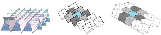

Figure 1- polyhedral interlocked elements (a) interlocked tetrahedral (b) interlocked cubes (c) interlocked octahedral.
The second family of interlockable blocks utilizes matching concavo–convex surfaces. One example is the ‘osteomorphic block’ depicted in figure 2. The term ‘osteomorphic’ refers to the bone-like shape of the block [10], which utilizes matching concavo–convex surfaces. The osteomorphic blocks can readily be assembled to a plate (Figure 3a) or a corner structure (Figure 3b) and, with some modifications, to more complex structures. The resistance of the assemblies of osteomorphic blocks to removal or displacement of any block is provided by its neighbours, notably due to opposite inclinations of the faces of the osteomorphic blocks. No limitations are put on the choice of the material or the size of the building blocks by the purely geometrical principle underlying topological interlocking. Of course, an appropriate choice of the material (or several materials, in the case of a hybrid) needs to be made depending on the performance criteria for a particular application. Here one can rely on some strategies that are emerging in the context of multi-materials design [1]. As to the choice of the block size, a scaling law for the elastic stiffness of a planar assembly of tetrahedron shaped blocks as a function of the number of the blocks and their size can be used [5].
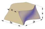
Figure 2- non-prismatic 3-Dimensional element (osteomorphic block)
2.2.3. Structures from osteomorphic blocks and their properties
Osteomorphic blocks can be assembled to three basic types of structures: a plate-like assembly, a corner structure and a column, Figure 3. These can be used to build all structural elements required in construction of a building, including walls, roofs and foundations. The properties of these structures, which define their possible applications, are discussed below [27].
(a) 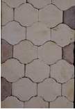 (b)
(b) 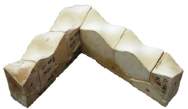 (c)
(c) 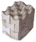
Figure 3- principle to assemble blocks to a (a) planar structure; (b) corner; (c) column.
2.2.3.1. Fracture resistance
The interfaces between the blocks can present obstacles to the fracture propagation [16, 19, 28]. Depending upon the magnitude of compression created by the constraint and the amount of friction at the interface, crack offset, may occur (see details in [29]). This increases the length and waviness of the crack trajectory, which additionally dissipates the energy required for fracture propagation. As a result, the cracking gets localized within separate blocks, rather than developing to a catastrophic crack [27].
2.2.3.2. Resistance to block removal
Topological interlocking provides high resistance to removal of the blocks. Furthermore, the interlocking plate-like assemblies of osteomorphic blocks are robust with respect to removal or full destruction of a number of blocks. Indeed, an assembly of osteomorphic blocks retains its load bearing capacity when some blocks are missing [16]. Computer simulations [21] showed that under random failure of osteomorphic blocks the structure resists collapse by percolation of damage until nearly 25% of the blocks fail.
2.2.3.3. Flexibility
Interlocking plates offer high flexibility over solid plates or plate-like structures made of brick and mortar [16]. This is another consequence of the absence of the binder phase. Increased bending compliance results from two factors:
1) The reduction in the in-plate elastic moduli associated with the presence of interfaces and
2) Reduced resistance to bending caused by partial loss of contact at the interface during bending. We call this phenomenon delamination; its model is considered in the following section.
2.2.3.4. Mobility and reparability
Topological interlocking offers a unique possibility of erecting demountable and hence movable structures. Indeed, once the constraint is removed, the whole structure can be disassembled, moved to another place and reassembled. Naturally, after disassembling all damaged blocks can easily be replaced or repaired. It should be noted, though, that repair of a block involves disassembling of part of the structure required to access the block. Alternatively, it may be possible to develop a procedure of repairing damaged blocks in situ, for instance by using special glues and fillers.
2.2.3.5. Negative stiffness
As the elements in the interlocking structures are not connected to each other mechanically, they retain the degrees of freedom associated with the movement of a solid body: three translational and three rotational ones. When the elements are assembled in an interlocking structure, their degrees of freedom become interdependent, owing to their non-round shape and to interlocking. One can expect that this interdependence may lead to unusual mechanical properties, in particular when a load is applied. In 2003, Y. Estrin et al. [7] have reported an anomaly in the behavior of assemblies of interlocked cubes found in unloading following a point loading test. In their study unusual mechanical response of a structure with topologically interlocked elements is discussed. Under point loading, it behaves pseudo-plastically, with a negative stiffness in part of the unloading curve. This effect is inherent in the structure and is attributed to changing contact conditions due to rotation of the elements.
As the cubes were made from different materials and the assemblies were tested in different loading apparatuses and under various lateral loads, this phenomenon is seen as an intrinsic property of the structure of interlocked cube shaped elements. It is believed to be associated with the rotational degrees of freedom and the variation of the character of the contact between the cubes under unloading. [7]
2.2.4. Manufacture and Mechanics of Topologically Interlocked Material Assemblies
Topologically interlocked material (TIM) systems are load-carrying assemblies of unit elements interacting by contact and friction. TIM assemblies have emerged as a class of architecture materials with mechanical properties not ordinarily found in monolithic solids. These properties include, but are not limited to, high damage tolerance, damage confinement, adaptability, and multifunctionality. The review paper prepared by T. Siegmund et al. in 2016 provides an overview of recent research findings on TIM manufacturing and TIM mechanics. They review several manufacturing approaches. Assembly manufacturing processes employ the concept of scaffold as a unifying theme. Scaffolds are understood as auxiliary support structures employed in the manufacturing of TIM systems. It is demonstrated that the scaffold can take multiple forms. Alternatively, processes of segmentation are discussed and demonstrated. The review on mechanical property characteristics links the manufacturing approaches to several relevant material configurations and details recent findings on quasi-static and impact loading, and on multifunctional response [30].
2.2.4.1. Methods of Manufacture for TIMs
1) Assembly. The discrete nature of TIM systems requires the use of some form of scaffold during manufacturing. The use of such scaffolds is common in the construction of arches and dome structures where self-weight are a central feature. For the engineering TIM systems of interest here, the topological interlocking geometry introduces additional constraints. On the other hand, there is no need to restrict considerations to the rigid scaffolds of civil engineering. For manufacturing of TIMs by assembly, the starting point is a plurality of (polyhedra) unit elements. Such unit elements can be produced by a range of methods, including conventional computer numerical control (CNC) machining, casting [3], or additive manufacturing [31].
1.1) Directional Pick and Place. Pick-and-place assembly processes use machine tools to place individual parts on predefined locations. Commonly, the individual parts are moved along the direction orthogonal to the assembly plane, and individual parts are not in contact with each other. For TIM systems assemblies, this basic pick-and-place approach is not possible as the interlocking geometry of the unit elements and the specific periodicity of the assembly introduces two additional constraints [30].
1.2) Parallel Assembly. Both directional pick-and-place methods require not only the exact positioning of individual unit elements but also the directed motion of unit elements along specific paths defined for each specific unit element [30].
1.3) Self-Assembly. Self-assembly of millimetre-sized particles has been described in the past [32, 33] yet without considering topological interlocking geometries.
2) Three-Dimensional Printing. Three-dimensional printing approaches allow for the integrated manufacturing of unit cells in the TIM in the final position together with the external constraint. Computer-aided design (CAD) software and scripting software are ideal tools to be applied for the creation of the geometric models for the TIM assembly [30] .
3) Segmentation. TIM panels can be manufactured as “top-down” in contrast to the bottom-up approach of assembling individual blocks or to 3D printing. In this strategy, the contours of the blocks are literally carved within a block of monolithic material [34]. This approach is advantageous because the blocks are created in their final position in the panel, and also because it can be implemented on final products or structures already in place, in order to augment their mechanical performance.
2.2.4.2. Mechanical response characteristics
1) Quasi-Static Loading. Figure 4 shows a key observation from investigations of the mechanical response of TIM systems under fixed external confinement subjected quasi-static loading applied in a transverse direction to the assembly plane. The monolithic equivalent system (a brittle glass plate) fails in a brittle mode with cracks extending throughout the plate; yet, the TIM exhibits a force–deflection response which appears as perfectly damageable [34]. Instead of a sudden drop in the force–deflection response for the brittle monolithic system, the TIM force response smoothly increases and decreases response with the applied deformation. No major cracks are visible in the TIM specimen. Similar findings are documented in Refs. [7, 35, 36]. In addition to the monotonic loading case, Estrin et al. [7] also considered unloading and partial unloading load paths and reported the finding of a negative elastic modulus. In order to further investigate the response of TIMs to mechanical loads, several investigators have employed numerical simulation tools. In discrete element simulations [36-38], the interaction law between discrete elements is obtained from finite element computations considering only two unit elements, and then, these interaction laws are imparted on the discrete element method (DEM) computation. DEM computations then capture the overall force–deflection response well [30].
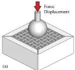

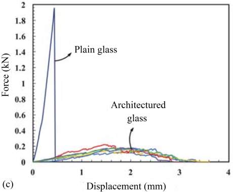
Figure 4- Quasi-static force–deflection response of transversely loaded TIM assembly and comparison to a monolithic equivalent: (a) schematic of experiment, (b) failure pattern in plain glass and architectured glass, (c) force–displacement response measured for plain glass and architectured glass
2) Impact Loading. Under impact loading, the resistance to impact, the damage tolerance, and the coefficient of restitution (or the residual velocity of the impactor) are of concern. Impact experiments on glass-based systems have demonstrated that the architectured TIM glass is both impact resistant and damage tolerant (Fig. 5). When compared to an equivalent monolithic glass panel, the TIM systems possess not only the higher impact energy to initiate failure but also a higher coefficient of restitution. Specifically, the TIM glass system manufactured by the laser-scribing processes could resist two to four times more impact energy compared to panels made of plain glass [34].
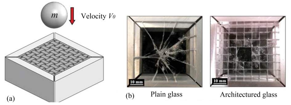
Figure 5- Impact characteristics for a glass-based TIM: (a) schematic of experimental setup, (b) failure pattern in plain glass and architectured glass
Computational simulations of the impact response of a TIM system were conducted for models where the TIM unit elements are elastic solid and for cases where the TIM unit element model domain is enhanced by cohesive zone elements [39]. Results from the computations including the cohesive elements and simulating the impact loading are shown in Fig. 6 where the failure due to impact for a TIM and the equivalent monolith are depicted.
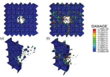
Figure 6- Finite element simulation of impact on (a) damage distribution in a TIM system and (b) damage evolution in the equivalent monolithic system. Simulations account for cohesive elements distributed evenly throughout the model volume.
The simulations are in good qualitative agreement with the experiments shown in Fig. 5. In the TIM case, the damage is confined to the domain around the impactor and in that region significant fragmentation is observed. Fragments are ejected from the TIM, and the kinetic energy is transferred from the impactor to the ejected fragments. On the other hand, in the monolithic case, the damage is widespread and reaches the system boundary. The amount of ejected fragments is small. In addition, a full set of residual velocity computations was performed for a TIM model with elastic elements, excluding damage to the unit elements.
3) Active TIM Systems. Confinement of the TIM plays an important role in defining the mechanical response of the TIM. In that sense, the TIM systems are not unlike granular materials. Since there is no restriction that the external rigid system boundary needs to be fixed in space during loading, the mechanical response of TIMs can actively be controlled. In Ref. [40], the authors employ active and adaptive control of the external constraints to achieve variable stiffness, including negative stiffness. This study furthermore demonstrates that active control allows holding the force constant over a large range of transverse deflection. Such a response is desirable for packaging and protection applications where energy dissipation at a controlled load level is needed.
In Ref. [5], it was shown that the control of the constraint can not only be achieved by controlling the constraint conditions through externally prescribed displacement of the rigid system boundary but also that the constraint can be changed in an autonomous way. In Ref. [5], shape memory wires embedded through channels in the unit elements span between the rigid system boundaries. Figure 7 depicts the TIM embodiment with unit cells as osteomorphic blocks and shape memory alloy (SMA) wires, as well as an example of the displacement and force response under SMA current on/off control.
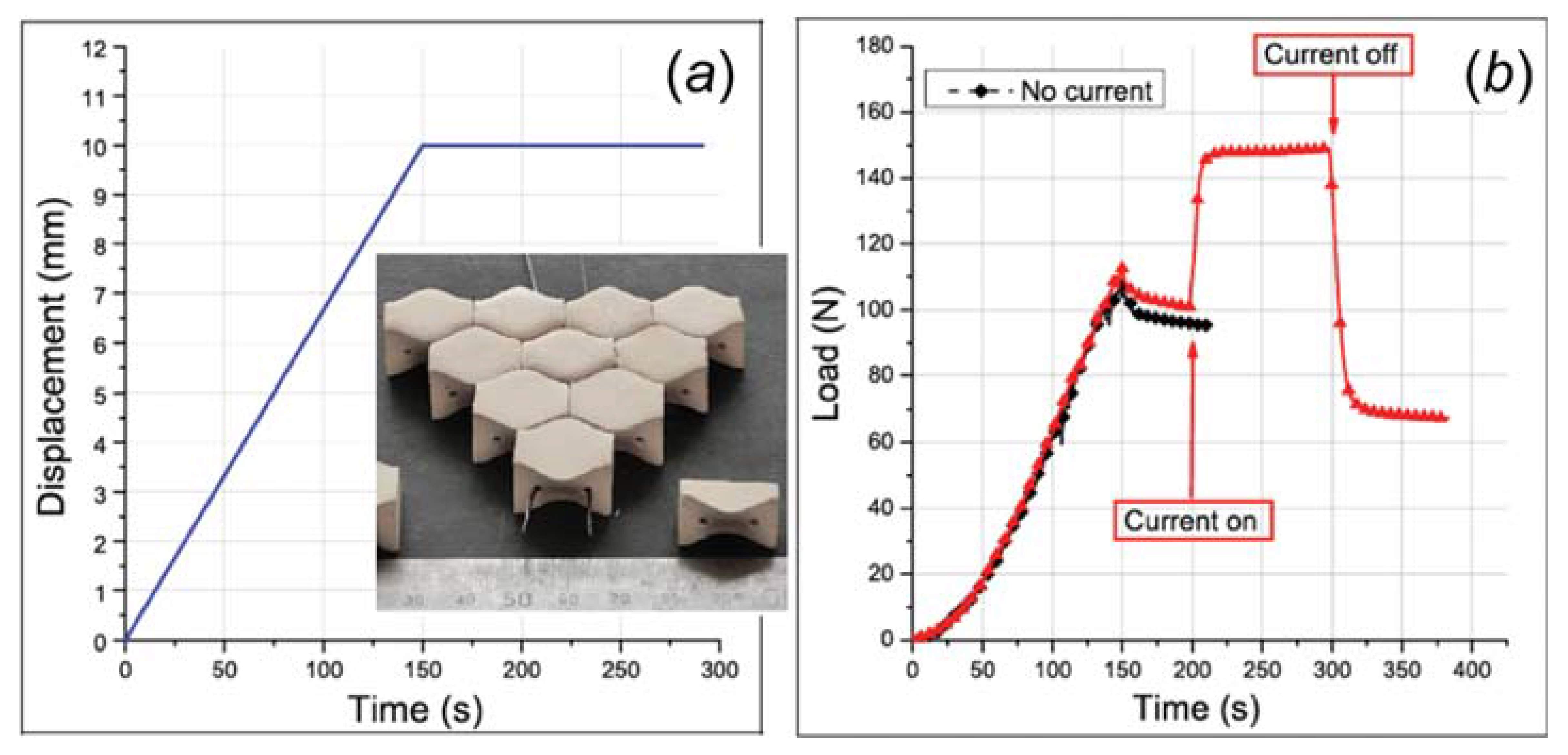
Figure 7- Control of mechanical response of a TIM by embedded SMA wires controlling the in-plane constraint: (a) imposed transverse displacement, insert depicts the TIM system composed of osteomorphic bricks and the SMA wires in channels through the brick units; (b) response of the SMA-enhanced TIM to SMA current during constant applied displacement. The current alters in in-plane constraint and thus the stiffness of the TIM [5].
2.3. Applications of topologically interlocked structures
2.3.1. Topological interlocking in buildings
The plate-like assemblies of topologically interlocked blocks can be used to construct flexible foundations that are insensitive to local reductions of the load bearing capacity of the ground and thus efficiently spread the load from the structure. In addition, being inherently segmented such foundations are permeable, which provides channels for dissipating excess pore pressure and thus reduce the risk of liquefaction. This feature, together with flexibility and high fracture resistance, can be important for seismicity-proof construction. Similarly, interlocking bricks can be used in pavements, especially in the cases when local settlement is to be prevented. Pavements based on osteomorphic blocks are straightforward as the exposed surfaces of the blocks are flat. Tetrahedral, cubic or octahedral blocks will have to be truncated to provide flat working surface for use in pavements. (This method was first proposed in [6], see also [41]). Another possible application of topological interlocking is in tilings, both protective and decorative. A particularly attractive possibility is to use such tilings in heat shields [42], cladding of furnaces and other similar applications. The main advantage of tilings of this type is an extended service time, since interlocked tiles can only be removed when completely destroyed [27].
In 2016, Weizmann et al. [43] have presented the results of a study that examines the potential of using the concept of topological interlocking as a structural and organizational mechanism for buildings. They have investigated the different application of topological interlocking in building as a case for the design and construction of floors. Their study presents a catalogue that characterizes the various types of topological interlocking systems and compares the potential of these types to be employed in buildings. This research created a framework for employing topologically interlocked (TI) based systems in building in general and in building floors specifically. It created a geometric catalogue that mapped valid TI formations based on regular, semi-regular and non-regular surface tessellation and it showed, via parametric geometric algorithm, a possibility to create valid TI assemblies on 2D and 3D grids.
Assembling the floor directly in the final location can be done after the construction of the main building’s frame structure. The assembly will be prepared on temporary scaffolding that will be removed immediately after all the elements are placed and an interlocking has been achieved (Figure 8). In order to be able to assemble the interlocking elements, the frames that are created by the main structure need to have an opening on one side during the assembly process (Figure 8).
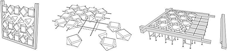
Figure 8- Assembly methods: a) assembly close to the final position — solid frame with topological interlocked elements; b) assembly close to the final position — flexible frame with topological interlocked elements; c) assembly in the final position — assembly on temporary scaffolding while using the building’s structure as a frame [43].
In terms of the structural analysis and optimisation the initial results show that a traditional solid slab will weight approximately 0.16 of the total weight of the examined TI system. Nonetheless, experiments show that by employing topological optimization methods it will be possible to considerably decrease the weight of the elements, and thus increase the cost effectiveness of the system. However, although topological optimisation process will probably reduce the unit weight, it will also increase the elements form’s complexity. This could have a significant influence on the fabrication costs [43].
2.3.2. Hybrid material
The properties of engineering materials can be mapped, displaying the ranges of mechanical, thermal, electrical and optical behavior they offer. These maps reveal that there are holes: some areas of property-space are occupied and others are empty. The holes can sometimes be filled and the occupied areas extended by making hybrids of two or more materials or of material and space. Particulate and fibrous composites are examples of one type of hybrid, but there are many others: sandwich structures, foams, lattice structures and more [2].
Topological interlocking has been suggested as a novel method to create hybrid materials. In 2016, Djumas et al. [44] have conducted a study concerned with investigating the effect of topological interlocking of hard blocks on the mechanical performance of nacre-inspired materials. The results demonstrate that by combining a biomimetic approach with the concept of topological interlocking, hybrid structures with superior mechanical properties can be obtained. The potency of the promising design proposed was validated by experimental results obtained under Mode I fracture testing (notched tensile testing). Additive manufacturing was employed as the enabling technology to create hybrid structures comprised by hard blocks with intricate interlocking surfaces interleaved [44]. They have investigated mode I fracture on 3D printed specimens (Figure 9) which combine the stiff (VW+) and the soft (TB+) materials, in a nacre-like fashion. (The acronyms VW+ and TB+ stand for the proprietary names of the Stratasys polymers VeroWhitePlus and TangoBlackPlus used in 3D printing of the structures considered.) In essence, these tests represented uniaxial tensile loading of notched specimens. The geometry of the assemblies tested was motivated by the work by Dimas et al. on brick-and-mortar and related two-dimensional bio-inspired structures [55].
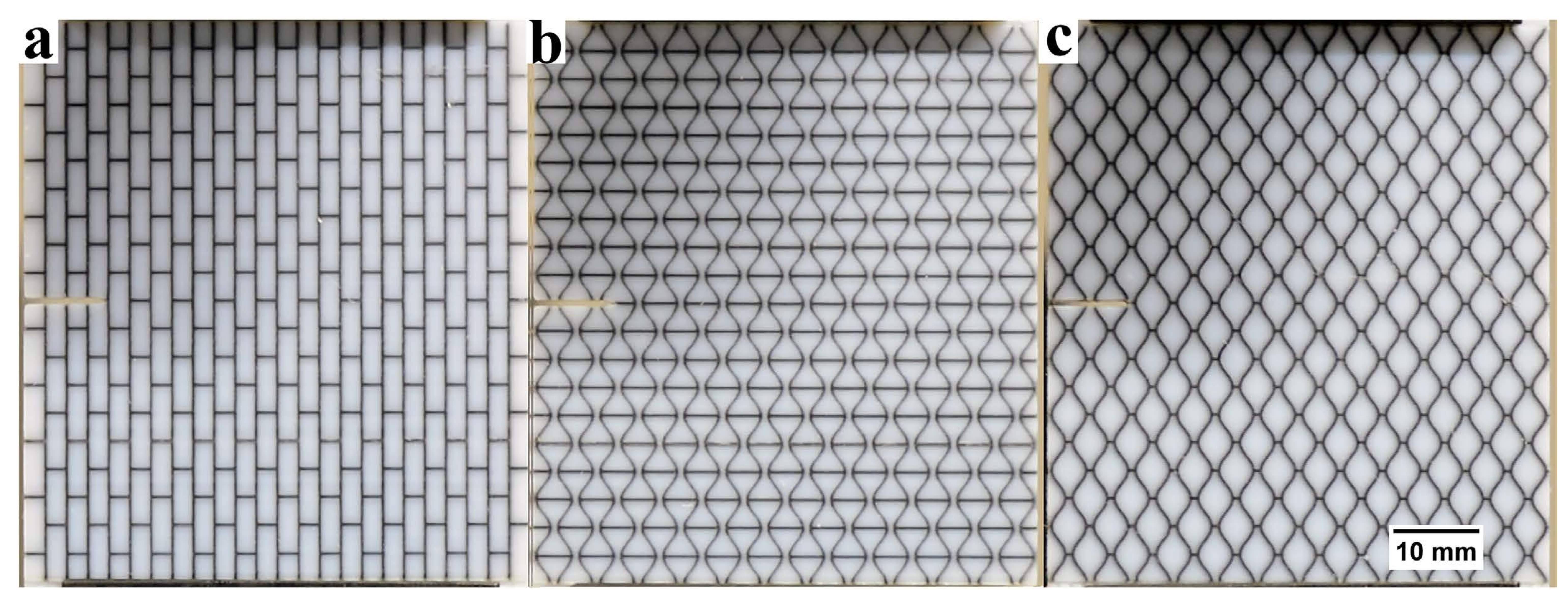
Figure 9- Images of additively manufactured specimens used for mode I fracture testing. (a) Brick-and-mortar sample, representing a simplified nacre structure; (b,c) “hourglass” and “smooth honeycomb” samples [44].
-Sandwich panels using by topologically interlocked elements
A growing demand for materials with improved performance is the driving force for research into innovative materials design, and hybrid materials come to the fore as a promising answer to this demand [2]. Variability of properties and functions of a hybrid is achieved by combining at least two materials with simultaneous shape and scale optimization. Ashby and Bre´chet [2] in their research describe a sandwich structure as an epitome of a hybrid material and an example of ultimate efficiency in design. Owing to their high stiffness and light weight, sandwich panels are extensively used in aerospace and automobile industries where weight-saving is crucial. The concept of topological interlocking provides a promising avenue for designing sandwich structures.
In 2013, A. Molotnikov et al. [45] have presented a novel approach for designing lightweight sandwich structures by using an assembly of topologically interlocked building blocks as a core of the sandwich. The results of a study in three point bending tests demonstrate a significant increase in maximum deflection before failure and absorbed energy over that of a sandwich with a monolithic core. The investigation has shown that by segmenting a monolithic sandwich core made from polyurethane into an assembly of interlocked osteomorphic blocks a remarkable increase in the deflection at failure and in the energy absorption capability can be achieved. The concurrent reduction in flexural modulus is not very dramatic and can be considered as an acceptable trade-off in the overall balance of properties of the sandwich panels[45]. Figure 10 reveals the sandwich panel with an assembly of osteomorphic block as its core undergo different deformation.
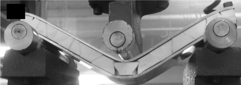
Figure 10- Failure of the core of a sandwich panel [45].
2.3.3. Enhancement of sound absorption
The concept of topological interlocking provides an interesting avenue for improving the sound absorption properties of known materials. M. Carlesso et al. in 2011 [46] have presented a novel approach for combating noise pollution by segmentation of monolithic plates into an assembly of topologically interlocked building blocks. The results of a study of the sound absorption in such segmented structures demonstrate a spectacular increase in the sound absorption coefficient over that in the original material (dental stone GC Fujirock). Measurements of the airflow resistance confirm the primary role of segmentation in imparting high sound absorption capability to the material, notably in the audible frequency range. In particular, it is of interest to study the dependence of the absorption peak frequency on the size of the osteomorphic blocks. Such dependence would make it possible to achieve enhanced sound absorption in a broad frequency range, e.g. by using stacked assemblies with different block sizes. While the interest in this problem has triggered by the need to increase the sound absorption of the ceramic tiles used for thermal insulation of gas turbine engines, a much broader range of applications is envisaged [46].
2.4. Impact behaviour of concrete
Concrete has been widely used over many years by military and civil engineers in the design and construction. These structures might be subjected to extreme loadings during their service life, such as blast and explosive loading which could produce an overload much greater than the design load of a structure in a very short period of time. This may result in severe damage to the reinforced concrete structure and cause tremendous casualties and property loss. In particular, for strategically important infrastructure such as government and defence buildings, a high level of blast resistance is required due to the increasing risk of terrorist attacks. In addition, industrial explosion is another cause of such accidents. Therefore, it is of great significance to investigate the structural response of reinforced concrete structures to blast loading so as to provide reliable design guidelines to resist blast loads.
The analysis of structures made of brittle materials, such as concrete under blast loading is a very complex issue. Short duration and high magnitude loading can significantly influence the structural response. The frequencies of explosive loads can be much higher than that of the conventional loads, and short duration dynamic loads exhibit strong spatial and time variations, leading to sharp stress gradients in the structures and a varying strain rate for the duration of the analysis [47]. A few experimental studies on the reinforced concrete panels subjected to blast loading have been reported, such as the blast loading trials on simply supported reinforced concrete panels with openings conducted by Mays et al. [48], the test of the clamped reinforced concrete panels subjected to explosive loading carried out by Razaqpur et al. [49], the blast test on a simply supported one-way reinforced concrete panel done by Sun [50], the air blast tests on steel fibre reinforced concrete panels with various fibre types and boundary conditions carried out by Lok and Xiao [51]. In addition, the blast responses of sandwich panels consisting of mild steel face plates and aluminium honeycomb cores were investigated by Chi et al. [52].
However, full scale experimental test is usually costly and time consuming. A simplified single degree of freedom (SDOF) system has been widely used to predict the dynamic response of a structural member under blast loads. Naito and Wheaton [53] used a combination of a static finite element analysis and an equivalent SDOF dynamic analysis to determine the response of a reinforced concrete shear wall under blast loading. A corrugated stainless steel wall subjected to blast loading was analysed by Fallah and Louca [54] using the SDOF model with the resistance curve extracted from finite element analysis. In Low and Hao’s study [55], a reinforced concrete slab was simplified to an equivalent SDOF system, and the peak dynamic response of the SDOF system to blast loads was solved dynamically. The response of a SDOF idealised model is an approximation of the displacement at some important point in a real structure. Parameters used to describe a SDOF model are converted from the original continuous structure by utilising an admissible function and application of the principle of virtual displacements [54]. Although the SDOF model has been proven to yield satisfactory overall structural response, the predictions are found to be very conservative [56], moreover, it cannot give an accurate indication of local damage of a structural component [57, 58].
In order to obtain more accurate predictions of structural behaviour of reinforced concrete structures and structural members under blast loading and avoid large numbers of repetitive experimental tests, many efforts have been made in recent years to the development of reliable numerical techniques. So far, the commercial numerical hydrocodes such as LS-DYNA and AUTODYN have been used in several studies. A 3D finite element model was proposed by Xu and Lu [47] using LS-DYNA for modelling of reinforced concrete plates subjected to blast loading, in which solid elements were used for modelling the concrete while the effect of reinforcements on the reinforced concrete behaviour was simulated by a mixture model in which the bulk modulus was contributed by both concrete and reinforcements. Different degrees of damage in concrete were investigated, and empirical equations were proposed in their study as spallation criteria. The blast resistance of reinforced concrete slabs was also investigated by Nam et al. [59] using LS-DYNA. Solid and beam elements with rate dependant material models were used for modelling the concrete and reinforcing bars respectively, and the mid-span displacement and the maximum strain of the concrete slabs were reported. Pereira et al. [60] investigated the blast resistance of cracked steel structures repaired with carbon fibre-reinforced polymer (CFRP) composite patch using LS-DYNA. The steel box was modelled using quadratic shell elements, and CFRP patch was modelled with a layered thin-shell element. The effects of patch thickness, patch size and laminate design were reported in their study [60]. The response of a reinforced concrete slab to blast loading was estimated by Zhou et al. [58] using AUTODYN, where the blast wave propagation was modelled in a 2D simulation, and then the results obtained from the 2D calculation were remapped to a 3D model to consider the interaction between the blast wave and the concrete slab. A dynamic material model for concrete was modified and employed in their numerical model. The blast pressure and the damage on concrete slabs were predicted. Luccioni et al. [61] simulated the structural collapse of a reinforced concrete building under blast loads using AUTODYN. Instead of modelling the concrete and reinforcements separately, a homogenised elasto-plastic material model that considered the collaboration of the reinforcements in tension was used in their study to simulate the behaviour of reinforced concrete components [62].
However one of the great research interests for protection is the plates subjected to impact and wide range of research has been reported on various types of system subjected to ballistic impact [63-68]. Very limited experimental and numerical studies have been conducted in understanding the dynamic characteristics of these novel structures subjected to low velocity impact. In 2012, drop tower tests have been carried out to specify the mechanical behaviour of the topologically interlocked material (TIM) created of identical tetrahedral unit elements made of intrinsically brittle base material by Khandelwall et al. [31]. Numerical model of same TIM assembly with Khandelwall et al. experiments [31] is studied in 2014 by Y. Feng et al. [39]. Their study numerically has investigated the dynamic responses of TIM under constant velocity and projectile impact loading with finite element method. The FEA model is calibrated with published experimental data. The resistances of TIM under constant velocity and projectile impact were examined. [39]. In Figure 11, the residual deformations of the TIM assemblies after indention are shown for the experiment (Figure 11a [31]), and the model simulation ( Figure 11b). A good qualitative agreement is obtained.
(a) 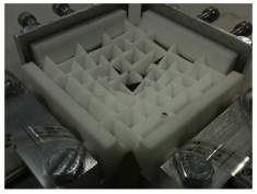 (b)
(b) 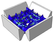
Figure 11- Deformed configurations of TIM assemblies after loading: (a) Experimental observation [31], (b) Model prediction with colour contours depicting the residual stress state as characterized by the von Mises equivalent stress [39].
Cite This Work
To export a reference to this article please select a referencing stye below:
Related Services
View all


Related Content
All TagsContent relating to: "Building Materials"
Building materials refers to any material that is used for construction. Many different natural materials were used historically for building such as wood, clay, stone etc. but the material most commonly used in construction is now concrete.
Related Articles

DMCA / Removal Request
If you are the original writer of this dissertation and no longer wish to have your work published on the UKDiss.com website then please: