Network Infrastructure Design with Segmentation and Traffic Management
Info: 11886 words (48 pages) Dissertation
Published: 8th Sep 2021
Contents
Explain network segmentation and basic traffic management concepts
Describe routing concepts at a theoretical level
Compare and contrast methods of routing and routing protocol
Describe basic routing concepts (including packet forwarding and router lookup)
Recommend a routing protocol and justify your recommendation.
Recommend a solution for marketing to have restricted access to R&D and justify your recommendation.
Introduction
This document has two main parts including the network design and the explanation based on the design intended for the audience who is not technical. In the network design, the client wants a design for the network infrastructure and there is IT support team who will have the authority to manage all the servers, user and email accounts and folder permission. In addition, the connection in each site have high-speed connection that restricts the access for internet only. On the management team who were not technical person, providing a document for their reference for the network diagram effective description for the network technology and concepts.
Objectives
The objectives required to learn at the end of the assessment:
- To learn routing concepts at theoretical level
- To understand network segmentation and basic traffic management concepts
- To learn basic routing (including packet forwarding and router lookup)
- To distinguish the methods of routing and routing protocols
Overview
The client, ZipTech Manufacturing Ltd, is the company that caters services for aerospace industry based on the production of custom water and airtight containers. The company have two location which the main office is in the Christchurch and offices in American states such as Texas and Washington. The company wants to ensure that their new and specialized product is effective to secure and maintain the data.
Summary of the Tasks
The task is to create a network design with relevance to Cisco equipment and includes diagram and explanation of proposal for maintaining the security and giving the privilege for the IT Support team to remotely manage servers at each site. In addition, there were audience who are not network engineers in the management team of the Ziptech. In able to provide information for those people, document the common network technologies and provide explanation for the following concepts and include some recommendations in design. For the first part of designing the network, you can see the table below illustrating the company structure of Ziptech. The second part is for the audience providing layman’s term in some explanation of the concepts and recommendation.
COMPANY STRUCTURE
The department are staffed as follows:
| Department | Location | No. of Users | Requirement | Restriction |
| R&D | In industrial park on the outskirts of Christchurch | 10 | Servers are managed by IT Support team | Staffs not allowed to access internet connection |
| Marketing | 4th Floor Christchurch CBD | 5 | Users have internet access | One user has restricted access via VPN |
| Shipping | Different industrial park on the outskirts of Christchurch | 3 | Have high-speed internet connection
Access to the accounts department network |
|
| Accounts | Another office in the Christchurch CBD | 3 | Have high-speed internet connection access to shipping and marketing | |
| Sales | American states (Texas and Washington) | 4 | Have internet access and access to shipping and accounts | |
| IT Support | Share the same office space in the marketing department | 5 | One team member works full-time on the R&D network |
Client Concerns
| Department | Concern |
| R&D, marketing, shipping and accounts/IT Support | Different Locations |
| Texas and Washington |
|
| Marketing |
|
| IT Support | remotely and securely manage servers on each network |
These are the questions that needs to answer for the audience to understand the network design and deliver information for decision making in the company. The questions are:
- Explain network segmentation and basic traffic management concepts
- Describe routing concepts at a theoretical level.
- Compare and contrast methods of routing and routing protocols.
- Describe basic routing concepts (including packet forwarding and router lookup process)
- Recommend a routing protocol and justify your recommendation.
- Recommend a solution for marketing to have restricted access to R&D and justify your recommendation.
- All information sources should be properly referenced.
TASKS ANSWERS
REQUIREMENTS
| Department | Location | No. of Users | Requirement | Restriction |
| R&D | In industrial park on the outskirts of Christchurch | 10 | Servers are managed by IT Support team | Staffs not allowed to access internet connection |
| Marketing | 4th Floor Christchurch CBD | 5 | Users have internet access | One user has restricted access via VPN to R&D Server |
| Shipping | Different industrial park on the outskirts of Christchurch | 3 | Have high-speed internet connection
Access to the accounts department network |
|
| Accounts | Another office in the Christchurch CBD | 3 | Have high-speed internet connection access to shipping and marketing | |
| Sales | American states (Texas and Washington) | 4 | Have internet access and access to shipping and accounts | |
| IT Support | Share the same office space in the marketing department | 5 | One team member works full-time on the R&D network |
DIAGRAM
LEGENDS
|
DEPARTMENT |
 |
 |
 |
 |
 |
 |
 |
|
LINK |
 |
 |
 |
 |
 |
 |
Diagram Requirements
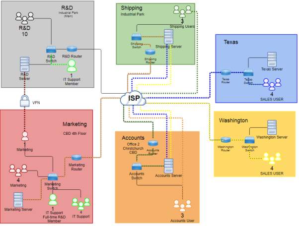
Based on the diagram designed, it uses devices such as a router, switch and server to build site-to-site connection in different location specifically in Christchurch and some American State like Texas and Washington. The explanation will be provided to know what is been used building the diagram of ZipTech company. To create the example, specific device needs to be mentioned based on (Cisco System Inc., 2005) which includes:
- Router – Cisco 2600 series
- Switch – Catalyst 2940, 2950 or 2970
Both devices can carry traffic from VLAN in a way trunking protocol or access. However, there are two ways in which trunking can be implemented like the ISL which the Cisco proprietary for switches such as 2940 or 2950 series and 802.1q which IEEE standard. In addition, the right Cisco IOS for the devices are important because for the configuration of the device to accept some added features or changes for updated IOS.
Router – the use of this device for every department creates virtual implementation for multiple links connecting to the switch in able to have single link for the interface of the router. The use of 802.1q trunk link to place sub-interface for each VLANs creates logical interface which makes the multiple VLANs can travel interface in a single link and limit physical ports required. For clarifications, trunk contains multiple VLANs aggregates in a single link and the trunk commonly use the method of IEEE 802.1q standard.
A sub-interface relates to the VLAN of the switch connecting to the router which creates logical interface from physical interface. This configuration makes multiple interface turn to a single interface but the router must support trunking method like 802.1q as well as the configuration in the switch.
Switch – the use of this device has the relationship connecting to the router to create VLANs and implement the router on a stick network to the router. Switch creates VLANs such as access VLANs to the ports at the same time the trunk connection to create single logical interface out of multiple physical interface to reduce the traffic congestion of VLANs. In addition, some security option can provide by this device which the port itself have specific restrictions and violation for the incoming ports or MAC Address.
VLAN – the use of logical subnetwork in the design manages the broadcast domain of devices per department or different LAN segment. It segments the ports in which it will be assigned providing better management of devices. In addition, it creates a logical group to isolate the network in the data link layer (Layer 2) instead the physical connection.
IEEE 802.1
Dot1q only appears when the configuration of router and switch tag VLANs to implement the router on a stick. Tagging relates with the IEEE 802.1q standard for VLAN ID to know the destination of the VLAN sending to Ethernet frames but the frame is removed when it reaches the destination. (TelecomWorld 101, n.d.)
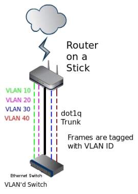
Router on a stick Frame tagging on dot1q Trunk(TelecomWorld 101, n.d.)
The image above illustrates the VLAN 10, 20, 30, and 40 tag their VLAN ID to the switches as if the VLANs will dot1q removed when it goes to the access device. Router on a stick network will still exist if the interface and traverse into the routers and switches. All tagged VLANs create a single physical link between the switch and the router. (TelecomWorld 101 )
There are two other VLANs which is needed to associate the dot1q network by (TelecomWorld 101 ):
- Management VLAN – it is a VLAN where it used for security purposes specially for remote another connected device. This VLAN is separate from data traffic and manage address for different devices for configuration and administration remotely.
Same Configuration:
Global Configuration
(config)#intvlannumber
(config)# ip address (address) (mask)
- Native VLAN – it is process where VLAN is not tagged whereas the VLAN is not changed ever it is transmitted at the same time VLAN 1 is a default VLAN that is also a native VLAN. If you do not configure native VLAN, the VLAN is placed in VLAN 1 as untagged VLAN. For best practice, native VLAN must be in a separate VLAN for security purposes rather than the default VLAN 1.
Same Configuration:
Global Configuration
(config)# vlannumber
(config)# name Native
Interface command
(config)#interface (port)
(config-if) #switchport mode trunk
(config-if) #switchport trunk native vlan (number)
Here is the trunk configuration example for the routers and switch by (TelecomWorld 101 ):
- Switch Configuration –port configuration connecting to the router as a dot1q trunk.
(config)#interface fast Ethernet[X/X] // port of the switch connects to the router
(config-if) #switchport trunk encapsulation dot1q //optional, indicates trunk protocol
(config-if) #switchport mode trunk //configures port as a trunk
(config-if) #switchport trunk native vlan 99 //VLAN ID 99 as the native VLAN for the trunk
- Router Configuration –configuresub interface for each VLAN on the physical Ethernet port. The sub interfacewillbe the default gateway for the VLAN of the end devices. For example, configure VLAN 10 sub interface, and configure the other VLAN as well for VLAN 20, 30, 40:
(config)#interface fast Ethernet[X/X] //this is the physical interface of the router needs to turn on
(config-if) #no shutdown //turn on the interface
(config-subif) #interface fa0/0.10 //sub interfacerelates to VLAN 10
(config-subif) #encapsulation dot1q 10 //encapsulate IEEE802.1Q tagging of frames to VLAN 10
(config-subif) #ip address 192.168.10.1 255.255.255.0 //IP address to the sub interface
Access Ports
Access ports transmit data from a specific VLAN particularly in the end devices. The end devices have its assigned VLAN to have segmentation in which group it belongs to manage the broadcast domain. It carries single VLAN corresponds to its interface but if the port is not tagged in the VLAN, it is in the default VLAN 1 of the device.
Sample configuration:
(config)#interface fast Ethernet [interface number]
(config-if) #switchport mode access
(config-if) # switchport access vlan [vlan number]
Port Security
Port security is a feature of the switch to control traffic particularly for the incoming unknown access or MAC Address which manages by an administrator. In best practices, the unused port must be secured to restrict unknown user to access in the end devices.
To enable the port security in the switch by (stretch, 2010):
(config)# interface fast Ethernet [X/X]
(config-if) # switchport port-security
Putting some port security violation to secure the interface for incoming unknown users or limiting the ingress MAC Address. Here is the configuration:
(config)# interface fast Ethernet [X/X]
(config-if) # switchport port-security violation restrict
(config-if) # switchport port-security violation shutdown
For the MAC Address:
(config)# interface fast Ethernet [X/X]
(config-if)#switchport port-security maximum 3
Set Maximum MAC Address count for data and voice VLANs
(config-if) # switchport port-security maximum 1 vlan access
(config-if) # switchport port-security maximum 1 vlan voice
Static configuration for allowing MAC Address or enabling the “sticky” to learn MAC Address dynamically
(config-if) # switchport port-security mac-address 001b.d41b.a4d8 vlan access
(config-if) # switchport port-security mac-address sticky
Network Addressing
Most of the department use the Class C IP Address range which provides the network hosts per network of 254 together with the use of Class C private network of 192.168.0.0 to 192.168.255.255. However, it uses the /27 subnet mask to utilize the use of the IP address on the required number of hosts. As for the ZipTech company hosts, the /27 CIDR (Classless Inter-Domain Routing) fits all of the hosts which includes 30 number of hosts per location of the network.
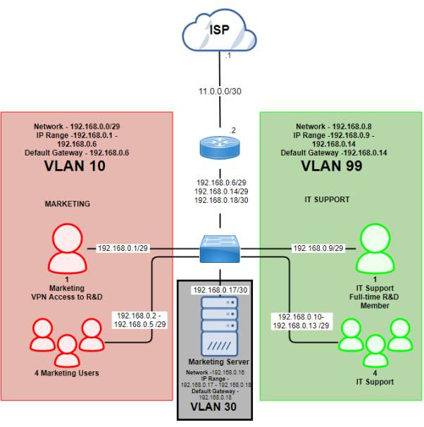
CBD 4th Floor (192.168.0.0/27)
| Subnet Name | No. of Host | VLAN | Address | Subnet Mask | Assignable Range | Broadcast |
| CBD 4th Floor (Marketing User) | 5 | 10 | 192.168.0.0/29 | 255.255.255.248 | 192.168.0.1 – 192.168.0.6 | 255.255.255.248 |
| CBD 4th Floor (IT Support) | 5 | 99 | 192.168.0.8/29 | 255.255.255.248 | 192.168.0.9 – 192.168.0.14 | 255.255.255.248 |
| CBD 4th Floor (Server) | 1 | 30 | 192.168.0.16/30 | 255.255.255.252 | 192.168.0.17 – 192.168.0.18 | 255.255.255.252 |
CBD 4th Floor – Public IP
| Subnet Name | No. of Host | Address | Subnet Mask | Assignable Range | Broadcast |
| Public IP (CBD4) | 2 | 11.0.0.0/30 | 255.255.255.252 | 11.0.0.1 – 11.0.0.2 | 11.0.0.3 |
Marketing CBD 4th Floor Diagram
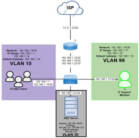
Industrial Park (192.168.1.0/27)
| Subnet Name | No. of Host | VLAN | Address | Dec Mask | Assignable Range | Broadcast |
| Industrial Park (R&D Users) | 10 | 10 | 192.168.1.0/28 | 255.255.255.240 | 192.168.1.1 – 192.168.1.14 | 192.168.1.15 |
| Industrial Park (IT Support) | 1 | 99 | 192.168.1.16/30 | 255.255.255.252 | 192.168.1.17 – 192.168.1.18 | 192.168.1.19 |
| Industrial Park (Server) | 1 | 30 | 192.168.1.20/30 | 255.255.255.252 | 192.168.1.21 – 192.168.1.22 | 192.168.1.23 |
Industrial Park – Public IP
| Subnet Name | No. of Host | Address | Dec Mask | Assignable Range | Broadcast |
| Public IP (IP) | 2 | 11.0.1.0/30 | 255.255.255.252 | 11.0.1.1 – 11.0.1.2 | 11.0.1.3 |
Industrial Park Diagram
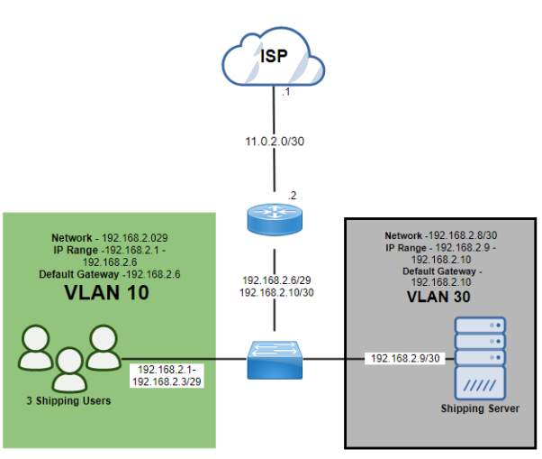
Industrial Park 2 (192.168.2.0/27)
| Subnet Name | No. of Host | VLAN | Address | Subnet Mask | Assignable Range | Broadcast |
| Industrial Park 2 (Shipping Users) | 3 | 10 | 192.168.2.0/29 | 255.255.255.248 | 192.168.2.1 – 192.168.2.6 | 192.168.2.7 |
| Industrial Park 2 (Server) | 1 | 30 | 192.168.2.8/30 | 255.255.255.252 | 192.168.2.9 – 192.168.2.10 | 192.168.2.11 |
Industrial Park 2 – Public IP
| Subnet Name | No. of Host | Address | Dec Mask | Assignable Range | Broadcast |
| Public IP (IP2) | 2 | 11.0.2.0 | 255.255.255.252 | 11.0.2.1 – 11.0.2.2 | 11.0.2.3 |
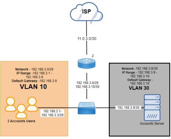
CBD 2 (192.168.3.0/27)
| Subnet Name | No. of Host | VLAN | Address | Subnet Mask | Assignable Range | Broadcast |
| CBD 2 (Accounts Users) | 3 | 10 | 192.168.3.0/29 | 255.255.255.248 | 192.168.3.1 – 192.168.3.6 | 192.168.3.7 |
| CBD 2 (Server) | 1 | 30 | 192.168.3.8/30 | 255.255.255.252 | 192.168.3.9 – 192.168.3.10 | 192.168.3.11 |
CBD 2- Public IP
| Subnet Name | No. of Host | Address | Dec Mask | Assignable Range | Broadcast |
| Public IP (CBD2) | 2 | 11.0.3.0 | 255.255.255.252 | 11.0.3.1 – 11.3.0.2 | 11.0.3.3 |
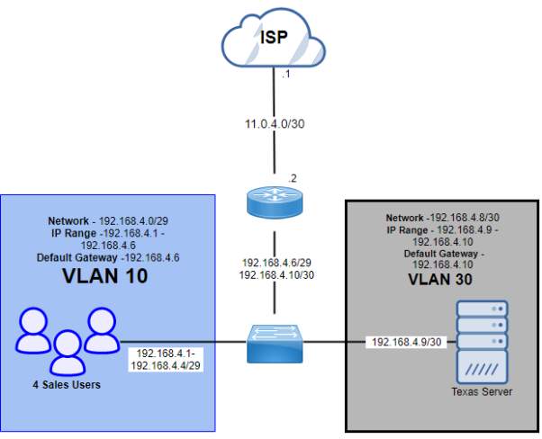
Texas (192.168.4.0/27)
| Subnet Name | No. of Host | VLAN | Address | Subnet Mask | Assignable Range | Broadcast |
| Texas (Sales Users) | 4 | 10 | 192.168.4.0/29 | 255.255.255.248 | 192.168.4.1 – 192.168.4.6 | 192.168.4.7 |
| Texas (Server) | 1 | 30 | 192.168.4.8/30 | 255.255.255.252 | 192.168.4.9 – 192.168.4.10 | 192.168.4.11 |
Texas – Public IP
| Subnet Name | No. of Host | Address | Dec Mask | Assignable Range | Broadcast |
| Public IP (Texas) | 2 | 11.0.4.0 | 255.255.255.252 | 11.0.4.1 – 11.0.4.2 | 11.0.4.3 |
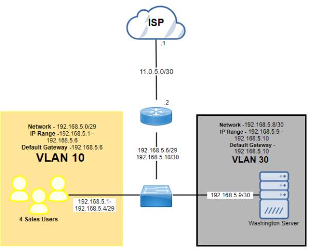
Washington (192.168.5.0/27)
| Subnet Name | No. of Host | VLAN | Address | Subnet Mask | Assignable Range | Broadcast |
| Washington (Sales Users) | 4 | 10 | 192.168.5.0/29 | 255.255.255.248 | 192.168.5.1 – 192.168.5.6 | 192.168.5.7 |
| Washington (Server) | 1 | 30 | 192.168.5.8/30 | 255.255.255.252 | 192.168.5.9 – 192.168.5.10 | 192.168.5.11 |
Washington – Public IP
| Subnet Name | No. of Host | Address | Dec Mask | Assignable Range | Broadcast |
| Public IP (Washington) | 2 | 11.0.5.0 | 255.255.255.252 | 11.0.5.1 – 11.0.5.2 | 11.0.5.3 |
Access requirements and restriction of the network department
| Department | R&D | Marketing | Accounts | Shipping | Texas | Washington |
|
Requirement |
Servers are managed by IT Support team | Users have internet access | Have high-speed internet connection access to shipping and marketing | Have high-speed internet connection
Access to the accounts department network |
Have internet access and access to shipping and accounts | Have internet access and access to shipping and accounts |
| Restriction | Staffs not allowed to access internet connection | One user has restricted access via VPN |
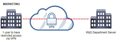
R&D and Marketing
Marketing has one user has restricted access via VPN to the server of R&D
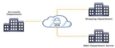
Accounts Department to Shipping and Marketing Department
Accounts have high speed internet connection to access to shipping and marketing
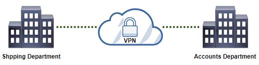
Shipping Department to Accounts Department
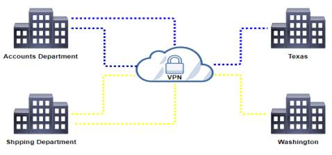
Texas and Washington to access Shipping and Accounts department in Christchurch
Access list –there are four types of ACL which supports the switch to control the filtering of network traffic together with security measures for the interface or IP Protocols which includes Router ACL, Port ACL, VLAN ACL and MAC ACL cited by (Bhaiji, 2008).
Router ACL – this is similar to Cisco IOS Assess lists which divided into two types(Antoniou, 2008):
Standard ACL – a standard form which you only filter the source IP address in which you allow or deny the traffic from the target IP address.
Extended ACL–an advanced form where you filter the preferred traffic based on the source/destination IP address, protocol (TCP/UDP), port number (ftp, telnet) and supplementary parameters.
Port ACL – the process is the same with Cisco IOS access list but it supports physical interface specially the inbound traffic. It assesses the ACLs which relates to the given interface whether to allow or deny the packet forwarding. In addition, Port ACL filter traffic based on interface as well the MAC address access lists.
VLAN ACL –commonly known as VLAN map which it filters the VLAN routed based on the in or out traffic of the switches. The process undergoes in the hardware as the VLAN ACL lookup the direction of traffic traversing the device.
MAC ACL –commonly known as Ethernet ACL because it uses named MAC extended ACL which includes the command mac access-list extended instead of IP Address. This access-lists only support inbound traffic filtering which applied in the layer 2 interface using mac access-group [acl-name] in command.
In this design, Router ACL specifically the extended ACL is used because for more complex configuration of filtering the traffic based on the required Internet access of users per department. The company wants a specific people that has the only access for the Internet particularly the IT Support Team which manages all the servers per location. The IT Support Team provide security and maintenance of accessing the servers as well as in different locations. The VLAN ACL can possibly use because this will help the network to filter the required VLAN to access the preferred destination.
Sample configuration of Extended Access list
(config)# ip access-list extended [acl_name]
(config-ext-nacl)# permit tcp any any eq www //permitting to access to the web traffic
(config-ext-nacl)# permit tcp host [ip_address] any eq ssh //adding access using the SSH
(config-ext-nacl)# exit
The following commands activate the access list for an interface:
(config)# interface gigabitethernet [X/X]
(config-if)# ip access-group [acl_name] in
(config-if)# exit
Site-to-site IPSEC VPN Tunnel – a security technology used in by each location to virtually access the private network that provides encryption and reliable connection over the Internet using the GRE (Generic Routing Encapsulation) tunnels to manage VPN tunnels between the routers. Basically, it was developed through remote access by the users and offices managing the application of the company securely but what it must provide authentication methods to enter such as username, passwords and any other forms of credentials. (Rouse, Virtual Private Network (VPN), 2016) As the VPN operation shows that the public IP address used can access through the private network securely.
The IPSec VPN Tunnel is considered for security technology to have secure connection when accessing different sites via the Internet. The GRE tunnel will manage the connection of VPN to remote to different sites. All the departments are in the private network so the IPSec VPN is essential when passing through the Internet which provides additional security such as credential to enter the required username and password when accessing the network. As mentioned by (Tyson & Crawford), this gives an advantage for the company that will use VPN because it is cost-efficient and reliable transaction.
Requirement to configure to Site-to-site IPSec VPN Tunnel:
- IPSec Phase 1 (ISAKMP Policy)
- IPSec Phase 2 (Transform Set)
- Extended ACL
- Crypto Map
- Crypto Map to the outgoing interface
- VPN Traffic from the NAT
- Verification
- Test the VPN using ping
- show crypto isakmp sa
- show crypto ipsec sa
- show crypto session
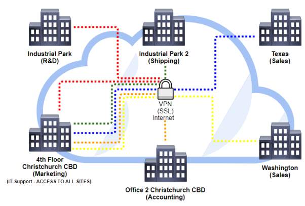
Proposed security to access site-to-site remotely is SSL/TLS VPN
| Location | Link |
| Industrial Park (R&D) |  |
| Industrial Park 2 (Shipping) | |
| Office 2 Christchurch CBD (Accounting) | |
| Texas (Sales) | |
| Washington (Sales) | |
SSL is the VPN protocol proposed used in the Internet environment which provides the security of the transmission over TCP across the application using authentication of username and password. In addition, HTTP, or HTTPS application also managed by the SSL to communicate effectively with the confidentiality and authenticated code. (Viega, Messier, & Chandra, 2002)
There are areas where SSL protocol gives to have security between the connection and the application which includes the following: encryption of the connection with hides all the information, proven identity authentication and authorization which has the legal certificate to access, and integrity checking that will maintain the connection and securing the data. (Viega, Messier, & Chandra, 2002)
This protocol performs effective security for the information between the communication of the application and the client/server users. In addition, huge amount of data should properly configure and protected with helpful tools for the administrator and the system to operate efficiently. (McKinley, n.d.)
Part 2
This second part of the document consists of terms that will able to understand the network concepts with explanation and recommendation based on the network design. The network design has some network segmentation, traffic management, routing concepts and security. These are the questions for this second part of the document:
Explain network segmentation and basic traffic management concepts
Network segmentation consists of logical group of devices connected to the local area network and share its resources to build the distribution of segment. By the term logical, it means that it is virtually used which performed by routers, switch segmentation or VLAN[1] (Virtual LAN). Devices like routers and switches to segment a network either logically using the VLANs or physically with separation of subnetworks based on the design.
Devices connected a LAN[2] needs to have network segment because this will manage the unnecessary traffic of data traversing between devices creating a single broadcast domain and collision domain. A broadcast domain is, as the name states, the collection of devices in which broadcasts in the network segment. On the other hand, collision domain is a network scenario which devices send packets simultaneously causing the network segment to have collision and packets[3] will not be delivered. A lot of devices traverse packets simultaneously which creates collision and traffic congestion between hosts and to prevent this, it needs segmentation to break down into small parts of networks to be organized and perform well. (Test King, n.d.)
Another aspect to consider is subnetting or segmenting the number of hosts required in the department. For example, there are different department with different traffic regardless who has the large amount of traffic or least, the departments are not segmented properly. Traffic congestion[4] will take place because the traffic does not have the allocated traffic for that department, which means a large traffic can move into a single department only and not in the other departments. One solution to resolve or minimize the problem is segmentation which provides network isolation or congestion, balanced traffic and bandwidth allocation, and the privilege to restrict hardware or software issues that cannot affect the whole network. (Test King, n.d.)
There are certain devices needed to perform segmentation in the network such as routers and switches. These devices have its own characteristics limiting the congestion of packets between devices and isolation of network to have priority in the traffic flow.
ROUTER
Routers provide routing operation which in the Layer 3 (Network Layer) of the OSI model[5]. It routes data packet to transmit to different devices based on the IP Address[6]. Basically, the router features are giving logical addressing of the node and network segment of the network. By the end of each node[7], routing protocol is used together with the addressing information to encapsulate data into packets to connect through an internetwork.
The role of the router in segmentation is the ports of the router makes the separation of segment and collision domain. In short, routers break down the broadcast domain which maintain the separation from the other segment in contrast to switch still in the same broadcast domain. In addition, sending data in the segment to the destination will only receive the broadcast message but not in the same network. There are attributes such as path selection, filtering, and switching of the router that uses logical addressing and access lists. Remoting the network needs routing table by the router to use its path selection[8] and internetworking[9].
SWITCH
The switch is also part of the data link layer (Layer 2 – OSI Model) which acts some of the features as bridges. It uses the hardware based on MAC Address [10]which forward and flood the traffic which it learns by the device, and the destination of the port responds to the request of the source. All the information is stored in a table which the switch learned to transmit to the different devices connected to it.
Switches create multiple collision domain in each port in which the use of Virtual LANs manage the network virtually to break all the connected devices to separate the broadcast domain. Virtual LAN or virtual workgroups provide isolation to all the traffic containing the VLAN at the same time it communicates with the router that selects the best path to segment the network. Further, logical segmentation provides easier management and security to have scalability and maintainability to the network.
Describe routing concepts at a theoretical level
The routing is using the packet which is a data carried in the networking layer to send through networks. Routers main function is to route traffic to your internetwork which has the destination address, remote network for neighbor routes and maintain the routing information. Routing information contains routes stored in routing table to describe the connected networks. It is also a path where routing process takes place to know the best path of each network. To find the best path of the network, the routing table[11] is used to maintain containing the network and routing information.
However, if the network is directly connected, the devices attached to it automatically know the information to get to that network but if the networks are not attached, it must learn how to know the information either static, manually putting the network locations in the routing table or dynamic routing, automatically communicate with neighbor device which the other device has another neighbor information. Using dynamic routing gives automatic update of routing table and inform about the routing changes of all the routers but static routing needs manual updating of changes. As (Osterloh, 2002) cited, the host needs to communicate in the different network it must be configured with the IP address whether statically or dynamically configured to discover by the local router, default gateway[12]. In addition, the outside with its local subnet[13] will provide data forwarding to communicate with the router.
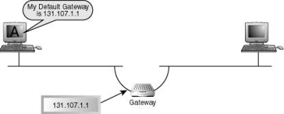
Routers Default Gateway(Osterloh, 2002)
Compare and contrast methods of routing and routing protocol
First of all, for the part one which you design the network of ZipTech company, the network design only uses the routing protocol static routing between the router of each location connecting to the ISP. For example, the marketing department which is in the 4th Floor CBD of Christchurch and the main router of their network is connected to the ISP. Lastly, the ISP is the only one who has the control of routing whether it uses the routing protocol of BGP (Border Gateway Protocol) or MPLS (Multiprotocol Label Switching) to connect different location of Christchurch and American State (Texas and Washington). Further, the explanation below will provide a brief knowledge for the audience to know about the methods of routing and routing protocol.
Here are the three types of methods of routing:
Static Routing – this is the process which manual adding of routes in the routing table
The command used to manually add the static routes to routing table:
ip route [destination_network] [mask]
[next_hop_address or exit interface] [administrative_distance] [permanent]
The following meaning that describes the string:
- ip route – first command used to the static routing
- destination network – network to store in the routing table
- mask – subnet mask representing the IP address used in the network
- next hop address – target network that will receive the packet to remote the network. Exit interface which is directly connected to the network.
- Exit interface – interface link desired
- Administrative distance – selecting of best path corresponds to routing protocol used. Static route administrative distance is 1 while directly connected is 0.
- Permanent – keep the entry in the routing table no matter what happen if it will go down or shutdown
Default Routing–used to send packets in the stub networks[14] which the network has only one exit port in the network not the next hop router. It is known by Cisco that the default route is the gateway of the last resort.
Dynamic Routing–this is the process which makes the routes in the routing table updates automatically but enforce the usage of router CPU and bandwidth of the network. There are two dynamic routing protocol which is the IGP (Interior Gateway Protocol) and EGP (Exterior Gateway Protocol). RIP, OSPF and EIGRP are example of IGP which manages the autonomous system or AS, collection of connected device to the internet protocol uses routing protocol in a single network, while the EGPs such as BGP manage the protocol between different AS.
IGP (Interior Gateway Protocol) has two type of routing protocol which are the distance vector and link-state protocol. These protocols used by companies and organization for their internal network which includes RIP, OSPF and EIGRP. (Cisco Networking Academy, 2014)
Distance Vector – the distance vector identifies the measure of device in which how far the destination located but the routers only know the information of other device based on the reach of the network either the neighbor device or the interface where you want to go. The EIGRP (Enhanced Interior Gateway Protocol) is an advanced protocol which is a distance vector and link state characteristics which is called hybrid.
Link-State – unlike the distance vector, this protocol has the capacity to know all the information of all the devices which has the complete view of the topology. Link-state provides a map which the network can identify the best path locating the destination because the routers updates the information state of the links within its area, in result they have the clear view of network.
EGP (Exterior Gateway Protocol) is the routing protocol used to locate the network using Autonomous Systems, collection of routers within a single administration of the network, which commonly used to exchange route information in the Internet.
Path Vector – unlike the distance vector and link-state, to reach the destination it must know first the path which it will be transmit to determine if it is loop free or not. This protocol ensure that the paths traverse by the routing information is loop free and know the best path because like BGP to calculate paths using some attributes to advertise routes.
The difference of the two protocol is the IGP protocol choose the best path inside the administration of the network which is the ingress that data must cross to reach the destination. However, the EGP protocol manages the routes outside the administration to ensure the connection between two networks at the same time the egress trying to route the data.
There are characteristics of routing protocol that can be compared particularly:
Speed of convergence – the speed of sharing the routing information in different devices in case there will be network failure or changes in routes.
Scalability – it defines the capacity of network to change depending on the requirement or situation of the network to increase or upgrade.
Classful or classless (VLSM) – the appropriate use of routing protocol in the address of the network which supports the use of VLSM (variable length subnet mask) which means summarizing the address of the network.
Resource usage – considering the use of resources such as the hardware, memory and bandwidth utilization to support routing protocols.
Implementation and maintenance – the capacity of knowledge required to handle such implementing effectively the routing to maintain the network.
The table below will show the comparison of routing protocols based on the characteristics by (Cisco Networking Academy, 2014):
| Distance Vector | Link State | ||||||
| RIPv1 | RIPv2 | IGRP | EIGRP | OSPF | IS-IS | BGP | |
| Speed of Convergence | Slow | Slow | Slow | Fast | Fast | Fast | Average |
| Scalability | Small | Small | Small | Large | Large | Large | Large |
| VLSM | No | Yes | No | Yes | Yes | Yes | Yes |
| Resource Usage | Low | Low | Low | Medium | High | High | High |
| Implementation and Maintenance | Simple | Simple | Simple | Complex | Complex | Complex | Complex |
Metric – this the value which represents the routing protocol with the capacity to route in the network. This is also used by different devices for best path to know towards to the destination network which every protocol has their predetermined metric. The examples of metric used are hop count, bandwidth/ delay, and cost.
These are the brief explanation of different routing protocols:
RIP (Routing Information Protocol) – this is the routing protocol uses distance vector because it depends on the hop count of the neighbor devices but with limitation of 15 count. In the smaller network, RIP is very suitable to implement because the speed of the convergence is slow.
IGRP (Interior Gateway Routing Protocol) – a Cisco proprietary routing protocol that uses distance-vector which means the routers must be Cisco and the metric used for this is bandwidth/delay. It has the maximum hop count of 255 which helps larger network to solve problem rather than 15 hops of RIP.
EIGRP (Enhanced Interior Gateway Routing Protocol) – this is also a Cisco proprietary routing protocol but have the capability to become link-state and distance-vector. The performance of the protocol has rapid convergence and loop-free topology.
OSPF (Open Shortest Path First) – this protocol is an open standard routing protocol which uses the link-state protocol. In short, it calculates the best path of the network advertising routing information in its topology database to create adjacencies between the devices.
BGP (Border Gateway Protocol) – this protocol uses advanced distance vector called path vector to exchange network using the AS and lists of attributes to reach the destination network. BGP is commonly used in the Internet to connect to ISPs.
The table will show the summarize comparison of routing protocol by (Balchunas, 2007):
| RIPv1 | RIPv2 | IGRP | EIGRP | OSPF | IS-IS | BGP | |
| Interior/
Exterior |
Interior | Interior | Interior | Interior | Interior | Interior | Exterior |
| Type | Distance Vector | Distance Vector | Distance Vector | Hybrid | Link-state | Link-state | Path Vector |
| Default Metric | Hop count | Hop count | Bandwidth/
Delay |
Bandwidth/
Delay |
Cost | Cost | Multiple Attribute |
| Administrative Distance | 120 | 120 | 100 | 90 (internal)
170 (external) |
110 | 115 | 20(external)
220(internal |
| Algorithm | Bellman-Ford | Bellman-Ford | Bellman-Ford | DUAL | Dijkstra | Dijkstra | Best Path Algorithm |
Algorithm – this is the operation which main function is to know and calculate to determine the best path of routing protocol locating the destination. In addition, this is the way the protocols make the network solve some issues like network loops and ability to converge. There are different types of algorithm used by the routing protocol such as the Bellman-Ford, DUAL and Dijkstra.
Distance Vector – RIP and IGRP mostly used the Bellman-Ford algorithm exchange routing information to prevent routing loops which is directly connected to the neighbors. In addition, it calculates the shortest path with the help of vertices of the graphs. As (Tammaro, 2013) cited, EIGRP uses DUAL (Diffusing Update Algorithm) which calculate paths to prevent the routing loops and with the convergence of routing information for the network.
Link-state- OSPF and IS-IS protocol used the Dijkstra algorithm which helps to calculate the shortest path as the name implies. The main function of the algorithm for the routing protocol is to advertise information about the routes of the neighbors, nodes or traffic to identify the possible calculation to have the shortest path towards the destination.
Describe basic routing concepts (including packet forwarding and router lookup)
Routing is the process where it uses device such as router to find the best path of the network and transporting data across Internet. There are methods which routing concepts is applied such packet forwarding and the process of router to examine routes provide its best match for the destination.
There are methods where you can transfer the packets to share information between the source and destination interface using the systems in the network such as the packet forwarding. There are three methods of packet forwarding namely packet switching, fast switching and Cisco Express Forwarding (CEF).
Packet Forwarding – it is considered as packet switching because the packets traverse to find the outgoing interface and it uses packet switching. The switching is using the packet recorded in the table during the switching which requires forwarding decision by the device CPU. Fast switching is another process switching that uses CPU required by the router for caching in the table. In addition, packet switching involves the consistency of packet to reach the destination in a complete and not changing manner. As mentioned for some routing protocols, they use its own algorithm to process the goal to have the best path reaching the destination network.
Below are the three techniques of packet forwarding to share information for the system on the network by (Learning Certification, n.d.):
- Packet Switching – this method requires the interrupt handler which means that the packet is received by the destination interface of the device and recognized by the Layer 3 (Network Layer of OSI Model) which known by the Layer 2 (Data Link Layer of OSI Model). It is like a queue of packets to process by the packet forwarding of the Cisco IOS, which is the software of the hardware of Cisco devices.
- Fast Switching – this method uses also the interrupt handler but in a different way of processing because the cache, a collection of data, create a process to locate the next hop or outgoing interface of the device. In addition, it uses the processor of the device to provide the forwarding process to different devices reaching the destination.
- Cisco Express Forwarding (CEF) – this method uses a table to calculate the traverse operation done by the packets to the device called the Routing Information Base (RIB) and Forwarding Information Base (FIB) table. This will create a table called, deterministic table as cited by (Learning Certification, n.d.) which is the combination of RIB and FIB to adjacency information.
In a nutshell, packet forwarding makes the process through the decision of the router to connect and communicate all the possible components (e.g. packets, layer 2 and layer 3 protocol) effectively in the network. However, the requirement of the process needs to meet accurately to implement in the large scale of network.
The routing process requires several steps that the hardware should match to the routing process required which includes the following based on (Learning Certification, n.d.):
- Step 1 – The device or the hardware finds the destination address to examine using the packet forwarding
- Step 2 – If the device finds the address then the packet uses packets forwarding to proceed to the next step
- Step 3 – If the device locates the desired network then it will find the best path to traverse its packet
- Step 4 – However if the device cannot find the network it will depend on the packet forwarding decision which is the classful or classless device cannot locate. routing behavior. This means the packet will continuously finds the targeted address match with the device. In addition, the packet will be dropped if the path desired by the device can not locate.
Recommend a routing protocol and justify your recommendation
There are a lot of routing protocols mentioned in the second part of the document, however the recommended routing protocol is static routing and default routing in each department per location. Static routing provides few connections that does not need to change because as the design in the part one describes that the router is directly connected to the ISP (Internet Service Provider). So basically, the static routing only needs the IP Address of the remote network, the subnet mask and next hop or exit interface connected to it.
The ISP (Internet Service Provider) will have an independent role to manage the connection between two location and devices per department. The use of static routing should be in a hub-and-spoke topology method which means one site acts as a hub and the ISP will be the spoke to communicate which connected to it. Static routing is manually configured and this protocol is used because the connection will be on the ISP’s hand based on the design. The static routing will only connect to the ISP and the ISP will do the rest of the connection the other location per department. In addition, the use of default routing is also used together with the static routing which role is to send packets until it reaches the destination.
In conclusion, static routing gives a simple configuration to handle by the audience or the administrator because it has few connections to manage. On the other side, ISP will have the control either static or dynamic routing it will use to connect different location. The use of default route is used towards connecting to the ISP because it acts as the gateway to connect to the connection of the provider.
Recommend a solution for marketing to have restricted access to R&D and justify your recommendation
The security used by the marketing department to access the R&D is VPN which it will pass through the ISP to have connection. To be more specific in VPN (Virtual Private Network), the Site-to-Site VPN is used which has the feature secure connection at the same time remoting different sites crossing the Internet. Some sites will can access different
In short VPN (Virtual Private Network), have the capability to remote securely when passing through the Internet which is not secure because the address there is public which everyone can use however, VPN will help to remote and connect you to the private network of the company at the same time secure. When you configure VPN, policies are essential in the network to ensure the company is secured preventing some attacks that may access by the unauthorized person.
The proposed security to access remotely different sites is SSL VPN (Secure Socket Layer). Basically SSL, is a security technology of VPN which uses the Web browser to without the installation of software required by the company while different departments have other restriction to access different sites using the Internet. SSL main goal is to secure the sensitive information across Internet in able for every user to perform effectively between usage of web browser and the security. Commonly, SSL is used in the web application but there are certain conditions to meet before implementing the protocol. The condition is between the configuration for the web system and the certificate to provide SSL connection.
Works Cited
Antoniou, S. (2008, March 3). Cisco IOS Access Control Lists (ACLs). Retrieved from Pluralsight: https://www.pluralsight.com/blog/it-ops/cisco-access-lists
Balchunas, A. (2007). Routing Protocols Comparison. Retrieved from routeralley.com: http://www.routeralley.com/guides/routing_protocol_comparison.pdf
Bhaiji, Y. (2008, 4 July). Security Features on Switches. Retrieved from Cisco Press: http://www.ciscopress.com/articles/article.asp?p=1181682&seqNum=4
Cisco Networking Academy. (2014, March 24). Cisco Networking Academy’s Introduction to Routing Dynamically. Retrieved from Cisco Press: http://www.ciscopress.com/articles/article.asp?p=2180210&seqNum=7
Cisco System Inc. (2005, 22 November). Configuring InterVLAN Routing and ISL/802.1Q Trunking on a Catalyst 2900XL/3500XL/2950 Switch Using an External Router. Retrieved from https://www.cisco.com/c/en/us/support/docs/lan-switching/inter-vlan-routing/14976-50.html
Cisco Systems Inc. (n.d.). Retrieved from netcert.tripod.com: http://netcert.tripod.com/ccna/internetworking/lanseg.html#
Dierks, T., & Allen, C. (1999). The TLS Protocol Version 1.0.
Learning Certification. (n.d.). CHAPTER 4: IP ROUTING TECHNOLOGIES. Retrieved from http://www.learncertification.com/study-material/process-switching-fast-switching-cef
Osterloh, H. (2002, March 29). IP Routing: From Basic Principles to Link State Protocols. Retrieved from InformIT: http://www.informit.com/articles/article.aspx?p=26129&seqNum=3
Rouse, M. (2016, July). Virtual Private Network (VPN). Retrieved from http://searchnetworking.techtarget.com/definition/virtual-private-network
stretch. (2010, May 3). Port Security. Retrieved from Packetlife.net: http://packetlife.net/blog/2010/may/3/port-security/
Tammaro, C. (2013, May 22). Cisco Networking: EIGRP and Diffusing Update Algorithm (DUAL). Retrieved from http://cirotammaro.blogspot.co.nz/2013/05/cisco-networking-diffusing-update.html
TelecomWorld 101 . (n.d.). Router on a Stick Network. Retrieved from http://www.telecomworld101.com/RoaS.html
Test King. (n.d.). Explain Network Segmentation and Basic Traffic Management Concepts. Retrieved from https://www.test-king.com/guide-explain-network-segmentation-and-basic-traffic-management-concepts.htm
Tyson, J., & Crawford, S. (n.d.). How VPNs Work. Retrieved from https://computer.howstuffworks.com/vpn.htm
Viega, J., Messier, M., & Chandra, P. (2002). Network Security with OpenSSL. O’Reilly & Associates, Inc.
[1]VLAN – a virtual workgroup that separate devices in the same LAN
[2]LAN – (local area network) group of devices in the certain area
[3]Packets – data carried in the network layer
[4]Traffic congestion –congested network
[5]OSI Model – model describes the process of communication
[6]IP Address – numerical label for the assigned device
[7] Node – point of communication of devices
[8]Path Selection – desired path for traffic to transmit
[9]Internetwork – connecting network to another network
[10]MAC Address – unique name assigned for the device
[11] Routing Table – storage of routes processed by the router
[12] Default Gateway – used to communicate by the other device
[13] Local subnet – representation of the machine to communicate to another device
[14] Stub network – describing the network without the knowledge of another network
Cite This Work
To export a reference to this article please select a referencing stye below:
Related Services
View all


Related Content
All TagsContent relating to: "Transportation"
Transportation refers to the process of goods, people or animals being moved from one place to another. There are multiple methods of transport, including train, boat, bus, plane, lorry, and more.
Related Articles

DMCA / Removal Request
If you are the original writer of this dissertation and no longer wish to have your work published on the UKDiss.com website then please: