Define Optimised Cutting Fluid Selection Method
Info: 12595 words (50 pages) Dissertation
Published: 10th Dec 2019
Tagged: Engineering
Abstract
Cutting fluid is a fluid used in metal machining process for a variety of reasons such as improving tool life, reducing workpiece thermal deformation, improving surface finish and flushing away chips from the cutting zone. The objectives of this dissertations are to find the suitable methodology on cutting fluid selection methods and evaluate the cutting fluid in terms of its performances cost to the production line. A broad overview of the many selection and evaluation methods applied to cutting fluids has been observed. Turning test has been selected for evaluating cutting fluid in terms of heat transfer performance. Cutting fluid database has been created with addition of heat transfer model and cost model, and integrated into the software as the optimisation for the current method. The results obtained still need further validation and additional improvements has been discussed for future works.
Keywords:
Cutting Fluid, Fluid Selection Method, Heat Transfer, Cost
Abstract…………………………………………………..
Acknowledgements…………………………………………..
Table of Contents…………………………………………….
List of Figures………………………………………………
List of Tables……………………………………………….
Nomenclature……………………………………………….
1 Introduction………………………………………………
1.1 Aim and Objectives
1.2 Problem Statement………………………………………
1.3 Scope……………………………………………….
1.4 Overview of Dissertation………………………………….
2 Literature Review
2.1 Cutting Fluids
2.1.1 Straight oils
2.1.2 Synthetic Fluids
2.1.3 Soluble Oil Fluids
2.1.4 Semi-synthetic fluids
2.2 Role of Cutting Fluids
2.2.1 Chips Transportation
2.2.2 Prevent Rewelding
2.2.3 Corrosion Protection
2.2.4 Power Reduction
2.2.5 Extend Tool Life and Increase Productivity
2.2.6 Create Certain Type of Chip
2.2.7 Cooling
2.2.8 Lubrication
2.3 Application of Cutting Fluid
2.4 Selection of suitable cutting fluids
2.4.1 Type of machining processes.
2.4.2 Type of machined workpiece material.
2.4.3 Type of cutting tool material.
2.5 Factors Associated when Using Cutting Fluid
2.5.1 Health and Safety
2.5.2 Economic Cost
2.5.3 Environmental
2.6 Cutting Fluid Selection Methods
2.6.1 Pin and V-Block Test
2.6.2 Block on Ring
2.6.3 Four-Ball Test
2.6.4 Soda Pendulum
2.6.5 Lathe Tests
2.6.6 Grinding Test
2.6.7 Drilling Test
2.6.8 Tapping Torque Test
2.7 Summary
3 Evaluation Test Program……………………………………..
3.1 Heat Transfer Model in Turning Operations…………………….
3.2 Cost Model for Cutting Fluids………………………………
3.3 Creating Database for Cutting Fluids………………………….
3.4 Integrating Database into Program……………………………
4 Results and Discussions……………………………………..
5 Validation of Cutting Fluid Test Program Data……………………..
5.1 Pendular Scratch Test…………………………………….
6 Conclusion and Recommendation……………………………….
6.1 Future Work…………………………………………..
References…………………………………………………
Appendix 1 – Machinability Groups……………………………….
Appendix 2 – Installation guide…………………………………..
Figure 2‑1: Manufacturing cost pie chart (Brinksmeier and Brockhoff, 1997).
Figure 2‑2 Pin and V block test (Byers, 2006)
Figure 2‑3 Block on ring test (Byers, 2006).
Figure 2‑4: Four ball test (Kirkpatrick,1980).
Figure 2‑5: Soda Pendulum (Byers, 2006) .
Figure 3‑1 Velocity vectors in flood application (M. Daniel, Olson and Sutherland, 1996).
Figure 3‑2:Integrating formula into database.
Figure 3‑3: Cutting fluid and workpiece material database in excel.
Figure 3‑5: Selecting database
Figure 3‑6: Selecting cutting fluid and workpiece material.
Figure 4‑1: Oil concentration effect on heat transfer coefficient
Figure 4‑2: Spindle speed effect on heat transfer coefficient.
Figure 4‑3: Fluid velocity effect on heat transfer coefficient.
Figure 5‑1 : General view of pendular instrument (Liang.1996).
Figure 5‑2: Work piece sample submerged in cutting fluid (Franco,1989).
Figure 5‑3: Specific energy consumed during scratching with mass loss (Sales et al., 2007).
Table 2.2: Cutting fluids recommendation by machinability groups (Trent and Wright, 2000).
Table 2.3 Pin and V block results (Byers, 2006)
Table 2.4: Lathe test results (DeChiffre,1982).
Table 2.5: Surface grinding results.
Table 2.6: Tapping torque results (Byers, 2006).
Table 3.1: Cutting Fluid Properties (M. Daniel, Olson and Sutherland, 1996).
Table 4.2: Heat transfer coefficients between four fluids.
Table 4.3: Cutting fluid costs.
| D | Diameter of the workpiece |
| Nu | Nusselt number |
| k | Thermal conductivity of the workpiece |
| Pr | Prandtl number |
| q | Heat transfer rate |
| h | Heat transfer coefficient |
| A | Surface area |
| Tw | Wall temperature of workpiece |
| Tf | Fluid temperature |
| Re | Reynolds number |
| cp | Specific heat |
| V | Generic velocity |
| μ | Dynamic viscosity |
| CFCost | Cutting fluid cost |
| CFCapacity | Cutting fluid system capacity |
| functional_unit | Number of working hours |
| Meantime_between_change | Meantime between cutting fluid removal |
1 Introduction
In this section, the aims and objectives of this dissertation as well as the problem statement will be discussed.
1.1 Aim and Objectives
The principle aim of this dissertation is to define optimised cutting fluid selection method and the objectives are:
- To determine the important properties of cutting fluid when making the selection.
- To develop a standardised test program aimed at measuring the above properties.
- Use the data from the standardised test program to select the most suitable cutting fluid
1.2 Problem Statement
Current scenario is every month, there are vendors suggesting cutting fluids to Rolls Royce and they want to find the most effective way of testing the cutting fluid for their production. At the moment, Rolls Royce did have a method testing it, it involves grinding test, milling test, turning test, tapping test, and drilling test. Rolls Royce used these to compare the cutting fluid but they never convince that it gives a right result as the result didn’t give total cost. In overall cost operations, more demanding materials put more demands on cutting fluids as well. So any changes, any modification by cutting fluids supplier becomes more sensitive to Rolls Royce product at the end.
At present, as there are no known standardize test for cutting fluid in Rolls Royce production and they want to know the available methods out there that can be utilize. Rolls Royce prefers using tools or models and simulation rather than testing methods to predict the results. They can use a real example from production that they know the answer already and put the input into the models.
1.3 Scope
The first part of this work presents general view of cutting fluid with highlighting its criteria and selection methods. Only heat transfer performance and cost performance were discussed in this dissertation. A wide overview of the various selection and evaluation methods applied to cutting fluids has been identified. Turning test has been selected for evaluating cutting fluid in terms of heat transfer performance. Cutting fluid database has been created with addition of heat transfer model and cost model, and integrated into the software as the optimisation for the current method.
It is not the intention to perform a detailed comparison between cutting fluid selection methods, nor deciding which one is the best, simply to determine which cutting fluid main characteristics have the greatest influence on the selection process and develop a range of standardised tests to allow different fluids to be compared.
1.4 Overview of Dissertation
The works carried out during the research project will be presented in this dissertation in six chapters.
Chapter 1, the Introduction provides the background to this research, giving reasons as to why the research was conducted, a list of aims and objectives, and describes the scope and structure of the dissertation.
Chapter 2, the Literature Review gives general information about cutting fluids, their roles and application to the machining operations as well as factors associated when using them. This chapter also highlights the evaluation and selection methods currently available for cutting fluids
Chapter 3, Evaluation Test Program, presents theoretical analysis for heat transfer performance for different types of cutting fluids in turning operation by using software developed from Microsoft Visual Studio.
Chapter 4, Results and Discussions, putting the input into the software and discussing the results.
Chapter 5, Validation of Cutting Fluid Test Program, details the experimental work pendular scratch test. The results from the experiment are correlated with the results from the software presented in chapter four, in order to evaluate the effectiveness of the test program.
Chapter 6, Conclusions and Recommendations, lists the conclusions that have arisen from the research, and suggestions for areas of further work that would be beneficial in extending the optimisation of cutting fluids selection method.
2 Literature Review
2.1 Cutting Fluids
Cutting fluids have been used in the machining process with the purpose improve the tribological characteristics of the work piece–tool–chip system. It is interesting to note that the use of coolants for machining was first reported by Taylor in 1907, who achieved up to 40% increase in cutting speed when machining steel with high speed steel tools using water as coolant (Taylor, 1907). Cutting fluids improve the efficiency of machining in terms of increased tool life, improved surface finish, improved dimensional accuracy, reduced cutting force and reduced vibrations. Cutting fluids provide lubrication between the work piece and tool and remove heat generated during the metal cutting process (Xavior and Adithan, 2010). But application of conventional cutting fluids creates several techno-environmental problems. Environmental pollution due to chemical dissociation/break-down of the cutting fluid at high cutting temperature, biological (dermatological) problems to operators coming in physical contact with cutting fluid, water pollution and soil contamination during disposal. The use of conventional petroleum-based cutting fluids is potentially dangerous. The effects of a cutting fluid on mankind, working environment, the work piece and machine tool as well as generally on living environment are usually expressed by their ecological parameters. Machine operators are affected by contact with various substances within the cutting fluids (Soković and Mijanović, 2001).
Practically all cutting fluids presently in use fall into one of four categories:
- Straight oils (neat mineral oils)
- Soluble oils (water based cutting fluids)
- Semisynthetic fluids
- Synthetic fluids
2.1.1 Straight oils
Straight oils are non-emulsifiable and are used in machining operations in an undiluted form. They are composed of a base mineral or petroleum oil and often contains polar lubricants such as fats, vegetable oils and esters as well as extreme pressure additives such as Chlorine, Sulphur and Phosphorus. Straight oils provide the best lubrication and the poorest cooling characteristics among cutting fluids.
2.1.2 Synthetic Fluids
Synthetic Fluids contain no petroleum or mineral oil base and instead are formulated from alkaline inorganic and organic compounds along with additives for corrosion inhibition. They are generally used in a diluted form (usual concentration = 3 to 10%). Synthetic fluids often provide the best cooling performance among all cutting fluids.
2.1.3 Soluble Oil Fluids
Soluble Oil Fluids form an emulsion when mixed with water. The concentrate consists of a base mineral oil and emulsifiers to help produce a stable emulsion. They are used in a diluted form (usual concentration = 3 to 10%) and provide good lubrication and heat transfer performance. They are widely used in industry and are the least expensive among all cutting fluids.
2.1.4 Semi-synthetic fluids
Semi-synthetic fluids are essentially combination of synthetic and soluble oil fluids and have characteristics common to both types. The cost and heat transfer performance of semi-synthetic fluids lie between those of synthetic and soluble oil fluids.
2.2 Role of Cutting Fluids
Salmon (2006) had mention that there are eight roles of cutting fluid in machining operation but its main functions is to cool and then to lubricate. This section will deal with those eight areas first and come back to the effect of cooling and lubricating later.
2.2.1 Chips Transportation
It is also necessary to take the formed chip away quickly from cutting tool and machined workpiece surface. Hence the effect of the formed chip on the machined surface would be eliminated causing poor surface finish. Moreover, part of the generated heat will be taken away by transferring formed chip (Cakir, Yardimeden and Ozben, 2007).
Aside from transporting the chips away from the cutting zone, small particles and dust from the machining process will be damped down by cutting fluid and avoiding respiratory health hazard as well as unpleasant and dirty environment (Salmon, 2006)
2.2.2 Prevent Rewelding
The cutting fluid helps to prevent rewelding. This is the reaction of material, at high temperature, to stick back onto itself at the tool edges and surfaces, as seen in the built-up-edge that occurs and is more pronounced in slower speed machining. It is also prevalent in terms of wheel loading when grinding soft materials. The chemistry of dissimilar materials works here. Copper compounds, in particular, may be added to a fluid when machining ferrous materials to prevent the rewelding.
2.2.3 Corrosion Protection
The cutting fluid should offer a level of corrosion protection to the machined workpiece. The “just machined” nascent metal surface is chemically active and will readily oxidize or react with the surroundings. Whereas most fluids will provide some corrosion protection, others may do just the opposite and cause some staining or discoloration due to their high surface active properties. The cutting fluid should not only protect the workpiece but also the machine tool, fixtures, and tooling.
2.2.4 Power Reduction
Most cutting fluids reduce friction, and in so doing reduce the power required to machine a given material. Not only is this energy saving, but also if less power is consumed then less heat is generated. It will generally follow that if less heat is generated, the tools will last longer and the surface integrity of the workpiece will be protected. Overall, the system will tend to be more stable. The closer the system can be kept to ambient temperature, the more thermally stable the process, which impacts the integrity of the workpiece — both metallurgically and dimensionally. Thus, refrigeration of the cutting fluid may play a beneficial role in certain cases.
2.2.5 Extend Tool Life and Increase Productivity
The cutting fluid should be designed to first and foremost assist in the machining operation, maximizing stock removal rate and maximizing tool life. Surface active fluids with enhanced wetting agent chemistry will penetrate the surface of the workpiece and chemically react with the surface and subsurface to reduce shear stress. In so doing, it will reduce power consumption and reduce heat generation. This not only allows faster cutting rates, but also increases tool life for a given cutting speed.
2.2.6 Create Certain Type of Chip
According to (Merchant, 2001), there are three types of chips: discontinuous or segmented chips, continuous chips with a built-up-edge, and continuous chips without a built-up-edge. Depending on the material, chips may be long and stringy, tightly curled, or virtually dust-like particles.
Tool geometry in combination with the fluid chemistry can produce either the continuous (not preferred) or the discontinuous chip (preferred). The fluid application method will also affect the chip formation. High-pressure systems tend to act as a liquid chip breaker. The high-pressure blast, onto the back of the chip, not only cools the chip along with the tool face, but also causes the chip to break into smaller particles.
2.2.7 Cooling
The cooling effect of cutting fluids is the most important parameter. It is necessary to decrease the effects of temperature on cutting tool and machined workpiece. Therefore, a longer tool life will be obtained due to less tool wear and the dimensional accuracy of machined workpiece will be improved (El Baradie, 1996).
Attempts have been made to cool the tool using cryogenics. Liquid nitrogen was used as a cutting fluid in a research application at Wright State University in 1995, particularly in the milling of titanium. The application of a cryogenic fluid resulted in a substantial increase in tool life, but of course there are other concerns with this method, such as environmental and the overall economics of the process (Ding, Y. and Hong, S. ,1995).
2.2.8 Lubrication
Cooling and lubrication are the two main reasons to use cutting fluids. There is always heated discussion among machinists as to which is the most important — the water vs. oil argument. Water is the best coolant with a heat capacity far in excess, and a latent heat of evaporation an order of magnitude greater than a typical straight oil. No matter how much heat is generated, the water will take it away from the cutting zone. Oil, on the other hand, lubricates where water does not. Lubrication reduces friction so that heat is not generated, and therefore does not need to be taken away.
The lubrication effect will cause easy chip flow on the rake face of cutting tool because of low friction coefficient. This would also result in the increased by the chips. Moreover, the influence of lubrication would cause less built-up edge when machining some materials such as aluminium and its alloys. As a result, better surface roughness would be observed by using cutting fluids in machining processes (Cakir, Yardimeden and Ozben, 2007).
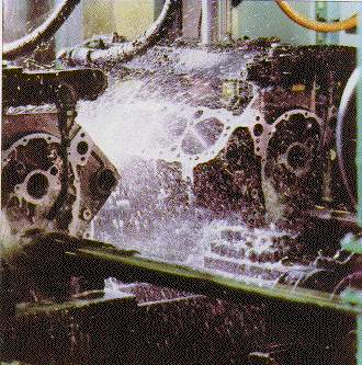
2.3 Application of Cutting Fluid
The principal methods of cutting fluid application include:
| Flood Application of Fluid
a flood of cutting fluid is applied on the workpiece |
 |
| Jet Application of Fluid
a jet of cutting fluid is applied on the workpiece directed at the cutting zone |
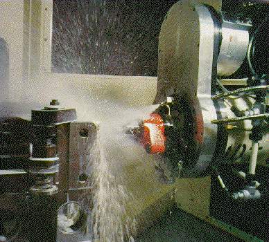 |
| Mist Application of Fluid:
cutting fluid is atomised by a jet of air and the mist is directed at the cutting zone |
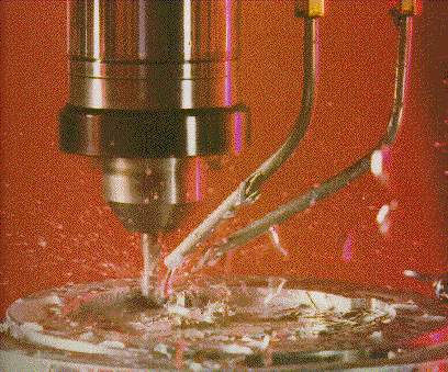 |
2.4 Selection of suitable cutting fluids
According to El Baradie (1996) and Cakir(2007), there are various factors involved when selecting cutting fluids in machining process. Three factors that are involved in the selection process of cutting fluids are as mentioned below:
- Type of machining processes.
- Type of machined workpiece material.
- Type of cutting tool material.
2.4.1 Type of machining processes.
When selecting cutting fluids, the characteristics of machining process should be taken into consideration. The combinations between cutting tool-chip and workpiece material is related with the variation of machining process. El Baradie (1996) mentions that cutting fluids will be used more on most difficult machining process. A very good literature study in cutting fluid application gave similar significant data; machining process were organized according to the volume of cutting fluid used in the machining operation from the least amount to the highest amount (Cakir, Yardimeden and Ozben, 2007):
- Grinding
- Cutting with saw
- Turning
- Planning and shaping
- Milling
- Drilling
- Reaming
- Threading (using high cutting speed and low feed rate)
- Threading operation with shape tools
- Boring
- Drilling deep holes
- Gear production
- Screwing with thread
- Screwing with tap
- Outer broaching
- Inner broaching
Cakir, Yardimeden and Ozben (2007) decided that this categorization from utilizing less cutting fluids to high would be a general approach and this would not provide explained view of the type machining processes, the machined workpiece material and the cutting tool material and cutting tool geometry variables could change this order.
Heavy or middle cutting oils usually used in the heavy machining operations such as screwing and broaching. This is because of the chemical component of the heavier active oil that make it suitable for the horizontal broaching of steel. Compared to the water based cutting fluids, oils based has displayed better performance in broaching operations and their chemical components help out in making the machining operation easier. (El Baradie, 1996).
For the drilling machining operation, because of the two-cutting edge of the drill tool the cutting speed applied is usually low and make the process a bit problematic. As noted by Belluco and De Chiffre (2001), the cooling effect of cutting fluid is important because of this and the geometry of the formed chip is different. In order reducing the friction on conventional drilling process, chlorine or sulphur additive mineral oils and emulsion oils should be selected for less heat generation. Another preferred method is by using advanced drill tools such as holed drill for cutting fluid application (El Baradie, 1996).
As a result of using new cutting tool materials such as hard metals and high cutting speeds in turning, milling and grinding machining processes, water based cutting fluids is fit for the application (El Baradie, 1996). When high cutting speed are used, the contact period between workpiece material and cutting tool is short. Therefore, penetration of cutting fluids will not be sufficient and crater wear on cutting tool can be seen more often. In order to minimize the effect of generated heat on cutting tool wear, water based cutting fluid are used (Ebbrell et al., 2000).
2.4.2 Type of machined workpiece material.
Type of workpiece material is another factor for selection of suitable cutting fluids. According to El Baradie (1996), cutting fluid application should provide easy machining operation in all material. Cutting fluid application with the different types of workpiece material will be mentioned in this section (Avuncan, 1998)
Workpiece from cast iron group is a brittle material and when undergoing machining operation will break into small size chips. Because of small size chip formation, the friction between chip and cutting tool is minimal. Avuncan (1998) proposed that in order to prevent the dust formation and increasing the surface finish quality during machining operation emulsion cutting fluid should be used. To decrease the oxidation during machining, the concentration of emulsion cutting fluid should be kept around 12%-15% (Zitoune, 2013).
For steel machining process, usually the high pressure carrying additive cutting fluids are applied. High pressure cutting oils is preferred when machining stainless steel. During machining process of steel, work-hardening properties in some steels can cause some problems and Avuncan (1998) proposed using sulphur added oils. However, by using this type of oils for steels machining operation produce stain over the machined surface.
Water based cutting fluids are preferred when machining heat resistant and difficult-to-cut steel alloys because temperature becomes higher in cutting area. For this type of machining operation, the mixture ration of water based cutting fluids changes between 1/20 – 1/40 and in some machining operations, using sulphur added mineral cutting oils is possible (Ebbrell et al., 2000).
When machining workpiece materials from aluminium and aluminium alloys, high temperatures did not occur as those materials are easy to machine. In this case, waterless cutting fluids can be applied and it can stop the built-up edge formation during machining operation but this type of cutting fluid must be non-active so that it can leave no stain to the surface. (Ebbrell et al., 2000)(Avuncan, 1998).
As noted by Avuncan (1998), when machining nickel and nickel alloys, the machining operation had better be conduct with dry or using cutting fluid. When cutting fluids are applied when machining these type of material, the parameter of cutting speed and feed rate should be higher. For turning with high cutting speed, drilling and milling operation, water based cutting fluid are applied. The usage of synthetic cutting fluids is feasible for broaching and drilling operations. Usually for this sort of material sulphured mineral oils as cutting fluid is chosen. (Avuncan, 1998) (Ebbrell et al., 2000).
High temperature becomes an important factor when selecting cutting fluid for machining difficult to machine material such as titanium alloys. Therefore, the effect of heat produced during machining process will be eliminated when applying cutting fluids. Cutting fluids used in machining titanium alloys must have cooling and lubricating characteristics. Due to high heat generation from machining titanium alloys operation, the cooling factor from the cutting fluid is more important. This will also enable to use higher cutting speed during machining operation. When low cutting speed are selected, the lubrication properties of cutting fluids are favoured. When high cutting speed are selected for machining titanium alloys, chlorine additive cutting oils are preferred; for low cutting speed, emulsion oils can be applied (Zitoune, 2013).
Trent and Wright (2000), has provided general guideline when selecting cutting fluids based upon various testing and experience as shown in Table 2.1.
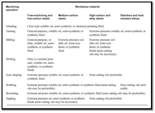
Table 2.1: Guide to cutting fluid selection for general workshop application (Trent and Wright, 2000).
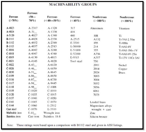
Trent and Wright (2007) has divided metals into six classes and used them in making cutting fluid selection chart of Table 2.2.
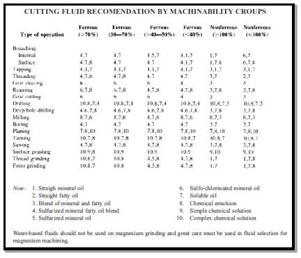
Table 2.2: Cutting fluids recommendation by machinability groups (Trent and Wright, 2000).
2.4.3 Type of cutting tool material.
Cutting tool material is another important factor when selecting cutting fluid in machining operation. Currently there are wide variety of cutting tool material commercially available for all kinds of machining operations.
Generally, all type of cutting fluids can be applied with cutting tool made from high speed steel. But, when machining difficult-to-cut material such as titanium alloys, waterless cutting fluid are favourable.
When using tungsten carbide(WC) cutting tools for machining operation, the cooling characteristics from cutting fluids are much more preferred. Reason for that is because of high heat produced from cutting tool and workpiece material when machining process occur. Excessive heat generation during machining with WC cutting tools can cause rapid tool wear therefore reducing tool life and the surface finish quality. (Avuncan, 1998) (Cakir, Yardimeden and Ozben, 2007).
According to Cakir, Yardimeden and Ozben (2007), cutting tools made from Cubic boron nitrate (CBN) and polycrystalline diamonds (PCD) are costly although they can maintain their characteristics in high temperature machining operations. Because of that, they are usually applied in finishing operation to get high dimensional accuracy and exceptional surface finish level. When machining processes are carried out with these cutting tool materials, the application of cutting fluids is not required.
Beside from CBN and PCD cutting tools, ceramic and diamond cutting tools similarly can keep their features at high temperatures. Usually they are used in the last machining process. Air is sprayed into the cutting zone when using ceramic cutting tools while for diamond type cutting tool, water based cutting fluids can be applied (Avuncan, 1998) (Cakir, Yardimeden and Ozben, 2007).
2.5 Factors Associated when Using Cutting Fluid
2.5.1 Health and Safety
The use of cutting fluids in material removal processes can pose significant health and safety risks. Any cutting fluid that generates a mist, whether it be water or oil based, may cause respiratory ailments such as chronic bronchitis, occupational asthma and loss of lung function (Sutherland and Kulur, 2000). Prolonged exposure may cause cancer of the oesophagus, stomach, pancreas, larynx, colon and rectum (Gunter and Sutherland,1999). It is for this reason that there are strict limits on the amount of mist a machine operator can be exposed to. In the UK these limits stood at 3mg/m3 for oil based cutting fluids and 1mg/m3 for water based cutting fluids (Health and Safety Executive, 2002) but at the time of writing it understood these limits are under review.
There is also a serious hazard of skin dermatitis when water based fluid systems are used (Howes and Tonshoff, 1991) and they are always susceptible to bacteriological activity that can be potentially damaging to health (Horner, 2003; Coughlin and Williams, 1992). Water based fluid systems therefore require the use of anti-bacterial agents that require frequent checks and possible replenishment, with the subsequent impact on full life cycle costs.
2.5.2 Economic Cost
Cutting fluids represent a significant proportion of the total manufacturing costs, with surveys showing that between 7%-17% (Klocke and Eisenblatter, 1997) of the total production costs are attributable to the use of cutting fluids when the cost of purchase, maintenance and waste disposal are taken into consideration. Some suggest that the cost is even higher, nearly 20% (Brinksmeier and Brockhoff, 1997) and whilst these figures may be reasonably old, both sets of results were published in 1997, it is clear there are significant costs associated with the use of cutting fluids.
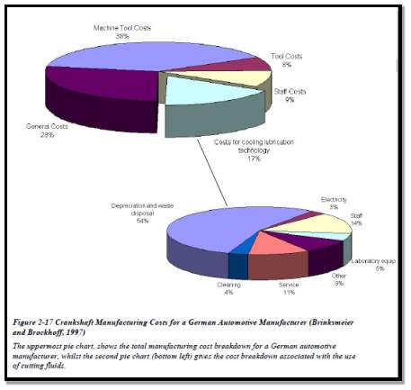
Figure 2‑1: Manufacturing cost pie chart (Brinksmeier and Brockhoff, 1997).
2.5.3 Environmental
In recent years the environmental impact of all lubricants, which obviously includes cutting fluids, has lead to a raft of legislation being introduced aimed at minimising any potential ecological damage. For instance European legislation has forced the removal of nitrite from cutting fluids as well as short chain chlorinated paraffin’s which were used for as extreme pressure additives (Bartz, 2001).
However, legislation is not the only factor forcing both the manufacturers and end users of cutting fluids to investigate what impact cutting fluids have on the environment. Bartz (1998) lists a total of five drivers which are:
1) Environmental Facts
2) Public Awareness
3) Government Directives and Regulations
4) Globalisation of Markets
5) Economic Incentives
Environmental facts and public awareness of these facts go hand in hand in putting pressure on companies to adopt more environmentally conscious policies. Government legislation on the other hand tends to force companies to reduce the toxicity of all waste including cutting fluids being returned to the environment and to increase the biodegradability of their waste products (Bartz 1998).
In recent years, a number of environmentally friendly biodegradable cutting fluids have been introduced into the market. A biodegradable cutting fluid is one where microorganisms can ingest and metabolise the fluid and essentially return it to nature.
2.6 Cutting Fluid Selection Methods
Section 2.2 has listed cooling and lubrications as two important effects of the cutting fluid. It’s ability to reduce the heat generation by means of lubrication, and to cool the worked zone are the most obvious attributes of the cutting fluid to the machining operations. Various methods have been developed in order to these cutting fluid performances. This section will provides an overview of the methods available and the meaning of the results.
2.6.1 Pin and V-Block Test
The pin and V-block test is perhaps the most widely recognized of the rubbing tests. Two steel jaws having a V-shaped notch in them apply pressure to a rotating steel pin immersed in fluid as shown in Figure 2‑2.
Two different tests can be run with this machine. ASTM method D3233 covers a technique of increasing pressure on the jaws until failure, in order to measure the load carrying properties of the fluid. ASTM method D2670 measures the antiwear properties of a fluid as a ratchet mechanism advances in order to maintain a constant load on the pin. The number of teeth advanced by the ratchet during the prescribed testing period is reported as the measure of pin wear.
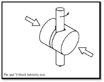
Figure 2‑2 Pin and V block test (Byers, 2006)
Table 2.3 provides data on five metalworking fluids developed using these two ASTM methods. The fluids are arranged with the high oil products at the top of the table, synthetics and water at the bottom. Note that a very light-duty, clear synthetic gave the lowest number of teeth wear and was comparable to the heavy-duty soluble oil on failure load. This result is due to the incorporation of a small amount of antiwear additive, which allows the light-duty product to pass the rubbing test, but will in no way assure heavy-duty cutting or grinding performance. Note, also, that in the case of the two soluble oils, chlorine, and sulphur additives improved the failure load, but did not eliminate the wear.
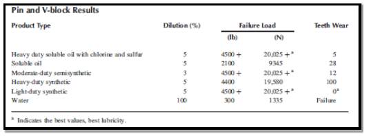
Table 2.3 Pin and V block results (Byers, 2006)
2.6.2 Block on Ring
A metal block under an applied load against a rotating steel ring has been used by R. Kelly and J. Byers to compare can drawing fluids and by A. Molmans and M. Compton to compare cutting and grinding fluids as shown in Figure 2‑3. Several measurements can be made from this test:
a. Frictional force
b. Wear scar measurements on the block
c. Weight loss measurements on the block
d. Failure load at which the lubricant film ruptures
ASTM methods D2714 and D2782 cover these procedures. The Reichert test is similar, using a cylindrical steel roller pressed against the rotating steel ring. The lower third of the ring is bathed in lubricant residing in a cup-shaped reservoir. As the ring rotates, it produces an elliptical wear mark on the roller. The size of the worn area is related to the load-carrying capacity of the lubricant.
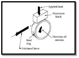
Figure 2‑3 Block on ring test (Byers, 2006).
2.6.3 Four-Ball Test
The four-ball tester uses three steel balls held stationary in a cup-shaped cradle while a fourth ball rotates against the others under an applied load (see Figure 7.5). Using this basic concept, two different types of tests may be run. One test measures the size of the point contact wear scars on the three stationary balls after a specified time under a constant speed of rotation and load (ASTM D4172). This test is used to determine the relative wear preventive properties of various fluids. The second test measures extreme pressure capability by using a constant speed of rotation with increasing loads until welding occurs (ASTM D2783). D. Kirkpatrick has used both techniques to compare synthetic, semisynthetic, and soluble oil metalworking fluids.
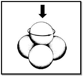
Figure 2‑4: Four ball test (Kirkpatrick,1980).
2.6.4 Soda Pendulum
The friction pendulum or Soda-pendulum can be used to measure the coefficient of friction over a wide range of temperature as shown in Figure 2‑5 . The pendulum spindle is supported by four balls in a cup containing the test fluid. If no friction was present, the pendulum arm would swing constantly from side to side with no change in the width of swing. Friction, however, makes each swing shorter than the previous one. The coefficient of friction can be calculated from the amplitude of any two subsequent swings.
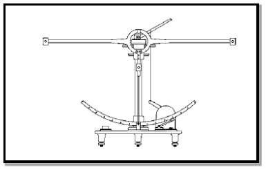
Figure 2‑5: Soda Pendulum (Byers, 2006) .
2.6.5 Lathe Tests
Dr. Charles Yang has described a lathe test using a single point, V-shaped tool that simulates chip crowding conditions found in heavy-duty machining operations. He has shown that the vertical cutting force provides a reliable method for predicting tool wear, which can be difficult to measure accurately. Using this lathe method, Dr. Yang demonstrated that the presence of 125 ppm calcium water hardness significantly reduced the cutting forces, indicating improved lubrication with a metalworking fluid mix, compared with the same fluid diluted with deionized water. Thus, water quality can have a significant effect on the lubricating properties of metalworking fluids. Low- to medium-water hardness can improve lubricity, but high-water hardness almost always leads to a loss of performance.
Dr. L. DeChiffre has also developed a lathe test, in which he measures frictional force, tool wear, and chip–tool contact length. Using Dr. Yang’s method and SAE 1026 steel, cutting force values were determined for the same five metalworking fluids shown in Table 2.3. Table 2.4 shows that water performed poorly on the lathe test, followed by the light-duty synthetic. A simple soluble oil and a moderate-duty, low-oil content semisynthetic gave almost identical results. These results show that oil alone does not provide the lubricity. A heavy-duty soluble oil with chlorinated and sulfurized additives performed better than the simple soluble oil. Finally, note that a heavy-duty clear synthetic gave the best results (lowest forces).
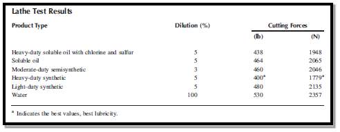
Table 2.4: Lathe test results (DeChiffre,1982).
2.6.6 Grinding Test
The grinding process also makes chips, but at temperatures and speeds that may be much higher than for a machining operation. A grinding wheel can be considered as a cluster of randomly oriented, negative rake cutting tools, which are chemically very different from the tools used in machining. It is, therefore, important to evaluate metalworking fluids for their ability to reduce grinding wheel wear or increase metal removal rates.
A simple, horizontal spindle surface grinder can be used to evaluate the grinding ratio or G-ratio.18,24 The G-ratio is obtained by dividing the volume of metal removed by the volume of wheel lost due to wear. High G-ratios indicate low wheel wear and good grinding performance. Surface finish and power consumption may also be measured.
Table 2.5 shows data from a moderate-duty surface grinding test on SAE 8617 steel using a vitrified bond, aluminum oxide wheel with the same five fluids from Table 2.3 and Table 2.4. Note that the heavy-duty soluble oil provided the best G-ratio, surpassing both the heavy-duty synthetic, which performed well on the lathe, and the light-duty synthetic that was best on the pin and V-block test. Each condition has a different set of fluid requirements for optimum performance.
Many other types of grinding operations may also be used for metalworking fluid evaluations.
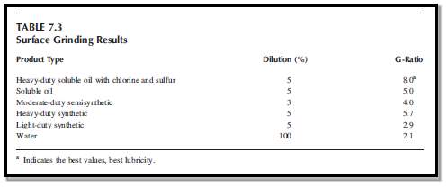
Table 2.5: Surface grinding results.
2.6.7 Drilling Test
Several investigators have used drilling tests to evaluate metalworking fluids. Dr. Herman Leep (1981) compared drilling, turning, and milling test methods, and found that testing with high-speed steel drills was “the best method for discriminating between different cutting fluids.” The number of holes drilled, surface roughness, tool wear, torque, and cutting forces have all been used as discriminators by various investigators.
2.6.8 Tapping Torque Test
Much has been written in recent years about the tapping torque tester. The interest in this test is due to the fact that it is perhaps the only bench-scale metal cutting test available. Torque values are measured as a tap cuts threads into a predrilled hole in a metal specimen, which can be made of various metals. The average torque value of five runs is then calculated. Test results may be expressed either as a simple torque force value or as a percent efficiency, the ratio of the average torque value of a reference fluid to that of the test fluid. The same tap is used on both the reference fluid and the test fluid. L. DeChiffre states that an evaluation of surface finish is also necessary.
Table 2.6 lists tapping torque efficiency values for four of the metalworking fluids used in previous comparisons. Two different cutting speeds were used with 1215 steel. At 400 rpm the data shows very little correlation with in-plant experience or with lathe test results. Note that the heavyduty soluble oil and heavy-duty synthetic looked worse than the moderate-duty semisynthetic. At 1200 rpm, the light-duty synthetic, moderate-duty semisynthetic, and the heavy-duty soluble oil behave more or less as expected; but the heavy-duty synthetic was a complete failure. This may indicate that the lack of rubbing lubricity seen with this product on the pin and V-block test is an important factor in the tapping test. These data underscore the need for careful selection of the test conditions in order to generate reliable conclusions.
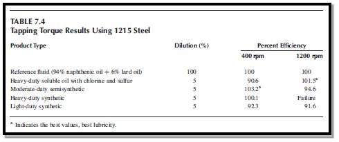
Table 2.6: Tapping torque results (Byers, 2006).
2.7 Summary
From literature review, in order to define optimised cutting fluid selection method, it was important to know first cutting fluid types, its roles and application in the machining process. From literature review, the main principle criteria when selecting cutting fluid are:
- Process performance.
- Cost performance.
- Environmental performance.
- Health and hazard performance.
In order to evaluate cutting fluid process performance, various methods have been developed as shown in Section 2.6. Main criteria of cutting fluid that have been selected for this project are its process performance (heat transfer and lubrication) and cost.
3 Evaluation Test Program
This chapter will show theoretical analysis for heat transfer performance for different types of cutting fluids in turning operation by using software developed from Microsoft Visual Studio.
3.1 Heat Transfer Model in Turning Operations
By using cutting fluids in turning operation, the heat transfer between the workpiece and fluid is given by (M. Daniel, Olson and Sutherland, 1996):
| q=hA(Tw-Tf) | (1) |
Where
qis heat transfer rate,
his heat transfer coefficient,
Ais surface area,
Twis wall temperature of workpiece, and
Tfis fluid temperature.
Heat transfer coefficient in turning process comes from:
| h=Nu.kD | (2) |
where
Dis diameter of the workpiece,
kis thermal conductivity of the workpiece, and
Nuis Nusselt number. According to M. Daniel, Olson and Sutherland (1996), Nusselt number depends on machining operation which in this case for turning flood application is:
| Nu=0.1075Pr0.35[0.5Rer2+Ret2]0.35 | (3) |
Where
Pris Prandtl number and
Reis Reynolds number which are given by:
| Re=ρVDμ | (4) | |
| Pr=μcpk | (5) |
Where
ρis mass density,
Vis generic velocity,
μis dynamic viscosity,
cpis specific heat and
kis thermal conductivity of workpiece material.
There are two Reynolds number for turning process with cutting fluid flood application as shown in Eq (3). The rotational Reynolds number (
Rer) rest on the peripheral velocity of the workpiece while transverse Reynolds number (
Ret) varies with cutting fluid velocity as shown in Figure 3‑1 .
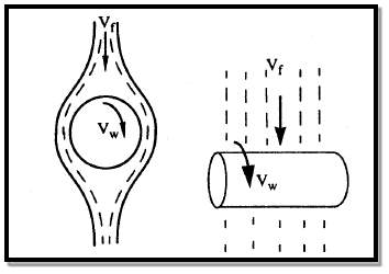
Figure 3‑1 Velocity vectors in flood application (M. Daniel, Olson and Sutherland, 1996).
Therefore, velocity in
Rercomes from spindle speed and the formula to convert rpm to linear velocity is:
| revmin×1min60sec×2πD21rev | (6) |
As shown in Eq (4) and (5), cutting fluids properties such as dynamic viscosity
μ, specific heat capacity
cp, and mass density
ρare needed for calculating the specific heat transfer coefficient. While cutting fluid manufacturer and vendors providing information about chemical composition and recommended oil concentration, other information about cutting fluid properties are not available.
For this heat transfer model, will used historical data gathered from M. Daniel experiment as shown in Table 3.1.
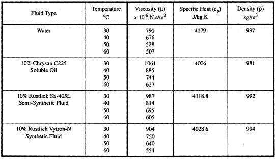
Table 3.1: Cutting Fluid Properties (M. Daniel, Olson and Sutherland, 1996).
3.2 Cost Model for Cutting Fluids
Cost estimation model for cutting fluids has been developed based on previous studies (Gonzalez, 2007). The cost model needs a functional unit, a reference unit to which the inputs and outputs can be related. In this case, 1000 hours of work is selected.
This functional unit, 1000 hours of work, refers to the working hours of the factory, which does not mean that the machine is running all that time. In other words, if the factory is running 8 hours per day, it is equivalent to 125 working days.
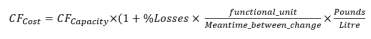
| CFCost=CFCapacity×(1+%Losses × functional_unitMeantime_between_change×PoundsLitre | (7) |
Equation (7) calculates cutting fluid cost during the number of working hours (functional unit), 1000 hours. ‘Capacity’ stands for the cutting fluid system’s capacity in litres. It is assumed that the cutting fluid system will be totally emptied from time to time (meantime_between_changes) and replaced with new fluid. The parameter ‘losses’ describes fluid losses that exist, which can vary from 10% to 30%. These losses are due to fluid coating on the chip and on the workpiece, and evaporation.
3.3 Creating Database for Cutting Fluids
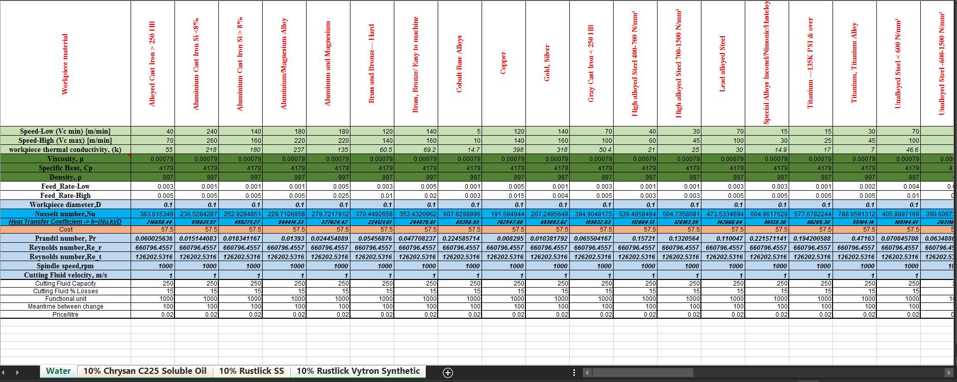
The data for the cutting fluids are taken from Table 3.1, and the data for the workpiece material are from matweb.com. Four different types of cutting fluids and 19 types of workpiece materials are arranged using Microsoft Excel as shown in Figure 3‑3 . Each sheet tab is for different types of cutting fluids and the first row shows different types of workpiece material.
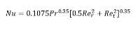


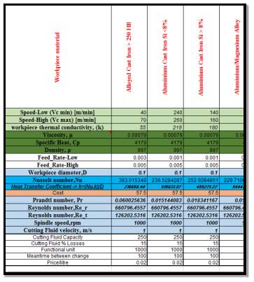
Figure 3‑2:Integrating formula into database.


3.4 Integrating Database into Program
 Open Excel file containing your data base
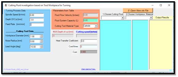
- Choose the data base file as required as shown in figure below.

Figure 3‑5: Selecting database

 Changing cutting fluid and workpiece material will analyse result of calculations done in excel database.
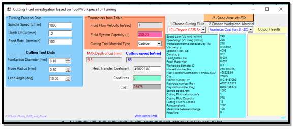
Figure 3‑6: Selecting cutting fluid and workpiece material.
- Changing the fluid flow velocity and spindle speed will set the program to recalculate the output value in excel database.
4 Results and Discussions
Other than experimentally determined cutting fluid properties from Table 3.1, to run the software, the following hypothetical data also need to be provided to the program:
| Cutting Fluid Data | |||||
| Water | 3% Chrysan Soluble Oil | 10% Chrysan Soluble Oil | 10% Rustlick Semi-Synthetic | 10% Rustlick Synthetic | |
| Cutting fluid flow velocity | 1m/s | 1m/s | 1m/s | 1m/s | 1m/s |
| Fluid System Capacity | 500 L | 500 L | 500 L | 500 L | 500 L |
| Cost/Litre | 0.002 £/L | 9£/L | 11 £/L | 10 £/L | 8 £/L |
| Turning Process Data | |||||
| Workpiece Material | Alloyed Cast Iron | ||||
| Spindle Speed | 1000 rpm | ||||
| Diameter of the workpiece | 0.1m | ||||
Using above input data, the heat transfer coefficient for a turning operation with flood application are shown in Table 4.2.
| Fluid Type | Heat Transfer Coefficient W/m2K |
| Water | 72112.15 |
| 3% Chrysan C225 Soluble Oil | 67605.61 |
| 10% Chrysan C225 Soluble Oil | 65583.27 |
| 10% Rustlick Semi-Synthetic | 66009.13 |
| 10% Rustlick Vytron Synthetic | 71310.32 |
Table 4.2: Heat transfer coefficients between four fluids.
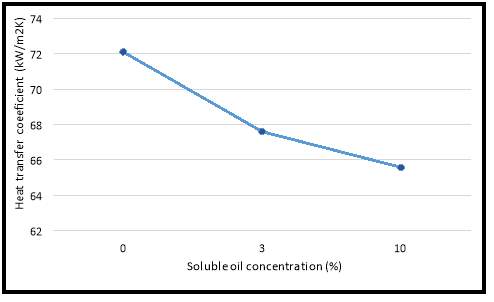
Figure 4‑1: Oil concentration effect on heat transfer coefficient
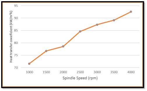
Figure 4‑2: Spindle speed effect on heat transfer coefficient.
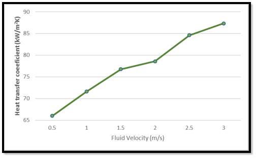
Figure 4‑3: Fluid velocity effect on heat transfer coefficient.
The above results indicate that synthetic cutting fluids performs better in heat transfer compared with semi-synthetic and soluble oils. Although water has high heat transfer coefficient but it is a poor lubricant. From Figure 4‑1, as the oil concentration increases in soluble oil fluids, the heat transfer performance reduced. Another important factor that influence the heat transfer rate between workpiece and cutting fluid are cutting fluid parameters. As shown in Figure 4‑2 and Figure 4‑3, spindle speed and cutting fluid velocity influence heat transfer coefficient in turning machining operation. For 1000 hours of cutting time with the cutting fluid exchanged every 100 hours and estimated loss of 15%, the cutting fluid costs are shown in Table 4.3. These quantitative results help the software users to evaluate different types of cutting fluid and select one that is suitable for the operations.
| Fluid Type | Cost (£) |
| Water | 57.5 |
| 3% Chrysan C225 Soluble Oil | 25875 |
| 10% Chrysan C225 Soluble Oil | 31000 |
| 10% Rustlick Semi-Synthetic | 28750 |
| 10% Rustlick Vytron Synthetic | 23000 |
Table 4.3: Cutting fluid costs.
5 Validation of Cutting Fluid Test Program Data
In order to validate the results from previous chapter, pendular scratch test has been proposed. Because of limited resources, the test was not performed and this section will only present an overview and procedure involves for the mentioned process based upon historical data.
5.1 Pendular Scratch Test
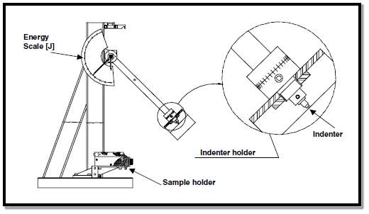
Figure 5‑1 : General view of pendular instrument (Liang.1996).
Pendular scratch test is selected as a way to validate the data (heat transfer efficiency) because of the relationship between specific energy and heat exchange capacity. This test was designed and built by Franco (1989) and Figure 5‑1 shows a general view of the instrument.
The aim of this test is to produce a scratch in a sample with an indenter to calculate the specific energy involved in the process. The sample surface is submerged in a layer of cutting fluid as shown in Figure 5‑2. This is achieved by using a tape to create a suitable wall to contain the fluid. The sample is weighed before and after the scratch.
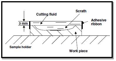
Figure 5‑2: Work piece sample submerged in cutting fluid (Franco,1989).
The indenter is fixed at the extremity of the pendulum, with previously adjusted mass. It is let go from a defined height (initial potential energy) to scratch the sample located at the rest position of the pendulum in oil. After the scratch, the pendulum rises to a certain height, which is recorded on a scale. The scale registers directly the energy consumed in the test, i.e. the difference between the initial and final potential energy of the pendulum. The specific energy is calculated, which is the ratio between the energy used to scratch the sample and the loss in mass.
Sales, Machado, Bonney and Ezugwu (2007) had conducted the test with four different types of fluids and a dry run. The fluids that were examined are water, neat(straight) oil, emulsion(soluble) oil, and synthetic oil. The result is shown in Figure 5‑3.
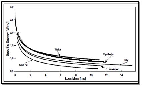
Figure 5‑3: Specific energy consumed during scratching with mass loss (Sales et al., 2007).
Sales (2007) stated that the fluids with higher heat exchanged capacity generate higher specific energy. Those with higher lubricity ability have a lower specific energy. Figure 5‑3 shows that synthetic oil has excellent cooling (heat transfer) and low lubricating properties. This correlates with the data from previous chapter (heat transfer efficiency).
6 Conclusion and Recommendation
The aim of this work is to defined optimised cutting fluid selection method but owing to the complexity of field conditions, no single test machine can simulate the performance requirements for all in-plant metalworking operations. That is why it is so difficult, or even impossible, to correlate bench test data with actual performance. Therefore, several different lubricity tests should be used to evaluate cutting fluids.
This work was also intended to provide a broad overview of the many selection and evaluation methods applied to cutting fluids. In the interest of space and the reader’s time, no attempt was made to give complete, step-by-step instructions. Instead, many references have been listed for those desiring further details. None of these procedures should be considered to be the final word on testing methods.
Because of limited time and resources, the author can only choose lathe or turning test to evaluate different types of cutting fluids. The cutting fluid criteria that are compared and discussed are heat transfer performance and cost. Further cutting fluids criteria can be added and will be discuses in section 6.1.
The software uses experimentally measured fluid thermos-physical properties stored in cutting fluid database along with analytical model to predict the performance in terms of heat transfer coefficient and costs. The data base used for quantitative computation of cutting fluid performance is modular and easily expandable. The cutting fluid data can be added from different sources, including experimentally measured data, and other vendor provided information. The results in terms of cutting fluid heat transfer coefficient and cost still need to be validated in order to be compared with its actual performances. The output gives quantitative information regarding cutting fluids process performance and help user to select suitable fluids for turning operation with flood application. The results obtained still need further validation to evaluate the effectiveness of the test program.
6.1 Future Work
Recommendations for the future works are as bellows:
- Adding control volume for turning heat transfer model to know the wall temperature to get the heat transfer rate between the cutting fluid and workpiece.
- Currently only one module present in the software; turning with flood application. Other machining operations can be added such as turning with jet application, cylinder boring for evaluating temperature distribution in boring with and without cutting fluid and tapping process for tapping torques and axial forces.
- Aside from thermos-physical properties of cutting fluid, other types of data can be included such as chemical compositions, pollutant loading and health hazards. The database can be expended more by gathering information from National Institute for Occupational Safety and Health (NIOSH), Occupational Safety and Health Administration (OSHA), etc.
- After gathering required information, cutting fluid criteria that can be evaluated can be expended to environmental impact, health and safety hazard, and the cost for the treatment as well in the plant.
- American Society for Testing and Materials (ASTM), 1916 Race Street, Philadelphia, PA 19103, USA.
- Avuncan, G. (1998). Machining Economy and Cutting tools,. 1st ed. Istanbul: Makine Takm Endüstrisi Ltd. Publication, pp.375-403.
- Belluco, W. and De Chiffre, L. (2001). Testing of vegetable-based cutting fluids by hole making operations. Lubrication Engineering, 57, pp.12-16.
- Cakir, O., Yardimeden, A. and Ozben, T. (2007). Selection of cutting fluids in machining processes. Achievements in Materials and Manufacturing Engineering, 25(2).
- DeChiffre, L., Function of cutting fluids in machining, Lubr. Eng., 44(6), 514–518, 1988.
- DeChiffre, L., Laboratory Testing of Cutting Fluid Performance, Lubrication in Metal Working, Vol. 2, Third International Colloquim at Esslingen, Germany, pp. 74.1–74.5, 1982.
- Deluhery, J. and Rajagopalan, N., A turbidimetric method for the rapid evaluation of MWF emulsion stability, Colloid Surf. A, 256, 145, 2005.
- Ding, Y. and Hong, S. (1995), A Study of the Cutting Temperature in Machining Process Cooled by Liquid Nitrogen. Technical Paper of NAMRC XXIII.
- Ebbrell, S., Woolley, N., Tridimas, Y., Allanson, D. and Rowe, W. (2000). The effects of cutting fluid application methods on the grinding process. International Journal of Machine Tools and Manufacture, 40(2), pp.209-223.
- El Baradie, M. (1996). Cutting fluids: Part I. Characterisation. Journal of Materials Processing Technology, 56(1-4), pp.786-797.
- Gonzalez, A. (2007). Machine Tool Utilisation Phase: Costs and Environmental Impacts with a Life Cycle View. Ph.D. Royal Institute of Technology.
- Kelly, R. and Byers, J., Synthetic fluids for high speed can drawing and ironing bodymakers, Lubr. Eng., 40(1), 47–52, 1984.
- Kirkpatrick, D., Trend to Synthetic Cutting Fluids, Conference on Lubrication, Friction and Wear in Engineering, Institution of Engineers, Australia, 1980.
- Leep, H. R., Investigation of synthetic cutting fluids in drilling, turning and milling processes, Lubr. Eng., 37(12), 715–721, 1981.
- Liang, Y.N., Li, S.Z., Li, D.F. and Li, S, 1996, ‘Some developments for single-pass pendulum scratching”, Wear, Vol. 199, No. 1, pp. 66-73.
- M. Daniel, C., Olson, W. and Sutherland, J. (1996). Effect of Cutting Fluid Properties and Application Variables on Heat Transfer in Turning and Boring Operations. Japan/USA Symposioum on Flexible Automation, 2, pp.1119-1126.
- Merchant, M. (2001). Mechanics of the Metal Cutting Process. I. Orthogonal Cutting and a Type 2 Chip.
- Molmans, A., and Compton, M., Heavy duty synthetic metalworking fluids are a reality, Synthetic Lubricants and Operational Fluids, Fourth International Colloquium at Esslingen, Germany, pp. 401–405, 1984.
- Niezabitowski, W. and Nachtman, E., Way and Gear Oil, Hydraulic Fluids and Greases as Contaminants in Water Base Metal Removal Fluids: Corrosion and Foam Effects, Strategies for Automation of Machining: Materials and Processes, ASM International, New York, pp. 167–170, 1987.
- Rieger, M., Stability testing of macroemulsions, Cosmet. Toiletries, 106(5), 59–69, 1991.
- Roehl, E. L., Sakkers, P. J. D., and Brand, H. M., Isostearic acid and isostearic acid derivatives, Cosmet. Toiletries, 105(5), 79–87, 1990.
- Russell, W. R., Cutting tools for cutting fluid evaluation, Lubr. Eng., 30(5), 252–254, 1974.
- Sales, W., Machado, Á., Bonney, J. and Ezugwu, E. (2007). Evaluation of cutting fluids using scratch tests and turning process. Journal of the Brazilian Society of Mechanical Sciences and Engineering, 29(4).
- Salmon, S. (2006). Metal Cutting Processes. In: J. Byers, ed., Metalworking Fluids, 2nd ed. Boca Raton: CRC Press, pp.48-56.
- Smith, M. D. and Lieser, J. E., Laboratory evaluation and control of metalworking fluids, Lubr. Eng., 29, 315–319, 1973.
- Soković, M. and Mijanović, K. (2001). Ecological aspects of the cutting fluids and its influence on quantifiable parameters of the cutting processes. Journal of Materials Processing Technology, 109(1-2), pp.181-189.
- Springborn, R. K., Cutting and Grinding Fluids: Selection and Application, American Society of Tool and Manufacturing Engineers, pp. 10–11, 1967.
- Taylor, F. (1907). The Art of Cutting Metals. Scientific American, 63(1618supp), pp.31-58.
- Thornhill, F., Other parameters and measurement advantages, In Monitoring and Maintenance of Aqueous Metalworking Fluids, Chater, K. W. A and Hill, E. C., Eds., Wiley, Chichester, 1984.
- Trent, E. and Wright, P. (2000). Metal Cutting. 1st ed. Butterworth-Heinemann, pp.311–337.
- Woskie, S. et al., Factors affecting worker exposures to metalworking fluids during automotive component manufacturing, Appl. Occup. Environ. Hyg., 9(9), 612–621, 1994.
- Xavior, M. and Adithan, M. (2010). Evaluating the performance of cutting fluids in machining of AISI 304 austenitic stainless steel. International Journal of Machining and Machinability of Materials, 7(3/4), p.262.
- Xu, R., How to disperse particulates, R&D Mag., 45(7), 20, 2003.
- Yang, C., The effects of water hardness on the lubricity of a semi-synthetic cutting fluid, Lubr. Eng., 35(3), 133–136, 1979.
- Zitoune, R. (2013). Machining of titanium alloys and composites for aerospace applications. 1st ed. Durnten-Zurich [u.a.]: Trans Tech Publ.
Appendix 1 – Machinability Groups
 Appendix 6.1
Appendix 2 – Installation guide
A prototype version of the software was created on CD-ROM, however improvements may have been made during and after the database software. This improvement over the prototype software may due to the limitations of the database and is subject to change by the owner.
Cite This Work
To export a reference to this article please select a referencing stye below:
Related Services
View all


Related Content
All TagsContent relating to: "Engineering"
Engineering is the application of scientific principles and mathematics to designing and building of structures, such as bridges or buildings, roads, machines etc. and includes a range of specialised fields.
Related Articles

DMCA / Removal Request
If you are the original writer of this dissertation and no longer wish to have your work published on the UKDiss.com website then please: