Data Link Layer and Physical Layer in Computer Networking
Info: 8294 words (33 pages) Dissertation
Published: 3rd Dec 2021
Abstract
Over the decades the computer systems have evolved a lot, the two major technological revolutions were the development of powerful microprocessors which had more computing power but for a smaller price leading to the price-performance revolution, making the hardware available for a reasonable cost to the user and development of the efficient interconnection structures (Local networks) which allows hundreds of machines to connect together and transfer information between machines in microseconds. These advances in computer hardware, networks have increased the demand for Distributed Computer Architectures. Communication is the most important aspect of the distributed computer architecture, as multiple computers are connected over a common network to transfer the data.
In this paper, I have considered the standard Open System Interconnection Reference Model of computer networking, to explain about communication and protocols in the distributed computer systems especially with the Data link layer and Physical layer of the OSI model, explaining about the process, protocols and services provided by these layers.
Keywords: Distributed Computer Architecture, OSI Model, Data Link Layer, Physical Layer
Introduction
Over the decades the computer systems have evolved a lot, LeLann G. (1981) discusses that the two major technological revolutions were the development of powerful microprocessors which had more computing power but for a smaller price leading to the price-performance revolution, making the hardware available for a reasonable cost to the user and development of the efficient interconnection structures(Local networks) which allowed hundreds of machines to connect together and transfer information between machines in microseconds. The driving force for these revolutions were the increasing needs of users which seems to become more sophisticated every day. Motivated by these developments in technologies and sophisticated needs of users the distributed computer systems came into picture.
According to Tanenbaum, A. S., & Steen, M. V. (2006), Distributed system is defined as connectivity of the various independent systems together and appears to the user as single system performing the task. Each computer in the distributed system has its own memory and operating system, and they collaborate with each other to transfer the messages over the communication network ideally making it look like a single system performing the tasks to the users or programs.
Why Distributed System Architecture?
Tanenbaum, A. S., & Steen, M. V. (2006 p.3) defined some of the important characteristics of a distributed computer architecture as below that makes it more reliable and advantageous over centralized architectures is
- Making resources accessible, makes it easy to share the remote resources and exchange the information in a controlled and efficient way between the machines.
- Distribution transparency, the ability to show or make the user believe that it is single system while in the background the tasks and resources are distributed across the various computers connected over the communication network [Tanenbaum, A. S., & Steen, M. V. (2006 p.3)].
- Openness, the system can interact with other open systems available and not restricting itself to a defined environment. Also, it is easy to replace existing components or add components to the system without affecting the process carried out by the system.
- Scalability, the system scalability is obtained by taking into consideration either of the perspectives
- With respect to size i.e., addition of more users and resources to the system anytime.
- With respect to geographical distance, the users and resources may be far apart.
- With respect to administrative scalability, it can be easily managed even if it is distributed between multiple organizations.
Internetwork communication is an important aspect of the distributed computer architecture, the exchange of information between the multiple systems happens through the underlying network connecting them. Since the distributed systems doesn’t have a shared memory, all the communication happens through sending and receiving low-level messages unlike the primitives in the shared memory in a non-distributed system [Tanenbaum, A. S., & Steen, M. V. (2006 p.3)]. With the tremendous diversity between processes communicating, we need to follow some standard protocols to communicate efficiently and reliably. For example, consider a communication between machine A and machine B, If they were no rules set for the communication and process A sends a word encoded in ISO 8859-1-character code and B is expecting a different word in English encoded in ASCII, then the communication would not be optimal and not a great use of distributed architecture. A protocol could be a set of rules that describes the objects and operations to be agreed upon between two or more processes to exchange the information. Many agreements may be needed at different levels of communication on how to represent the information. To make it easier and to resolve these issues involved with communication, the International Standards Organization(ISO) came up with a reference model with layered architecture identifying the levels with specifics tasks to carry out. This reference model is called as Open Systems Interconnection Reference Model(OSI).
Open Systems Interconnection Reference Model (OSI)
The reference model tells how the systems in the distributed architecture can communicate with each other by adhering to the standards and protocols providing a standard way of communication. As per the article [OSI model. (2018, January 22)], It describes how the information is communicated from application program of one system through the network to the application on other system in the distributed architecture without having to understand the internal structure of the layer, by dividing the steps involved in communication into layers or level. The standard OSI model is divided into seven layers. Each layer has a well-defined function to perform on part of communication and dividing the information into smaller manageable chunks which are processed independent of others and provides service to the preceding layer. The below diagram, Figure 1[Computer Science notes, Networks and Distributed Systems. (n.d.).] shows the seven layers of the OSI model.

Figure 1: Seven Layers of OSI Model [Computer Science notes, Networks and Distributed Systems. (n.d.).]
The below table gives brief description of data units and functions of the seven layers of OSI model given by Stallings, W. (2014).
| Protocol Data Unit | Layer | Function | |
| Upper
Layers |
Data | 7. Application Layer | The user interacts with the system at this layer and the layer is responsible to identifies the communicating partner, determine if any resources are available and synchronizes the communication and provides distributed information services. |
| 6. Presentation Layer | This layer eliminates the problem of data representation so that the network can understand, by converting the data from the application layer to network format, send the data across the network by formatting and encrypting data free from compatibility issues. Also, transform data to a form application layer can understand on the receiving end. | ||
| 5. Session Layer | This layer is responsible to establish, manage or terminate the connection sessions between the hosts during the communication. | ||
| Segments | 4. Transport Layer | This layer is responsible to take the data from the preceding top layer and divide it into segments to transfer across the network link. | |
| Lower
Layers |
Packet / Datagram | 3. Network Layer | This layer provides the mean to transfer the data from sending host to receiving host through the network link. The data is transformed in the form of data packets. |
| Frame | 2. Data Link Layer | This layer is responsible to provide transport reliable data through the network link by breaking the data into frames and reassemble the received frames. | |
| Bit | Physical Layer | This layer defines the electrical and physical specifications for the devices, rules for how the data in bits is transmitted from one system to another. |
In this paper, we will describe in detail about the last two abstract levels of the Open Systems Interconnection Reference Model for networking of the distributed system architecture, data link layer and physical layer.
Physical Layer
The lowest layer of OSI reference model is physical layer. It is the layer that is connected to the actual network link that connects two or more nodes physically on the distributed network, making it actual carrier of information between the nodes. This layer defines the electrical and physical specifications for the devices, rules for how the data in bits is transmitted from one system to another through the physical network [OSI Physical Layer. (n.d.).]. It serves the data link layer, the peer layer above it and provides the means to transmit the data link layer frame into bits, it accepts the frame and encodes them into a series of signals transmitted over the network link and on the received end restore them to back to and send it the to the data link layer as a complete frame.
The three basic functions of the Physical layer [OSI Physical Layer. (n.d.).] as shown in Figure 2[OSI Physical Layer. (n.d.).] below are:
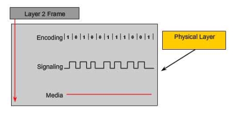
Figure 2: Physical Layer Fundamental principles [OSI Physical Layer. (n.d.).]
Physical components
The components like electronic hardware devices, media, physical links are responsible for transmitting and carrying signals representing the bits [OSI Physical Layer. (n.d.).].
Data Encoding
Data Encoding, converts stream of bits into predefined codes which is group of bits that are used to make predictable pattern which can be recognized by both the sender and receiver. These patterns will help to differentiate the data bits from the control bits and provide better media error detection and identify the beginning and end of frame and transmit to the receiver through the network
Signaling
To represent the bits of 1 and 0 as digital signals, the physical layer generates electrical, optical or wireless signals. The layer defines some standards to represent the bits in signals by using some signaling methods based on the complexity of the data.
Data Link Layer
Data Link Layer, the second layer of the OSI reference model for computer networking has an objective of transferring reliable, error-free data from one node to another node over the physical layer. As the OSI reference model allows each layer to function without being much concerned about the responsibilities of other layers, Baig, Z. (1970, January 01) refers that the Data Link layer provides not only the functional but also procedural means to transfer the data over the physical layer or network link with necessary synchronization, error control and flow control by dividing the data into frames and transmitting them sequentially making the data reliable for the receiving node and also relieving the top layers from the responsibility of adding data on the network link and also receiving data.
Data Encapsulation in Data Link Layer
Each layer in OSI Model uses Protocol Data Units (PDUs) to communicate to its peer layers on other hosts [DataLink Layer. (n.d.).]. These hold the control information attached to the data, which has the information about which nodes are communicating to each other, when will the communication start and end between the node, what errors have occurred during the communication and which nodes will be communicating next. The Control Information can be of header or trailer form. Headers are added in the beginning to data passed down from upper layer and Trailers are added to the end of data that has been passed down from upper layers. Based in this at a given OSI layer, the data portion of an information unit can contain headers, trailers, and data from all the upper layers and this is called encapsulation [Data Encapsulation. (2014, February 25).]. Each PDU is attached to the data by encapsulating it on each layer and given a specific name in the header which is read only by peer layer on the receiving end and ones read it is stripped off from the header and moved to the next layer. The figure 3 [Data Encapsulation. (2014, February 25).] below shows how the data is encapsulated and passed on to the peer layers.
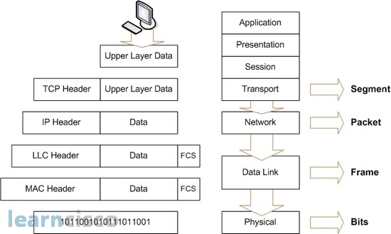
Figure 3: Data Encapsulation of Message
Data Link Layer encapsulates every network layer datagram or packet by creating a data link frame before transmitting to physical layer or network link.A frame in data link layer includes
- Data: The datagram inserted from the Network layer.
- Header: control information with physical addresses and is appended to the beginning of the PDU.
- Trailer: control information appended to the end of the PDU
The below figure 4 [DataLink Layer. (n.d.).] shows the encapsulation of the datagram from network layer into the data link frame.
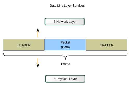
Figure 4: Data Encapsulation in Data Link Layer
The data link frame is formatted in such a way that it is understandable by the physical layer and received by the nodes and can be properly decoded in to packets at the destination network layer.
Data Link Sub-layers
The Data link layer is typically divided into two sublayers as shown in the below figure 5 [ComputerNetworking. (n.d.).] to provide wide variety of services to the network. By dividing the it into sublayers, it will allow one type of frame defined by the upper layer to access different types of media defined by the lower layer [Internetworking. (n.d.).].
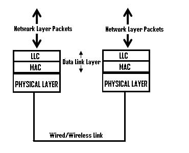
Figure 5: Sub-layers of Data Link Layer
They are defined as below
Logical Link Control Layer (LLC)
The upper layer of the data link layer (Logical Link Control) provides service to the network layer, places the information about the network layer protocol on the frame and interacts with lower layer (MAC). The LLC is responsible for multiplexing and de-multiplexing of the network layer protocols. On sending end, the LLC layer obtain the information of the network layer protocol such as IP, IPX, ARP etc., fill it in the header portion of the frame (multiplexing) and pass that to MAC layer below [ComputerNetworking. (n.d.).]. On receiving end, LLC layer is responsible to take the frame from the physical layer, identify the network protocol and pass on the datagram to the right network layer protocol on the network layer above (de-multiplexing). Also, the LLC provides optional services such as flow control, acknowledgment and error detection.
Media Access Control Layer (MAC)
This lower sublayer interacts with the physical layer and it defines who will have access to the media access processes that were performed over hardware. Also, it provides the framing of the data into frames that is transmitted over the physical layer, these frames contain information about the physical signaling requirements of the medium and also the type of data link layer protocol in use for the transmission.
Operations of Data Link Layer
Below are the operations that are supported by the Data Link Layer:
Framing
The data in the data link layer from the network layer is divided into smaller chunks of data called Frames which encapsulates the network layer data in such a way it is understandable by the Physical layer for reliable and error free data to be the destination. The frames are accepted by the physical layer and sends out in the form of stream of bits without any regards to the structure or format of the data and so it one of the operation of the data link layer where it creates some well-defined boundaries for the data when they are divided to frames. This is accomplished by adding some special bits patterns for the frame at the beginning and ending of it.
For example, in the below figure 6 [DataLink Layer. (n.d.).] we can see how the data is formatted for transmission in the Data link frame. The frame has three parts a header, data, a trailer.
Header
The frame header contains the control information specified by the Data Link layer protocol to provide the features that were demanded by the communication environment.
Typical frame header fields include:
- Frame Start and Stop: Indicate the beginning and end limits of the frame.
- Addressing: Consists of the physical addresses of the source and destination hosts.
- Type: Indicate the type of PDU that is contained in the frame.
- Quality Control – controls flow of the data.
The quality control field can be base different based on the link layer protocol and media used for the transmission.
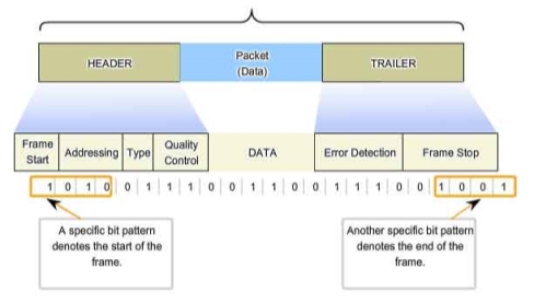
Figure 6: Framing of Data [DataLink Layer. (n.d.).]
Trailer
A trailer is added to the end of the data in the frame, it includes a field for error detection and the last field for to indicate the ending of the frame. This helps in determining if any errors were detected in the received frame which is discussed in the later section. This helps to provide reliable data to the upper layers.
Physical Addressing
The header of the data link layer frame has a field for addressing which is used for transporting the data across the network link. This field consists of the physical addresses, which is the source address of the frame and the destination address of the frame transmitting over the network link. These addresses are specific to the local network and can be used only for the transmission with in the same network [Data Link Layer | Layer 2. (n.d.).]. This is a useful operation provided by the data link layer which helps to deliver the data to the right destination in a largely interconnected system and to verify the source of data for the receiver.
Error Detection and Correction
Error detection and correction are important operations supported by the Data Link layer. Kurose, J. F., & Ross, K. W. (2017), mentioned that when the data is transmitted across the network link, there is high chance of the signals on the network link being interfered by distortion, attenuation and electromagnetic noise. These disturbances can end up substantially change the bit values represented by the signals causing bit errors, the receiving node can misinterpret that the bit in a frame is one when it transmitted as zero, and vice versa. As it could be not worth to send up an error prone datagram to the network layers, the data link layer provides a mechanism to detect these bit errors. A frame consists of a trailer added to the end of the data which consists of field generally referred as frame sequence check(FSC) which determines if any errors that occurred while the transmission and reception of the frame. The frame on the transmitting node has the error-detection bits in the FSC field of the trailer and when the frame is transmitted to the receiving node the error check is performed. Error correction works the same as way error detection except that it will detect and correct the bit errors by determining where exactly in the frame the error has occurred. [ Kurose, J. F., & Ross, K. W. (2017)].
Mostly seen errors are single bit error, meaning only one bit of the data changed from 1 to 0 and 0 to 1 causing the error and burst error, meaning two or more bits of the data are changed causing the error. The error-detection and correction techniques allow the receiver to detect the bit errors occurred, but it is not always 100% reliable and can still be a possibility that an undetected bit error is received in the data and receiver will be unaware of it. Thus, to reduce the probability of such occurrences few must choose the error-detection scheme accordingly.
Error Detection Techniques
Parity Checking:
A simple form of error detecting technique. Parity will add a single bit that indicates whether the number of 1 bits in the preceding data is even or odd [Kurose, J. F., & Ross, K. W. (2017)]. The parity checking can be visualized indifferent schemes. In this method, the error is detected if a single bit is changed in the data. When a single bit has changed it will change the parity bit and error is detected. Parity checking could not be very robust technique, when the number of bits is more than one such as in burst errors. Also, the parity doesn’t indicate in the particular bit in which the error has occurred when it detects it.
Checksum:
In the checksumming techniques, the bits of the data are considered as the sequence of n-bit integers. In this method these n-bit integers are added, and the resulting sum is used as the error-detection bits. When the data is sent, the data is divided into n bits and then added using 1’s complement and is complemented again and sends the data to the receiver. On the receiver end, the data is again divided into segments and added again with 1’s complement. If the result is zero and data is considered as accepted.
Cyclic Redundancy Check (CRC)
The CRC is one of the widely used and efficient technique for error detection on the received frame. It’s based on the technique of binary division of the data and the remainder of it being appended to the data in bits and sent to the receiver. The receiver also divides the received data by the same divisor, if the remainder is zero then it is considered as no error in the data and passed to the next layer else it is considered as an error detected in the data. On the sending side, the data unit that is being sent is divided by a pre-determined divisor, to obtain the remainder which is called as cyclic redundancy check bits (CRC). The CRC has one bit less than the divisor (if CRC has n bits then divisor has n+1 bits). The flow of the CRC technique is shown as below in figure 7 [Computer Networks | Error Detection. (2017, May 29)]
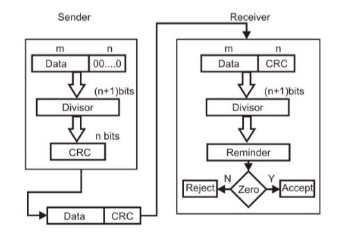
Figure 7: Flow Diagram for Cyclic Redundancy Check(CRC) [Computer Networks | Error Detection. (2017, May 29)]
The data unit from the sender is appended with n bits which is divided by a predefined divisor which is n+1 bit and then the remainder obtained (CRC) of n bits is added to the data and sent to the receiver. The data received on the receiver end is divided with the exact same predefined divisor. If remainder is zero, then it is considered as no error and if not zero then the data is rejected at that point.
The CRC calculations are derived by a complex algorithm of modulo-2 arithmetic without carries in addition or borrows in subtraction equivalent to the bitwise exclusive-or (XOR) of the operands. CRC can also be referred as polynomial codes since it is possible to see the bit to be sent as polynomial with coefficients of 0 and 1 values in the bit and operations performed on the bit are polynomial arithmetic.
Flow Control
The nodes on each side of the transmission over the network link have a limited amount of frame capacity [T. (n.d.). DCN Data-link Control and Protocols.]. This could become a potential problem, for example if the receiving node is processing the received frames slowly compared to the rate the frames are sent to it then it could serious congestion over the network and it could be overwhelming on the receiving node sometimes causing frames to be lost. We could expect that the sender and receiver would on the same speed to resolve this issue but in real work it’s not feasible. To resolve this important issue, the data link layer provides flow control as a service or operation to its peers. Flow control ensures that the transmitting devices does not overwhelm the receiving one with and data and also improves efficiency. [Communication Networks/Error Control, Flow Control, MAC. (n.d.).]. Two types of approaches are provided for control of the flow by data link layer which are based on the feedback i.e. the sender doesn’t the next data until it hears back from the receiver about previous data. They are as below
- Stop-and-Wait
- Sliding Window
- One-Bit Sliding Window
- Go Back N
- Selective Repeat
Stop-and-Wait:
In this mechanism, the sender sends the data and will have to and stop and wait for an acknowledgement from the receiver for the data received and the sender cannot send next data until the receipt of acknowledgement as shown below in the figure 8[T. (n.d.). DCN Data-link Control and Protocols.].
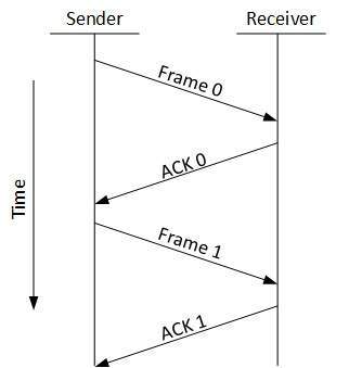
Figure 8: Stop and Wait ACK [T. (n.d.). DCN Data-link Control and Protocols.].
It is simplest way for flow control, but not an efficient approach it is assumed the data is error free but in reality there would be errors for sure, so if the senders send the data but on the receiver end the data is having errors and cannot verify and send the acknowledgment which would block the whole data as the sender will not able to send anything without acknowledgment.
Sliding Window:
To resolve the issues faced by the stop and wait mechanism where sender is dependent on receiver. In this approach, the sender and receiver both will use buffer of same size, which would avoid the necessity to wait for the sender and can send data one by one without waiting for receiver acknowledgement. It also provides efficient use of bandwidth as the sender and receiver will use the network to send data and receiver would send an acknowledgement with data which it wants to send so that the sender doesn’t have to wait unnecessarily to send the second data, it can send one after one without wait until the receiver acknowledges. It also provides efficient use of bandwidth as the sender and receiver will use the network to send data and receiver would send and acknowledgement with data which it wants to send to sender. This process is called as piggybacking.
One-Bit Sliding Window:
In this approach, the buffer size is of one bit which makes it that the sender and receiver can only send 0 and 1. It provides the sequence, acknowledgement and packet number and uses a full-duplex channel. It works fine when the sender is first sending the data and then receiver start sending data after it receive the data but if both sender and receiver send data simultaneously then it leads to errors or duplication of packets.
Go Back N:
In this approach, the sender is provided with a window size and it sends the frames without receiving any acknowledgement of previous one. The receiver is also provided with a large window size or window size to receive multiple frames and acknowledge and keeps track of the sequence of the frames. After the sender sends all the frame and it checks the sequence of the received ACK. If a NACK is received at a particular frame then all the frames are transmitted back after that particular NACK, though ACK were received for the frames in the sequence after that particular frame, shown in the below figure 9[T. (n.d.). DCN Data-link Control and Protocols.].
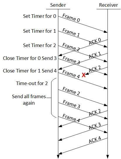
Figure 9: Go Back N Protocol [T. (n.d.). DCN Data-link Control and Protocols.]
Selective Repeat:
In this approach, unlike the previous approach where all the frames after a NACK for a frame must retransmitted, a buffer space is provided for the window size of the receiver, which will buffer the frames in the memory and in a situation of NACK for a particular frame, only that frame is retransmitted. Below figure 10 shows the Selective repeat ACK flow [T. (n.d.). DCN DCN Data-link Control and Protocols].
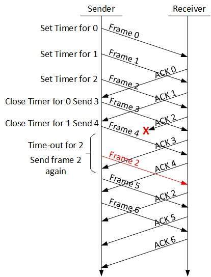
Figure 10: Selective Repeat [T. (n.d.). DCN Data-link Control and Protocols.]
Media Access Control
The data link layer provides access control through the Media Access Control layer (MAC) which is a lower sublayer. MAC communiactes with the physical layer and controls the access over the data frames on the shared network. It uses unique addressing identification, such as MAC addresses, and channel access control based on different protocols for the access control.
MAC Address:
A MAC address is the unique address and is a sub-set of the data link addresses. MAC addresses are forty-eight bits in length and are expressed as 12 hexadecimal digits [Internetworking. (n.d.).]. IEEE 802 administers first six hexadecimal digits, which helps to identify the manufacturer or vendor and thus comprise the Organizational Unique Identifier (OUI). The below figure 11 shows the representation of MAC address [MAC address. (2018, January 23)].
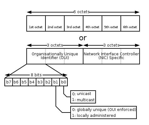
Figure 11: MAC Address [MAC address. (2018, January 23)].
These are used in most the network technologies to identify the machine on the network. The MAC address is incorporated in to the computer hardware device for network which is the Network Interface Card(NIC).
Network Interface Card
Network interface cards (NICs) or network adapter is a computer hardware device that is inside a computer user to connect to other computers over network. In other words, it is a device that is used to join multiple computer over the local access network. Without this device in the computer it cannot communicate to the outside world through the network. The network interface card operates in the data link layer of the OSI reference model for networking which is inserted into the system bus of the computer and connect the software processes and physical media [NIC – Network Interface Card. (2011, November 13)]. It is a single, special-purpose chip performing the data-link layers. Also, the network interface care is associated with the unique 48-bits MAC addresses that can be obtained from the lower layer of the data link layer. Each NIC is associated with an MAC address which is burned on it by the manufacturer and no two NIC have the same addresses thus ensuring the computer to the network are unique and helps identify the computer in an inter connected system. A NIC considered for a computer based on three principles, they are bandwidth i.e., how much data can flow through the network in a period, type of media the NIC is used for and the network architecture it will used in. A picture of the network interface card is shown below in figure 12 [Network interface cards (NIC). (n.d.)].
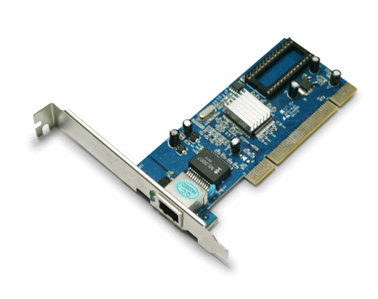
Figure 12: Network Interface Card(NIC)
MAC Protocols:
The choice of MAC protocol impacts the reliability and efficiency of network transmissions. Some of concerns to be considered are the ability of the machines to access the network within a reasonable period which determines acceptable access and response times. Also, there is high chance of collisions to access the data in the shared medium as multiple machines will be trying to access the data, so there is a need for some protocol for collision detection or to avoid them. Considering all the thoughts and concerns and to provide a better access control, Media Access Control Protocols can be categorized into Contention-Free and Content-Based protocol as in the below figure 13 [Dargie, W., & Poellabauer, C. (2011)].
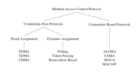
Figure 13: MAC Protocols
Few are explained below:
Contention-Free Medium
In this protocol the collisions for access are avoided by providing exclusively allocated resources for each node. Some of the example are below.
Fixed Assignment
FDMA: Frequency Division Multiple Access, in this the frequency band is divided into several small bands of frequency, in this case the data transfer between a pair of nodes use one frequency band and rest of the nodes use a different frequency band.
TDMA: Time Division Multiple Access, in this protocol the multiple devices depend on the periodic time windows to use the same frequency band, these time frames have a fixed number of slots for transmission and it helps to separate the devices to use the media at different time periods to avoid collisions. The slot defines which node can use the media at what time.
CDMA(Code Division Multiple Access), accesses the wireless medium simultaneously with the help of using different codes if these codes are orthogonal, it is possible for the multiple communications to share the same frequency band forward error correction (FEC) at the receiver is used to recover from interferences among these simultaneous communications.
Dynamic Assignment
To make efficient use of the resources, in these protocols the nodes are given access to media on-demand bases. For example, in polling protocol it uses a controlling device to issue small polling frames in a round-robin fashion such that each node is asked if there is data available for transmission if not it goes to next node.
Contention-Based Medium
In this protocol target to avoid or detect the collisions when multiple devices are trying to access the medium simultaneously.
- ALOHA: ALOHA uses acknowledgments to confirm successful data transmission which allows nodes to access the medium immediately and avoid collisions by exponential back-off approach [Dargie, W., & Poellabauer, C. (2011)].
- Carrier Sense Multiple Access (CSMA): It is a network method in shared network where the nodes attached to the network can listen before transmitting to avoid collisions [Dargie, W., & Poellabauer, C. (2011)]. They are two methods to obtain it as below
- Collision Detection (CSMA/CD) sender will first sense the medium to determine if it is idle/busy – if it is found busy, the sender stops from transmitting packets and if the medium is idle, the sender can initiate data transmission [Dargie, W., & Poellabauer, C. (2011)].
- Collision Avoidance (CSMA/CA) CSMA/CD requires that the sender should be aware of any collisions, that’s how CSMA/CA attempts to avoid collisions in the first place.
- MACA and MACAW: Multiple Access with Collision Avoidance (MACA) is a dynamic reservation mechanism sender which will indicate a desire to send with a ready to send (RTS) packet and the intended receiver will respond with clear to send (CTS) packet [Dargie, W., & Poellabauer, C. (2011)].
Types of Data Link Protocols
The data link protocols can be categorized into two based on the type of transmission [Hura, G. S., & Singhal, M. (2001).].
Asynchronous Data Link Protocol
In asynchronous protocol, each character in the bit stream are considered independently. A start and stop bit is sent at the beginning and ending of the character. This protocol is often referred as start and stop protocol as the transmitting node can transmit the character whenever it is possible, and the receiver node can accept the character [Hura, G. S., & Singhal, M. (2001).]. These protocols are slower than synchronous protocols generally used in modems.
Synchronous Data Link Protocols
In this protocol the whole bit stream is taken and divided into equal size of characters. It does need any start and stop bit, instead there is a defined bit pattern for preamble and postamble for the entire data. These bits are called as synchronizing bits [Hura, G. S., & Singhal, M. (2001)]. It is used for high speed networks as it has much lower head and provides faster transmission. These protocols are characterized into two groups.
Character- Oriented Protocol
In this the frame is considered as series of characters and control information is placed in a separate control frame or in the existing data frame. Example: Binary Synchronous Communication(BSC).
Bit-Oriented Protocol
In this frame is interpreted as series of bits and control information can be placed as bits in the information contained in the frame. This protocol can add more information into shorted frames. Example: SDLC and HDLC.
Synchronous Data Link Control Protocol(SDLC):
It was developed by IBM. In the below figure 14 [Hura, G. S., & Singhal, M. (2001).], the structure of the frame is shown.
| Flag
8 bits |
Address
8 bits |
Control
8 bits |
Message
(variable length |
FCS
32 bits |
Flag
8 bits |
Figure 14: Structure of Frame in SDLC
The flag is the start and end of frame, address field: address of receiver, control field: carries sequence number, ACK, requests/responses, FCS used for error checking and is of 16-bit.
High Level Data Link Control Protocol (HDLC):
This protocol is based on SDLC and provides best-effort unreliable service and a reliable service. It was developed by ISO by modifying SDLC. It is used with various serial interface protocols available with physical layer, such as EIA/TIA-232 etc.
Serial Line Interface Protocol (SLIP):
It is usually used to transmit IP packets between the sender and receiver. But this has some limitations as it doesn’t have error-detection or correction mechanisms available. So, it is dependent on higher-level protocols to perform the error checks.
Point-to-Point Protocol (PPP):
Point to point protocol is a robust protocol which would transport all types of packets between two nodes through a direct connection, without any host or other networking device [Hura, G. S., & Singhal, M. (2001).]. The frames contain field that would identify the type of protocol carried. It consists of three components; encapsulation component to transmit datagram through physical layer, to establish, configure, and test the link a link control protocol is used, to negotiate optional configuration parameters for the network layer network control protocols are used.
Frame Relay:
Frame Relay is a standardized wide-area networking (WAN) protocol that operates in both data link layer and physical layer. It uses a packet switching methodology [Hura, G. S., & Singhal, M. (2001).].
IEEE 802 Standard Development
With the increasing demand in the interconnected networks and recognizing the need to set some standards in the LAN (local area network) world, the Institute of Electrical and Electronics Engineering (IEEE) started a Project 802 [IEEE 802. (2018, January 23).]. It is named after the first meeting of the project, year and month which was 1980 February. The services and standards defined by IEEE 802 are mapped to the lower two layers, data link layer and physical layer of the OSI reference model. Considering some of the issues of collision due to multiple end nodes connected to same link and access control on the media in the data link layer, IEEE 802 logically divided the data link layer into two sub-layers as logical link control (LLC) and medium access control (MAC) and came with some standards needed to be followed. All the 802 standards provide a common upper layer to logical link layer(LLC) and the MAC protocol can be different based on the physical media used such as thick coax cable, twisted pair cable etc. In IEEE 802, all the protocols use the same address format of 48 bits which are globally unique addresses which helps to connect any interface into any LAN worldwide. They are up to 25 working groups of standards under IEEE 802 till date.
Wi-Fi (Wireless Fidelity)
Wireless Fidelity mostly called with the name Wi-Fi, refers to the standards that belong to the IEEE 802.11 workgroup for Wireless Local Area Network (WLAN). WLAN extends the use the local area network without any wires connected which was originally designed for the cable replacement in the corporate environments but soon it became popular for providing IP connectivity for houses, small offices etc. The word “Wi-Fi” corresponds to the name of the certification given by the company name Wi-Fi Alliance, for certifying the hardware devices used for implementing WLAN by confirming with the IEEE 802.11 standards for wireless networking.
IEEE 802.11 belongs to the IEEE 802 standards group maintained by the IEEE 802 LAN/MAN Standards Committee (LMSC) [ Wireless LAN 802.11 Wi-Fi. (n.d.)]. The IEEE 802.11 standards includes the physical layer and medium access control layer (MAC) of the data link layer specifications for implementing the Wireless local area network (WLAN) to support hoc and infrastructure. The physical layer provides the radio wave signaling and modulation features for the data to be transmitted and the data link layer acts as an interface between machine bus and physical layer close to Ethernet standards. Several developments have been made with the specifications for the project IEEE 802.11[Varma, V. K. (n.d.).]. With these several standards of Wi-Fi being available with different speeds and power requirements, high-speed local area network can be provided to connect multiple computers over the network which are not too far from the access point or located in range distance without any wires.
References
Baig, Z. (1970, January 01). Networking concepts. Retrieved January 25, 2018, from http://basicnetworkingconcepts.blogspot.com/2011/02/osi-layers.html
Communication Networks/Error Control, Flow Control, MAC. (n.d.). Retrieved January 30, 2018, from https://en.wikibooks.org/wiki/Communication_Networks/Error_Control,_Flow_Control,_MAC
Computer Networks | Error Detection. (2017, May 29). Retrieved January 28, 2018, from https://www.geeksforgeeks.org/error-detection-computer-networks/
Computer Science notes, Networks and Distributed Systems. (n.d.). Retrieved January 25, 2018, from http://www.pling.org.uk/cs/nds.htm
ComputerNetworking. (n.d.). Retrieved January 26, 2018, from http://computernetworkingsimplified.in/data-link-layer/components-data-link-layer-llc-mac/
Dargie, W., & Poellabauer, C. (2011). Fundamentals of wireless sensor networks: theory and practice. Hoboken, NJ: Wiley.
Data Encapsulation. (2014, February 25). Retrieved January, 2018, from http://www.learncisco.net/courses/ccna/part-1-internetworking/data-encapsulation.html
Data Link Layer | Layer 2. (n.d.). Retrieved January 25, 2018, from https://osi-model.com/data-link-layer/
DataLink Layer. (n.d.). Retrieved January 25, 2018, from http://www.highteck.net/EN/DataLink/Data_Link_Layer.html
Hura, G. S., & Singhal, M. (2001). Data and computer communications: networking and internetworking. Boca Raton: CRC Press.
IEEE 802. (2018, January 23). Retrieved January 28, 2018, from https://en.wikipedia.org/wiki/IEEE_802
Internetworking. (n.d.). Retrieved January 30, 2018, from https://www.cisco.com/cpress/cc/td/cpress/fund/ith/ith01gb.htm#xtocid1668412
Introduction to Wi-Fi (802.11 or WiFi). (n.d.). Retrieved January 30, 2018, from http://ccm.net/contents/802-introduction-to-wi-fi-802-11-or-wifi
Kurose, J. F., & Ross, K. W. (2017). Computer networking: a top-down approach. Boston: Pearson.
Learn Networking. (n.d.). Retrieved January 28, 2018, from http://learn-networking.com/network-hardware/what-is-a-network-interface-card
LeLann G. (1981) Chapter 1. Motivations, objectives and characterization of distributed systems. In: Davies D.W. et al. (eds) Distributed Systems — Architecture and Implementation. Lecture Notes in Computer Science, vol 105. Springer, Berlin, Heidelberg
MAC address. (2018, January 23). Retrieved January 30, 2018, from https://en.wikipedia.org/wiki/MAC_address
NIC – Network Interface Card. (2011, November 13). Retrieved January 29, 2018, from https://howdoesinternetwork.com/2011/nic
Network interface cards (NIC). (n.d.). Retrieved January 30, 2018, from http://networkingi.blogspot.com/2012/02/network-interface-cards-nic.html
OSI model. (2018, January 22). Retrieved January 25, 2018, from https://en.wikipedia.org/wiki/OSI_model
OSI Physical Layer. (n.d.). Retrieved January 25, 2018, from http://www.highteck.net/EN/Physical/OSI_Physical_Layer.html
Stallings, W. (2014). Data and computer communications.
T. (n.d.). DCN Data-link Control and Protocols. Retrieved January 29, 2018, from https://www.tutorialspoint.com/data_communication_computer_network/data_link_control_and_protocols.htm
Tanenbaum, A. S., & Steen, M. V. (2006). Distributed systems: principles and paradigms.
Varma, V. K. (n.d.). IEEE Emerging Technology portal, 2006 – 2012. Retrieved January 29, 2018, from https://www.ieee.org/about/technologies/emerging/wifi.pdf
Watson R.W. (1981) Chapter 2. Distributed system architecture model. In: Davies D.W. et al. (eds) Distributed Systems — Architecture and Implementation. Lecture Notes in Computer Science, vol 105. Springer, Berlin, Heidelberg
Wireless LAN 802.11 Wi-Fi. (n.d.). Retrieved January 29, 2018, from http://ethw.org/Wireless_LAN_802.11_Wi-Fi
Cite This Work
To export a reference to this article please select a referencing stye below:
Related Services
View all


Related Content
All TagsContent relating to: "Information Technology"
Information Technology refers to the use or study of computers to receive, store, and send data. Information Technology is a term that is usually used in a business context, with members of the IT team providing effective solutions that contribute to the success of the business.
Related Articles

DMCA / Removal Request
If you are the original writer of this dissertation and no longer wish to have your work published on the UKDiss.com website then please: