4D Printing Using Shape Memory Polymers
Info: 28390 words (114 pages) Dissertation
Published: 11th Dec 2019
Tagged: Technology
ABSTRACT
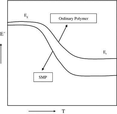
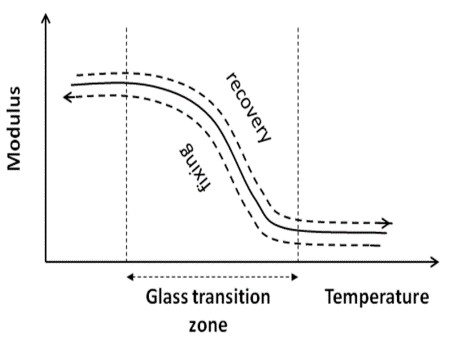 Figure 1 Figure 2
Figure 1 shows the difference in variation of the dynamic modulus of a SMP compared to an ordinary polymer[148][141].
Figure 2 shows how the Young's modulus of a SMP changes with temperature[149].
The basis of the shape memory effect in polymeric materials is the large difference between the Young's modulus of the SMP above and below the switching temperature compared to ordinary polymer as shown in figures(1 and 2). The low modulus favors the deformation in glassy state and high modulus favors the fixing of temporary shape at low temperature [12]. For a shape memory polymer to exhibit shape memory effect, the switch temperature (Tsw) of the reversible domain is vital. This switch temperature can be glass transition temperature (Tg) for the amorphous phase or melting temperature (Tm) for the crystalline phase[11].
When the temperature goes above Tsw, the molecular chains in the reversible domain of the SMP become mobile and can be easily deformed under external load. For example a curled shape can be made straight by stretching it above (Tsw). Then this deformation can be fixed or frozen by cooling it to a temperature below (Tsw) while the test specimen is still under external tension. When the external force is removed, the specimen will retain its temporary shape with no loss in strain. Finally when the temperature is again increased above the Tsw, the molecular chains release the deformation and recover back to their permanent shape due to their high mobility. This mainly happens because the molecular chains in polymers energetically prefer to return to their most disordered conformation[11].
3.1.1 Training and Characterization ofSMPs
Figure 1 Figure 2
Figure 1 shows the difference in variation of the dynamic modulus of a SMP compared to an ordinary polymer[148][141].
Figure 2 shows how the Young's modulus of a SMP changes with temperature[149].
The basis of the shape memory effect in polymeric materials is the large difference between the Young's modulus of the SMP above and below the switching temperature compared to ordinary polymer as shown in figures(1 and 2). The low modulus favors the deformation in glassy state and high modulus favors the fixing of temporary shape at low temperature [12]. For a shape memory polymer to exhibit shape memory effect, the switch temperature (Tsw) of the reversible domain is vital. This switch temperature can be glass transition temperature (Tg) for the amorphous phase or melting temperature (Tm) for the crystalline phase[11].
When the temperature goes above Tsw, the molecular chains in the reversible domain of the SMP become mobile and can be easily deformed under external load. For example a curled shape can be made straight by stretching it above (Tsw). Then this deformation can be fixed or frozen by cooling it to a temperature below (Tsw) while the test specimen is still under external tension. When the external force is removed, the specimen will retain its temporary shape with no loss in strain. Finally when the temperature is again increased above the Tsw, the molecular chains release the deformation and recover back to their permanent shape due to their high mobility. This mainly happens because the molecular chains in polymers energetically prefer to return to their most disordered conformation[11].
3.1.1 Training and Characterization ofSMPs
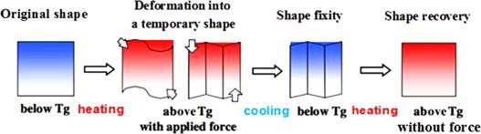 Figure 3. shows the programming – recovery shape memory cycle[145].
Programming- The sample is heated above its glass transition temperature and at this elevated temperature the sample is then deformed from point 1 to point 2.
Cooling- The sample is then cooled below its Tg at constant load. At low temperatures the load is removed and shape fixity is observed.
Reheating/recovery - Shape recovery is observed when the sample is reheated above its glass transition temperature. A sharp change in strain is observed when the sample is first heated above Tg due to recovery stress and the sample finally stabilizes at strain near the starting strain point. The recovery can be performed with constraints(constrained recovery) and without constraints (free recovery)[73,74].
Figure 3. shows the programming – recovery shape memory cycle[145].
Programming- The sample is heated above its glass transition temperature and at this elevated temperature the sample is then deformed from point 1 to point 2.
Cooling- The sample is then cooled below its Tg at constant load. At low temperatures the load is removed and shape fixity is observed.
Reheating/recovery - Shape recovery is observed when the sample is reheated above its glass transition temperature. A sharp change in strain is observed when the sample is first heated above Tg due to recovery stress and the sample finally stabilizes at strain near the starting strain point. The recovery can be performed with constraints(constrained recovery) and without constraints (free recovery)[73,74].
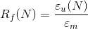 (1)
Here εm is the applied strain and εu(N) is the strain following the removal of the applied stress in Nth cycle.
(1)
Here εm is the applied strain and εu(N) is the strain following the removal of the applied stress in Nth cycle.
 Permanent shape recovery is observed when the sample is heated above Tg and the material recovers some portion of its permanent shape. The degree to which the sample recovers its permanent shape is characterized by the shape recovery ratio, Rr, given by [73-76]:
(2)
Here εm and εir are applied and irreversible strains respectively [159].
Permanent shape recovery is observed when the sample is heated above Tg and the material recovers some portion of its permanent shape. The degree to which the sample recovers its permanent shape is characterized by the shape recovery ratio, Rr, given by [73-76]:
(2)
Here εm and εir are applied and irreversible strains respectively [159].
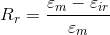
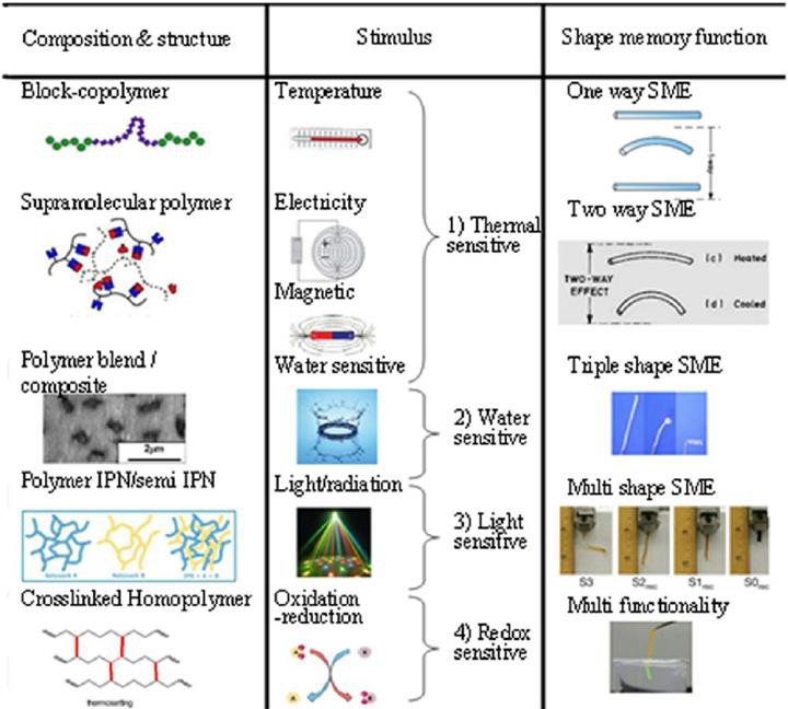 Figure 4. Shows classification of SMPs on the basis of composition, structure, stimuli and SME[143].
The progress in development of SMEs of SMPs have been remarkable. SMPs have developed to show two-way, triple and multiple SMEs. Apart from this biodegradability, multi-functionality( for example: permeable optic, thermo-chronic properties) can also be achieved in SMPs[139].
Figure 4. Shows classification of SMPs on the basis of composition, structure, stimuli and SME[143].
The progress in development of SMEs of SMPs have been remarkable. SMPs have developed to show two-way, triple and multiple SMEs. Apart from this biodegradability, multi-functionality( for example: permeable optic, thermo-chronic properties) can also be achieved in SMPs[139].
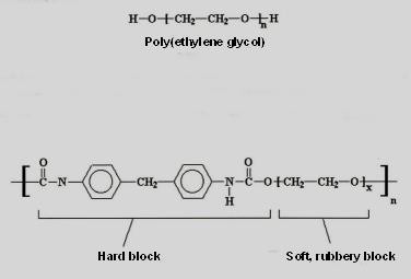 Figure 8. Molecular structure of a typical Polyurethane SMP depicting hard and soft segments in it[144].
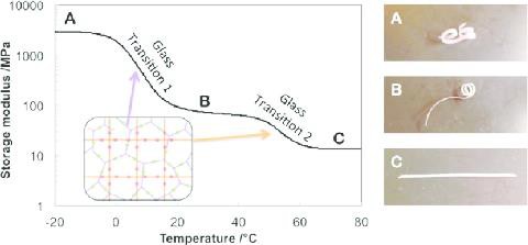 Figure 10. Storage modulus vs Temperature of a Triple SMP[147].
The physical methods include physical cross-linking of various crystalline polymers and bilayer structure of two double SMPs which have significant difference in their switching temperatures[44-46]. The most common technique used in past decades to make triple SMPS was mixing existing polymers with each other but only few polymer couples are completely or partially miscible. The two widely practiced techniques for mixing immiscible double SMPs are sea-island architecture and cocontinuous architecture. In polymer blends with sea-island architecture, one polymer (island) is dispersed in the continuous matrix of the second polymer (sea). Due to more number of particles of the continuous polymer (sea), its material properties are dominant in the blend. On the other hand cocontinous architecture has a significant advantage, in this each component forms a three-dimensionally per- locating network i.e. both components can be taken as continuous matrix and hence specifically good properties of both SMPs can be synergically combined[53-56]. Cocontinuous architecture has led to development of some novel materials enhanced electrical, mechanical, optical and transporting properties[47-50]. For example polyethylene/polypropylene blends are chemically cross-linked to give triple SMPs[51].
Figure 10. Storage modulus vs Temperature of a Triple SMP[147].
The physical methods include physical cross-linking of various crystalline polymers and bilayer structure of two double SMPs which have significant difference in their switching temperatures[44-46]. The most common technique used in past decades to make triple SMPS was mixing existing polymers with each other but only few polymer couples are completely or partially miscible. The two widely practiced techniques for mixing immiscible double SMPs are sea-island architecture and cocontinuous architecture. In polymer blends with sea-island architecture, one polymer (island) is dispersed in the continuous matrix of the second polymer (sea). Due to more number of particles of the continuous polymer (sea), its material properties are dominant in the blend. On the other hand cocontinous architecture has a significant advantage, in this each component forms a three-dimensionally per- locating network i.e. both components can be taken as continuous matrix and hence specifically good properties of both SMPs can be synergically combined[53-56]. Cocontinuous architecture has led to development of some novel materials enhanced electrical, mechanical, optical and transporting properties[47-50]. For example polyethylene/polypropylene blends are chemically cross-linked to give triple SMPs[51].
 (3)
Here Htotal is the total Helmholtz energy at a certain temperature T; Hr is the Helmholtz energy of the material in rubbery phase at T>Tg ; Hg is the Helmholtz energy of the material in glassy phase at T<Tg; fr and fg are volume fractions of rubbery and glassy phase and are functions of temperature.
In the 2nd process, the deformation storage or SMP's resistance to inelastic deformation below glass transition temperature arises due to the intermolecular resistance to segmental rotation and the entropic resistance to the molecular alignment. It is believed that the glassy phase formed during cooling may have different deformation history and hence is further divided into two phases: initial glassy phase (IGP) and frozen glassy phase (FGP). IGP refers to the glassy phase in initial configuration of the material and is deformed initially (at the beginning of an analysis) under application of external load. FGP on the other hand refers to the newly formed glassy phase caused by decrease in temperature [66].
Therefore, the Helmhotz energy equation can be revised and written as:
(3)
Here Htotal is the total Helmholtz energy at a certain temperature T; Hr is the Helmholtz energy of the material in rubbery phase at T>Tg ; Hg is the Helmholtz energy of the material in glassy phase at T<Tg; fr and fg are volume fractions of rubbery and glassy phase and are functions of temperature.
In the 2nd process, the deformation storage or SMP's resistance to inelastic deformation below glass transition temperature arises due to the intermolecular resistance to segmental rotation and the entropic resistance to the molecular alignment. It is believed that the glassy phase formed during cooling may have different deformation history and hence is further divided into two phases: initial glassy phase (IGP) and frozen glassy phase (FGP). IGP refers to the glassy phase in initial configuration of the material and is deformed initially (at the beginning of an analysis) under application of external load. FGP on the other hand refers to the newly formed glassy phase caused by decrease in temperature [66].
Therefore, the Helmhotz energy equation can be revised and written as:
 (4)
Here fg0 represents volume fraction of IGP and fg1 represents volume fraction of FGP. At any point
(4)
Here fg0 represents volume fraction of IGP and fg1 represents volume fraction of FGP. At any point 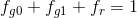 . In our case, since the pre-deformation step is performed at T> Tg, fg0 is almost 0 initially. Both IGP and FGP volume fraction increase as the temperature is cooled down below Tg [66].
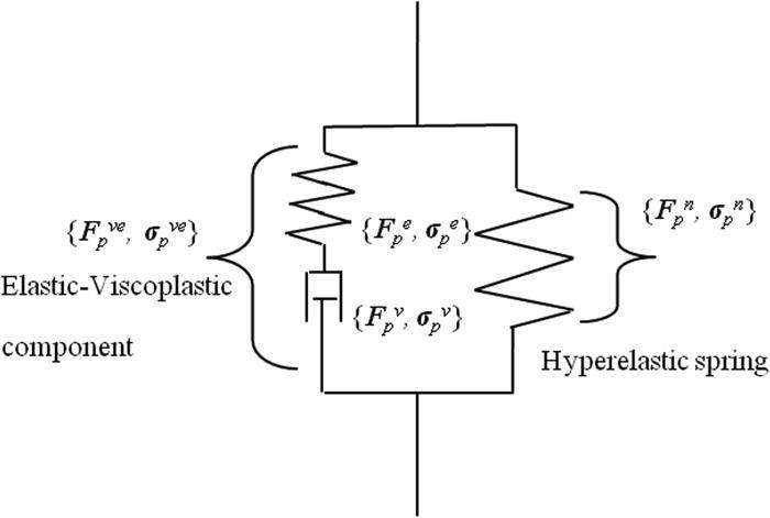 Figure 11. A One Dimensional representation of visco-plastic model of a SMP[146].
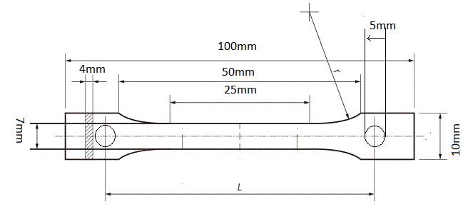 Figure 12: Dog bone shape specimen with dimensions according to ASTM standards.
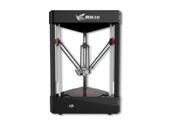 Figure 13: UP 3D printer[174]. Figure 14: Delta 3D [175].
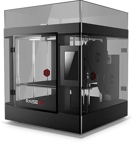 Figure 15: Raise3D N2 3D printer [176].
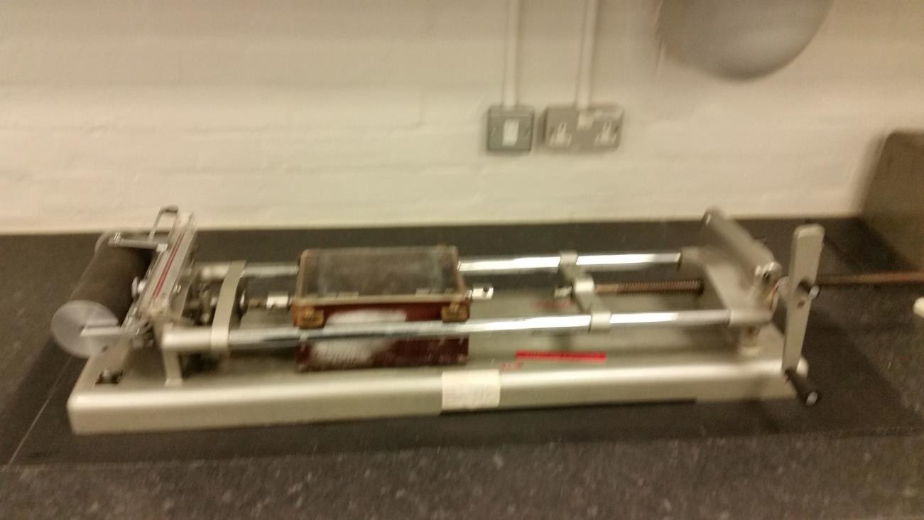 Figure 16: A hand driven Hounsfield Tensometer.
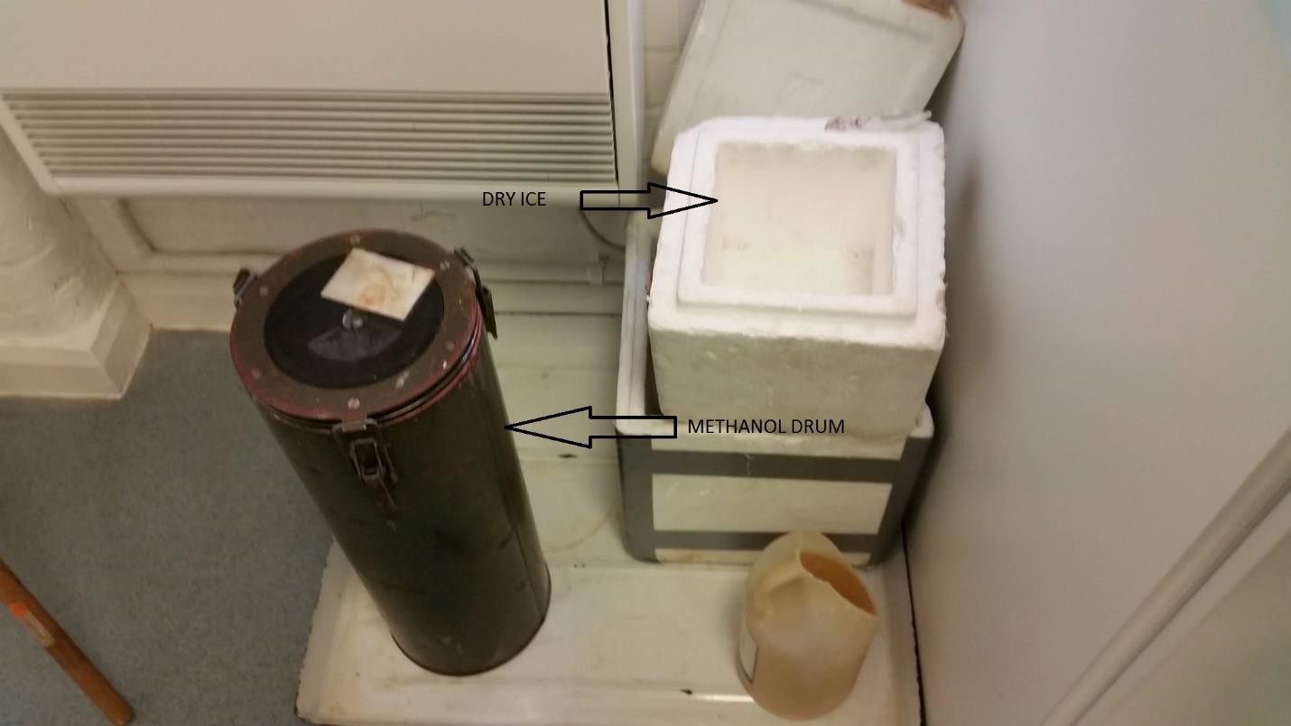 Figure 17: Dry Ice was mixed in the methanol drum to bring it to the desired temperature.
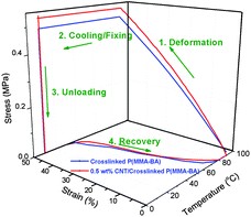 Figure 18
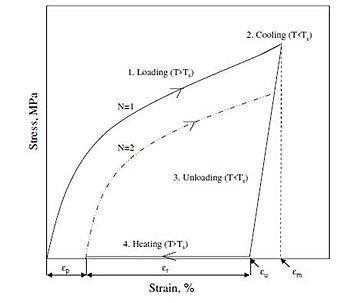 Figure 19
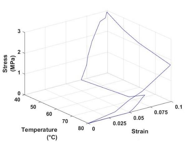
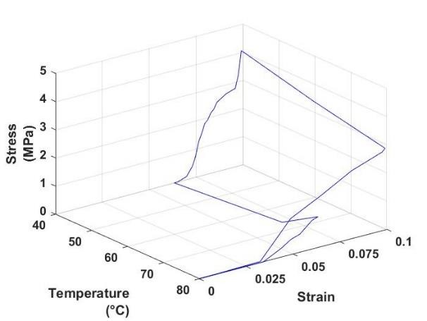
Figure 18. Shows a typical stress-strain temperature curve obtained from a thermo-mechanical tensile test[140].
Figure 19. shows a typical stress- strain curve obtained from a thermo-mechanical tensile test[141,107].
Figure 19
Figure 18. Shows a typical stress-strain temperature curve obtained from a thermo-mechanical tensile test[140].
Figure 19. shows a typical stress- strain curve obtained from a thermo-mechanical tensile test[141,107].
Table 2: TPU test matrix.
 (a) (b)
 (c) (d)
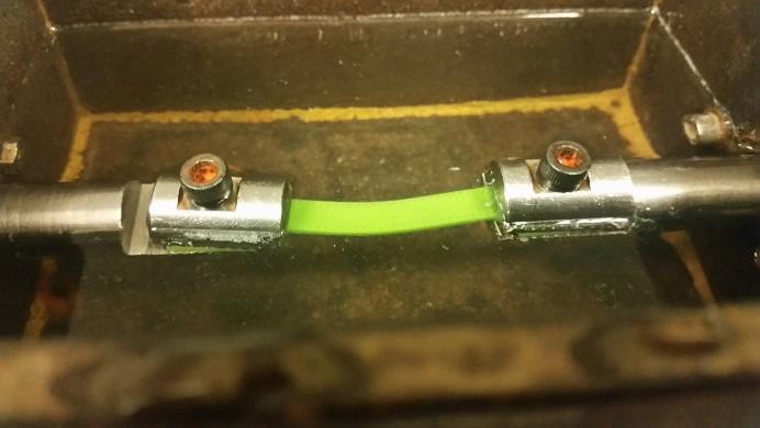
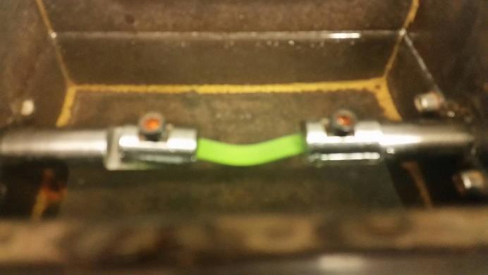
Figure 21: Illustrates the SME in TPU specimens after being compressed to half its length.
(c) (d)
Figure 21: Illustrates the SME in TPU specimens after being compressed to half its length.
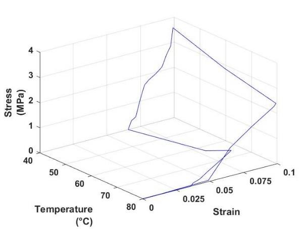
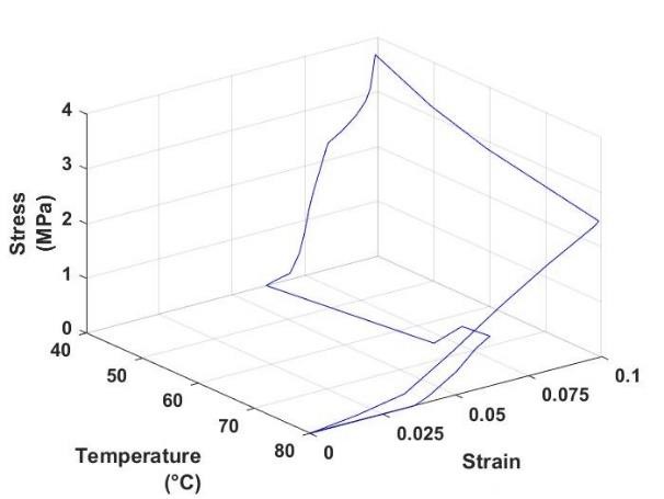
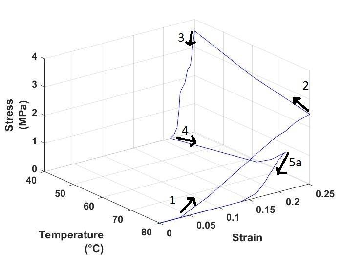 Figure 23: Stress-strain temperature graph of Constrained recovery test at 25% strain, cycle 1, for PLA.
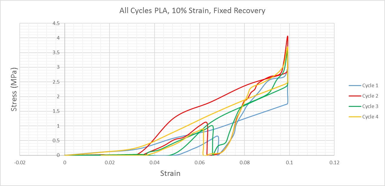 Figure 24: 2-D stress-strain graph of all cycles for PLA at 10% strain constrained recovery test.
Table 3: Critical stresses (in Mpa) for constrained recovery tests of PLA (MPa).

Table 4: Young’s modulus(in Mpa) at rubbery and glassy state for constrained recovery tests of PLA (MPa).

Table 5: Shape fixity ratio for constrained recovery tests of PLA.
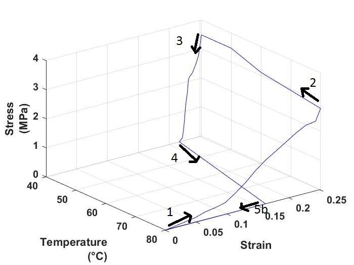 Figure 25: Stress-strain temperature graph of free recovery test at 25% strain, cycle 1, for PLA.
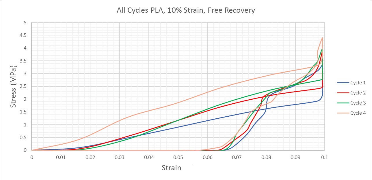 Figure 26: 2-D stress-strain graph of all cycles for PLA at 10% strain free recovery test.

Table 6: Critical stresses (in Mpa) for free recovery tests of PLA.

Table 7: Young’s modulus (in Mpa) at rubbery and glassy state for free recovery tests of PLA.
Table 8: Shape fixity ratio for constrained recovery tests of PLA.
Table 9: Shape recovery ratios for free and Constrained recovery tests of PLA.
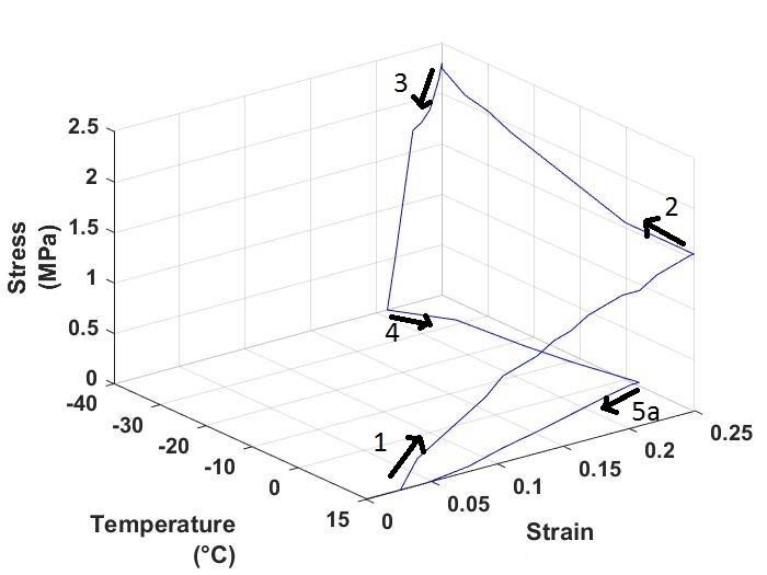 Figure 27: Stress-strain temperature graph of Constrained recovery test at 25% strain, cycle 1, for TPU.
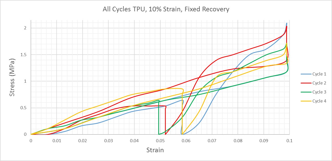 Figure 28: 2-D stress-strain graph of all cycles for TPU at 10% strain constrained recovery test.
Table 10: Critical stresses (in Mpa) for constrained recovery tests of TPU.
 Table 11: Young’s modulus (in Mpa) at rubbery and glassy state for constrained recovery tests of TPU
Table 12: Shape fixity ratio for constrained recovery tests of TPU.
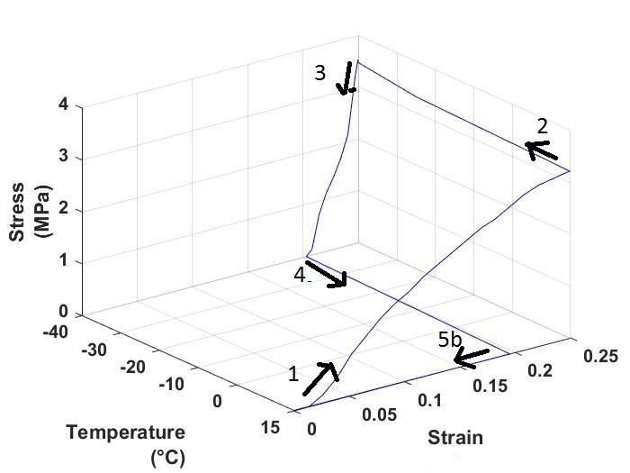 Figure 29: Stress-strain temperature graph of free recovery test at 25% strain, cycle 1, for TPU.
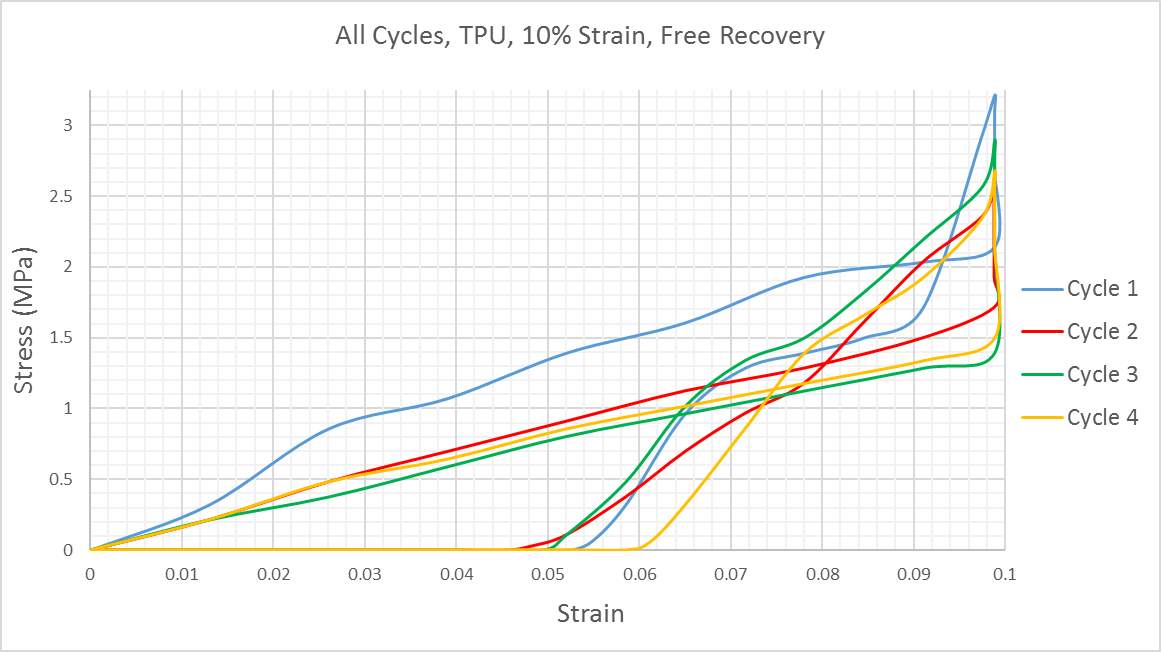 Figure 30: 2-D stress-strain graph of all cycles for TPU at 10% strain free recovery test.
 Table 13: Critical stresses (in Mpa) for free recovery tests of TPU.
 Table 14: Young’s modulus (in Mpa) at rubbery and glassy state for free recovery tests of TPU.
Table 15: Shape fixity ratio for constrained recovery tests of TPU.
Table 16: Shape recovery ratios for free and Constrained recovery tests of TPU.
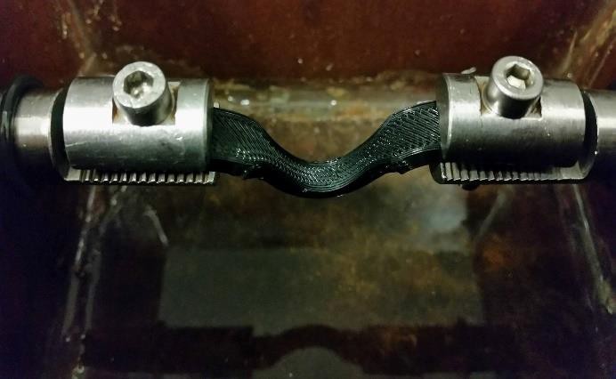
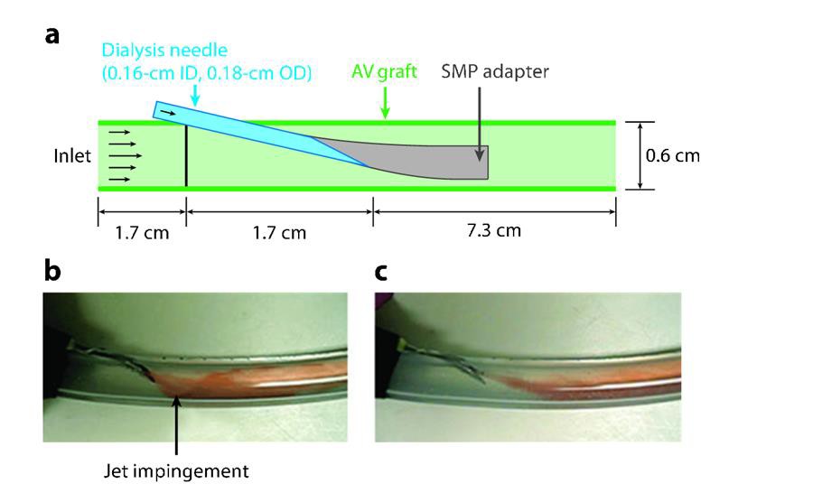 Figure 31: (a) shape memory polymer adapter design with tubular adapter deployed.(b) flow visualization without SMP adapter and flow visualization with SMP adapter (c). ID, OD and AV means inner diameter, outer diameter and arteriovenous respectively [168].
An ingenious dialysis needle adapter with a fixed SMP tube was developed by Ortega et. Al. [168]. This adapter is threaded through the dialysis needle and thermally expanded via blood contact to reach an equilibrium as shown in figure 31. Following dialysis, the SMP adapter is retracted back through the dialysis needle.
An interesting application involving magnetite filled-SMP was developed by schimdt [167] for tumor therapy. The SMP is inserted via minimally invasive surgery near the tumor. Following this, localized treatment is carried out, thus preventing unwanted heating of the surrounding healthy tissues as
Figure 31: (a) shape memory polymer adapter design with tubular adapter deployed.(b) flow visualization without SMP adapter and flow visualization with SMP adapter (c). ID, OD and AV means inner diameter, outer diameter and arteriovenous respectively [168].
An ingenious dialysis needle adapter with a fixed SMP tube was developed by Ortega et. Al. [168]. This adapter is threaded through the dialysis needle and thermally expanded via blood contact to reach an equilibrium as shown in figure 31. Following dialysis, the SMP adapter is retracted back through the dialysis needle.
An interesting application involving magnetite filled-SMP was developed by schimdt [167] for tumor therapy. The SMP is inserted via minimally invasive surgery near the tumor. Following this, localized treatment is carried out, thus preventing unwanted heating of the surrounding healthy tissues as
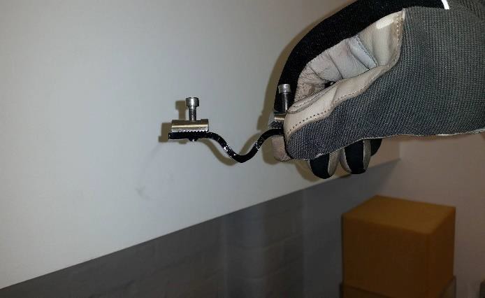
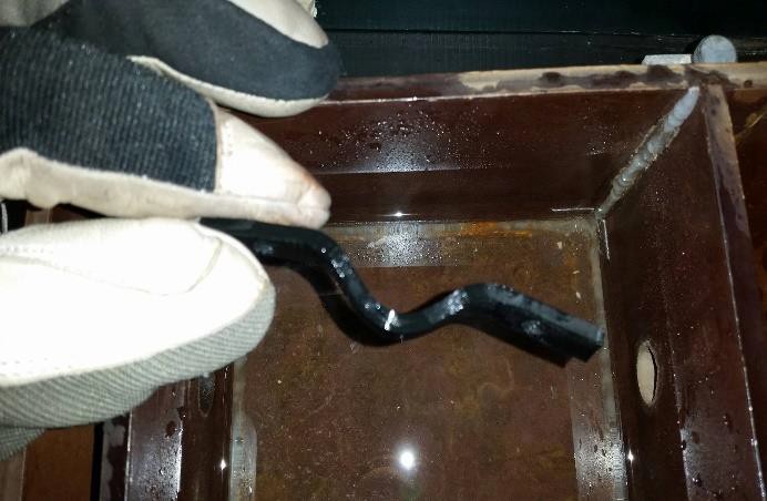
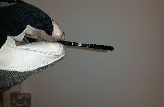
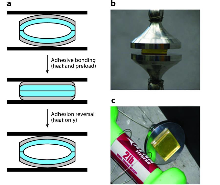 Figure 32: epoxy based SMP (blue) reversible adhesion with pressure sensitive adhesive. (b) SMP in fixed state and SMP in curved shape (c) after thermally induced shape recovery [170].
In terms of structural applications a self-peeling reversible adhesive using an epoxy-based SMP was developed by Xie and Xao [170]. As shown in figure 32, in stress free state the SMP is chosen to be in curved shape, applying pressure above Tg results in a very high pull-off strength(60kPa) and reheating it above Tg triggered SME in SMP causing self-peeling of the adhesive. This process can by repeated multiple times and hence is a new achievement in the field of dry adhesives.
Figure 32: epoxy based SMP (blue) reversible adhesion with pressure sensitive adhesive. (b) SMP in fixed state and SMP in curved shape (c) after thermally induced shape recovery [170].
In terms of structural applications a self-peeling reversible adhesive using an epoxy-based SMP was developed by Xie and Xao [170]. As shown in figure 32, in stress free state the SMP is chosen to be in curved shape, applying pressure above Tg results in a very high pull-off strength(60kPa) and reheating it above Tg triggered SME in SMP causing self-peeling of the adhesive. This process can by repeated multiple times and hence is a new achievement in the field of dry adhesives.
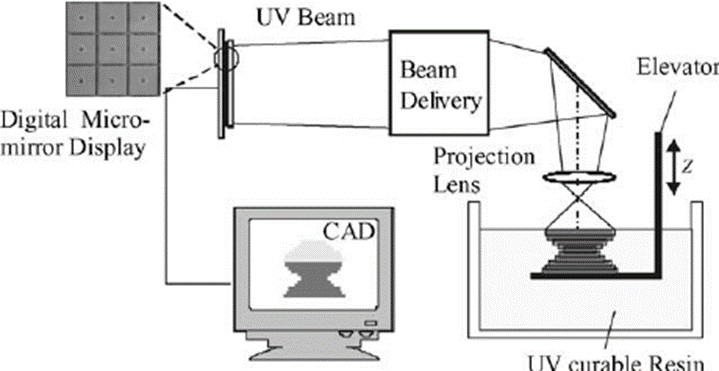 Figure 33. shows a typical micro-stereolithography process [163].
Another topic for research is 3D printing of materials using micro-stereolithography. In this process, UV rays are emitted by the light emitted by LEDs are spatially modulated with the patterns of corresponding 2D images and then projected onto the solution of photo-curable SMP as shown in figure 33. Once the illuminated material gets solidified to form a layer, the bed on which the fabricated structure rests is lowered by a set height (which is usually vertical height of one layer), followed by the projection of next layer on to the solution, This process is continued until the entire structure is fabricated[5]. Although recent researches have shown some promising SMPs triggered by photo-illumination, more research is required to actually use these polymers commercially in applications [77-81].
In this report, satisfactory results were obtained from Hounsfield tensometer, but it is not sensitive
Figure 33. shows a typical micro-stereolithography process [163].
Another topic for research is 3D printing of materials using micro-stereolithography. In this process, UV rays are emitted by the light emitted by LEDs are spatially modulated with the patterns of corresponding 2D images and then projected onto the solution of photo-curable SMP as shown in figure 33. Once the illuminated material gets solidified to form a layer, the bed on which the fabricated structure rests is lowered by a set height (which is usually vertical height of one layer), followed by the projection of next layer on to the solution, This process is continued until the entire structure is fabricated[5]. Although recent researches have shown some promising SMPs triggered by photo-illumination, more research is required to actually use these polymers commercially in applications [77-81].
In this report, satisfactory results were obtained from Hounsfield tensometer, but it is not sensitive
 [1] MakeUseOf. (2017). 3D Printing Evolves to 4D: Here’s What We Know So Far. [online] Available at: http://www.makeuseof.com/tag/3d-printing-evolves-4d-heres-know-far/ [Accessed 1 Apr. 2017].
[2] From 3D to 4D printing: Shoufangyang.
[3] Ken Gall, Martin Mikulas, Naseem A. Munshi, Fred Beavers and Michael Tupper,"Carbon Fiber Reinforced Shape Memory Polymer Composites", Journal of IntelligentMaterials
and Structures, Vol 11, 877(2000)
[4] Thermal, mechanical and electroactive shapememory
properties of polyurethane (PU)/poly (lactic acid) (PLA)/CNT nanocomposites Mohan Raja1
, Sung Hun Ryu, A.M. Shanmugharaj Department of Chemical Engineering, Kyung Hee University,Yongin,Kyunggi-Do 449-701, SouthKorea
[5] Millsaps, B. (2017). Researchers Create Microstereolithography for 4D Printing, Potential for ImpactsinMedical, Solar & More. [online] 3DPrint.com | The Voice of 3D Printing / Additive Manufacturing.Availableat: https://3dprint.com/147312/microstereolithography-4d-printing/ [Accessed 21 Mar.2017].
[6] Effects of moisture on the thermomechanical properties of a polyurethane shape memory polymerB.Yang, W.M. Huang * , C. Li, L.Li
[7] Stratasys.com. (2017). 4D Printing Technology | Stratasys. [online] Availableat:http://www.stratasys.com/industries/education/research/4d-printing-project [Accessed 2 Apr.2017].
[8] Tibbits, S. and K. Cheung, Programmable materials for architectural assemblyand automation. Assembly Automation, 2012. 32(3): p.216-225
[9] Sun, L. and W.M. Huang, Thermo/moisture responsive shape-memory polymerfor possible surgery/operation inside living cells in future. Materials & Design, 2010.31(5): p.2684-2689
[10] Ge, Q. et al. Multimaterial 4D Printing with Tailorable Shape Memory Polymers. Sci. Rep. 6,31110;doi: 10.1038/srep31110(2016)
[11] J. Zhao, M. Chen, X. Wang, X. Zhao, Z. Wang, Z. Dang, L. Ma, G. Hu and F. Chen, "TripleShapeMemory Effects of Cross-Linked Polyethylene/Polypropylene Blends with Cocontinuous Architecture",ACSApplied Materials & Interfaces, vol. 5, no. 12, pp. 5550-5556,2013.
[12] Shape Memory Polymers Literature Review John A.Hiltz.
[13] Google Books. (2017). Polyurethane Shape Memory Polymers. [online] Availableat:https://books.google.co.in/books?id=cGXRBQAAQBAJ&lpg=PA344&dq=what%20happens%20at%20micro-structural%20level%20in%20SMP&pg=PA345#v=onepage&q&f=true [Accessed 24 Mar.2017].
[14] S J Tey et al 2001 Smart Mater. Struct. 10321
[15] T. Pretsch, "Review on the Functional Determinants and Durability of Shape MemoryPolymers",2017.
[16] H Tobushi et al 2004 Smart Mater. Struct. 13881
[17] J. Hu, Y. Zhu, H. Huang and J. Lu, "Recent advances in shape–memory polymers:Structure,
[1] MakeUseOf. (2017). 3D Printing Evolves to 4D: Here’s What We Know So Far. [online] Available at: http://www.makeuseof.com/tag/3d-printing-evolves-4d-heres-know-far/ [Accessed 1 Apr. 2017].
[2] From 3D to 4D printing: Shoufangyang.
[3] Ken Gall, Martin Mikulas, Naseem A. Munshi, Fred Beavers and Michael Tupper,"Carbon Fiber Reinforced Shape Memory Polymer Composites", Journal of IntelligentMaterials
and Structures, Vol 11, 877(2000)
[4] Thermal, mechanical and electroactive shapememory
properties of polyurethane (PU)/poly (lactic acid) (PLA)/CNT nanocomposites Mohan Raja1
, Sung Hun Ryu, A.M. Shanmugharaj Department of Chemical Engineering, Kyung Hee University,Yongin,Kyunggi-Do 449-701, SouthKorea
[5] Millsaps, B. (2017). Researchers Create Microstereolithography for 4D Printing, Potential for ImpactsinMedical, Solar & More. [online] 3DPrint.com | The Voice of 3D Printing / Additive Manufacturing.Availableat: https://3dprint.com/147312/microstereolithography-4d-printing/ [Accessed 21 Mar.2017].
[6] Effects of moisture on the thermomechanical properties of a polyurethane shape memory polymerB.Yang, W.M. Huang * , C. Li, L.Li
[7] Stratasys.com. (2017). 4D Printing Technology | Stratasys. [online] Availableat:http://www.stratasys.com/industries/education/research/4d-printing-project [Accessed 2 Apr.2017].
[8] Tibbits, S. and K. Cheung, Programmable materials for architectural assemblyand automation. Assembly Automation, 2012. 32(3): p.216-225
[9] Sun, L. and W.M. Huang, Thermo/moisture responsive shape-memory polymerfor possible surgery/operation inside living cells in future. Materials & Design, 2010.31(5): p.2684-2689
[10] Ge, Q. et al. Multimaterial 4D Printing with Tailorable Shape Memory Polymers. Sci. Rep. 6,31110;doi: 10.1038/srep31110(2016)
[11] J. Zhao, M. Chen, X. Wang, X. Zhao, Z. Wang, Z. Dang, L. Ma, G. Hu and F. Chen, "TripleShapeMemory Effects of Cross-Linked Polyethylene/Polypropylene Blends with Cocontinuous Architecture",ACSApplied Materials & Interfaces, vol. 5, no. 12, pp. 5550-5556,2013.
[12] Shape Memory Polymers Literature Review John A.Hiltz.
[13] Google Books. (2017). Polyurethane Shape Memory Polymers. [online] Availableat:https://books.google.co.in/books?id=cGXRBQAAQBAJ&lpg=PA344&dq=what%20happens%20at%20micro-structural%20level%20in%20SMP&pg=PA345#v=onepage&q&f=true [Accessed 24 Mar.2017].
[14] S J Tey et al 2001 Smart Mater. Struct. 10321
[15] T. Pretsch, "Review on the Functional Determinants and Durability of Shape MemoryPolymers",2017.
[16] H Tobushi et al 2004 Smart Mater. Struct. 13881
[17] J. Hu, Y. Zhu, H. Huang and J. Lu, "Recent advances in shape–memory polymers:Structure,
 A1.(a) PLA at 10% strain Cycle 1. A1.(b) PLA at 10% strain Cycle 2.
 A1.(c) PLA at 10% strain Cycle 3. A1.(d) PLA at 10% strain Cycle 4.
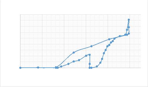
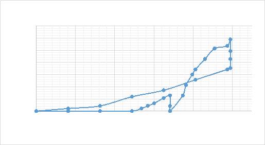 Figure A1.(e) PLA at 10% strain cycle 1.
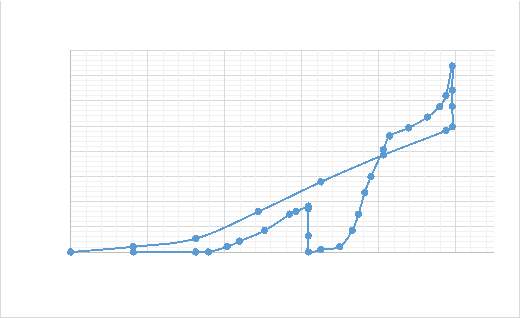
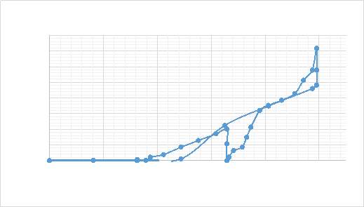 Figure A1.(g) PLA at 10% strain cycle 3.
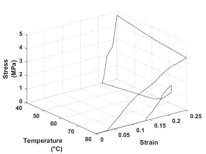 Figure A2. (a) PLA at 25% strain cycle 2.
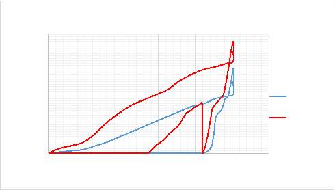
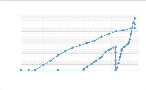 Figure A2.(c) PLA at 25% strain cycle 2.
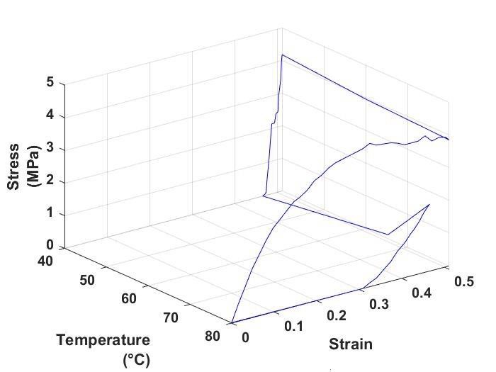 Figure A3. (a) PLA at 50% strain cycle 1.
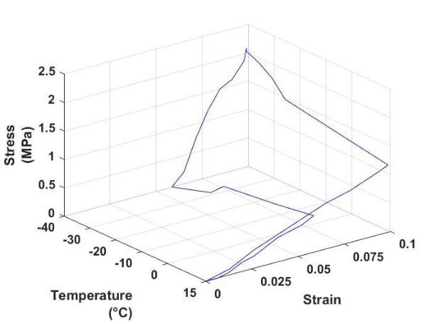
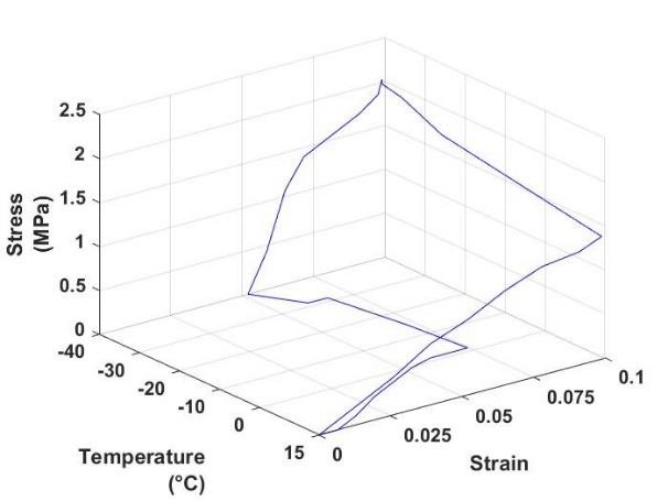 Figure A4. (a) TPU at 10% strain cycle 1. Figure A4. (b) TPU at 10% strain cycle 2.
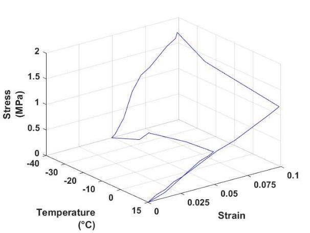
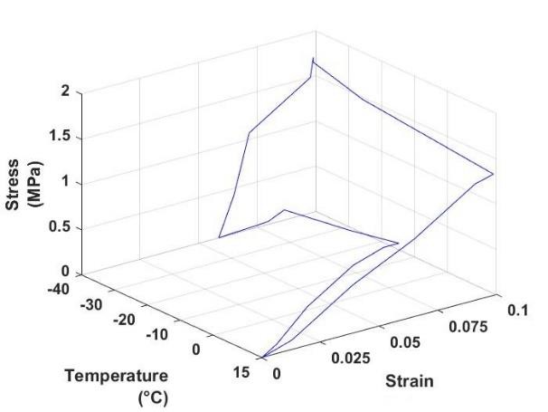 Figure A4. (c) TPU at 10% strain cycle 3. Figure A4. (d) TPU at 10% strain cycle 4.
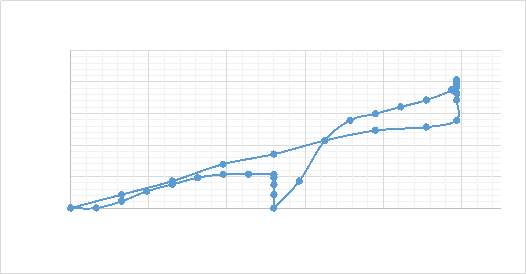 Figure A4. (e) TPU at 10% strain cycle 1.
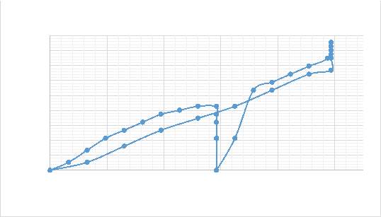
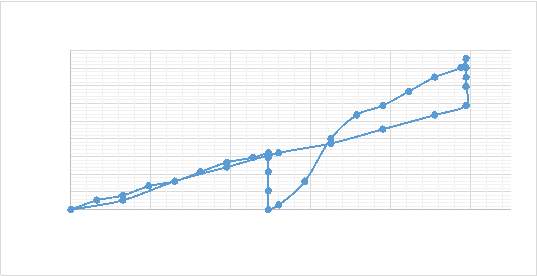 Figure A4. (g) TPU at 10% strain cycle 3.
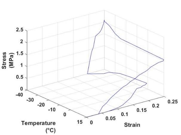
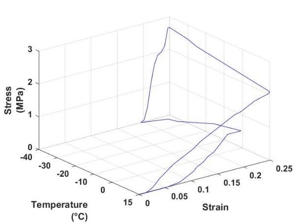 Figure A5. (a) TPU at 25% strain cycle 2. Figure A5. (b) TPU at 25% strain cycle 3.
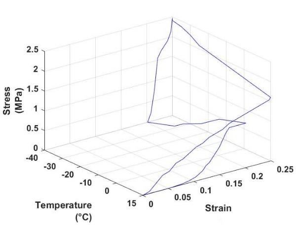 Figure A5. (c) TPU at 25% strain cycle 4.
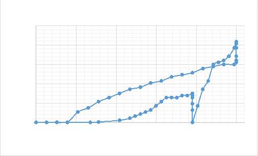 Figure A5. (d) TPU at 25% strain cycle 1.
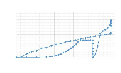
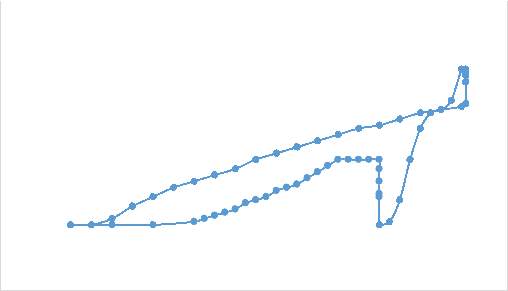 Figure A5. (f) TPU at 25% strain cycle 3.
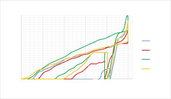 Figure A5. (h) TPU at 25% strain all cycles.
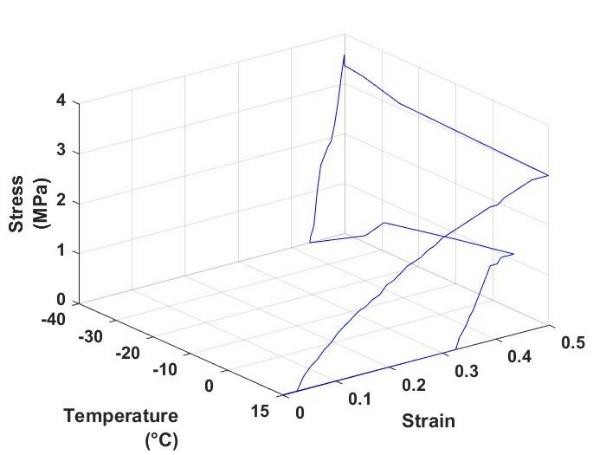
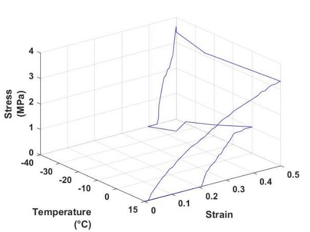 Figure A6. (a) TPU at 50% strain cycle 1. Figure A6. (b) TPU at 50% strain cycle 2.
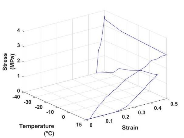
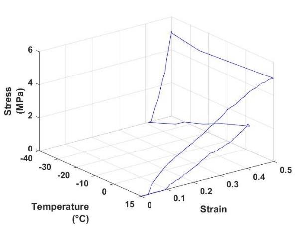 Figure A6. (c) TPU at 50% strain cycle 3. Figure A6. (d) TPU at 50% strain cycle 4.
 Figure A6. (e) TPU at 50% strain cycle 1.
 Figure A6. (g) TPU at 50% strain cycle 3.
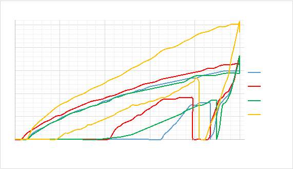 Figure A6. (i) TPU at 50% strain all cycles.
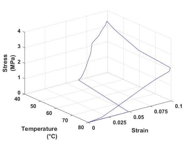
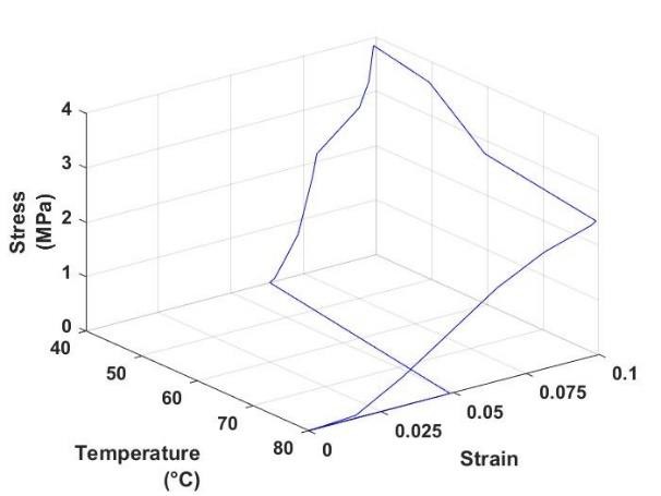 Figure B1. (a) PLA at 10% strain cycle 1. Figure B1. (b) PLA at 10% strain cycle 2.
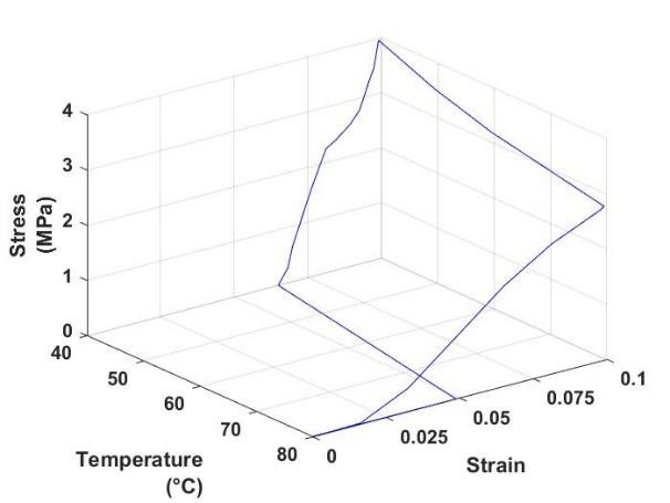
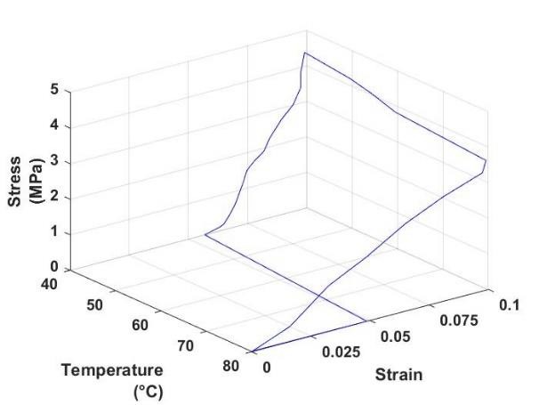 Figure B1. (c) PLA at 10% strain cycle 3. Figure B1. (d) PLA at 10% strain cycle 4.
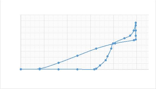 Figure B1. (e) PLA at 10% strain cycle 1.
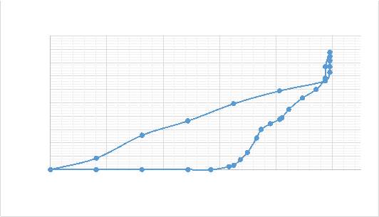
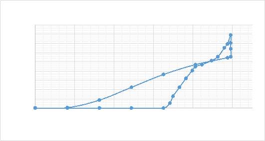 Figure B1. (g) PLA at 10% strain cycle 3.
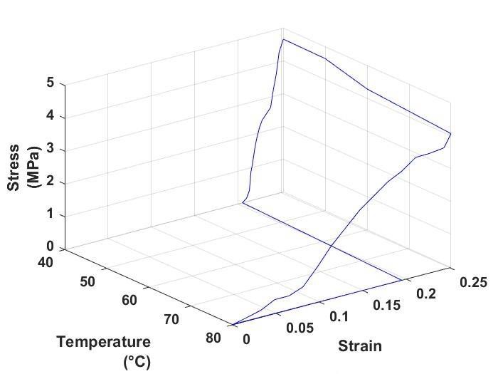 Figure B2. (a) PLA at 25% strain cycle2.
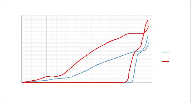
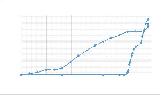 Figure B2. (c) PLA at 25% strain cycle2.
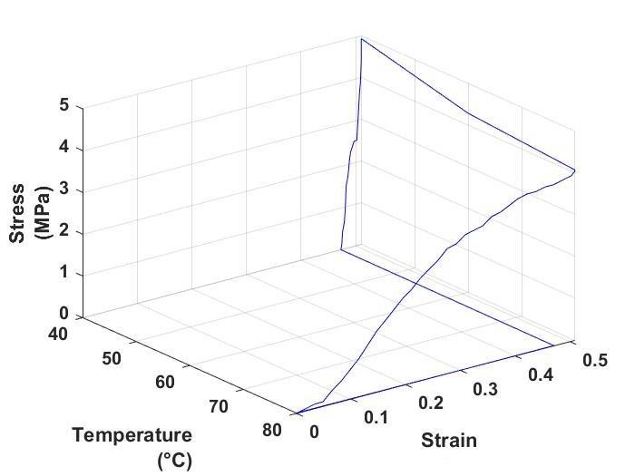 Figure B3. (a) PLA at 50% strain cycle 1.
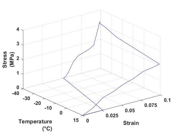
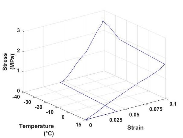 Figure B4. (a) PLA at 10% strain cycle 1. Figure B4. (b) PLA at 10% strain cycle 2.
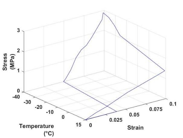
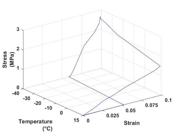 Figure B4. (c) PLA at 10% strain cycle 3. Figure B4. (d) PLA at 10% strain cycle 4.
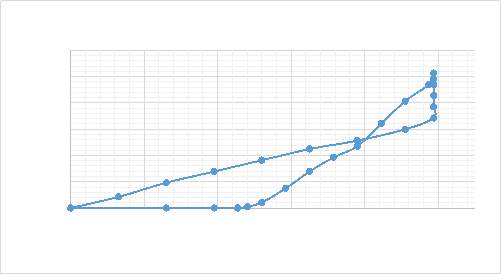 Figure B4. (e) PLA at 10% strain cycle 1.
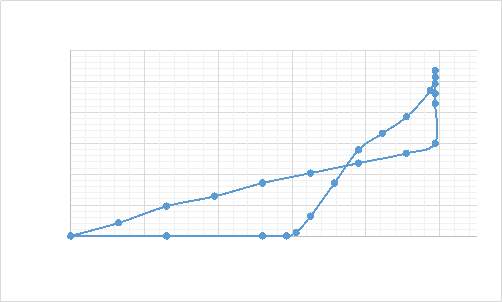
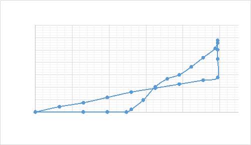 Figure B4. (g) PLA at 10% strain cycle 3.
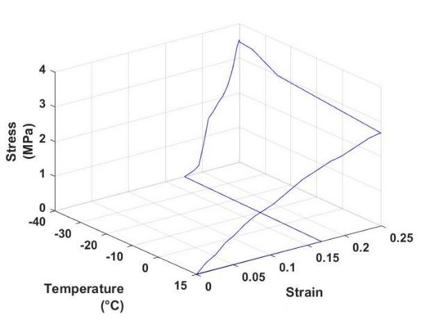
 Figure B5. (a) TPU at 25% strain cycle 1. Figure B5. (b) TPU at 25% strain cycle 2.
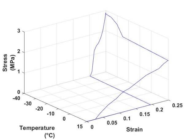 Figure B5. (c) TPU at 25% strain cycle 3.
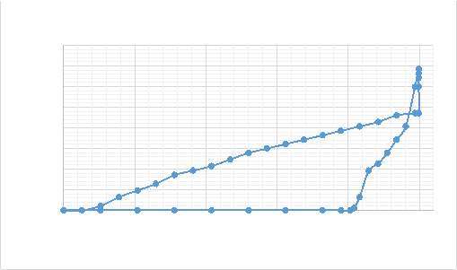
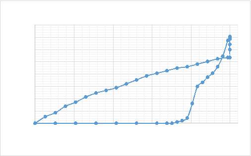 Figure B5. (f) TPU at 25% strain cycle 2.
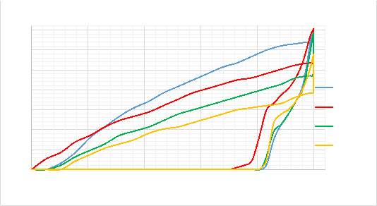
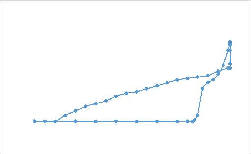 Figure B5. (h) TPU at 25% strain cycle 4.

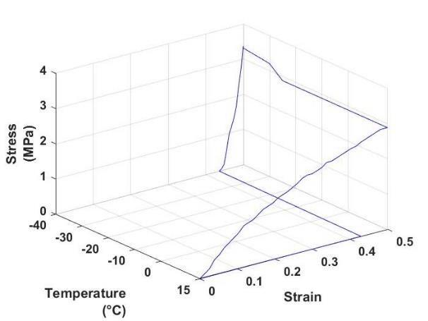 Figure B6. (a) TPU at 50% strain cycle 1. Figure B6. (b) TPU at 50% strain cycle 2.
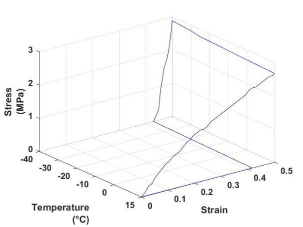
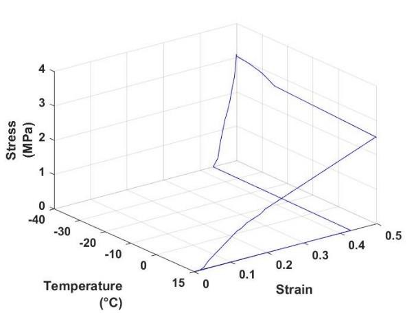 Figure B6. (c) TPU at 50% strain cycle 3. Figure B6. (d) TPU at 50% strain cycle 4.
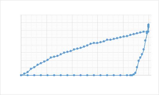 Figure B6. (e) TPU at 50% strain cycle 1.
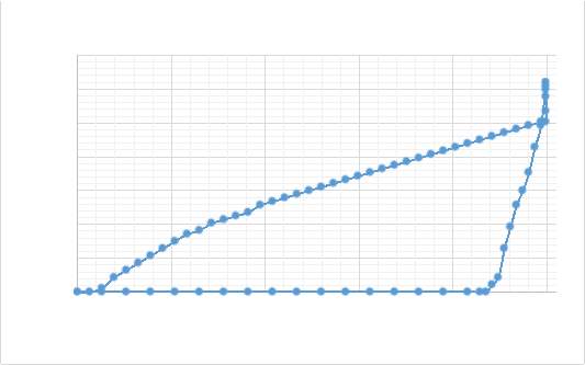
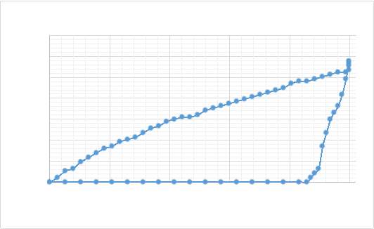 Figure B6. (g) TPU at 50% strain cycle 3.
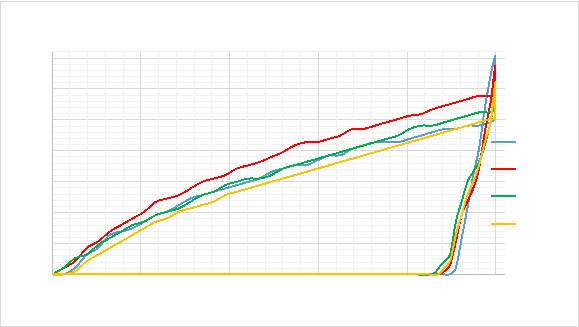 Figure B6. (i) TPU at 50% strain all cycles.


While 3D printing is gaining popularity all over the globe, the term 4D printing has been coined recently by Skylar Tibbits, a renowned American designer and computer scientist, which has opened a wide spectrum of new possibilities and applications specially in Aerospace and Healthcare sector. The 4th dimension in 4D printing is time and only a certain class of material known as "smart material" can be 4D printed. These smart materials can be classified into two categories shape memory polymers and shape memory alloys. This report aims to demonstrate the shape memory effects and record the stress- strain data in shape memory polymers such as Thermoplastic Polyurethane (TPU) and poly-lacticacid (PLA) when it is put through a typical programming - recovery cycle and hence conclude which polymer is more suitable for bio-medical applications. Apart from being cheap and readily available in 3D printable filaments the main purpose for choosing TPU and PLA as basis of this study was their excellent bio-compatibility which makes them attractive materials for biomedical applications.
In order to investigate thermo-mechanical and shape recovery properties of both the shape memory polymers a series of cyclic thermo-mechanical tensile tests at strain 10%, 25%, 50% were conducted. 3D printed test specimens of both PLA and TPU deformed equally under axial loading but exhibited different rate of recovery and strain recovery ratio. The report also demonstrates what changes occur in the shape memory properties of both the shape memory polymers as the number of cycles on same strain were increased. The results for both the polymers were recorded and compared. It was found that TPU underwent complete recovery at all strains and in all the cycles when heated above its glass transition temperature. On the other hand PLA was able to fully recover in all cycles when the strain was 10% but failed to last more than 3 and 2 thermo-mechanical tensile cycles at 25% and 50% strain respectively.
In order to achieve the purpose of this report Hounsfield tensometer was used to perform tensile tests and UP and Delta 3D printers were used to 3D print TPU and PLA test specimens.
CONTENTS
Declaration of Authorship ……………………………………………………………………………………………………….1 Abstract……………………………………………………………………………………………………………………………………2 Contents…………………………………………………………………………………………………………………………………3-4 Acknowledgements………………………………………………………………………………………………………………….5 Nomenclature………………………………………………………………………………………………………………………….6
1. Introduction………………………………………………………………………………………………………………….7 2. Evolution of 4D printing…………………………………………………………………………………………….7-8 3. Literature Review………………………………………………………………………………………………………….8 3.1 General Concept of Shape memory polymers……………………………………………………8-10 3.1.1 Training and Characterization of SMPs……………………………………………………...9-10 3.2 History…………………………………………………………………………………………………………………11 3.3 Classifications of SMPs………………………………………………………………………………………12-13 3.4 Structure and mechanisms of SMP…………………………………………………………………….13-16 3.5 Effect of training variables on shape memory effect……………………………………………..17 3.6 Cyclic Actuation…………………………………………………………………………………………………17-18 3.7 Multi – Functional SMPs……………………………………………………………………………………. 18 3.8 Triple Shape memory effects…………………………………………………………………………….18-19- Advantages of Shape Memory Polymers………………………………………………………………19
- Constitutive model for shape memory polymer behavior……………………………20-21
5.4.2 TPU test procedure……………………………………………………………………………………28
6. Results and Discussion…………………………………………………………………………………………….31-49
6.1 Results……………………………………………………………………………………………………………….31-46
6.1.1 PLA results……………………………………………………………………………………………34-40
6.1.1.1 Constrained recovery tests……………………………………………………………34-36 6.1.1.2 Free Recovery tests…………………………………………………………………………37-40
6.1.2 TPU test Results……………………………………………………………………………………41-46 6.1.2.1 Constrained recovery tests……………………………………………………………..41-43 6.1.2.2 Free recovery tests………………………………………………………………………….44-46
6.2 Discussion………………………………………………………………………………………………………...46-48
6.2.1 In terms of Shape fixity and Shape recovery ratio…………………………………48
7. Applications…………………………………………………………………………………………………………….49-51
7.1 Medical Applications…………………………………………………………………………………………49-50
7.2 Space Applications……………………………………………………………………………………………….50
7.3 Textile Applications………………………………………………………………………………………………50
7.4 Structural Applications…………………………………………………………………………………………51
8. Future Work……………………………………………………………………………………………………………52-53
9. Conclusion………………………………………………………………………………………………………………53-54 References……………………………………………………………………………………………………………………54-69 Appendix A…………………………………………………………………………………………………………………..70-86 1.Constrained Recovery Thermo-mechanical tensile tests for PLA…………………………..70-75 2.Constrained Recovery Thermo-mechanical tensile tests for TPU………………………….76-86
Appendix B………………………………………………………………………………………………………………..87-104 1.Free Recovery Thermo-mechanical tensile tests for PLA………………………………………87-94 2.Free Recovery Thermo-mechanical tensile tests forTPU…………………………………….95-104 Appendix C……………………………………………………………………………………………………………….105-110
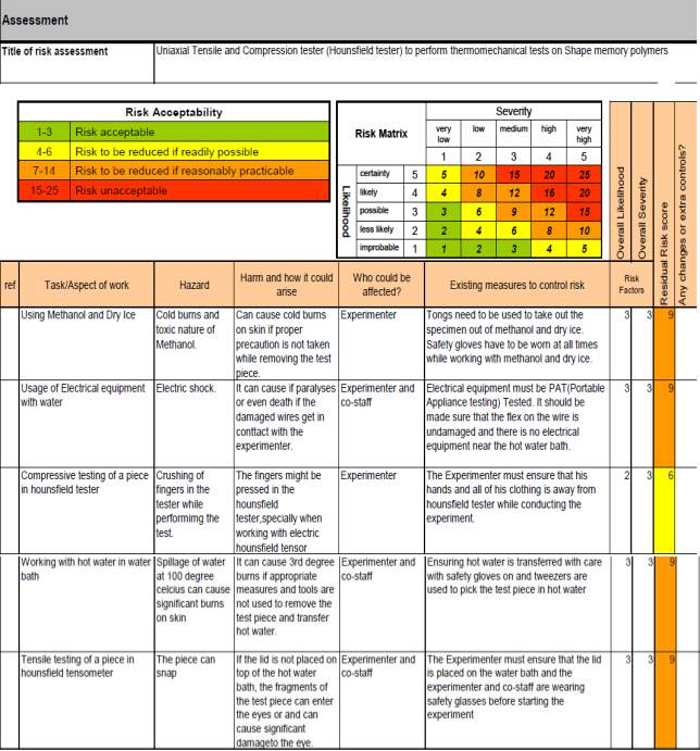
1. Risk Assesment……………………………………………………………………………………………..105-107
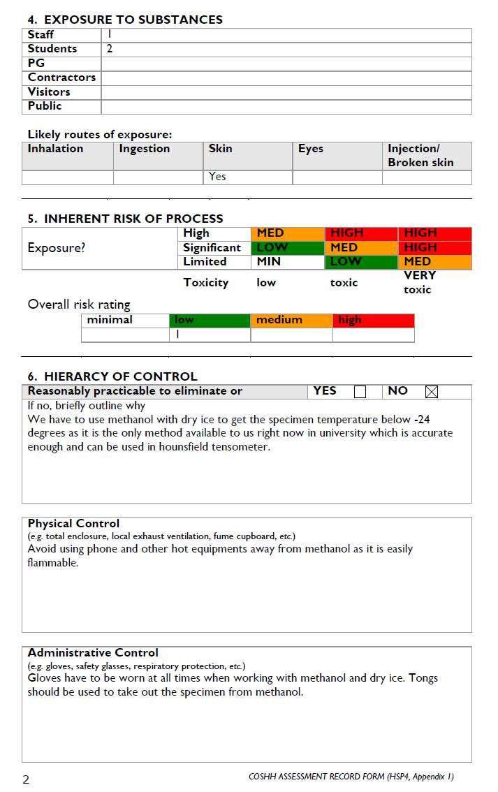
2. COSHH Form…………………………………………………………………………………………………108-110
AKNOWLEDGEMENTS
Samarth Jain
I would like to thank my supervisor, Dr Brian G Mellor for constantly guiding me through the course of this project. I would also like to thank Mr. Dave Beckett, chief technician in the Materials laboratory at university of Southampton, for helping me during the experimental phases of this project. I would also like to extend my gratitude towards my parents who have been a constant support during this project. Completing this research project has been a challenging and enlightening endeavor, which I couldn’t have achieved without the support mentioned above.
NOMENCLATURE
SMP Shape memory polymer
SME Shape memory effect
PLA Poly-lactic acid
TPU Thermo-plastic Polyurethane
Tg Glass transition temperature
Tm Melting Temperature
εp Applied Strain
εu Prescribed Strain
εir Irreversible Strain
Erubber Young’s modulus in loading path
Eglassy Young’s modulus in unloading path
σmax Max stress at the end of the loading path
σthermal Stress on cooling test piece after loading
σrecovery Recovery stress
1. INTRODUCTION
4D printing is very similar to 3D printing in the sense that it still uses additive manufacturing to create objects which come out looking the same to the ones that are 3d printed, the only difference is that 4D printing involves materials that eventually switch their geometric configuration in a fully controllable manner after a reaction to different properties or triggers[1]. Another requirement for 4D printing is that there should be at least two structurally stable geometric configurations in a 3d printed item when subjected to the right stimulus before and after [2]. Materials such as Ceramics, Polymers and Metal alloys are capable of recovering from mechanically and thermally induced strain when subjected to an external stimuli and are hence known as shape memory materials [3]. Most of the shape memory materials use temperature as external stimulus but in some materials shape memory effect can also be triggered by light, magnetism, humidity or electricity [4][5][6][29,30]. In this report we will be focusing on Shape memory Polymers that are thermo-sensitive as they have more potential to be used in bio-medical applications because of their glass transition temperature being closer to the human body temperature [4]. For any polymer to be classified as shape memory polymer it should be elastically deformable and thermal sensitive and therefore shape memory properties are not intrinsic to polymers [31]. PLA and TPU specimens used in this study were 3d printed in a typical dog bone shape and in lay flat position using UP, Raise3D N2 , and delta 3d printer respectively.2. EVOLUTION OF 4D PRINTING
A unique research collaboration between Stratasys Education's R&D department and Self Assembly Lab of MIT led to the development of a process called 4D printing[7]. This unique research was led by Skylar Tibbits and focused on developing self-assembling technologies[7]. Tibbit' s initial 4d printing project was only made possible because of Connex multi-material 3d printing Technology. This technology printed materials with different water absorbing capabilities and hence the printed object changed shape when immersed in water. Fundamentally, it has been found that there are several techniques/approaches which are capable of realizing 4d printing, namely deployable mechanism/structure, bi-stable structure, compliant mechanism, (active) assembly/disassembly, stimulus induced deformation mis-match and shape memory effect based technology[2][7].
Self-Assembly Components are 3d printed components which automatically assemble/dissemble when a certain stimulus is applied. This is a relatively new concept and requires careful designing of the components that have to be assembled[8-9].
Deformation mis-match is usually observed in bi-layered structures where the layers have difference in some of their physical properties such as thermal expansion coefficient.On heating a piece of bi-layered beam tends to bend towards one direction more than the other and hence this can induce folding and unfolding of structures[32-36].
Bi-stability is a characteristic of a the 3d printed structure which under certain conditions may have two or more stable positions, and the structure is capable of switching from one stable position to the other when it is subjected to right stimulus[37,38].
When a shape memory material, in the presence of right stimulus, is quasi-plastically deformed; it comes back to its original shape in which it was 3d printed. This is known as shape memory effect[39].
Numerous investigations have been made on finding different ways to 3d print shape memory polymers at micron level and out of all of them projection micro-stereolithography (PμSL) based additive manufacturing shows real promise[10]. Micro-stereolithography uses high resolution projection of Ultra- Violet (UV) rays emitted by a light emitting diode (LED) onto a photo-curable shape memory polymer[5].
3. LITERATURE REVIEW
3.1 General Concept of Shape memory polymers
Permanent Shape of the shape memory polymers can be set by 3d printing. Deformation can be imposed by heating the specimen above Tg and stretching/compressing it. After deforming the test specimen, it can be quickly cooled down to temperature below Tg to fix that temporary shape. This temporary shape can be generally maintained until the shape memory effect is activated by an external stimuli after which the SMP would recover its permanent shape[1]. Fundamentally, this happens because SMPs generally consist of two different domains namely the fixed domain that is responsible for keeping the permanent shape and is typically chemical or physical cross- linking points in a polymer, and the second one is reversible domain which is used to form the temporary shape and is usually an amorphous or a crystalline phase of SMP[12].
Figure 1 Figure 2
Figure 1 shows the difference in variation of the dynamic modulus of a SMP compared to an ordinary polymer[148][141].
Figure 2 shows how the Young's modulus of a SMP changes with temperature[149].
The basis of the shape memory effect in polymeric materials is the large difference between the Young's modulus of the SMP above and below the switching temperature compared to ordinary polymer as shown in figures(1 and 2). The low modulus favors the deformation in glassy state and high modulus favors the fixing of temporary shape at low temperature [12]. For a shape memory polymer to exhibit shape memory effect, the switch temperature (Tsw) of the reversible domain is vital. This switch temperature can be glass transition temperature (Tg) for the amorphous phase or melting temperature (Tm) for the crystalline phase[11].
When the temperature goes above Tsw, the molecular chains in the reversible domain of the SMP become mobile and can be easily deformed under external load. For example a curled shape can be made straight by stretching it above (Tsw). Then this deformation can be fixed or frozen by cooling it to a temperature below (Tsw) while the test specimen is still under external tension. When the external force is removed, the specimen will retain its temporary shape with no loss in strain. Finally when the temperature is again increased above the Tsw, the molecular chains release the deformation and recover back to their permanent shape due to their high mobility. This mainly happens because the molecular chains in polymers energetically prefer to return to their most disordered conformation[11].
3.1.1 Training and Characterization ofSMPs
Shape memory cycle
A typical shape memory cycle as shown in figure (3) below consists of three stages:
Figure 3. shows the programming – recovery shape memory cycle[145].
Programming- The sample is heated above its glass transition temperature and at this elevated temperature the sample is then deformed from point 1 to point 2.
Cooling- The sample is then cooled below its Tg at constant load. At low temperatures the load is removed and shape fixity is observed.
Reheating/recovery - Shape recovery is observed when the sample is reheated above its glass transition temperature. A sharp change in strain is observed when the sample is first heated above Tg due to recovery stress and the sample finally stabilizes at strain near the starting strain point. The recovery can be performed with constraints(constrained recovery) and without constraints (free recovery)[73,74].
Shape memory parameters
The shape memory parameters are essential for determining the shape memory performance for a particular SMP. The two most important shape memory parameters are Shape fixity and Shape recovery ratio.Shape fixity
The degree to which the temporary shape is fixed, after the subsequent cooling and unloading following the deformation step, is mainly characterized by the shape fixity ratio Rf and is given by[73-76]: (1)
Here εm is the applied strain and εu(N) is the strain following the removal of the applied stress in Nth cycle.
Shape recovery
Permanent shape recovery is observed when the sample is heated above Tg and the material recovers some portion of its permanent shape. The degree to which the sample recovers its permanent shape is characterized by the shape recovery ratio, Rr, given by [73-76]:
(2)
Here εm and εir are applied and irreversible strains respectively [159].
3.2 History
The term shape memory was first coined by Vernon in 1941. However, the importance of SMPs started increasing after 1960's when PE was being used to make heat shrinkable tubes and films[57,58]. More efforts to develop SMPs began in 1980's and the first poly(norborene) [59]based shape memory polymer was reported by Chimie Company, France, in 1984 and was made commercially availabe later in the same year by Nippon Zeon Company of Japan under the name Norsorex[60]. This SMP has a Tg between 35° and 40°. The second poly(trans-isoprene) based commercial SMP was fabricated by The Kurare Corporation, Japan, in 1987, and had a Tg of -68° and a melting temperature (Tm) of 67°[61]. The third commercial SMP, Asmer, was developed by Asahi company in japan. It is a poly(styrene- butadiene) based polymer whose Tg fluctuates between 60 to 90 degree Celsius[61]. Mitsubishi Heavy Industries developed Diisocyanate/polyol based SMPs in late 1980's followed by polyester polyol based polyurethane and polyether polyol based polyurethane with trade names Diary MM-4510 and Diary MM-4520 respectively[62]. The main advantages of polyurethane SMPs were flexibility in designing materials with a range of Tgs and ease of processability. A series of polyester based SMPs were produced by Nippon Zeon and were marked under the trade name Shable. In 1990's more efforts were put in development and application of thermo-plastic polyurethane based SMPs. The most important reason for this was the ability to control structure and hence properties of poly(urethanes) [63]. To address the issue of low strength and stiffness of SMPs, Liang et.al. proposed the use of shape memory composites in 1997[60]. Polyurethane SMP composites were prepared using chopped glass, woven fiberglass and unidirectional Kevlar. Recently, Numerous investigations involving the fabrication of SMP composites using resin transfer molding and pre-impregnation of fiber rows have been reported. A Tg ranging from -13° to 90° Celsius could be obtained by virtue of controlling the degree of cross- linking within the resin[64].3.3 Classifications of SMPs
SMPs can be classified into various categories based on external stimulus such as thermally induced, light induced, electro-active, water/moisture induced, pH/magnetic/redox-sensitive. In terms of the nature of their net points SMPs can be divided into physically crosslinked and chemically cross linked SMPs[112,115]. Chemically cross-linked polymers are also known as thermosets in which the individual polymeric chains are connected by covalent bonds. For this reason sets soften but do not melt at high temperatures. On the other hand physically cross-linked polymers are also known as thermo-plastics in which crystalline or glassy phases are responsible for bonding between the individual polymeric chains. Thermo-plastic show reversible nature and are easy to shape and reform but can potentially melt at high temperatures and loose their shape memory properties[76]. SMPs can also be subdivided based on their switch type into Tg- type SMPs with an amorphous phase or Tm-type SMPs with a crystalline phase[115]. Figure 4 below presents an integrated insight into classification of SMPs by polymerization, structure, shape memory functionality and stimuli. The composition and structure of SMPs includes chemically cross-linked polymers[98,113,116,117]], segmented or block copolymers[118-121], polymers with interlocked polymeric networks IPNs[122] and Semi-IPNs[123-125], polymer blends[126-128] and composites[129-132], and polymers with supramolecular polymer network[109].Hence, SMPs can be prepared using any polymerisation method such as addition[133], free-radical[109] and photo-chemical polymerisation[113], condensation[134], radiation reaction[135], acyclic diene metathesis (ATMET)[136] and ring open polymerisation (ROMP)[137]. Shape memory polyurethanes (SMPUs) and ethylene-oxide- ethylene terephthalate segmented copolymers are usually prepared through condensation polymerization[134] whereas Cross-linked PE is prepared through radiation reaction. Some SMPs can also be prepared simply blending two polymers or fabricating non-woven fabric composite into an elastomer. Varied shape -memory functions can be achieved by virtue of controlling the composition and polymerization method of a SMP[126,138].
Figure 4. Shows classification of SMPs on the basis of composition, structure, stimuli and SME[143].
The progress in development of SMEs of SMPs have been remarkable. SMPs have developed to show two-way, triple and multiple SMEs. Apart from this biodegradability, multi-functionality( for example: permeable optic, thermo-chronic properties) can also be achieved in SMPs[139].
3.4 Structure and mechanisms of SMP
Shape memory behavior is shown by various polymer systems which are significantly different from each other in terms of molecular structure and morphology. Some of the conventional SMP systems include cross-linked PE and PE/nylon 6 graft co-polymers[90,91]], trans-polyisoprene (TPI)[92], styrene- based[94,95], acrylate-based[96], thio-ene-based [100] and epoxy-based polymers[99], cross-linked ethylene vinyl acetate copolymer[93] and polycycJooctene[98], polynorborene[97], segmented
polyurethane (PU)[105,101] and its ionomers[102,103]. Numerous reports have also been made for some new bio-polymers such as poly(3-hydroxyalkanoate)s (PHAs)[104] and bile-acid-based polyesters[106] that exhibit SME but further optimization is required for their shape memory properties to be desirable in applications.
Several types of structures and programming models have been proposed to demonstrate the underlying mechanism for SME in SMPs. Figure 5 below illustrates the progress in models developed to explain the mechanism of thermal sensitive SMPs. From figure 5a we can see that in chemical cross- linked semi-crystalline PE, the crystalline phase with a crystal melting temperature (Tm) acts as a switch unit to provide the shape fixity capacity[90]. following this, the general molecular mechanism of thermal-sensitive SMPs was proposed (Fig 5b), in this the network structure is either physically or chemically cross-linked and amorphous or semi-crystalline phase acts as switch units[107,106].
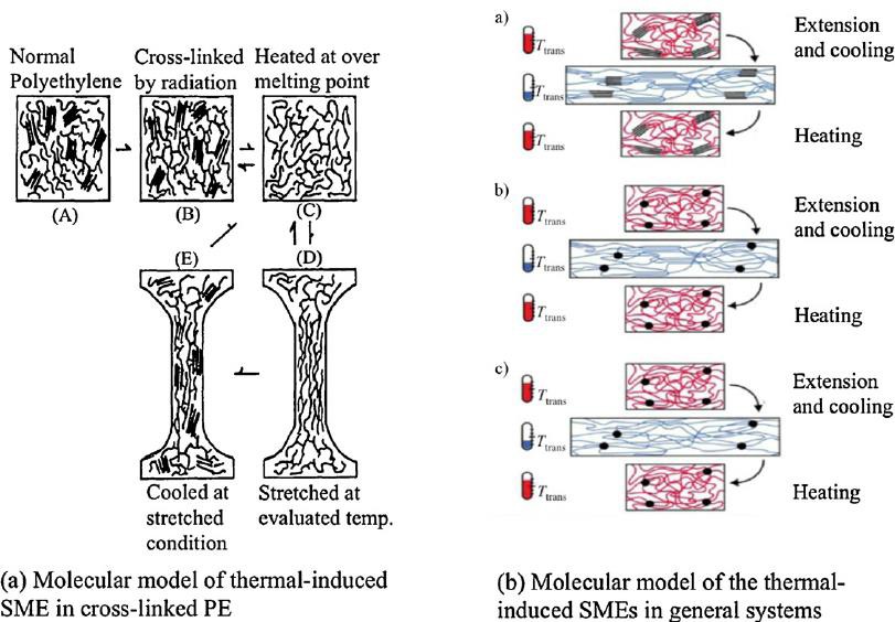 Figure 5: general molecular models of thermos-sensitive SMPs [90,107].
Figure 5. Supramolecular SMP systems [109,110].
Figure 5: general molecular models of thermos-sensitive SMPs [90,107].
Figure 5. Supramolecular SMP systems [109,110].
Figure 5: general molecular models of thermos-sensitive SMPs [90,107].
Figure 5. Supramolecular SMP systems [109,110].
Finally, a simple but comprehensive model for 3D SMP architecture, capable of describing the underlying mechanism of any SMP polymer, was proposed by Hu and Chen (Fig. 6)[111]. According to this model SMPs consist of both switch units and net points. The net points can be made of either chemical or physical cross-links, with an interlocked supramolecular complex, and are responsible for determining the permanent shape. Entropic elasticity of the polymeric network serves as the driving force for strain recovery in SMPs. Similarly, shape fixity and shape recovery is driven by the switch units upon application of a predetermined external stimulus.
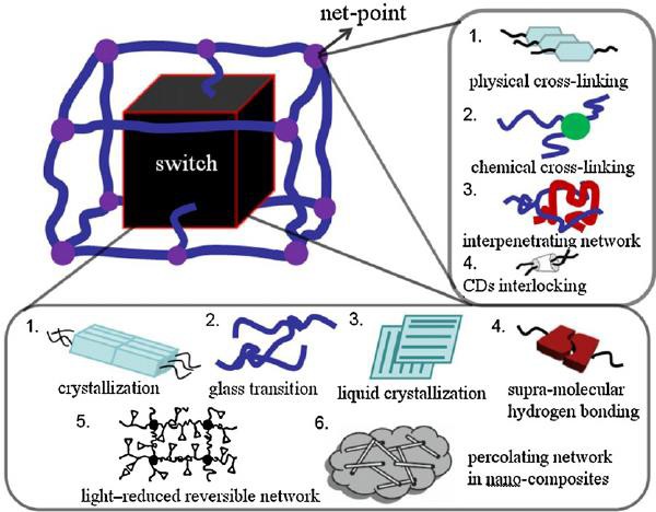 Figure 7: Overall architecture of different types of SMPs [143].
Until now in thermal-sensitive SMPs, amorphous, crystalline and supramolecular entities have served as switch units and in all of these systems, entropic elastic force results from polymeric network. Hence in all SMPs physical or chemical net-points via intermolecular forces or covalent bonding are required.
Figure 7: Overall architecture of different types of SMPs [143].
Until now in thermal-sensitive SMPs, amorphous, crystalline and supramolecular entities have served as switch units and in all of these systems, entropic elastic force results from polymeric network. Hence in all SMPs physical or chemical net-points via intermolecular forces or covalent bonding are required.
Figure 8. Molecular structure of a typical Polyurethane SMP depicting hard and soft segments in it[144].
3.5 Effect of training variables on shape memory effect
The stability of SME in a SMP over its entire life cycle is very vital when considering applications of SMPs. There are several factors that determine the long-term stability of shape memory effect : From a design point of view, different 3d printing/assembly configurations of SMPs and conventional materials affect the loads acting on a 3d printed structure. Therefore, long-term SME stability studies should be conducted based on the exact loading needs. In addition to this Environmental conditions in which an SMP operates also play a very vital role in determining long-term SME stability[14,15]. Performance of an SMP in terms of its shape fixity and shape recovery ratio is very much dependent on the programming recovery conditions. A shorter holding time (the time for which external force is applied when the temperature of the test specimen is above its Tg) results in better shape recovery ratio because at high temperatures, due to visco-elastic nature of SMPs they show more viscous properties and as a result the strain induced by viscous flow can not be fully recovered[16]. Decreased strain rate results in increase in elongation limit of the material by reducing the damage to chemical cross-links in a SMP and high programming and recovery temperatures results in better shape recovery ratios as micro-brownian motion of molecules becomes increasingly active at high temperatures. [16,22].3.6 Cyclic Actuation
Cyclic actuation is required in many mechanism where SMPs are used. Since polymers are soft and ductile at high temperatures and rigid and hard at low temperatures which means their storage modulus decreases with increasing temperature. Recent studies have shown that apart from the physical damage and some irreversible softening effects, the visco-elastic nature of SMP is also a major reason for degradation of cyclic behavior of SMPs[22].Thus, very few polymers have potential for cyclic actuation. These polymers usually show a V-shaped curve (solid line below the dotted line) as shown in figure 9
,when Dynamic mechanical analysis is performed on them, such that their storage modulus increases upon heating within a certain temperature range.
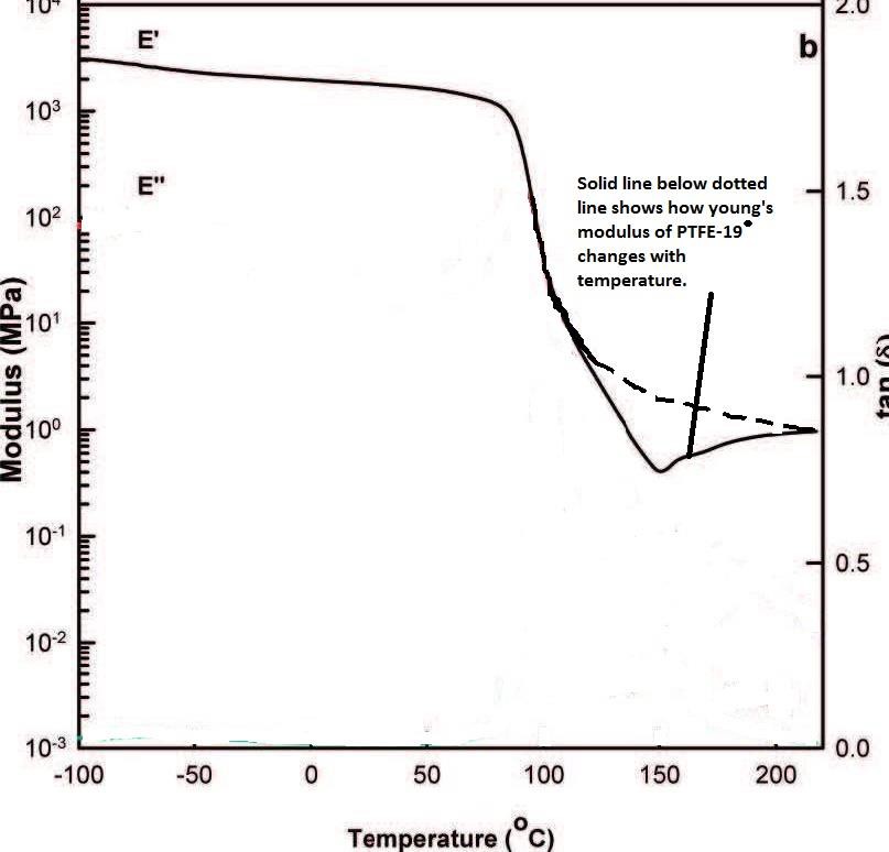 °
Figure 9: Young’s modulus versus temperature graph of PTFE at -19° C [18-20].
In most SMPs proper mechanism design is a common approach to achieve cyclic actuation[18-20]. One of the polymers that have been reported to show cyclic actuation is PTFE at 19 degree Celsius by the means of reversible phase transformation[21].
°
Figure 9: Young’s modulus versus temperature graph of PTFE at -19° C [18-20].
In most SMPs proper mechanism design is a common approach to achieve cyclic actuation[18-20]. One of the polymers that have been reported to show cyclic actuation is PTFE at 19 degree Celsius by the means of reversible phase transformation[21].
3.7 Multi – Functional SMPs
One of the major research areas where SMPs (specifically polyurethane) have an edge over any other shape memory material is multi-function capability. In SMPs, multiple actions can be triggered in response to one or more stimuli when a prescribed or set procedure is followed[13]. The edge that SMPS have over other materials is that they are more flexible and versatile and have integrated functions of sensing and actuation down to the sub-micron level which is an important parameter for wide range of biomedical applications[23,24]. Numerous investigations have been carried out to show that SMPs of random size can operate as intelligent machines[25].3.8 Triple Shape memory effects
In comparison to typical double SMPs which have one permanent shape and one temporary shape, triple Shape memory polymers have one permanent shape and two temporary shapes[26]. Triple shape memory polymers have two switching temperature, the triple SMP transitions from 1st temporary shape to the 2nd temporary shape at first Tsw and then from 2nd temporary shape to permanent shape at second Tsw as shown in figure(10). To achieve this, many different strategies have been fabricated for preparation of triple SMPs. The chemical methods include graft or block copolymerization [40,41- 43]and chemical cross-linking coupled with supramolecular bonding[29].
Figure 10. Storage modulus vs Temperature of a Triple SMP[147].
The physical methods include physical cross-linking of various crystalline polymers and bilayer structure of two double SMPs which have significant difference in their switching temperatures[44-46]. The most common technique used in past decades to make triple SMPS was mixing existing polymers with each other but only few polymer couples are completely or partially miscible. The two widely practiced techniques for mixing immiscible double SMPs are sea-island architecture and cocontinuous architecture. In polymer blends with sea-island architecture, one polymer (island) is dispersed in the continuous matrix of the second polymer (sea). Due to more number of particles of the continuous polymer (sea), its material properties are dominant in the blend. On the other hand cocontinous architecture has a significant advantage, in this each component forms a three-dimensionally per- locating network i.e. both components can be taken as continuous matrix and hence specifically good properties of both SMPs can be synergically combined[53-56]. Cocontinuous architecture has led to development of some novel materials enhanced electrical, mechanical, optical and transporting properties[47-50]. For example polyethylene/polypropylene blends are chemically cross-linked to give triple SMPs[51].
3.9 Advantages of Shape Memory Polymers
Although shape memory alloys (SMAs) are better choice when it comes to applications that deal with high forces and stresses but with accelerating development and wide investigation of SMPs, their features are becoming more and more prominent, specifically when compared with SMAs[12]. (1) SMPs can use diverse external stimuli and triggers to activate shape recovery: In addition to heating, light, magnetic field, chemical reaction and electricity are also capable of triggering shape recovery and can co-exists leading to multi-sensitive materials. (2) Their programming can be done with different stimuli and multi-step response making them highly flexible in terms of programming.(3) Many approaches are available for designing the net points and switches for different types of SMPs.(4) Various polymers and foreign materials can be mixed to give desired Shape memory effect.(5) The properties of an SMP can be easily tuned/engineered by controlling the composition and synthesis method.(6) One major advantage of SMP, as they are soft and more bio-compatible as compared to SMA, is that they can be biodegradable and are more well-suited to respond to human senses, tissues and body temperature.(6) They can be made very light and can occupy a large volume (foam) which is very important feature, particularly when considering Aerospace applications but further investigation is necessary before using it in Space as this application demands a steady and well controlled shape memory effect to prevent damage to the space components due to vibrations that cause Noise and unnecessary heating of space- craft components [17].3.10 Constitutive model for shape memory polymer behavior
3.10.1 Thermo-mechanical Constitutive Model
As documented previously, Shape memory effect in an SMP comprises of two concurrent processes: (1) the transition from rubbery behavior at high temperatures to glassy behavior at low temperatures and (2) the storage of deformation, incurred at temperatures above glass transition temperature, during cooling. The rubbery behavior in the first process is dominated by entropic energy whereas the glassy behavior is dominated by internal energy energy[66]. This transition of energy between rubbery and glassy phase is given by the Helmholtz energy equation[65]: (3)
Here Htotal is the total Helmholtz energy at a certain temperature T; Hr is the Helmholtz energy of the material in rubbery phase at T>Tg ; Hg is the Helmholtz energy of the material in glassy phase at T<Tg; fr and fg are volume fractions of rubbery and glassy phase and are functions of temperature.
In the 2nd process, the deformation storage or SMP's resistance to inelastic deformation below glass transition temperature arises due to the intermolecular resistance to segmental rotation and the entropic resistance to the molecular alignment. It is believed that the glassy phase formed during cooling may have different deformation history and hence is further divided into two phases: initial glassy phase (IGP) and frozen glassy phase (FGP). IGP refers to the glassy phase in initial configuration of the material and is deformed initially (at the beginning of an analysis) under application of external load. FGP on the other hand refers to the newly formed glassy phase caused by decrease in temperature [66].
Therefore, the Helmhotz energy equation can be revised and written as:
(4)
Here fg0 represents volume fraction of IGP and fg1 represents volume fraction of FGP. At any point . In our case, since the pre-deformation step is performed at T> Tg, fg0 is almost 0 initially. Both IGP and FGP volume fraction increase as the temperature is cooled down below Tg [66].
3.10.2 Deformation and stresses
The material response over Tg shows rubber like hyper-elastic behavior. To capture this behavior the method by Boyce and co-worker can be used which decomposes the stress response into two components : equilibrium time dependent component representing viscoplastic behavior and equilibrium time independent behavior for rubber like behavior[67,68]. This one dimensional analog of a viscoplastic model of glassy polymer is shown in figure 11.
Figure 11. A One Dimensional representation of visco-plastic model of a SMP[146].
3.11 Conclusion on Literature review
The literature review summarizes the types, mechanisms and structure of SMPs and some of the basic concepts and parameters governing the shape memory effect in polymers. SMPs can be classified by the means of polymerization methods, nature of their net points, shape memory functionality and external stimuli. The main focus of this literature review was on thermo-sensitive shape memory polymers. The superiority of SMPs to SMAs due to various SMP properties have also been stated in this literature review. Some insight has also been put in different types of shape memory effect and how various factors influence the stability of SME.
A thermo-mechanical constitutive model explaining the shape memory effect has also been included in this Literature review. Some information about new concepts like Micro-stereo lithography, multi-functionality polymers and triple shape memory effect has been presented in this review.- AIMS AND OBJECTIVES
- Aim
- OBJECTIVES
- Looking at mechanical properties of different shape memory polymers and see the ones that can be printed with a Delta 3d printer and are readily available.
- Testing PLA and TPU to see how they behave under different constrain/free range conditions
- Would be doing cyclic thermomechanical tension tests on PLA and TPU to see how many cycles it takes for shape memory effects to wear off in different polymers.
- Obtain a set of experimental data of shape memory and material properties such as shape
- Would be looking into applications of 4D printing in Healthcare sector particularly and see if any of the shape memory polymers can fulfil the needs for those applications. [150]
- EXPERIMENTAL METHODOLOGY
- MATERIALS
- TEST PIECE PREPARATION
Figure 12: Dog bone shape specimen with dimensions according to ASTM standards.
Both PLA and TPU test piece were 3d printed in dog bone shape as shown in figure 12. PLA was 3D printed at 210 degress nozzle temperature, 50mm/s printing speed from nozzle of 0.4mm diameter and printer bed at 80 degree celcius using Delta 3d printer (fig13.) and UP 3d printer (fig14.) whereas TPU because of being a flexible 3d filament could not be printed on both 3d printers mentioned above as they don’t have the proper gear system installed for flexible material.
Figure 13: UP 3D printer[174]. Figure 14: Delta 3D [175].
Figure 15: Raise3D N2 3D printer [176].
Hence, TPU was printed on Raise3D N2 (fig15.) at 230 degree Celsius nozzle temperature, 50mm/s print speed from nozzle of 0.4mm diameter and printer bed at 60 degree Celsius. which is more advanced 3d printer and is capable of 3D printing both flexible and rigid filament. Both test pieces had identical dimensions which were according to the ASTM standards for tensile testing of plastics (D638) [85].
- APPARATUS USED
Figure 16: A hand driven Hounsfield Tensometer.
A full view of the Hounsfield tensometer is shown in the figure below with movement controls on the right of the picture and specimen mounting points and measuring head on the left of the picture. The grippers as shown in the figure 16 were used to clamp the test specimens in a wooden box. The measurement head of the hounsfield tensile tester consists of a recording drum, a cursor, mercury column, a load force scale and spring beam which is hidden behind the mercury column [89]. Spring beams were picked carefully, the maximum force that a spring beam can withstand should be greater than the breaking load/force of the test specimen, and were used to support the load applied to the test specimen. When the beam is subjected to tensile load, the mercury column rises to display the applied force. Recording drum and the cursor were used to plot the stress-strain data on a graph paper. A mercury thermometer was used to keep check on the specimen temperature. A ruler was used to measure the length of the specimen at different stages during the test.
Figure 17: Dry Ice was mixed in the methanol drum to bring it to the desired temperature.
A metal drum containing methanol and dry ice as shown in figure 17 was used when temperatures below -24 ° were needed in the polyurethane tests. Methanol was brought to desired temperature by carefully adding dry ice in the cryogenic vacuum drum. A special thermo-meter is used to measure the temperatures below 0 degree Celsius.
- EXPERIMENTAL PROCEDURE
- PLA test procedure
- The first step involves heating the test piece above its glass transition temperature by the means of pouring hot water (around 85 degree Celsius) in the wooden box containing the specimen, and stretching the specimen to the prescribed strain. It is important to monitor the temperature so that it does not go above crystallization temperature or below Tg of the polymer during this step.
- In next step the test piece is cooled down to a temperature at least 20 ° below its glass transition temperature (40 °) under constant strain Ep. This step fixes the temporary shape of the specimen.
- Clamps are then driven back until zero stress condition is obtained which causes the sample to buckle by a very small amount.
- After this the experiment is conducted in two ways depending on whether we are performing a constrained recovery or free recovery:
- For Constrained recovery, the sample is reheated above its Tg while still under constant strain in which case we see recovery stress developed.
- For free recovery, the sample is reheated above its Tg without any constraints in which case the sample contracts and recovers it's permanent shape.
- TPU test procedure
- For TPU, The test piece is stretched to the prescribed strain at room temperature 20 ° as the Tg of TPU is -24 degree.
- The next step involves cooling down the test specimen below -24 degree. To achieve this Dry Ice is added to the methanol, which is stored in a cryogenic vacuum drum, until it reaches a temperature at least 10 ° below Tg of TPU and this solution is poured in the wooden box where the test piece is clamped. This fixes the temporary shape of TPU specimen.
- The clamps are brought back until zero force is shown on the mercury scale.
- Next, the loading constraints are released and methanol is pumped out which brings the specimen above its Tg for it to exhibit SME.
- Alternatively, the sample is kept under constrain while methanol is pumped out in which case we see recovery stress developed when the specimen exhibits SME.
Figure 18
Figure 19
Figure 18. Shows a typical stress-strain temperature curve obtained from a thermo-mechanical tensile test[140].
Figure 19. shows a typical stress- strain curve obtained from a thermo-mechanical tensile test[141,107].
A graphical illustration of the experiment mentioned above in terms of stress-strain- temperature data is shown in the figure (11). Key values that were noted at the end of each cycle for both PLA and TPU were maximum stress value (symbol) at the end of the programming step, stress developed due to thermal contraction when the test specimen is
cooled below Tg and the recovery stress that was generated on reheating the samples above Tg in Constrained analysis.
Both PLA and TPU specimens tests were performed at 3 different values of prescribed strain 10%,25% and 50%. Low values of strain were chosen because the PLA specimen of 4mm thickness would break in the first cycle if the strain exceeds 50%.For test pieces of both SMPs and for both constrained and free recovery, 4 cycles were performed at each strain unless they failed before 4 cycles. The test matrix was prepared for PLA and TPU as shown in Table 1 and Table 2 below.
Some tests, using the similar procedure described above, were also carried out to see how well the TPU and PLA specimen undergo compression test at 50 % strain. The results of these tests are shown in section 6.1.
Table 1: PLA test matrix.
| Prescribed Strain | |||
| Constrained Recovery | 10% | 25% | 50% |
| Cycle 1 | ✓ | ✓ | ✓ |
| Cycle2 | ✓ | ✓ | |
| Cycle 3 | ✓ | | |
| Cycle 4 | ✓ | | |
| Free Recovery | |||
| Cycle 1 | ✓ | ✓ | ✓ |
| Cycle2 | ✓ | ✓ | |
| Cycle 3 | ✓ | | |
| Cycle 4 | ✓ | | |
| Prescribed Strain | |||
| Constrained Recovery | 10% | 25% | 50% |
| Cycle 1 | ✓ | ✓ | ✓ |
| Cycle2 | ✓ | ✓ | ✓ |
| Cycle 3 | ✓ | ✓ | ✓ |
| Cycle 4 | ✓ | ✓ | ✓ |
| Free Recovery | |||
| Cycle 1 | ✓ | ✓ | ✓ |
| Cycle2 | ✓ | ✓ | ✓ |
| Cycle 3 | ✓ | ✓ | ✓ |
| Cycle 4 | ✓ | ✓ | ✓ |
6. RESULT AND DISCUSSION
6.1 RESULT
As it can be seen in the figure 20 and 21 below the permanent deformation occurred in PLA test specimens and it failed the compression tests whereas the TPU test specimen showed almost complete recovery after both were compressed to half of their lengths respectively.
- (b)
(a) (b)
(c) (d)
Figure 21: Illustrates the SME in TPU specimens after being compressed to half its length.
Two types of cyclic thermo-mechanical tests namely free and Constrained recovery tests were performed on test specimens of PLA and TPU. At each strain value 4 cycles were performed, unless the test specimen failed before 4 cycles, to study the cyclic behavior of 3d printed structures of PLA and TPU. Figure 23 and figure 27 shows stress-strain-temperature graphs, comprising of paths 1-2-3-4-5a, constrained recovery test at 25% strain for PLA and TPU respectively. Similar graphs for all 4 cycles at strain:10%, 25% and 50% for PLA and TPU are presented in Appendix-A.
Figure 25 and 29 shows stress strain temperature graphs, comprising of paths 1-2-3-4-5b, free recovery test at 25% strain for PLA and TPU respectively. Similar graphs for all 4 cycles at strain:10%, 25%, 50% for PLA and TPU are presented in Appendix-B. Figure 24 and 26 presents the stress-strain data of 4 cycles in 2-D graphs for free and constrained recovery tests conducted at 10% strain on PLA samples, and, Figure 26 and 30 present the stress-strain data of 4 cycles in 2-D graphs for free and Constrained recovery tests conducted at 10% strain on TPU samples. Rest of 2-D graphs are presented in Appendix-A and Appendix-B for Constrained and Free recovery tests respectively.
From these graphs critical stress values, εu (applied strain) and εp (stored strain) were easily read (shown in figure 22) and used to determine shape fixity and shape recovery ratios of PLA and TPU samples for both free and constrained recovery tests. The slope of the loading curve and unloading curve, as shown in figure 22, was used to calculate the high temperature Young’s modulus and Low temperature Young’s modulus respectively for both PLA and TPU test specimens.
Table 3,10 shows critical stress values obtained from Constrained and free recovery tests, respectively, on PLA samples and Table 6,13 shows critical stress values obtained from Constrained and free recovery tests, respectively, on TPU samples. Tables 4, 7, 11 and 14 show the high temperature and low temperature Young’s modulus obtained from different constrain and free recovery tests on PLA and TPU test samples. Tables 5,8,12,15 and Tables 9,16 present the shape fixity and shape recovery data respectively for PLA and TPU test samples under Constrain and free test conditions.
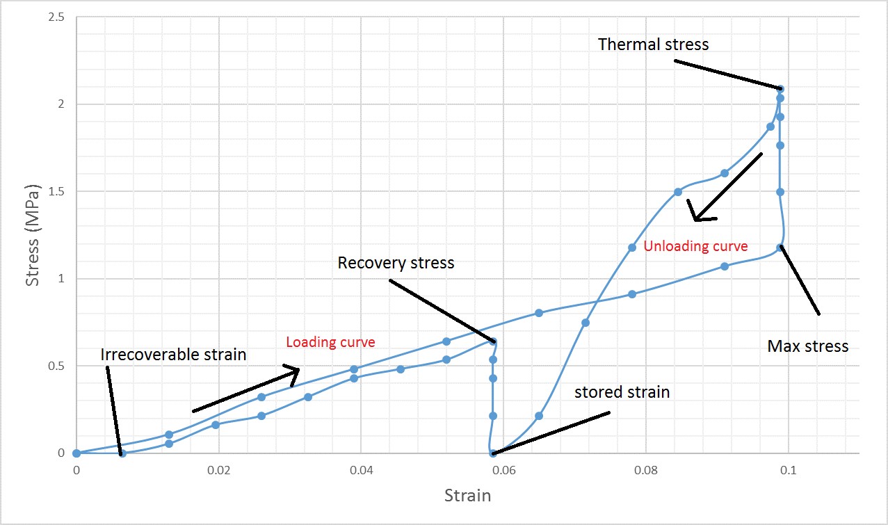 Figure 22: critical values in 2-D stress strain graph.
Figure 22: critical values in 2-D stress strain graph.
- PLA thermo-mechanical tensile test results
- Constrained recovery tests
Figure 23: Stress-strain temperature graph of Constrained recovery test at 25% strain, cycle 1, for PLA.
1-deforming the specimen at 80 degrees (programming), 2- cooling the specimen down to 40 degrees to fix the temporary shape, 3- bringing the specimen to zero stress condition, 4- reheating the specimen to trigger the SME and 5a- bringing the test piece back to zero stress from recovery stress which is developed on reheating.
Figure 24: 2-D stress-strain graph of all cycles for PLA at 10% strain constrained recovery test.
| Cycles | Prescribed Strain | ||||||||
| 10% | 25% | 50% | |||||||
| σmax | σthermal | σrecovery | σmax | σthermal | σrecovery | σmax | σthermal | σrecovery | |
| Cycle 1 | 1.76 | 2.94 | 0.64 | 2.46 | 3.59 | 1.33 | 4.39 | 4.45 | 2.05 |
| Cycle 2 | 2.89 | 4.06 | 1.09 | 3.85 | 4.7 | 2.12 | - | - | - |
| Cycle 3 | 2.4 | 3.58 | 1.005 | - | - | - | - | - | - |
| Cycle 4 | 2.48 | 3.69 | 0.909 | - | - | - | - | - | - |
bgm
2017-04-24 08:25:49
--------------------------------------------
22.1 to be consistent
bgm
2017-04-24 08:26:39
--------------------------------------------
0.21, 0.46 to be consistent
| Cycles | Prescribed Strain | |||||
| 10% | 25% | 50% | ||||
| Erubbery | Eglassy | Erubbery | Eglassy | Erubbery | Eglassy | |
| Cycle 1 | 22.07 | 92.7 | 11.5 | 93.2 | 8.8 | 104.2 |
| Cycle 2 | 42.8 | 110.6 | 17.5 | 114.6 | - | - |
| Cycle 3 | 35.6 | 102.3 | - | - | - | - |
| Cycle 4 | 29.6 | 96.5 | - | - | - | - |
| Mean | 32.5 | 100.4 | 14.5 | 103.6 | 8.8 | 104.2 |
| Cycles | Prescribed Strain | |||||
| 10% | 25% | 50% | ||||
| εu | Shapefixity ratio | εu | Shapefixity ratio | εu | Shapefixity ratio | |
| Cycle 1 | 0.068 | 68% | 0.210 | 84.5% | 0.460 | 92% |
| Cycle 2 | 0.064 | 64% | 0.210 | 83.6% | - | - |
| Cycle 3 | 0.065 | 65% | - | - | - | - |
| Cycle 4 | 0.061 | 61% | - | - | - | - |
| Mean | 64.5% | 84.1% | 92% | |||
- Free Recovery tests
Figure 25: Stress-strain temperature graph of free recovery test at 25% strain, cycle 1, for PLA.
1-deforming the specimen at 80 degrees (programming), 2- cooling the specimen down to 40 degrees to fix the temporary shape, 3- bringing the specimen to zero stress condition, 4- reheating the specimen to trigger the SME and 5b- the test piece is allowed to recover freely after removing the constrains.
bgm
2017-04-24 08:28:42
--------------------------------------------
Here you are using 3 significant figures. Try to be consistent.
Figure 26: 2-D stress-strain graph of all cycles for PLA at 10% strain free recovery test.
| Cycles | Prescribed Strain | |||||
| 10% | 25% | 50% | ||||
| σmax | σthermal | σmax | σthermal | σmax | σthermal | |
| Cycle 1 | 2.14 | 3.32 | 2.38 | 3.47 | 4.07 | 4.92 |
| Cycle 2 | 2.46 | 3.85 | 3.63 | 4.65 | - | - |
| Cycle 3 | 2.78 | 3.95 | - | - | - | - |
| Cycle 4 | 3.31 | 4.38 | - | - | - | - |
bgm
2017-04-24 08:29:23
--------------------------------------------
Here a mixture of 3, 4 and 5 significant figures
| Cycles | Prescribed Strain | |||||
| 10% | 25% | 50% | ||||
| Erubbery | Eglassy | Erubbery | Eglassy | Erubbery | Eglassy | |
| Cycle 1 | 25.55 | 94.77 | 10.2 | 102.9 | 8.40 | 115.76 |
| Cycle 2 | 29.37 | 104.9 | 14.52 | 102.76 | - | - |
| Cycle 3 | 33.19 | 112.85 | - | - | - | - |
| Cycle 4 | 33.1 | 101.38 | - | - | - | - |
| Mean | 30.3 | 103.48 | 12.36 | 102.84 | 8.40 | 115.76 |
| Cycles | Prescribed Strain | |||||
| 10% | 25% | 50% | ||||
| εu | Shapefixityratio | εu | Shapefixityratio | εu | Shapefixityratio | |
| Cycle 1 | 0.065 | 65% | 0.216 | 86.4% | 0.460 | 92% |
| Cycle 2 | 0.063 | 63% | 0.204 | 81.6% | - | - |
| Cycle 3 | 0.063 | 63.3% | - | - | - | - |
| Cycle 4 | 0.059 | 58.8% | - | - | - | - |
| Mean | 62.45% | 84% | 92% | |||
| Cycles | Prescribed Strain | |||||
| 10% | 25% | 50% | ||||
| Shape recovery(constrained) | Shape recovery(free) | Shape recovery(constrained) | Shape recovery(free) | Shape recovery(constrained) | Shape recovery(free) | |
| Cycle 1 | 87.5% | 87.5% | 59.8% | 76% | 39% | 67.5% |
| Cycle 2 | 85.9% | 85% | 56.4% | 72% | - | - |
| Cycle 3 | 84.2% | 85% | - | - | - | - |
| Cycle 4 | 84.25% | 75% | - | - | - | - |
| Mean | 85.46 | 83.12 | 58.1 | 74 | 39 | 67.5 |
- TPU thermo-mechanical tensile test results
- Constrained recovery tests
Figure 27: Stress-strain temperature graph of Constrained recovery test at 25% strain, cycle 1, for TPU.
1-deforming the specimen at 15 degrees (programming), 2- cooling the specimen down to -40 degrees to fix the temporary shape, 3- bringing the specimen to zero stress condition, 4- reheating the specimen to trigger the SME and 5a- bringing the test piece back to zero stress from recovery stress which is developed on reheating.
Figure 28: 2-D stress-strain graph of all cycles for TPU at 10% strain constrained recovery test.
| Cycles | Prescribed Strain | ||||||||
| 10% | 25% | 50% | |||||||
| σmax | σthermal | σrecovery | σmax | σthermal | σrecovery | σmax | σthermal | σrecovery | |
| Cycle 1 | 1.18 | 2.08 | 0.64 | 1.55 | 2.3 | 0.43 | 2.99 | 3.58 | 1.60 |
| Cycle 2 | 1.39 | 2.03 | 0.53 | 1.55 | 2.08 | 0.75 | 3.31 | 3.64 | 1.82 |
| Cycle 3 | 1.17 | 1.71 | 0.64 | 2.08 | 2.67 | 1.12 | 2.89 | 3.62 | 1.71 |
| Cycle 4 | 1.33 | 1.71 | 0.85 | 1.6 | 2.4 | 1.25 | 4.9 | 5.13 | 2.67 |
bgm
2017-04-24 08:30:04
--------------------------------------------
MPa
| Cycles | Prescribed Strain | |||||
| 10% | 25% | 50% | ||||
| Erubbery | Eglassy | Erubbery | Eglassy | Erubbery | Eglassy | |
| Cycle 1 | 11.77 | 50.27 | 6.92 | 54.76 | 6.3 | 54.4 |
| Cycle 2 | 13.9 | 42.29 | 7.35 | 37.81 | 6.79 | 51.23 |
| Cycle 3 | 11.7 | 33.79 | 9.28 | 48.63 | 6.09 | 70.64 |
| Cycle 4 | 13.3 | 41.2 | 6.75 | 49.48 | 10.33 | 52.61 |
| Mean | 12.65 | 41.87 | 7.57 | 47.67 | 7.38 | 57.22 |
Table 11: Young’s modulus (in Mpa) at rubbery and glassy state for constrained recovery tests of TPU
| Cycles | Prescribed Strain | |||||
| 10% | 25% | 50% | ||||
| εu | Shapefixityratio | εu | Shapefixityratio | εu | Shapefixityratio | |
| Cycle 1 | 0.058 | 58% | 0.208 | 83.2% | 0.434 | 88.84% |
| Cycle 2 | 0.052 | 52% | 0.195 | 78% | 0.433 | 86.64% |
| Cycle 3 | 0.049 | 49% | 0.196 | 78.4% | 0.441 | 88.2% |
| Cycle 4 | 0.058 | 58% | 0.200 | 80% | 0.410 | 81.9% |
| Mean | 54.12 | 80 | 86.4 | |||
- Free Recovery tests
Figure 29: Stress-strain temperature graph of free recovery test at 25% strain, cycle 1, for TPU.
1-deforming the specimen at 15 degrees (programming), 2- cooling the specimen down to -40 degrees to fix the temporary shape, 3- bringing the specimen to zero stress condition, 4- reheating the specimen to trigger the SME and 5b- the test piece is allowed to recover freely after removing the constrains.
bgm
2017-04-24 08:30:31
--------------------------------------------
MPa
Figure 30: 2-D stress-strain graph of all cycles for TPU at 10% strain free recovery test.
| Cycles | Prescribed Strain | |||||
| 10% | 25% | 50% | ||||
| σmax | σthermal | σmax | σthermal | σmax | σthermal | |
| Cycle 1 | 2.14 | 3.21 | 3.21 | 3.53 | 2.51 | 3.48 |
| Cycle 2 | 1.71 | 2.57 | 2.67 | 3.53 | 2.89 | 3.37 |
| Cycle 3 | 1.39 | 2.89 | 2.35 | 3.42 | 2.62 | 2.83 |
| Cycle 4 | 1.49 | 2.67 | 1.92 | 2.89 | 2.51 | 3.1 |
Table 13: Critical stresses (in Mpa) for free recovery tests of TPU.
bgm
2017-04-24 08:30:45
--------------------------------------------
MPa
| Cycles | Prescribed Strain | |||||
| 10% | 25% | 50% | ||||
| Erubbery | Eglassy | Erubbery | Eglassy | Erubbery | Eglassy | |
| Cycle 1 | 21.4 | 66.88 | 13.54 | 74.78 | 5.16 | 67.51 |
| Cycle 2 | 17.1 | 47.11 | 10.68 | 47.38 | 5.78 | 52.24 |
| Cycle 3 | 13.9 | 57.1 | 9.91 | 70.51 | 5.24 | 39.85 |
| Cycle 4 | 14.9 | 63.69 | 8.59 | 59.56 | 5.30 | 48.06 |
| Mean | 16.82 | 58.69 | 10.68 | 63.05 | 5.37 | 51.9 |
Table 14: Young’s modulus (in Mpa) at rubbery and glassy state for free recovery tests of TPU.
| Cycles | Prescribed Strain | |||||
| 10% | 25% | 50% | ||||
| εu | Shapefixityratio | εu | Shapefixityratio | εu | Shapefixityratio | |
| Cycle 1 | 5.46 | 54.6% | 20.28 | 81.12% | 44.85 | 89.7% |
| Cycle 2 | 4.87 | 48.7 | 17.9 | 71.6% | 43.55 | 87.1% |
| Cycle 3 | 4.94 | 49.4% | 20.4 | 81.65% | 43 | 86% |
| Cycle 4 | 5.58 | 55.8% | 20.19 | 80.76% | 42.9 | 85.8% |
| Mean | 52.12 | 78.8 | 87.15 | |||
| Cycles | Prescribed Strain | |||||
| 10% | 25% | 50% | ||||
| Shape recovery(constrained) | Shape recovery(free) | Shape recovery(constrained) | Shape recovery(free) | Shape recovery(constrained) | Shape recovery(free) | |
| Cycle 1 | 95.5% | 100% | 40.8% | 92% | 42% | 92% |
| Cycle 2 | 95.5% | 100% | 72% | 84% | 64% | 92% |
| Cycle 3 | 96.5% | 100% | 80.8% | 84% | 70.4% | 88% |
| Cycle 4 | 96.5% | 100% | 86.8% | 92% | 88% | 88% |
| Mean | 96% | 100% | 70.15% | 88% | 66.1% | 90% |
6.2 DISCUSSION
The stress strain graph is fairly linear, when the sample is stretched at temperature above Tg, apart from the initial slow start in some of the tests due to minor calibration errors which were taken into account while calculating results. We see recovery stress develop in both TPU and PLA samples when they are heated above Tg because the micro-Brownian motion of a soft segments in SMP gets active at temperatures above Tg and is frozen at temperature below Tg. The modulus at lower temperature is much higher in all cases and hence strain is recovered elastically with a steep slope during the unloading process. The increase in stress when the test specimen is cooled below Tg can be seen in the figure 16 and is due to thermal contraction. The recovery temperature in the tests was Kept at least 10 degrees more than the Tg of both PLA and TPU tests because as the cycles increase more crystallization takes place and higher thermal energy is required for strain recovery [153]. For TPU max stress decreases sharply in first cycle and decreases gradually after the second cycle. This is because softening of TPU test specimens takes place due to high visco-elastic nature of TPU [22].On the
other hand the max stress increases with increasing number of cycles for PLA. One possible reason for this is that due to less visco-elastic nature of PLA than TPU, it undergoes permanent deformation i.e. straightening of the tangled molecular chains in PLA as the loading cycles increase. Therefore, more actual molecules of PLA are stretched as the number of cycles are increased resulting in increase in max stress.
The strain at the end of the unloading step is a little less than the applied strain at 25% and 50% strain thermo-mechanical tests of PLA and TPU and does not change much with cycles which means that excellent shape fixity can be achieved at these strains.
A increase in recovery stress was observed with increasing number of cycles at 10%, 25%, 50%strain in Constrained thermo-mechanical tensile tests for TPU and PLA because as the number of cycles increase more hardening due to orientation of molecular chains and crystallization takes place. Also in polyurethanes, the glass transition temperature decreases when immersed in water. The water can be separated in two parts free water and bound water. Free water has no effect on glass transition temperature whereas bound water significantly decreases the glass transition temperature by weakening the Hydrogen bonding between N-H and Cao groups in polyurethane [6].
Although the experimental value Young’s Modulus for both PLA and TPU test specimens was less than theoretical value (which might be due to less dense/fine cross-section of the 3D printed test specimens as comparted to solid PLA and TPU films) but the value of Young’s modulus did not vary much at a given strain and was similar in both free and constrained recovery tests as shown in table (2.5,9 and 12). In test specimens of both SMPs, the average glassy state Young’s modulus remains almost the same in constrained and free recovery tests but the rubbery state Young’s modulus decreases with increase in prescribed strain due to decoupling of polymer chains with imperfect crystalline parts that takes place at temperatures above Tg [160].
Higher recovery stress and peak stress was seen in PLA as compared to TPU in all tests which was expected as PLA has higher elastic modulus than TPU in both rubbery and glassy state and is more brittle in nature as the soft segment percentage in it much less than the hard segment.
PLA failed after two cycles at 25 % strain and after one at 50% strain in both free recovery and Constrained recovery tests whereas TPU underwent complete recovery in all thermo-mechanical cycles at 25 and 50 percent strain. The reason for this because the stability of shape memory effect is governed by the damage to permanent phase. Repeated thermo-mechanical shape memory tensile cycles cause more damage to the chain entanglements and π-π interactions (act as the permanent phase) of PLA than polyurethane because of less number of physical cross-links and less strong elastic behavior of PLA [152,155].
The stress-strain slope in the first cycle of PLA samples tested at 50% strain, in both free and constrained recovery, stopped increasing towards the end which might be because some minor cracks would have developed as it was stretched due to brittle nature of PLA and due to gradual cooling of water during the experiment.
6.2.1 In terms of Shape fixity and Shape recovery ratio
The shape recovery ratio of PLA samples followed a decreasing trend as the number of cycles and prescribed strain increased but stabilized after 3 cycles. This happened because repetitive loading distorts the polymer chains and triggers viscous flow. The reorientation/ straightening of polymeric chains is limited by the physical cross-links in PLA. Thus, after a sufficient number of cycles reorientation /straightening of polymeric chains occurs and viscous flow stabilizes [157]. (Lui et.al.2007) reported that breakdown of some elastic segments in SMP is also a cause for cyclic degradation for some SMPs [158]. Also for PLA as the breaking strain was almost 55% in rubbery state , Hardening of SMP above maximum strain results in increase in Young’s modulus and decrease in recovery ratio. In TPU the recovery ratio increased with cycles for constrained tests and remained almost same for free recovery tests. This possibly happened due to lowering of Tg of TPU when it is immersed in water for long enough time (as discussed above) and also numerous studies have shown that Polyurethanes show moisture induced SME [6]. However, TPU samples followed similar trend to PLA of decreasing recovery ratio as the prescribed strain increased. Both PLA and TPU showed better shape recovery ratios in free recovery tests than constrained recovery tests with TPU showing shape recovery ratio between 85-100% for free recovery tests at all strains. The shape fixity ratio increased as the prescribed strain increased which was expected because the more the SMP is stretched more untangling of the long polymeric molecular chains, which are initially twisted and tangled, takes place in it which in return reduces the amount of strain required to bring the test specimen back to condition where it exerts zero force/stress. For the same reason higher prescribed strain reduce the shape recovering capability of an SMP. Hence, care should be taken while selecting a value for prescribed strain for an application. In both PLA and TPU tests the shape fixity ratio decreased minutely as the number of cycles increased which might be due to lowering of Tg of PLA and TPU caused by accumulation of bound water in molecular chains of mentioned SMPs. In general, PLA showed better shape fixity than TPU whereas TPU showed better shape recovery than PLA , as shown in the results above, because there is bigger difference in Young’s modulus of rubbery and glassy state for PLA than TPU as shown in tables (2,9 and 5, 12) [155]. The low modulus favors the deformation in glassy state and high modulus favors the fixing of temporary shape at low temperature. Another reason for better shape recovery ratio in TPU is that both programming and recovery temperature of for TPU was at least 30 degrees more than it's Tg whereas it was only 10 degrees more than Tg in PLA tests due limitations of the apparatus used and numerous researches have shown that micro-Brownian motion of molecules in SMP becomes increasingly active at higher temperatures as long as the temperature is kept below the crystallization temperature of the SMP [153,22].7. Applications
There is a plethora of potential applications for SMPs in the field of smart clothing, space, medical and structural applications, reconfigurable tools [162], self-healing and health monitoring, biomedical devices, heat shrinkable tubes, intelligent packing and bio-sensors (141).7.1 Medical Applications
As per recent reports almost 70% of the SMP patents are related to medical applications [162]. Commercial sources such as New Ortho Polymers, MnemoScience and Medshape have provided solutions for minimal invasive surgery.
Figure 31: (a) shape memory polymer adapter design with tubular adapter deployed.(b) flow visualization without SMP adapter and flow visualization with SMP adapter (c). ID, OD and AV means inner diameter, outer diameter and arteriovenous respectively [168].
An ingenious dialysis needle adapter with a fixed SMP tube was developed by Ortega et. Al. [168]. This adapter is threaded through the dialysis needle and thermally expanded via blood contact to reach an equilibrium as shown in figure 31. Following dialysis, the SMP adapter is retracted back through the dialysis needle.
An interesting application involving magnetite filled-SMP was developed by schimdt [167] for tumor therapy. The SMP is inserted via minimally invasive surgery near the tumor. Following this, localized treatment is carried out, thus preventing unwanted heating of the surrounding healthy tissues as
opposed to current therapies.
Small et al. [166] developed a prototype the uses the combination of SMP stent and SMP foam for treatment of endovascular embolization of non-necked fusiform aneurysms. Stent was used to maintain the lumen open in parent artery while the foam activated the embolization of the aneurysms. SME in an IR-dye-doped commercial SMPU was triggered by photo thermal actuation via laser irradiation.
Baer and coworkers used photo-thermal effect to trigger the SME of a vascular SMP stent. They developed and studied a prototype vascular stent and deploying mechanism that used a Tg-based thermo-plastic SMPU, Diaplex MM520, incapacitated with a light- absorbing Pt-based dye. In the stress free state, the stunt was of an expanded diameter, and this stent was crimped with SM fixing on a fiber optic and combined light diffusion/SMP foam. Experiments to study the light activated deployment of the crimped state towards the expanded diameter state were carried out in a silicone rubber tube with and without blood as a stimulant. The expansion was quite effective and could possibly be used as an alternative for balloon-aided expansion but only at high power and without convective cooling [169].
7.2 Space Applications
SMPs are being increasingly considered for space applications because that would provide a large reduction in cost, volume and weight of space machines. Some of the major applications that have been discussed in this sector until now include spring-lock truss elements for large booms, nano wheels for Mars rovers and solar sails that use CNT-loaded CHEM micro foams[165].7.3 Textile Applications
A research carried out by Vili [171] reviews the use of SMPs and SMAs for smart interior applications such as room partition, wall hanging and window treatment using temperature changes, electric current and sunlight as triggerers. Numerous studies have also been carried out on use of SMP for smart clothing such as development of auto-sleeve shortning shirt by Corpo Nove [171] and Sports clothing by DiAPLEX [162] made of a fabric that opens its micro-structure when subjected to increase in temperature.7.4 Structural Applications
Figure 32: epoxy based SMP (blue) reversible adhesion with pressure sensitive adhesive. (b) SMP in fixed state and SMP in curved shape (c) after thermally induced shape recovery [170].
In terms of structural applications a self-peeling reversible adhesive using an epoxy-based SMP was developed by Xie and Xao [170]. As shown in figure 32, in stress free state the SMP is chosen to be in curved shape, applying pressure above Tg results in a very high pull-off strength(60kPa) and reheating it above Tg triggered SME in SMP causing self-peeling of the adhesive. This process can by repeated multiple times and hence is a new achievement in the field of dry adhesives.
8. Future Work
Based on our research on SMP, we can say with certainty that development in this area is flourishing with high level of innovation from microscopic level to macroscopic level. Continuous improvement in understanding of the underlying mechanism is taking place. However, more research is required in constitutive modelling of SMP behavior, particularly, modelling of time-dependent and finite-strain shape memory phenomena is needed to predict the response of an SMP when subjected to various types of stimuli. Research can also be conducted on SMPs that respond to more than one stimulus and SMPs that have more than one switching points. High cycle performance SMPs are also a topic of research for various SMP applications. More understanding is needed for improving thermal and mass diffusivity in SMPs which would result in better shape recovery. There is also a need for SMPs that can provide tailorable recovery rate [161].
Figure 33. shows a typical micro-stereolithography process [163].
Another topic for research is 3D printing of materials using micro-stereolithography. In this process, UV rays are emitted by the light emitted by LEDs are spatially modulated with the patterns of corresponding 2D images and then projected onto the solution of photo-curable SMP as shown in figure 33. Once the illuminated material gets solidified to form a layer, the bed on which the fabricated structure rests is lowered by a set height (which is usually vertical height of one layer), followed by the projection of next layer on to the solution, This process is continued until the entire structure is fabricated[5]. Although recent researches have shown some promising SMPs triggered by photo-illumination, more research is required to actually use these polymers commercially in applications [77-81].
In this report, satisfactory results were obtained from Hounsfield tensometer, but it is not sensitive
enough for thinner SMP specimens as it can measure forces as low as 1 Kg only. In future Instron E-1000 can be used to conduct thermo-mechanical cyclic tests on thinner test specimens to get more precision in the results.
In terms of testing materials for SME. The Tg and mechanical properties of a test specimen can be tailored according to a particular application by blending polyurethane and PLA. Also, 3d printed porous structures of a given SMP can be used for compressive thermo-mechanical tests [172].
9. Conclusion
The main aim of this project is to discover shape memory polymers better than (PLA) in terms of thermos-sensitivity or endurance particularly as various researches have proven that PLA can be only considered as a partial SMP. Satisfactory results were obtained from thermo-mechanical cyclic tests performed on TPU and it can be concluded from the results that TPU is better SMP than PLA. Also blending PLA and TPU appropriately can give an SMP with Tg close to the human body temperature which can be used in bio-medical applications. Out of all smart materials SMPs were extensively researched in terms of structure mechanism, functionality, modelling, and application in this report as they are light weight, low cost, good electrical and thermal insulator, biodegradable, biocompatible, multifunctional capability and hence, show promise in wide range of potential applications. A lot has also been discussed about factors that ensure better SME and stability of SME such as decreased loading rate, high temperature and reduced holding time. A detailed Theoretical thermo-mechanical constitutive model has been presented to understand the response of SMP to thermal stimuli. Using the Hounsfield tensometer, cyclic thermo-mechanical tensile tests were performed on PLA and TPU test samples at 10%, 25% and 50% strain. A complete set of stress-strain and stress-strain- temperature data was obtained from these tests. Based on this data the following things can be concluded:- The stress strain graphs increased almost linearly in all tests. The glassy state Young’s modulus was similar in all tests conducted on PLA and TPU test specimens respectively, but the rubbery state Young’s modulus decreases with increase in prescribed strain due to decoupling of polymer chains with imperfect crystalline parts that takes place at temperatures above Tg.
- A rise in stress is seen when the sample is cooled below Tg after programming due to thermal contraction.
- The glass transition temperature of TPU decreased with increase of immersion time in water causing increase in recovery ratio with increased number of cycles due to moisture induced SME whereas recovery ratio decreased with cycles in PLA due to straightening of polymeric chains in it.
- PLA showed better shape fixity ratios than TPU due to bigger difference in Young’s modulus of
- Higher programming(Tp > Tg) and recovery (Tr > Tg) temperatures result in better shape recovery ratios
- More visco-elastic nature of TPU resulted in decrease in max stress as the number of cycles increased.
- Both PLA and TPU showed better shape recovery ratios in free recovery tests.
- A large difference in the Young’s modulus of rubbery and glassy state for test specimens of both
bgm
2017-04-24 08:33:07
--------------------------------------------
Make sure all your references are complete and formatted properly
REFERENCES
[1] MakeUseOf. (2017). 3D Printing Evolves to 4D: Here’s What We Know So Far. [online] Available at: http://www.makeuseof.com/tag/3d-printing-evolves-4d-heres-know-far/ [Accessed 1 Apr. 2017].
[2] From 3D to 4D printing: Shoufangyang.
[3] Ken Gall, Martin Mikulas, Naseem A. Munshi, Fred Beavers and Michael Tupper,"Carbon Fiber Reinforced Shape Memory Polymer Composites", Journal of IntelligentMaterials
and Structures, Vol 11, 877(2000)
[4] Thermal, mechanical and electroactive shapememory
properties of polyurethane (PU)/poly (lactic acid) (PLA)/CNT nanocomposites Mohan Raja1
, Sung Hun Ryu, A.M. Shanmugharaj Department of Chemical Engineering, Kyung Hee University,Yongin,Kyunggi-Do 449-701, SouthKorea
[5] Millsaps, B. (2017). Researchers Create Microstereolithography for 4D Printing, Potential for ImpactsinMedical, Solar & More. [online] 3DPrint.com | The Voice of 3D Printing / Additive Manufacturing.Availableat: https://3dprint.com/147312/microstereolithography-4d-printing/ [Accessed 21 Mar.2017].
[6] Effects of moisture on the thermomechanical properties of a polyurethane shape memory polymerB.Yang, W.M. Huang * , C. Li, L.Li
[7] Stratasys.com. (2017). 4D Printing Technology | Stratasys. [online] Availableat:http://www.stratasys.com/industries/education/research/4d-printing-project [Accessed 2 Apr.2017].
[8] Tibbits, S. and K. Cheung, Programmable materials for architectural assemblyand automation. Assembly Automation, 2012. 32(3): p.216-225
[9] Sun, L. and W.M. Huang, Thermo/moisture responsive shape-memory polymerfor possible surgery/operation inside living cells in future. Materials & Design, 2010.31(5): p.2684-2689
[10] Ge, Q. et al. Multimaterial 4D Printing with Tailorable Shape Memory Polymers. Sci. Rep. 6,31110;doi: 10.1038/srep31110(2016)
[11] J. Zhao, M. Chen, X. Wang, X. Zhao, Z. Wang, Z. Dang, L. Ma, G. Hu and F. Chen, "TripleShapeMemory Effects of Cross-Linked Polyethylene/Polypropylene Blends with Cocontinuous Architecture",ACSApplied Materials & Interfaces, vol. 5, no. 12, pp. 5550-5556,2013.
[12] Shape Memory Polymers Literature Review John A.Hiltz.
[13] Google Books. (2017). Polyurethane Shape Memory Polymers. [online] Availableat:https://books.google.co.in/books?id=cGXRBQAAQBAJ&lpg=PA344&dq=what%20happens%20at%20micro-structural%20level%20in%20SMP&pg=PA345#v=onepage&q&f=true [Accessed 24 Mar.2017].
[14] S J Tey et al 2001 Smart Mater. Struct. 10321
[15] T. Pretsch, "Review on the Functional Determinants and Durability of Shape MemoryPolymers",2017.
[16] H Tobushi et al 2004 Smart Mater. Struct. 13881
[17] J. Hu, Y. Zhu, H. Huang and J. Lu, "Recent advances in shape–memory polymers:Structure,
mechanism, functionality, modeling and applications", Progress in Polymer Science, vol. 37, no. 12,pp.1720-1763,2012.
[18] Haiyan Du and JunhuaZhangSoft Matter, 2010,6,3370-3376
[19] Mather, P., Luo, X. and Rousseau, I. (2009). Shape Memory Polymer Research. Annual ReviewofMaterials Research, [online] 39(1), pp.445-471. Available at:http://dx.doi.org/10.1146/annurev-matsci-082908-145419 [Accessed 13 Apr.2017].
[20] "Two-Way Reversible Shape Memory in a Semicrystalline Network - Macromolecules(ACSPublications)", Dx.doi.org, 2017. [Online]. Available: http://dx.doi.org/10.1021/ma071517z. [Accessed:13-Apr-2017].
[21] Doi.org. (2017). The effect of inhomogeneity of cyclic strain on initiation of cracks -ScienceDirect.[online] Available at: https://doi.org/10.1016/0036-9748(78)90153-9 [Accessed 11 Apr.2017].
[22]K.Yu,H.Li,A.McClung,G.Tandon,J.BaurandH.Qi,"Cyclicbehaviorsofamorphousshapememorypolymers", Soft Matter, vol. 12, no. 13, pp. 3234-3245,2016.
[23] Behl, M., Razzaq, M. Y. and Lendlein, A. (2010), Multifunctional Shape-Memory Polymers.Adv.Mater., 22:3388–3410.
[24] Lendlein, A., Behl, M., Hiebl, B. and Wischke, C. (2010). Shape-memory polymers as atechnologyplatform for biomedical applications. Expert Review of Medical Devices, 7(3),pp.357-379.
[25]He,Z.,Satarkar,N.,Xie,T.,Cheng,Y.-T.andHilt,J.Z.(2011),RemoteControlledMultishapePolymerNanocomposites with Selective Radiofrequency Actuations. Adv. Mater., 23:3192–3196.
[26] Luo, X.; Mather, P. T. Adv. Funct. Mater. 2010, 20,2649−2656.
[27] Voit W., Ware T., Dasari RR, Smith P., Danz L., Simon D., et al. High-strain shape-memorypolymers.Adv Funct Mater 2010;20(1):
[28] Merline, J. D., Nair, C. P. R., Gouri, C., Bandyopadhyay, G. G. and Ninan, K. N. (2008),Polyetherpolyurethanes: Synthesis, characterization, and thermoresponsive shape memory properties. J.Appl.Polym. Sci., 107:4082–4092.
[29] Zhang, J.L., et al., Thermo-/chemo-responsive shape memory/change effect in ahydrogeland its composites. Materials & Design, 2014. 53: p.1077-1088.
[30] Wang, Q., et al., Super-tough double-network hydrogels reinforced bycovalentlycompositing with silica-nanoparticles. Soft Matter, 2012. 8(22): p.6048-6056.
[31]
M. Heuchel, T. Sauter, K. Kratz, and A. Lendlein, "Thermally induced shape-memory effects inpolymers:Quantification and related modeling approaches," Journal of Polymer Science Part B: Polymer Physics,vol.51, no. 8, pp. 621–637, Feb.2013.
[32]. Kim, J., et al., Thermally responsive rolling of thin gel strips with discrete variationsinswelling. Soft Matter, 2012. 8(8): p.2375-2381.
[33]. Zhang, X., et al., Optically- and Thermally-Responsive Programmable MaterialsBasedon Carbon Nanotube-Hydrogel Polymer Composites. Nano Letters, 2011. 11(8): p.3239-
3244.
[34]. Cao, L., A. Dolovich, and W.J. Zhang, On understanding of design problemformulationfor compliant mechanisms through topology optimization. Mechanical Sciences, 2013. 4(2): p.357-369.
[35].Hayes,G.R.,M.I.Frecker,andJ.H.Adair,Fabricationofcompliantmechanismsonthemesoscale. Mechanical Sciences, 2011. 2(1): p.129-137.
[36]. Ionov, L., Actively-moving materials based on stimuli-responsive polymers. JournalofMaterials Chemistry, 2010. 20(17): p.3382-3390.
[37] Mallikarachchi, H. and S. Pellegrino, Quasi-Static Folding and Deployment ofUltrathinComposite Tape-Spring Hinges. Journal of Spacecraft and Rockets, 2011. 48(1): p.187-198.
[38] Seffen, K.A., Hierarchical multi-stable shapes in mechanical memory metal.ScriptaMaterialia, 2007. 56(5): p.417-420.
[39] Huang, W.M., et al., Shape memory materials. Materials Today, 2010. 13(7-8): p.54-61.
[40] Zotzmann, J.; Behl, M.; Hofmann, D.; Lendlein, A. Adv.Mater.
2010, 22,3424−3429.
[41] Behl, M.; Bellin, I.; Kelch, S.; Wagermaier, W.; Lendlein, A.Adv.
Funct. Mater. 2009, 19,102−108.
[42]Behl, M.; Lendlein, A. J. Mater. Chem. 2010, 20,3335−3345
[43]Zotzmann, J.; Behl, M.; Feng, Y.; Lendlein, A. Adv. Funct.Mater
[44]
Bae, C. Y.; Park, J. H.; Kim, E. Y.; Kang, Y. S.; Kim, B. K.J.
Mater. Chem. 2011, 21,11288−11295.
[45]Bothe, M.; Mya, K. Y.; Lin, E. J. M.; Yeo, C. C.; Lu, X.; He,C.;Pretsch, T. Soft Matter 2012, 8,965−972.
[46]Xie, T.; Xiao, X.; Cheng, Y.-T. Macromol. Rapid Commun.2009,
30,1823−1827.
[47]Zhao, J.; Swinnen, A.; Van Assche, G.; Manca, J.;Vanderzande,
D.; Van Mele, B. J. Phys. Chem. B 2009, 113,1587−1591.
.
[48]Zhao, J.; Bertho, S.; Vandenbergh, J.; Van Assche, G.; Manca,J.;Vanderzande, D.; Yin, X.; Shi, J.; Cleij, T.; Lutsen, L.; Van Mele,B.Phys. Chem. Chem. Phys. 2011, 13,12285−12292.
[49] Salehi, P.; Sarazin, P.; Favis, B. D. Biomacromolecules 2008,9,
1131−1138.
[50]Xiang, Z.; Sarazin, P.; Favis, B. D. Biomacromolecules 2009,10,
2053−2066
[51] Li, L.; Shen, X.; Hong, S. W.; Hayward, R. C.; Russell, T.P.
Angew. Chem., Int. Ed. 2012, 51,4089−4094
[52]Kolesov, I. S.; Kratz, K.; Lendlein, A.; Radusch, H.-J.Polymer2009, 50,5490−5498
[53]Li, Y.; Shimizu, H. Macromolecules 2008, 41,5339−5344.
[54] Wang, L.; Lau, J.; Thomas, E. L.; Boyce, M. C. Adv. Mater.2011,
23,1524−1529.
[55] Li, L.; Miesch, C.; Sudeep, P. K.; Balazs, A. C.; Emrick,T.;Russell, T. P.; Hayward, R. C. Nano Lett. 2011, 11,1997−2003.
[56] Pu, G.; Luo, Y.; Wang, A.; Li, B. Macromolecules 2011,44,
2934−2943
[57]Lester B, Vernon B, Vernon HM. Process of manufacturingarticlesof thermoplastic synthetic resins. US Pat 2234993;1941.
[58]Rainer WC, Redding EM, Hitov JJ, Sloan AW, Stewart WD.Polyethyleneproduct and process. US Pat 3144398;1964
[59]Chemical Economy & Engineering Reviews, Volume 16, 34(1984).
[60]. C. Liang, C. A. Rogers and E. Malafeew, "Investigation of Shape MemoryPolymersand Their Hybrid Composites", Journal of Intelligent Material Systemsand
Structures, 8, 380(1997).
[61]. K. Nakayama, "Properties and Applications of Shape MemoryPolymers",International Polymer Science and Technology, 18, 43(1991).
[62]Y. Shirai and S. Hayashi, "Development of Polymeric Shape MemoryMaterial",MTB184, Mitsubishi Heavy Industries, Inc., Japan, December(1988).
[63]Z. G. Wei and R. Sandstrom, "Review Shape-memory materials andhybridcomposites for smart materials", Journal of Materials Science, 33, 3743(1998).
[64]Ken Gall, Martin Mikulas, Naseem A. Munshi, Fred Beavers and MichaelTupper,"Carbon Fiber Reinforced Shape Memory Polymer Composites", Journal of Intelligent Materials and Structures, Vol 11, 877(2000).
[65] G. Li and W. Xu, "Thermomechanical behavior of thermoset shape memory polymer programmedbycold-compression: Testing and constitutive modeling", Journal of the Mechanics and Physics of Solids,vol.59, no. 6, pp. 1231-1250,2011.
[66] H. Qi, T. Nguyen, F. Castro, C. Yakacki and R. Shandas, "Finite deformationthermo-mechanicalbehavior of thermally induced shape memory polymers", Journal of the Mechanics and Physics ofSolids,vol. 56, no. 5, pp. 1730-1751,2008.
[67] D F Jones and L R G Treloar 1975 J. Phys. D: Appl. Phys. 81285
[68] Rubber Division, ACS. (2017). Constitutive Models of Rubber Elasticity: A Review. [online] Availableat:http://dx.doi.org/10.5254/1.3547602 [Accessed 9 Apr.2017].
[69] Doi.org. (2017). Constitutive modeling of the large strain time-dependent behavior of elastomers-ScienceDirect. [online] Available at: https://doi.org/10.1016/S0022-5096(97)00075-6 [Accessed 9Apr.2017].
[70] P. J. Flory Trans. Faraday Soc., 1961,57,829-838
[71] Doi.org. (2017). Consistent tangent operators for rate-independent elastoplasticity -ScienceDirect.[online]Availableat:https://doi.org/10.1016/0045-7825(85)90070-2[Accessed7Apr.2017].
[72] Y. Liu, K. Gall, M. Dunn, A. Greenberg and J. Diani, "Thermomechanics of shape memorypolymers:Uniaxial experiments and constitutive modeling", International Journal of Plasticity, vol. 22, no. 2, pp.279-313,2006.
[73]
D. Nettles, "THERMOMECHANICAL CHARACTERIZATION OF A SHAPE MEMORY POLYMERBASED
SYNTACTIC FOAM," 2009. [Online]. Available:http://etd.lsu.edu/docs/available/etd-11102009-173141/unrestricted/Nettles_Thesis.pdf. Accessed: Apr. 19,2016.
[74]
I. A. Rousseau, "Challenges of shape memory polymers: A review of the progress towardovercoming
SMP’s limitations," Polymer Engineering & Science, vol. 48, no. 11, pp. 2075–2089, Nov.2008. [75]
J. Leng, X. Lan, Y. Liu, and S. Du, "Shape-memory polymers and their composites: Stimulus methodsandapplications," Progress in Materials Science, vol. 56, no. 7, pp. 1077–1135, Sep.2011.
[76] 2017. [Online]. Available: http://iopscience.iop.org/0964-1726/5/4/012). [Accessed: 7- Apr-2017].[77]Lendlein A, Jiang H, Junger O, Langer R (2005) Nature434:879
[78]Akabori S et al (1987) Bull Chem Soc Japan60:3453
[79] Tanka H, Hunda K (1977) J Polym Sci Polym Chem15:2685. [80]Finkelmann H, Nishikawa E, Pereira GG, Werner M(2001) Phys Rev Lett87:15501
[81] Lopez MC, Finkelmann H, Muhoray PP, Shelley M(2004) Nature Mater3:307
[82]
B. Atli, F. Gandhi, and G. Karst, "Thermomechanical characterization of shape memory polymers,"Journalof Intelligent Material Systems and Structures, vol. 20, no. 1, pp. 87–95, Apr. 2008. [Online].Available:http://jim.sagepub.com/content/20/1/87.full.pdf+html. Accessed: Apr. 5,2016.
[83]
T. Sauter, M. Heuchel, K. Kratz, and A. Lendlein, "Quantifying the shape-memory effect of polymersbyCyclic Thermomechanical tests," Polymer Reviews, vol. 53, no. 1, pp. 6–40, Jan.2013.
[84]
A. Lendlein and S. Kelch, "Shape-memory polymers," Angewandte Chemie International Edition, vol. 41,no.12, p. 2034, Jun.2002.
[85]
A. International, "ASTM D638 - 03 standard test method for tensile properties of plastics," 2003.[Online].Available:http://www.astm.org/DATABASE.CART/HISTORICAL/D638-03.htm.Accessed:Apr.12,2016.
[86]
2017. [Online]. Available:https://ninjatek.com/wp-content/uploads/2016/05/Cheetah-TDS.pdf.[Accessed: 23- Mar-2017].
[87] Anon, (2017). [online] Available at:https://www.commonslab.gr/wp-content/uploads/2017/02/PolyMax-PLA_TDS-v1.pdf [Accessed 21 Mar.2017].
[88]
Y. Zhou et al., "From 3D to 4D printing: Approaches and typical applications," Journal ofMechanicalScience and Technology, vol. 29, no. 10, pp. 4281–4288, Oct.2015.
[89] Lrrpublic.cli.det.nsw.edu.au. (2017). The Hounsfield tensometer : Text only version. [online]Availableat:http://lrrpublic.cli.det.nsw.edu.au/lrrSecure/Sites/Web/tensile_testing/lo/01_hows_it_done/applets/viewer_hounsfield_text.htm [Accessed 10 Apr.2017].
[90]
Ota S. Current status of irradiated heat-shrinkable tubing injapan.Radiation Physics and Chemistry1981;18:81–7.
[91]
Li FK, Chen Y, Zhu W, Zhang X, Xu M. Shape memory effectofpolyethylene/nylon6 graft copolymers. Polymer1998;39:6929–34.[92]
Sun XH, Ni XY. Block copolymer of trans-polyisoprene andurethanesegment: crystallization behavior and morphology.Journal
of Applied Polymer Science2004;94:2286–94.[93]
Li FK, Zhu W, Zhang X, Zhao CT, Xu M. Shape memory effectofethylene-vinyl acetate copolymers. Journal of Applied PolymerScience1999;71:1063–70.
[94]
Tong TH. Shape memory styrene copolymer. US Pat6759481B2;2002.
[95]
Sakurai K, Tanaka H, Ogawa N, Takahashi T.Shape-memorizablestyrene-butadiene block copolymer. 1. Thermal andmechanicalbehaviors and structural change with deformation. JournalofMacromolecular Science-Physics1997;36:703–16
[96]
Kagami Y, Gong JP, Osada Y. Shape memory behaviors ofcrosslinkedcopolymers containing stearyl acrylate. MacromolecularRapidCommunications1996;17:539–43.
[97]
Sakurai K, Kashiwagi T, Takahashi T. Crystal structure ofpolynorbornene.Journal of Applied Polymer Science1993;47:937–40.
[98]
Liu CD, Chun SB, Mather PT, Zheng L, Haley EH, Coughlin EB.Chemicallycross-linked polycyclooctene: synthesis, characterization,and
shape memory behavior. Macromolecules2002;35:9868–74.[99]
Xie T, Rousseau IA. Facile tailoring of thermal transitiontemperaturesof epoxy shape memory polymers. Polymer2009;50:1852–6.
[100]
Nair DP, Cramer NB, Scott TF, Bowman CN, Shandas R.Photopolymerizedthiol-ene systems as shape memory polymers.Polymer
[101]
Hu JL, Ji FL, Wong YW. Dependency of the shape memorypropertiesof a polyurethane upon thermomechanical cyclicconditions.Polymer International2005;54:600–5.
[102]
Zhu Y, Hu JL, Yeung KW, Fan HJ, Liu YQ. Shape memory effect ofPUionomers with ionic groups on hard-segments. Chinese JournalofPolymer Science2006;24:173–86.
[103]
Kim BK, Lee SY, Lee JS, Baek SH, Choi YJ, Lee JO, Xu M.Polyurethane
ionomers having shape memory effects. Polymer1998;39:2803–8.
[104]
Kim YB, Chung CW, Kim HW, Rhee YH. Shape memory effect of bacterial poly[(3-hydroxybutyrate)-co-(3-hydroxyvalerate)].Macromolecular Rapid Communications2005;26:1070–4.[105]
Kim BK, Lee SY, Xu M. Polyurethanes having shape memoryeffects.Polymer1996;37:5781–93.
[106]
Gautrot JE, Zhu XX. Shape memory polymers based onnaturallyoccurringbile acids. Macromolecules2009;42:7324–31.
[107]
Lendlein A, Kelch S. Shape-memory polymers.AngewandteChemie-International Edition2002;41:2034–57.
[108]
"Cooling-/Water-Responsive Shape Memory Hybrids". Doi.org. N.p., 2017. Web. 21 Apr.2017.[109]
Li JH, Viveros JA, Wrue MH, Anthamatten M. Shape-memoryeffectsin polymer networks containing reversibly associatingside-groups.Advanced Materials2007;19:2851–5.
[110]
Zhang S, Yu ZJ, Govender T, Luo HY, Li BJ. A novelsupramolecularshape memory material based on partial alpha-CD-PEGinclusioncomplex. Polymer2008;49:3205–10
[111]
Hu JL, Chen SJ. A review of actively moving polymers intextileapplications. Journal of Materials Chemistry2010;20:3346–55.[112]
Liu C, Qin H, Mather PT. Review of progress in shape-memorypolymers.Journal of Materials Chemistry2007;17:1543–58.
[113]
Safranski DL, Gall K. Effect of chemical structure andcrosslinkingdensity on the thermo-mechanical properties andtoughness
of (meth)acrylate shape memory polymer networks. Polymer2008;49:4446–55.
[114] Shin, Moochul, and Bassem Andrawes. "Lateral Cyclic Behavior Of Reinforced ConcreteColumnsRetrofitted With Shape Memory Spirals And FRP Wraps". N.p.,2017.
[115]
atna D, Karger-Kocsis J. Recent advances in shape memorypolymersand composites: a review. Journal of MaterialsScience2008;43:254–69
[116]
Lendlein A, Schmidt AM, Langer R. AB-polymer networksbased on oligo(epsilon-caprolactone) segments showingshape-memory
properties. Proceedings of the National Academy of Sciences oftheUnited States of America2001;98:842–7.
[117]
Yakacki CM, Shandas R, Safranski D, Ortega AM, Sassaman K, GallK.Strong, tailored, biocompatible shape-memory polymernetworks.Advanced Functional Materials2008;18:2428–35.
[118]
Korley LTJ, Pate BD, Thomas EL, Hammond PT. Effect of the degreeofsoft and hard segment ordering on the morphology andmechanicalbehavior of semicrystalline segmented polyurethanes.Polymer2006;47:3073–82.
[119]
Ji FL, Hu JL, Han JP. Shape memorypolyurethane-ureas
based on isophorone diisocyanate. High PerformancePolymers2011;23:177–87.
[120]
Ji FL, Hu JL, Li TC, Wong YW. Morphology and shape memoryeffectof segmented polyurethanes. Part I: with crystallinereversiblephase. Polymer2007;48:5133–45.
[121]
Chen SJ, Hu JL, Liu YQ, Liem HM, Zhu Y, Liu YJ. Effect of SSL andHSCon morphology and properties of PHA based SMPU synthesizedby
bulk polymerization method. Journal of Polymer Science Part B:Polymer Physics2007;45:444–54.[122]
Zhang SF, Feng YK, Zhang L, Sun JF, Xu XK, Xu YS. Novelinterpenetratingnetworks with shape-memory properties. Journalof
Polymer Science Part A: Polymer Chemistry2007;45:768–75.[123]
Liu GQ, Ding XB, Cao YP, Zheng ZH, Peng YX. Novelshape-memorypolymer with two transition temperatures. MacromolecularRapidCommunications2005;26:649–52.
[124]
Ratna D, Karger-Kocsis J. Shape memory polymer systemof
semi-interpenetrating network structure composed ofcrosslinkedpoly (methyl methacrylate) and poly (ethylene oxide).Polymer2011;52:1063–70.
[125]
Rodriguez ED, Luo XF, Mather PT. Linear/networkpoly(epsiloncaprolactone)blends exhibiting shape memoryassisted
self-healing (SMASH). ACS Applied Materials &Interface2011;3:152–61.
[126]
Zhang H, Wang H, Zhong W, Du Q. A novel type of shapememorypolymer blend and the shape memory mechanism.Polymer2009;50:1596–601.
[127]
Kurahashi E, Sugimoto H, Nakanishi E, Nagata K, Inomata K.Shapememory properties of polyurethane/poly(oxyethylene)blends.
Soft Matter2012;8:496–503.[128]
Li SC, Tao L. Melt rheological and thermoresponsive shapememoryproperties of HDPE/PA6/POE-g-MAH blends.Polymer-PlasticsTechnology and Engineering2010;49:218–22
[129]
Zheng XT, Zhou SB, Li XH, Weng H. Shape memorypropertiesof poly(D,L-lactide)/hydroxyapatite composites.Biomaterials2006;27:4288–95.
[130]
Jang MK, Hartwig A, Kim BK. Shape memory polyurethanescrosslinkedby surface modified silica particles. Journal ofMaterials
Chemistry2009;19:1166–72.
[131]
Ivens J, Urbanus M, De Smet C. Shape recovery in a thermosetshapememory polymer and its fabric-reinforced composites.ExpressPolymer Letters2011;5:254–61.
[132]
Fan K, Huang WM, Wang CC, Ding Z, Zhao Y, Purnawali H, LiewKC,Zheng LX. Water-responsive shape memory hybrid: designconceptand demonstration. Express Polymer Letters2011;5:409–16.
[133]
Ji FL, Hu JL. Comparison of shape memory polyurethanesandpolyurethane-ureas having crystalline reversible phase. HighPerformancePolymers2011;23:314–25.
[134]
Luo XL, Zhang XY, Wang MT, Ma DZ, Xu M, Li FK.Thermallystimulated shape-memory behavior of ethyleneoxide-ethyleneterephthalate segmented copolymer. Journal of AppliedPolymerScience1997;64:2433–40
[135]
Zhu G, Liang G, Xu Q, Yu Q. Shape-memory effects ofradiationcrosslinked poly(epsilon-caprolactone). Journal of AppliedPolymerScience2003;90:1589–95.
[136]
del Rio E, Lligadas G, Ronda JC, Galia M, Cadiz V,MeierMAR. Shape memory polyurethanes from renewablepolyolsobtained by ATMET polymerization of glyceryltriundec-10-
enoate and 10-undecenol. Macromolecular Chemistry andPhysics2011;212:1392–9
[137]
Yang D, Huang W, Yu JH, Jiang JS, Zhang LY, Xie MR.A
novel shape memory polynorbornene functionalized withpoly(_-caprolactone) side chain and cyano group throughring-openingmetathesis polymerization. Polymer2010;51:5100–6.
[138]
Luo XF, Mather PT. Triple-shape polymeric composites(TSPCs).Advanced Functional Materials2010;20:2649–56.
[139]
Liu YJ, Lv HB, Lan X, Leng JS, Du SY. Review of electro-activeshapememorypolymer composite. Composites Science and Technology 2009;69:2064–8.
[140]
Soft Matter, 2012,8,5123-5126 [141]
Recent advances in shape memory polymers and composites: areview Debdatta Ratna Æ J.Karger-Kocsis
[142]
Hearon, Keith et al. "Porous Shape-Memory Polymers". N.p., 2017. Print.–[107][143]
Anon, (2017). [online] Availableat:https://www.researchgate.net/publication/256923042_Recent_advances_in_shape-memory_polymers_Structure_mechanism_functionality_modeling_and_applications?_sg=G_T9dYOwnVe-fLZdXpqgCcNzMgdyEvRh3HKp-GPS_T_TaoC_G4M8Pq2dRdCC4OllN-BjSAOBvYWBDB8NtFmY8w[Accessed11 Apr.2017].
[144]
Whatischemistry.unina.it. (2017). Plastics. [online] Availableat:http://www.whatischemistry.unina.it/en/maglpolyuretan.html [Accessed 15 Apr.2017].
[145]
Zare, Y. (2017). Determination of polymer–nanoparticles interfacial adhesion and its role inshapememory behavior of shape memory polymernanocomposites.
[146]
Journal of Applied Mechanics, vol. 78, issue 6, p.061017[147]
B. Chan, Z. Low, S. Heng, S. Chan, C. Owh and X. Loh, "Recent Advances in Shape Memory SoftMaterialsfor Biomedical Applications", ACS Applied Materials & Interfaces, vol. 8, no. 16, pp. 10070-10087,2016.
[148]
Ratna, D. & Karger-Kocsis, J. J Mater Sci (2008) 43: 254.doi:10.1007/s10853-007-2176-7 [149]
Tcharkhtchi, A., Abdallah-Elhirtsi, S., Ebrahimi, K., Fitoussi, J., Shirinbayan, M. and Farzaneh, S.(2017).Some New Concepts of Shape Memory Effect ofPolymers.
[150]
Interim Report on 4d printing by SamarthJain.[151]
https://www.researchgate.net/profile/Nicholas_Fang/publication/222697637/figure/fig1/AS:305135310917634@1449761335648/Fig-1-Schematic-diagram-of-projection-micro-stereolithography-P-SL-
apparatus.png[152]
Tobushi, Hisaaki et al. "Thermomechanical Properties In A Thin Film Of Shape Memory PolymerOfPolyurethane Series". Smart Materials and Structures 5.4 (1996):483-491.
[153]
S. Lai and Y. Lan, "Shape memory properties of melt-blended polylactic acid(PLA)/thermoplasticpolyurethane (TPU) bio-based blends", Journal of Polymer Research, vol. 20, no. 5,2013.
[154]
Jeong, H. M., Ahn, B. K. and Kim, B. K. (2000), Temperature sensitive water vapour permeability andshapememory effect of polyurethane with crystalline reversible phase and hydrophilic segments. Polym. Int.,49:1714–1721.
[155]
Kong, D. and Xiao, X. (2017). High Cycle-life Shape Memory Polymer at HighTemperature.[156]
Sauter, Tilman et al. "Quantifying The Shape-Memory Effect Of Polymers By CyclicThermomechanicalTests". N.p., 2017.Print.
[157] A. Wineman and K. Rajagopal, Mechanical response of polymers, 1st ed. Cambridge[etc.]:Cambridge University Press,2000.
[158] N Liu et al 2007 Smart Mater. Struct. 16N47[159] Anon, (2017). [online] Availableat:
http://research.vuse.vanderbilt.edu/srdesign/2009/group8/Papers/shapememoryfoamrecoverytime.pdf[Accessed 14 Apr.2017].
[160] Hisaaki Tobushi et al 1996 Smart Mater. Struct.5483
[161] Shape memory polymer Research Patrick T.Mather, Xiaofan Luo and IngridA.Rousseau[162]
Dietsch B, Tong T. 2007. A review: features and benefits of shape memory polymers (SMPs). J. Adv.Mater.
39:3–12[163]
2017. [Online]. Available:https://www.researchgate.net/figure/222697637_fig1_Fig-1-Schematic-diagram-of-projection-micro-stereolithography-P-SL-apparatus. [Accessed: 8- Apr-2017].
[164]
Lendlein, Andreas et al. "Light-Induced Shape-Memory Polymers". Nature 434.7035 (2005):879-882.Web. 21 Apr.2017.
[165]
Sokolowski WM, Tan SC. 2007. Advanced self-deployable structures for space applications. J.Spacecr.Rockets44:750–54
[166]
Small W, Buckley PR, Wilson TS, Benett WJ, Hartman J, et al. 2007. Shape memory polymer stentwith
expandable foam: a new concept for endovascular embolization of fusiform aneurysms.IEEETrans.Biomed.Eng.54:1157–60
[167]
SchmidtAM.2006.Electromagneticactivationofshapememorypolymernetworkscontainingmagneticnanoparticles. Macromol.RapidCommun.27:1168–72
[168]
Ortega JM, Small W, Wilson TS, Benett WJ, Loge JM, Maitland DJ. 2007. A shape memory polymerdialysisneedle adapter for the reduction of hemodynamic stress within arteriovenous grafts.IEEETrans.Biomed.Eng.54:1722–24
[169]
BaerGM,SmallW,WilsonTS,BenettWJ,MatthewsDL,etal.2007.Fabricationandinvitrodeployment of alaser-activated shape memory polymer vascular stent. Biomed.Eng.Online6:43
[170]
Xie T, Xiao XC. 2008. Self-peeling reversible dry adhesive system. Chem.Mater.20:2866–68[171]
Vili Y. 2007. Investigating smart textiles based on shape memory materials. Text.Res.J.77:290–300[172]
F. Senatov, K. Niaza, M. Zadorozhnyy, A. Maksimkin, S. Kaloshkin and Y. Estrin, "Mechanicalpropertiesand shape memory effect of 3D-printed PLA-based porous scaffolds", Journal of the MechanicalBehaviorof Biomedical Materials, vol. 57, pp. 139-148,2016.
[173] Tcharkhtchi, A., Elhirisia, S., Ebrahimi, K., Fitoussi, J., Shirinbayan, M. and Farzaneh, S. (2017).Partialshape memory effect ofpolymers.
 [174] Up3d.com. (2017). UP 3D Printer by Tiertime | UP3D. [online] Available at: https://www.up3d.com/ [Accessed 21 Apr. 2017].
[175] "Ares All-In-One Hybrid 3D Printer Blows Past $8K Goal on Indiegogo!", 3D Printing Industry,2017.[Online]. Available:https://3dprintingindustry.com/news/ares-all-in-one-hybrid-3d-printer-blows-past-8k-goal-on-indiegogo-52501/. [Accessed: 12- Apr-2017].
[176] Raise3D,INC., 2017. [Online]. Available: https://www.raise3d.com/pages/products. [Accessed:11-Apr-2017].
[174] Up3d.com. (2017). UP 3D Printer by Tiertime | UP3D. [online] Available at: https://www.up3d.com/ [Accessed 21 Apr. 2017].
[175] "Ares All-In-One Hybrid 3D Printer Blows Past $8K Goal on Indiegogo!", 3D Printing Industry,2017.[Online]. Available:https://3dprintingindustry.com/news/ares-all-in-one-hybrid-3d-printer-blows-past-8k-goal-on-indiegogo-52501/. [Accessed: 12- Apr-2017].
[176] Raise3D,INC., 2017. [Online]. Available: https://www.raise3d.com/pages/products. [Accessed:11-Apr-2017].
APPENDIX A
Samarth Jain1. Constrained Recovery Thermo-mechanical tensile tests for PLA.
1.1.1 PLA stress-strain-temperature graphs at 10 % strain (3D graphs)
A1.(a) PLA at 10% strain Cycle 1. A1.(b) PLA at 10% strain Cycle 2.
A1.(c) PLA at 10% strain Cycle 3. A1.(d) PLA at 10% strain Cycle 4.
1.1.2 PLA stress-strain graph at 10% (2D graphs)
Figure A1.(e) PLA at 10% strain cycle 1.
Stress (MPa)
Stress (MPa)
Figure A1.(f) PLA at 10% strain cycle 2.
Figure A1.(g) PLA at 10% strain cycle 3.
Stress (MPa)
Stress (MPa)
Figure A1.(h) PLA at 10% strain cycle 4.
1.2.1 PLA stress-strain-temperature graphs at 25 % strain (3D graphs)
Figure A2. (a) PLA at 25% strain cycle 2.
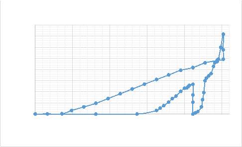 PLA stress-strain graph at 25% (2D graphs)
Stress (MPa)
PLA stress-strain graph at 25% (2D graphs)
Stress (MPa)
Figure A2.(c) PLA at 25% strain cycle 2.
Stress (MPa)
Stress (MPa)
Figure A2. (d) PLA at 25% strain all cycles.
1.3.1 PLA stress-strain-temperature graphs at 50 % strain (3D graphs)
Figure A3. (a) PLA at 50% strain cycle 1.
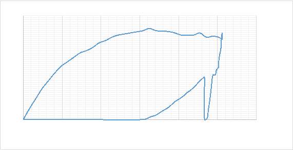 1.3.2 PLA stress-strain graph at 50% (2D graphs)
Stress (MPa)
Figure A3. (b) PLA at 50% strain cycle 1.
2. Constrained Recovery Thermo-mechanical tensile tests for TPU.
2.1.1 TPU stress-strain-temperature graphs at 10 % strain (3D graphs)
Figure A4. (a) TPU at 10% strain cycle 1. Figure A4. (b) TPU at 10% strain cycle 2.
Figure A4. (c) TPU at 10% strain cycle 3. Figure A4. (d) TPU at 10% strain cycle 4.
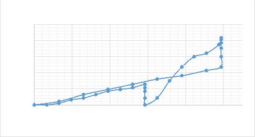 TPU stress-strain graph at 10% (2D graphs)
Stress (MPa)
TPU stress-strain graph at 10% (2D graphs)
Stress (MPa)
Figure A4. (e) TPU at 10% strain cycle 1.
Stress (MPa)
Figure A4. (f) TPU at 10% strain cycle 2.
Figure A4. (g) TPU at 10% strain cycle 3.
Stress (MPa)
Stress (MPa)
Figure A4. (h) TPU at 10% strain cycle 4.
2.2.1 TPU stress-strain-temperature graphs at 25 % strain (3D graphs)
Figure A5. (a) TPU at 25% strain cycle 2. Figure A5. (b) TPU at 25% strain cycle 3.
Figure A5. (c) TPU at 25% strain cycle 4.
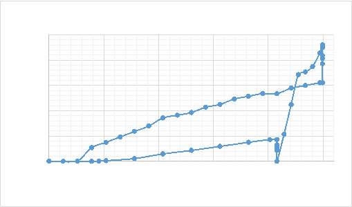 TPU stress-strain graph at 25% (2D graphs)
Stress (MPa)
TPU stress-strain graph at 25% (2D graphs)
Stress (MPa)
Figure A5. (d) TPU at 25% strain cycle 1.
Stress (MPa)
Figure A5. (e) TPU at 25% strain cycle 2.
Figure A5. (f) TPU at 25% strain cycle 3.
Stress (MPa)
Stress (MPa)
Figure A5. (g) TPU at 25% strain cycle 4.
Stress (MPa)
Figure A5. (h) TPU at 25% strain all cycles.
2.3.1 TPU stress-strain-temperature graphs at 50 % strain (3D graphs)
Figure A6. (a) TPU at 50% strain cycle 1. Figure A6. (b) TPU at 50% strain cycle 2.
Figure A6. (c) TPU at 50% strain cycle 3. Figure A6. (d) TPU at 50% strain cycle 4.
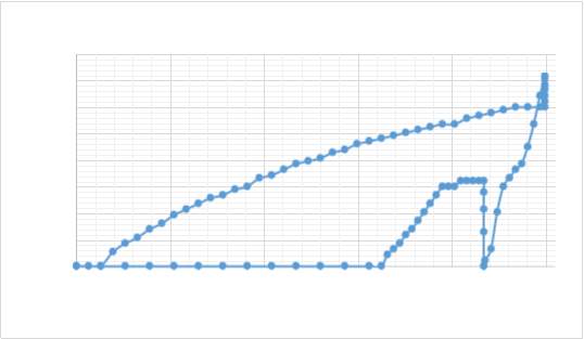 TPU stress-strain graph at 50% (2D graphs)
Stress (MPa)
TPU stress-strain graph at 50% (2D graphs)
Stress (MPa)
Figure A6. (e) TPU at 50% strain cycle 1.
Stress (MPa)
Figure A6. (f) TPU at 50% strain cycle 2.
Figure A6. (g) TPU at 50% strain cycle 3.
Stress (MPa)
Stress (MPa)
Figure A6. (h) TPU at 50% strain cycle 4.
Stress (MPa)
Figure A6. (i) TPU at 50% strain all cycles.
APPENDIX B
Samarth Jain1. Free Recovery Thermo-mechanical tensile tests for PLA.
1.1.1 PLA stress-strain-temperature graphs at 10 % strain (3D graphs)
Figure B1. (a) PLA at 10% strain cycle 1. Figure B1. (b) PLA at 10% strain cycle 2.
Figure B1. (c) PLA at 10% strain cycle 3. Figure B1. (d) PLA at 10% strain cycle 4.
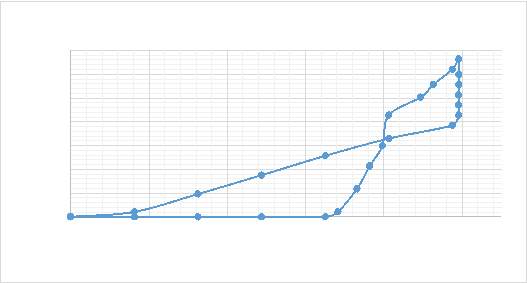 PLA stress-strain graph at 10% (2D graphs)
Stress (MPa)
PLA stress-strain graph at 10% (2D graphs)
Stress (MPa)
Figure B1. (e) PLA at 10% strain cycle 1.
Stress (MPa)
Figure B1. (f) PLA at 10% strain cycle 2.
Figure B1. (g) PLA at 10% strain cycle 3.
Stress (MPa)
Stress (MPa)
Figure B1. (h) PLA at 10% strain cycle 4.
1.2.1 PLA stress-strain-temperature graphs at 25 % strain (3D graphs)
Figure B2. (a) PLA at 25% strain cycle2.
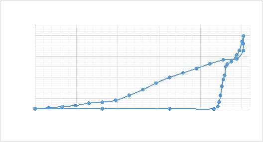 PLA stress-strain graph at 25% (2D graphs)
Stress (MPa)
PLA stress-strain graph at 25% (2D graphs)
Stress (MPa)
Figure B2. (c) PLA at 25% strain cycle2.
Stress (MPa)
Stress (MPa)
Figure B2. (d) PLA at 25% strain all cycles.
1.3.1 PLA stress-strain-temperature graphs at 50 % strain (3D graphs)
Figure B3. (a) PLA at 50% strain cycle 1.
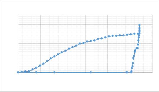 PLA stress-strain graph at 50% (2D graphs)
Stress (MPa)
PLA stress-strain graph at 50% (2D graphs)
Stress (MPa)
2. Free Recovery Thermo-mechanical tensile tests for TPU.
2.1.1 TPU stress-strain-temperature graphs at 10 % strain (3D graphs)
Figure B4. (a) PLA at 10% strain cycle 1. Figure B4. (b) PLA at 10% strain cycle 2.
Figure B4. (c) PLA at 10% strain cycle 3. Figure B4. (d) PLA at 10% strain cycle 4.
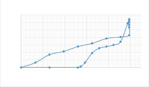 TPU stress-strain graph at 10% (2D graphs)
Stress (MPa)
TPU stress-strain graph at 10% (2D graphs)
Stress (MPa)
Figure B4. (e) PLA at 10% strain cycle 1.
Stress (MPa)
Figure B4. (f) PLA at 10% strain cycle 2.
Figure B4. (g) PLA at 10% strain cycle 3.
Stress (MPa)
Stress (MPa)
Figure B4. (h) PLA at 10% strain cycle 4.
2.2.1 TPU stress-strain-temperature graphs at 25% strain (3D graphs)
Figure B5. (a) TPU at 25% strain cycle 1. Figure B5. (b) TPU at 25% strain cycle 2.
Figure B5. (c) TPU at 25% strain cycle 3.
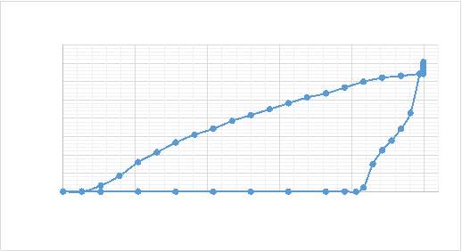 TPU stress-strain graph at 25% (2D graphs)
Stress (MPa)
TPU stress-strain graph at 25% (2D graphs)
Stress (MPa)
Figure B5. (f) TPU at 25% strain cycle 2.
Stress (MPa)
Stress (MPa)
Figure B5. (g) TPU at 25% strain cycle 3.
Figure B5. (h) TPU at 25% strain cycle 4.
Stress (MPa)
Stress (MPa)
Figure B5. (i) TPU at 25% strain all cycles.
2.3.1 TPU stress-strain-temperature graphs at 50% strain (3D graphs)
Figure B6. (a) TPU at 50% strain cycle 1. Figure B6. (b) TPU at 50% strain cycle 2.
Figure B6. (c) TPU at 50% strain cycle 3. Figure B6. (d) TPU at 50% strain cycle 4.
 TPU stress-strain graph at 50% strain (2D graph)
Stress (MPa)
TPU stress-strain graph at 50% strain (2D graph)
Stress (MPa)
Figure B6. (e) TPU at 50% strain cycle 1.
Stress (MPa)
Figure B6. (f) TPU at 50% strain cycle 2.
Figure B6. (g) TPU at 50% strain cycle 3.
Stress (MPa)
Stress (MPa)
Figure B6. (h) TPU at 50% strain cycle 4.
Figure B6. (i) TPU at 50% strain all cycles.
Stress (MPa)
APPENDIX C
1. Risk Assessment
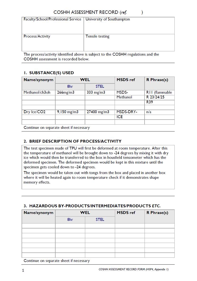 COSHH Form
Cite This Work
To export a reference to this article please select a referencing stye below:
Reference Copied to Clipboard.
Reference Copied to Clipboard.
Reference Copied to Clipboard.
Reference Copied to Clipboard.
Reference Copied to Clipboard.
Reference Copied to Clipboard.
Reference Copied to Clipboard.
Related Services
View all


Related Content
All TagsContent relating to: "Technology"
Technology can be described as the use of scientific and advanced knowledge to meet the requirements of humans. Technology is continuously developing, and is used in almost all aspects of life.
Related Articles

DMCA / Removal Request
If you are the original writer of this dissertation and no longer wish to have your work published on the UKDiss.com website then please: