Parameters and Their Effect on Stiffened Plate Subjected to Uniaxial Compression
Info: 10307 words (41 pages) Dissertation
Published: 16th Dec 2019
Tagged: Sciences
ABSTRACT
A Structure consisting of plates stiffened by a system of ribs or spars have found a wide range of application in ship structures, buildings and other structural engineering fields. It is important to understand the behaviour of such structural elements which can be subjected to continuous loading. One such method to understand to the behaviour is, buckling analysis which is useful to find the critical compressive loads that lead the structure to elastically unstable. In this study, the same method is used for analysing a rectangular plate stiffened longitudinally by T-shaped stiffeners.
The parameters that influence the buckling behaviour and strength of the stiffened plates such as the slenderness and aspect ratio parameters were studied with aid of previous papers. Number of plates with different slenderness ratio was simulated in the Ansys and the possible mode of failure was identified. The aspect ratio parameters were examined with respect to load carrying capacity. The influence of the aspect ratios was obtained using Ansys through simulation of different aspect ratio plates.
Finally, the Stiffened plate with the same dimension but with two different properties with one being square stiffened (line junction) and other being stiffened plate with filleted junction was analysed. In both the cases, the plates were loaded uniaxially by compressive loads. Since both the plates were welded with steel material, welding techniques and its characteristics were discussed in this study with the aid of previous papers. The results such as the change in the behaviour of the stiffened plate due to line junction, displacement, stresses were compared for both the plate properties. All the above topics are analysed independently with different geometrical properties and material of the plate used was steel by keeping the non-parameter values constant.
The investigation of slenderness parameter showed that they have an influence on the behaviour and the strength of the stiffened plate. The aspect ratio has a significant influence on the critical load of the plate, as it reduces with the increase of the aspect ratio. The study of the square and fillet junction of stiffened plate indicated that the plate with line junction proved to be more functional in the critical point as the fillet radius creates more stiffness. The displacement and stress are also found to be in line with the statement above.
Keywords: – Uniaxial loaded rectangular longitudinally stiffened plate, Buckling analysis, Line junction, Fillet junction, Slenderness ratio, Aspect ratio, Finite Element Method software Ansys.
TABLE OF CONTENTS
LIST OF SYMBOLS AND CONVENTIONS
2 CHARACTERISTICS OF FINITE ELEMENT METHODS
2.1 BUCKLING MODES OF STIFFENED PLATES
2.2 WELDING CHARACTERISTICS AND TECHNIQUES IN SHIP PLATES
2.4 STIFFENED PLATE PROPERTIES
2.4.1 GEOMETRY AND MATERIAL PROPERTIES
3 PARAMETERS AND THEIR EFFECT ON STIFFENED PLATE SUBJECTED TO UNIAXIAL COMPRESSION
3.1 EFFECT OF INITIAL IMPERFECTION
3.1.1 INITIAL DEFLECTION AND ITS ESTIMATION
3.1.2 RESIDUAL STRESSES AND ITS METHOD OF APPLICATION
3.2 EFFECT OF SLENDERNESS RATIO
3.2.1 EFFECT OF PLATE TRANSVERSE SLENDERNESS (β1)
3.2.2 EFFECT OF STIFFENER TO PLATE SLENDERNESS RATIO(β2)
3.2.3 EFFECT OF PLATE TO STIFFENER AREA RATIO (β3)
3.2.4 MODELLING OF STIFFENED PLATE WITH SLENDERNESS RATIO
3.3 EFFECT OF ASPECT RATIO ON PLATES
3.4 BUCKLING MODES DUE TO UNIAXIAL COMPRESSION
3.5 ANALYSIS OF SQUARE AND FILLET JUNCTION STIFFENED PLATE
4.1 EFFECT OF SLENDERNESS PARAMETER ON FAILURE MODE
4.2 EFFECT OF ASPECT RATIO PARAMETER
4.3 SQUARE AND FILLET JUNCTION STIFFENED PLATE
5.1 INFLUENCE OF SLENDERNESS PARAMETER ON CRITICAL LOAD OF THE STIFFENED PLATE
5.3 BUCKLING OF SQUARE AND FILLETED JUNCTION STIFFENED PLATE
LIST OF FIGURES
Figure 1. 1:Stiffener system in plates (Rahman, et al., 2015)
Figure 2. 2:Idealised residual stress pattern in the plate with edge weld (Faulkner, 1975)
Figure 2. 3:Typical hungry horse shape by (Carlsen & Czujko, 1978)
Figure 2. 4:Typical Stiffened Plate (Paik, et al., 2011)
Figure 2. 5:Typical plate with compressive loading on longitudinal axis (Sheikh, et al., 2001)
Figure 2. 6: Loading pattern of stiffened plate (Google, n.d.)
Figure 3. 1: Typical plate of Slenderness ratio (b/t) (Google, n.d.)…………………………………………………….
Figure 3. 3:(a) Fillet junction (b) square junction (Patrick E. Fenner & Andrew Watson, 2012)
Figure 3. 4: Geometry of square stiffened plate
Figure 3. 5:Nodal Geometry of the square stiffened plate with boundary condition
Figure 3. 6: Loading direction of the square stiffened plate.
Figure 3. 7: Full view of stiffened plate with filleted junction
Figure 3. 8: Typical stiffened plate with fillet junction (Google, n.d.)
Figure 3. 9: View of part of stiffened plate with filleted junction
Figure 3. 10: Nodal geometry of the filleted junction stiffened plate with boundary conditions
Figure 3. 11:Mapped meshing of the stiffened plate with filleted junction.
Figure 4. 1:Effect of β1 on P when β2 =0.5………………………………………………………………………………………..
Figure 4. 2:Effect of β1 on P when β2 =1
Figure 4. 3:Effect of β1 on P when β2 =1.5
Figure 4. 4:Effect of β1 on P when β2 =2
Figure 4. 5:Effect of β2 on P when β3 =0.3
Figure 4. 7:Influence of aspect ratio on P
Figure 4. 8:Influence of Aspect ratio on deflection
Figure 4. 9:Buckling pattern of square stiffened plate
Figure 4. 11:Behaviour of aspect ratio of square stiffened on stiffened plate deflection
LIST OF TABLES
Table 2. 2: Maximum imperfection in stiffener (Smith, et al., 1991)
Table 3. 1:Initial deflection constant C1 of stiffened steel plate (Paik, 2007c)………………………..
Table 3. 2:Initial deflection constant C2 of stiffened steel plate (Paik, 2007c)
Table 3. 3: Initial deflection constant C3 for stiffener
Table 3. 4: Initial deflection constant C4 of stiffened steel plate (Paik, et al., 2006)
Table 3. 5:Stiffened plate dimensions with respect to aspect ratio
Table 3. 6: Dimensions of square stiffened plate and load applied
Table 3. 7: Dimensions of the Fillet junction stiffened plate with load applied
Table 4. 1:Effect of β1 with β3 = 0.3 on plates with uniaxial compression …………………………..
Table 4. 2:Effect of β2 with β3 = 0.3 on plates with uniaxial compression
Table 4. 3:Effect of β3 on plates with uniaxial compression
Table 4. 4:Initial out of plane deflection of the stiffened plate
Table 4. 5:Plate dimensions for aspect ratio
Table 4. 6:Geometry and results of square stiffened plate
Table 4. 7:Geometry and results of stiffened plate with different fillet radii
LIST OF SYMBOLS AND CONVENTIONS
Ae Area of effective width of the section
Af Area of flange
As Area of stiffener (Af+Aw)
Aw Area of web
a Length of the plate
b Width of the plate
be Effective width of the plate
be´ Plate tangent width
D Bending rigidity
Eh3121-v2
E Modulus of elasticity of material (force/Length)
fr Magnitude of compressive residual stress
fyp Yield strength of plate material
G Modulus of rigidity
E21+v
hf Height of the flange (length)
hw Height of the web
hs Height of the stiffener (length) – (hw+hf)
Ie´ Second Moment of Inertia
K Buckling coefficient
Le Effective length
m Slope of a line or line segment
Mx, My Bending moments (force/length)
r Radius of gyration
Rr Strength reduction coefficient due to welding
td Plate thickness
tf Maximum thickness of flange
tk Corrosion margin
tw Thickness of web
ɳ Residual stress parameter
β Plate slenderness
βe Effective slenderness
λe Slenderness of section as a beam-column
σt Inelastic tripping stress
σu Average stress of collapse
φt Tripping collapse coefficient
φb Buckling strength coefficient
ν Poisons ratio
ϴ Angle (radians)
EXECUTIVE SUMMARY
Chapter 1 deals with the introduction part of the work which starts with the objective of this particular work stating the areas to be studied, followed by the need for this work explaining the necessity for the study in this area and the novelty in this particular project. This chapter also includes a background study explaining all the important and basic concepts behind this work. To have a better understanding to start with, the literature review was done studying all the previous work done in this area and come up with different novel ideas.
Chapter 2 deals with the characteristics of the finite element methods explaining the concept of the finite element method, buckling modes of the stiffened plate. The geometry, material properties, support condition, loading pattern of the stiffened plate procedures are explained which is needed for modelling the stiffened plate in finite element software Ansys. Since welding of plates with stiffener is adopted, the concept of residual stresses and the initial imperfection is also explained in this chapter. Finally, the procedure of modelling the stiffened plate in Ansys software is explained.
Chapter 3 deals with explaining the procedure to achieve the main objectives of the work. To start with, the concept of obtaining the initial imperfection and residual stresses are explained, followed by the influence of two different parameters on the critical load and the deflection of the stiffened plate is explained with the help of Ansys software results. Furthermore, a brief discussion of buckling modes of the stiffened plate subjected to uniaxial compressive load is given before making a comparison of square and fillet junction stiffened plate with the help of same software which is also the main objective of this work.
Chapter 4 deals with the discussion of results obtained in the previous chapter tabulating the results of slenderness ratio, aspect ratio and the comparison of the square and the filleted junction. With the help of tabulation, different graphical representations are prepared in this chapter for better understanding and for deriving a conclusion from these objectives.
Chapter 5 deals with the conclusion and recommendation in which conclusion are made using the results obtained in the previous chapter to achieve the objective of this work. The conclusions include the influence of slenderness ratio parameter and aspect ratio parameter on the critical load and the comparison of the square and the fillet junction stiffened plate with the deflection value and stress values followed by recommendation where some future work can be made related to this particular work which will be helpful and novel.
CHAPTER 1
1 INTRODUCTION
1.1 OBJECTIVE
The objective of this work is to put forward an analysis and comparison of buckling behaviour of two stiffened plate of different geometrical property with one plate having a square junction with the stiffener and the other having filleted junction with the stiffener. Eigen buckling analysis through Ansys mechanical Apdl software was chosen to be used. The deflection and stress values of the stiffened plate were compared for the conclusion. Additionally, the concept of parameters influencing the behaviour and strength of the stiffened plates were taken into consideration and hence the influence of the aspect ratio parameter on the critical load of the stiffened plate and the influence of the slenderness ratio parameter on the failure modes were analysed for the conclusion. All the three objectives were analysed independently.
1.2 BACKGROUND
A structure which is safe in deflection and normal stress fails in buckling. Plates are widely used in the structure which is subjected to continues loading throughout their lifespan. To withstand such a load, stiffeners are introduced which increases the strength, the overall stiffness and provide resistance to buckling. Plates are available in various forms such as rectangular, skew, and curve. There are different types of stiffener system, namely transverse, longitudinal and both transverse and longitudinal system. In this work, rectangular plates with longitudinal stiffener system were used.
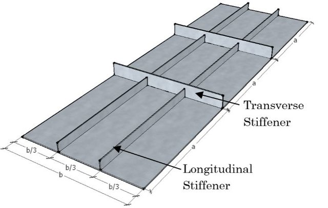
Figure 1. 1:Stiffener system in plates (Rahman, et al., 2015)
The stiffened plate is one of the most basic components among all which is identified in bridges, buildings, aeroplanes, offshore structures. The main difference between the offshore structures and other structure is that the former one experiences In-plane loads in addition to the other loads. Due to their complexity in the structure, the concept of elastic instability has to be studied well to proceed further. To understand the behaviour of the stiffened plate in such loading, buckling analysis is done. Basically, three forms of procedure namely theoretical and/or numerical computer-aided and/or experimental can be adopted. In this work, the numerical computer-aided approach was adopted. The most common computer-aided programming of Finite Element Analysis- Ansys mechanical Apdl was used.
According to the load and the behaviour, the modes of buckling differs namely local buckling, overall buckling, and tripping. The main criteria to prevent the failure was to reduce the overall buckling by confining the plate within local buckling which will increase the stiffness of the plate. The buckling performance can be influenced by variation in cross-section, which suits the case of the stiffened plate with the filleted junction. The geometry of the plate influences the buckling. In such a case, the fillet radii are an important parameter.
Numerical results for both the plate are obtained through Finite Element Program software Ansys and compared for the conclusion.
1.3 NEED FOR RESEARCH
The plates in the ship deck are subjected to continuous loading and are prone to buckling. In such a case, the concept of increasing the thickness or providing the stiffeners to the plate is implemented which will increase the stiffness. On the other hand, stiffened plate on a particular zone can also experience large buckling due to heavy loading by which the introduction of an additional structure such a filleted junction to the stiffened plate can increase the stiffness. This work is important in analysing and comparing both the plates where the previous works identified did rarely used Ansys software for simulation by which this work become unique. Additionally, it is important to understand the behaviour of the stiffened plate on different environmental condition which lies in proportion with two important parameters such as aspect ratio and slenderness ratio. Hence, this work proves to be important for all the structural engineers.
1.4 LITERATURE REVIEW
Razzaque and Mathers (Razzaque & Mathers, 1983), conducted various experiments on the buckling analysis of stiffened plates and shells. Ali Rezo Poladkhan et al (Pouladkhan, et al., 2011), presented a paper in which equilibrium equation was used to analyse the buckling of stiffened plates. Archie Wilmer III (Wilmer III, 2003), presented a paper on buckling analysis of plates with bulb flat flange stiffener and concluded that the former is four per cent less than the T-flange stiffener. Ashutosh kumar, Rachayya R. Arakerimath (Kumar & Arakerimeth, 2015), analytically derived the buckling mode shapes, the nature of buckling using equilibrium method and compared it with finite element approach which was found to be matching. Dr Alice Mathai et al (Mathai, et al., 2014), presented a non-linear buckling analysis of stiffened plate and compared it with finite element software NISA which was found to be convincing. Ghania Ikhenazen, Messaoud Saidani (Ikhazen & Saidani, 2010), used total energy concept to analyse a plot of buckling factor versus aspect ratio and width ratio of an isotropic plate subjected to in-plane loading. Rhodes (Rhodes, 2002), presented a paper on buckling analysis of stiffened plates subjected to local buckling and also concluded that confining the plate the maximum local buckling would prevent the overall buckling. Mudhujit Mukhopadhayay, Abjijit Mukherjee (Mukhopadhay & Mukherjee, 1990), carried out numerical analysis on stiffened iso-parametric and skew plate. The stiffener can accommodate irregular boundaries and the buckling load reduces with the eccentricity of the stiffeners. Seide (Seide, 1953), derived the effective moment of inertia from the effect of eccentricity of the stiffeners. Patrick E. Fenner, Andrew Watson (Fenner & Watson, 2012), presented a work on buckling analysis of the stiffened plate with the filleted junction in aircraft. There is a limit of adding mass at junctions to increase the local buckling stability. The fillet increases the stiffness, however, it also increases the critical buckling stress. He also suggested that a higher fillet size increases the value of K than the upper bound value.
CHAPTER 2
2 CHARACTERISTICS OF FINITE ELEMENT METHODS
2.1 BUCKLING MODES OF STIFFENED PLATES
The failure of the stiffened plate can be in different forms namely local buckling, plate induced failure or stiffener induced failure overall buckling and tripping. Figure 2.1 shows the possible mode of failures in the stiffened plate. Theoretically, the local and overall failure can be identified in all wavelengths but practically it is difficult due to the material strength at that point.
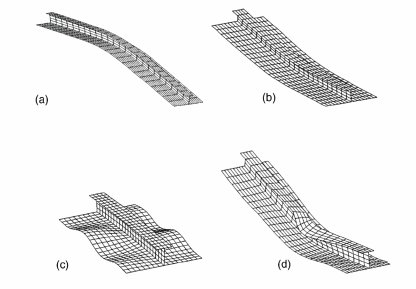
Figure 2. 1:Buckling modes of stiffened plate: (a) Plate induced failure (b) Stiffener induced failure (c) Plate buckling (d) Stiffener tripping (Ni, et al., 2015)
In the local mode of failure, the web line junction does not project to the out-of-plane direction but in some cases there exists where the line junction exits the out-of-plane area. This displacement will be small such as (1/10) th of the overall displacement which strengthens the fact that it does not project to the out-of-plane area.
In the case of overall buckling of plates, the web line junction exceeds the out-of-plane point which means the plate does not lie straight. The projection of the line junction will be in the form of half-wave which looks similar to the half-sine wave. The overall buckling which is also referred as Euler type buckling is a simultaneous failure of both plate and stiffener. If the failure takes place with a stiffener on the tension side, then it is referred to as plate induced overall buckling. On the other hand, if the failure is due to stiffener being on the compression side then it is referred to as stiffener induced overall buckling. Tripping failure of the stiffened plate is lateral torsional buckling which takes place about the stiffener to plate junction. It is actually a sudden drop in load carrying capacity. This type of failure can be serious at times due to the drop in load carrying capacity. It has to be noted that the tripping stiffener experience tension but it may also be subjected to compression due to bending.
In this work, the stiffened plates are subjected to a uniaxial compressive load which allowed to perform analysis in Ansys around the overall or tripping failure.
2.2 WELDING CHARACTERISTICS AND TECHNIQUES IN SHIP PLATES
Welding of ships plates and the stiffener are carried out in two different ways. Continuous welding is used as a procedure to weld the plate and the stiffener which requires huge quantity of weld. It may also add to the weight of the ship and increases the construction cost. Despite increasing the welding quantity, this procedure becomes faster and reduces the labour cost.
Alternatively, the longitudinal stiffeners are attached to plating using intermittent fillet welds. This process reduces the construction cost and also the number of residual stresses when compared to the former welding process.
Welding the stiffener plates effects in both initial distortion and the residual stresses. These two parameters can vary and a number of statistical work has been done in understanding this concept by experts.
Faulkner (Faulkner, 1975), Carlsen and Czujko (Carlsen & Czujko, 1978)and Smith et al. (Smith, et al., 1991), conducted surveys on different structures to assess the above two parameters. Faulkner (Faulkner, 1975)assessed 300 built-in stiffened plates specimens and measured the initial plate distortion.
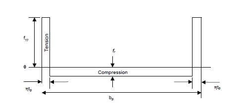
Figure 2. 2:Idealised residual stress pattern in the plate with edge weld (Faulkner, 1975)
Faulkner (Faulkner, 1975) proposed a relationship for
δptd=Kβ2twtd for tw<td and β<3.0
(2. 1)
δptd=Kβ2for tw>td and β<3.0
(2. 2)
Where td is the thickness of the plate,
tw is the thickness of the web,
K is the buckling coefficient of the stiffened plate with 0.12 for warships, 0.15 for merchant ships and it is the function of the aspect ratio and the wavelengths (m).
Faulkner (Faulkner, 1975) also proposed a ‘tension block’ (figure 2.2) relation which would extent from three to six times the thickness of the plate on either side of the weld. The relationship between maximum compressive residual stress in the plate is,
frfrp=2ɳ/(betd-2ɳ
(2. 3)
Where (f)r is the residual stress of the plate,
(f)rp is the stress due to welding,
(b)e is the effective breadth of the plate,
(t)d is the thickness of the plate,
ɳ is the residual stress parameter with value 6-4.5 for ship structures.
Carlsen and Czujiko (Carlsen & Czujko, 1978)studied the magnitude of welding in stiffened plates and found that the slenderness ratio (β²) gave conservative results for slender plates and also proposed a relationship as follows,
δdtd=0.016 bdtd– 0.36 for bdtd>40
(2. 4)
Where
δdis the deflection of the plate,
(t)d is the thickness of the plate,
(b)d is the breadth of the plate.
Carlsen and Czujiko (Carlsen & Czujko, 1978) proposed a ‘hungry hose’ (figure 2.3) along the length of the plate in compression side and a half sine wave across the width of the plate.
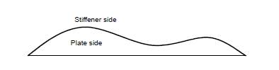
Figure 2. 3:Typical hungry horse shape by (Carlsen & Czujko, 1978)
Smith et al. (1991) grouped the levels of distortions and compressive residual stresses in the plate into average, slight and severs magnitudes corresponding to mean, 3 and 9 percentile values of maximum initial distortion and residual stresses and found that the distortion is proportional to the root of the transverse flexural slenderness. Table 2.1 shows the maximum imperfection and residual stresses in the stiffened plate. Table 2.2 shows the maximum imperfection in the stiffener.
The above studies prove that the welding of ships plating to the stiffeners increase the weight, construction cost but it reduces the cost of labour and construction process faster.
Table 2. 1:Maximum imperfection and compressive residual stresses in stiffened plate (Smith, et al., 1991)
| Level | Maximum initial imperfection | Residual compressive stresses |
| Slight | 0.25β² | 0.05 |
| Average | 0.1β² | 0.15 |
| Severe | 0.3β² | 0.3 |
Table 2. 2: Maximum imperfection in stiffener (Smith, et al., 1991)
| Level | Maximum initial imperfection in stiffener |
| Slight | 0.00025 |
| Average | 0.0015 |
| Severe | 0.0046 |
2.3 FINITE ELEMENT ANALYSIS
Among the various numerical analysis technique namely finite difference method, finite element method and the finite volume method, the finite element method is adopted to analyse the stiffened plates. A description and review of this method to obtain a solution are presented in this chapter.
Finite element method is an approximate technique in which the structure is discretized in a number of segment and treated as an isolated piece. This procedure allows us to model complex geometry and obtain accurate results. If the structure is modelled as isolated geometry and meshed, the structure becomes coarser and it is difficult to obtain accurate results. The main advantage of this method is that the meshing is done in such a way that the continuous domains is discretized into the set of sub-domains. In the case of loading, the loads can be applied to each element which allows to analyse and understand the behaviour of each element separately.
Grondin et al. (1999) validated the experimental data on stiffened steel plates (Grondin, et al., 1999) in their study of stiffened steel plates using finite element modelling. The parameters observed were shape and magnitude of initial imperfection, residual stresses, magnitude and direction of bending, slenderness ratio, aspect ratio, plate to slenderness area ratio.
Grondin et al. (1999) concluded that the above parameters had more influence on the behaviour of the plates and it may contribute to the various modes of failure. The magnitude of the initial imperfection has a direct influence on the capacity of the stiffened plate leading to overall buckling. The strength of the stiffened plate is influenced by the residual stresses leading to plate induced buckling. For the plate slenderness value greater than 1.7, the strength of the stiffened plate is found to be reduced in proportion with the applied compressive residual stress. The plate to stiffener area was found to insignificant. The out-of-plane loading plays a significant part in the modes of failure and the strength of the stiffened plate. The larger the out-of-plane loading, it leads to tripping from plate buckling. All the above conclusion was found to be conservative for ‘average’ magnitude of residual stress and plate imperfections.
2.4 STIFFENED PLATE PROPERTIES
2.4.1 GEOMETRY AND MATERIAL PROPERTIES
The geometry of the plate used in this analysis is the rectangular plate, which is very relevant to the ship and offshore structure. The type of plate used for analysing the square and fillet junction, the influence of aspect ratio and slenderness ratio was a long plate (a>b). This rectangular plate used was stiffened longitudinally and the material used for the stiffened plate was steel, which is in use for the design and fabrication of weight-critical-structures like high-speed vessels.
This study deals with a part isolated stiffened plate in figure 2.4, the length of the plate is ‘a’ and breadth of the plate is ‘b’. The main properties of the plate are the thickness (tk), Young’s modulus and Poisson’s ratio are E and ν. The yield stress is σy. The plate slenderness coefficient (β) given by
β=(bt)√(σyE)
., where, b is the breadth of the plate, t is the thickness of the plate, σy is the yield stressand E is the non-dimensional parameter.
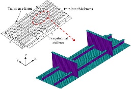
Figure 2. 4:Typical Stiffened Plate (Paik, et al., 2011)
2.4.2 PLATE SUPPORT CONDITION
Although the plates which are surrounded by other plates are either clamped nor supported, it is often assumed that the plates are simply supported as same in this case of the study. The bending rigidity, D is high at the boundary support when compared to the plate itself which implies that the displacement will be low when compared to the plate itself and hence it was assumed that the support remains in-plane.
2.4.3 LOADING PATTERN
The ships can be subjected to in-plane loads and lateral pressure where the former arises due to hull girder structure and the later arises due to the water pressure and/or cargo. In this study, the stiffened plate in the deck of the ship was analysed which means the compressive loading component was chosen for simpler modelling and solving. The potential loading component can be uniaxial, bi-axial, edge shear. Since the plate size is smaller when compared to the structure, the in-plane bending can be neglected. Thus for this study, the uniaxial compressive loading along the longitudinal direction of the pate was adopted for the sake of simplicity.Figure 2.5 shows a typical plate with long dimension ‘a’ and short dimension ‘b’ subjected to uniaxial compressive loading.
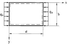
Figure 2. 5:Typical plate with compressive loading on longitudinal axis (Sheikh, et al., 2001)
2.5 FINITE ELEMENT MODELLING
2.5.1 MODELLING
The stiffened plate is modelled with element type shell 3D 4node181 element in the finite element method software- Ansys mechanical Apdl. The material properties such as the elastic rigidity (E) and the poisons ratio (ν) are specified in the linear properties of the model. Since shell element was used, the thickness of the plate was specified in the layup thickness. The exact model of the plate was created as areas by specifying the dimensions of the plate and the stiffener are created as layers. The plate and stiffener were glued finally using the glue command in the modelling part. For the fillet junction of the stiffened plate, the fillet radius is provided at the junction and the geometry was obtained.
2.5.2 MESHING
The modelled stiffened plate is then meshed using mapped mesh the areas of the stiffened plate have been meshed together which allowed the discretising of plates into the set of sub-domains as discussed in chapter 2. The stiffened plate was meshed so that the structure is analysed with absolute accuracy and hence the application of load on the stiffened plate can be dealt with accuracy.
2.5.3 BOUNDARY CONDITION
As mentioned earlier, the stiffened plate was simply supported and the same was followed in the simulations by applying the boundary condition through displacement option in define loads category. The plate is restrained in the all the direction except rotation along the z-axis since it is simply supported. Furthermore, since it is symmetrical boundary condition, an option of symmetrical boundary condition on line along areas was used to restrain the boundaries of the plate.
2.5.4 LOADING
The whole idea of this work was to study the buckling of the plate when subjected to the compressive load applied uniaxial and hence compressive load was applied along the longitudinal direction of the stiffened plate for all the simulation of the different stiffened plate. The load is applied under force or moment option under the structural option of define loads option in the Ansys mechanical Apdl software. The load is applied in the direction of the longitudinal dimension of the plate as shown in figure
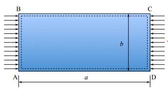
Figure 2. 6: Loading pattern of stiffened plate (Google, n.d.)
2.5.5 SOLVING
The solution of the stiffened plate was obtained through solving option under solve option. Under analysis type, Eigen buckling option was selected for the buckling analysis of the stiffened plate and number of modal results required was specified under solution control option under analysis type. Finally, the whole model was solved for results.
2.5.6 SOLUTION OF THE MODEL
The solution of the stiffened plate can be obtained from the post-processing option. Read results option shows the modal results specified in the above steps. Since most of this work uses the deflection value, through plot results option the deformation of the stiffened plate can be seen with the deflection value and the load factor value. The critical load of the plate was obtained by multiplying the load factor value with the length of the plate. The stress values were obtained by defining element table and simultaneously von Mises stress was obtained.
CHAPTER 3
3 PARAMETERS AND THEIR EFFECT ON STIFFENED PLATE SUBJECTED TO UNIAXIAL COMPRESSION
It is important to know the parameters that influence the possible modes of failure of the stiffened plates. Grondin et al. (1999) determined the parameters that influence the mode of failure in their study. All the above parameters are directly influenced by the failure modes and hence it is necessary to determine the loading condition and modes of failure at first.
The loading of the stiffened plate can be done by two different options such as in-plane and out-of-plane loading. The compressive loading can be done through axial or bi-axial or shear loading. The out-of-plane loading can be done by applying lateral pressure, bending force along the transverse or longitudinal direction. The loading of the stiffened is conventionally done by uni-axial compression force along the direction of the stiffener, which is followed in this work also.
Grondin et al. (1999) determined four different dimensional parameters namely shape and magnitude of initial imperfection, residual stresses, magnitude and direction of bending, slenderness ratio and aspect ratio that influences the behaviour of the stiffened plates. The slenderness ratio allows identifying the behaviour of the stiffened plate subjected to possible failure modes.
3.1 EFFECT OF INITIAL IMPERFECTION
The initial plate imperfections namely, initial deflection and residual stresses are due to the welding of stiffeners to the plate and the welding of the fillet to the plate and the stiffener. These initial imperfections significantly contribute to the reduction in strength and hence these parameters were considered in the design. Since the steel plates were used, the effect of cooling the material in the Heat Affected Zone (HAZ) which is 2bt, was also considered in the design.
3.1.1 INITIAL DEFLECTION AND ITS ESTIMATION
The magnitude and shape of the deflection are important in the buckling behaviour. The magnitude of the initial deflection for the plates is calculated by (Hughes & Paik, n.d.), Table 3 and 4 shows the values of C1 and C2 respectively
wop = wopl
(sin(mπx/a) sin (πy/b)) (3. 1)
wopl = C1 b (3. 2)
wopl = C2 β² t (3. 3)
where wop is the initial deflection of the plate,
wop1 is the initial deflection of the plate due to welding stress,
C1, C2 are constants.
Table 3. 1:Initial deflection constant C1 of stiffened steel plate (Paik, 2007c)
| Level | C1 |
| Slight | 0.0032 |
| Average | 0.0127 |
| Severe | 0.029 |
Table 3. 2:Initial deflection constant C2 of stiffened steel plate (Paik, 2007c)
| Level | C2 |
| Slight | 0.018 |
| Average | 0.096 |
| Severe | 0.252 |
The levels mentioned in table 3.1 and 3.2 are the levels of distortions.
For the initial deflection in the support member (stiffener), the following equation is used,
woc = woc sin
(πxa) (3. 4)
wos = wos
zhsin(πxa) (3. 5)
woc = C3a (3. 6)
wos = C4a (3. 7)
and the table 3.4 and 3.5 shows the values of C3 and C4 respectively.
where woc is the initial deflection of the column,
wos is the sideways initial deflection of the stiffeners,
woc is the sideways deflection of the plate,
wos is the deflection sue to residual stress,
a is the longer dimension of the plate,
C3 and C4 are constants for the plate and the stiffener.
Table 3. 3: Initial deflection constant C3 for stiffener
| Level | C3 |
| Slight | 0.00016 |
| Average | 0.0018 |
| Severe | 0.0056 |
Table 3. 4: Initial deflection constant C4 of stiffened steel plate (Paik, et al., 2006)
| Level | C4 |
| Slight | 0.00019 |
| Average | 0.001 |
| Severe | 0.0024 |
The levels mentioned in table 3.3 and 3.3 are the levels of distortions.
3.1.2 RESIDUAL STRESSES AND ITS METHOD OF APPLICATION
The residual stresses considered in this work was the longitudinal stress arising due to the welding of the plate with the stiffener. The residual stresses are calculated through imposing the initial strains by temperature distribution. Changes in temperature and the initial strains gives rise to the unknown magnitude of initial imperfection.
The residual stresses can be calculated by two different methods namely,
3.1.2.1 2-step method
This method was proposed by Hu, 1993 and Chen el al., 1993 (Kulak G. L, et al., 1993) (Hu, 1993)
The first step is to calculate the temperature distribution (T) from the residual stress,
T=-(frαE)
(3. 8)
Where, (f)r is residual stress,
α is the coefficient of thermal expansion.
The second step is to distribute the residual stresses so that the equilibrium condition ∫ATdA=0 and ∫ATzdA=0 are satisfied.
Initially, apply a temperature change to the stiffened plate mesh corresponding to the residual stress and obtain the deformed mesh. Now the temperature change will produce the required residual stresses and displacement.
3.1.2.2 1-step method
In this method, the residual stress is directly applied to the stiffened plate and the analysis is carried out in the same manner without taking into the account of initial imperfection which will result in a distorted mesh.
It is obvious that this step can be more time saving than the 2-step method.
The effect of residual stresses is obtained by applying the residual stress and the initial imperfection in both the above mentioned steps.
3.2 EFFECT OF SLENDERNESS RATIO
3.2.1 EFFECT OF PLATE TRANSVERSE SLENDERNESS (β1)
Winter (Winter, 1948) presented the results which showed when β1 is less 1.28 the plate could yield fully before buckling. The value of β1 can range from 0.7 to 2.7. As the value of β1 increases, the critical load decreases and fatigue mode changes from plate induced overall buckling to plate buckling. On the other hand, increasing value of β1 does not have an effect on post-buckling behaviour. (Sheikh, et al., 2001)
3.2.2 EFFECT OF STIFFENER TO PLATE SLENDERNESS RATIO(β2)
Plates with a small value of β1 have a constant strength and stable post-buckling behaviour. But larger the value of β1, the strength decreases by which the value of β2 increases. When the value of β2 increases, the strength decreases and the aspect ratio will change. Change in aspect ratio might lead to dual failure of the plate. (Sheikh, et al., 2001)
3.2.3 EFFECT OF PLATE TO STIFFENER AREA RATIO (β3)
Plates with a large value of β1 (i.e.) β1= 2.7, the strength of the plate reduce and it is dependent on β1. The above point proves that the decrease in the value of β3, will reduce the strength of the plate and it is insignificant for smaller β1. (Sheikh, et al., 2001)
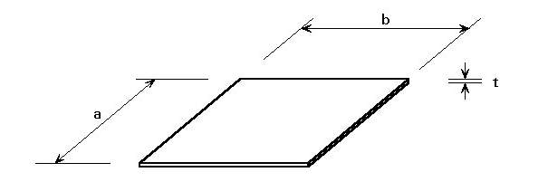
Figure 3. 1: Typical plate of Slenderness ratio (b/t) (Google, n.d.)
3.2.4 MODELLING OF STIFFENED PLATE WITH SLENDERNESS RATIO
To analyse the behaviour of the slenderness ratio parameter on the failure mode, the number of slenderness ratio values of β1, β2, β3 for modelling the stiffened plate were calculated and simulated in the Ansys software. The stiffened plate was modelled and solved according to the procedure mentioned in chapter 2.5. The geometry of the plate and stiffener varies according to the slenderness ratio values in this part of the simulation. The transverse slenderness ratio β1, effect of stiffener to plate slenderness ratio β2 and area ratio between stiffener and plate β3 values are assumed on the first hand. For each of the ratio set’s, the dimensions of the plate are found by using the equations mentioned in figure 3.2. In analysing the parameter β1, the values of β2 and β3 were maintained with the same values for every set of β1 values. In analysing the parameter β2, the values of β3 were kept constant for every set of β1 and β2 values. The stiffened plate was constrained in all the direction except rotation along z-axis since the stiffened plate was assumed to be simply supported throughout the work. A uniaxial compressive force was applied along the longitudinal direction of the plate and Eigen buckling of the plate was observed. The behaviour of the different slenderness values on the failure mode of the plate was observed and respective conclusions were drawn finally.
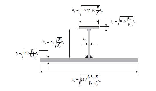
Figure 3. 2:Stiffened plate dimensions expressed in function of slenderness parameters.(Sheikh, et al., 2001)
Where in figure 3.2,
bf is the breadth of the flange,
tf is the thickness of the flange,
hw is the height of the web,
tw is the thickness of the flange,
tp is the thickness of the plate,
bp is the breadth of the plate,
fy is the yield stress,
E is the elastic modulus.
3.3 EFFECT OF ASPECT RATIO ON PLATES
The collapse of the plate and the stiffener subjected to uniaxial compression occur by the combination of plastic yielding and buckling. The geometry of the plate and stiffener becomes more important in such a case which is directly in relation with aspect ratio. Aspect ratio is a parameter which influences the behaviour and strength of the plate, like the slenderness parameter. These values are the result of the members of the longitudinal and the transverse stiffener. When the stiffener plate is subjected to compressive loading, the longitudinal stiffener is provided to prevent the premature buckling of the plate. The longitudinal stiffener is provided with the condition of
bt<80 in this case. The geometry of the plate depends on the results of the aspect ratio and aspect ratios lying between 1 and 4 are investigated in this work.
The plate dimensions are chosen accordingly with respect to the aspect ratio (a/b), the long dimension (a) was fixed as 800mm. The plate slenderness ratio (b/tp) was assumed as 70 and the web slenderness ratio (d/tw) was assumed as 10. The plate to web area ratio is maintained around 0.25 to 0.3. The other material properties of mild steel being yield strength (σ0) = 245MPa, elasticity (E)= 207GPa, poison’s ratio (ν) = 0.3. The uniaxial compressive loading is applied throughout the plate and the results such as the deflection and the stresses were compared. A plot of aspect ratio and critical load is obtained and the conclusion was obtained. The dimensions of the plate with different aspect ratio subjected to uniaxial compressive loading are shown in table 3.5, where α is the aspect ratio (a/b), a and b is the long and short dimension of the plate, tp is the thickness of the plate, d is the height of the web and the tw is the thickness of the web. The stiffened plates were modelled using finite element software Ansys and the procedure of modelling and obtaining solution were followed as explained in chapter 2.5.
Table 3. 5:Stiffened plate dimensions with respect to aspect ratio
| a (mm) | b (mm) | α | tp (mm) | d (mm) | tw (mm) |
| 800 | 800 | 1 | 11.43 | 139.5 | 13.9 |
| 800 | 600 | 1.3 | 8.57 | 122.39 | 12.2 |
| 800 | 450 | 1.7 | 6.43 | 100.87 | 10.09 |
| 800 | 350 | 2.3 | 5 | 81.56 | 8.2 |
| 800 | 250 | 3.2 | 3.57 | 65.26 | 6.5 |
| 800 | 225 | 3.5 | 3.21 | 56.71 | 5.7 |
3.4 BUCKLING MODES DUE TO UNIAXIAL COMPRESSION
When the plate is subjected to uniaxial compression, there are three possible modes of buckling namely, plate induced overall buckling or plate buckling or dual failures. The plate buckling is more common in which the value of β1 can be important than the value of β2. But, higher the value of β2 may induce the overall buckling from plate buckling. When there is a decrease in the value of β3, there is a possibility of dual failure mode. This mode of failure is the buckling which switches to plate induced overall from plate buckling due to the loss in load carrying capacity.
3.5 ANALYSIS OF SQUARE AND FILLET JUNCTION STIFFENED PLATE
The main objective of this part of the study is to compare the behaviour of two plates with the different junction that connects the plate and stiffener with respect to critical load, deflection and stress values. The comparison was carried out through the finite element software Ansys by designing the stiffened plate and solving the same. All the non-dimensional properties were kept constant throughout this part of the study. The figure3.3shows the difference between the square and fillet junction stiffened plate.
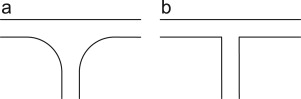
Figure 3. 3:(a) Fillet junction (b) square junction (Patrick E. Fenner & Andrew Watson, 2012)
Initially, a square stiffened plate was analysed since it is a common technique used in the ship constructions. As mentioned in the chapter 2.4.1, long plate i.e. (a/b) > 3 criteria were adopted for the dimension. The dimension of the plate being 2500×800mm with two stiffeners of 200×15mm spaced 267mm apart within the plate. The stiffeners were placed in the longitudinal direction. The boundaries of the plate were constrained as a simply supported and the plate was loaded in the longitudinal direction. The square stiffened plate was then solved for the results consisting deflection, von Mises stress, and load factor value. From the load factor, value the critical load of the plate is calculated for comparison with the fillet junction stiffened plate. Table8shows the dimensions of the square stiffened plate, the load applied to solve the same.
Table 3. 6: Dimensions of square stiffened plate and load applied
| a (mm) | b (mm) | bw (mm) | tw (mm) | tk (mm) | Stiffener spacing (mm) | Load applied (KN) |
| 2500 | 800 | 15 | 200 | 15 | 267 | 500 |
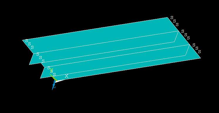
Figure 3. 4: Geometry of square stiffened plate
Figure 3.4 shows the geometry of the plate modelled in the finite element software Ansys mechanical Apdl by the procedure mentioned in chapter 2.5. Figure 3.5 shows the boundary condition of the stiffened plate and as mentioned in chapter 2.5, the modelled stiffened plate is constrained in all the directions except rotation in z-axis in Ansys mechanical Apdl software. The figure 3.6 shows the direction of the loading of the stiffened load.
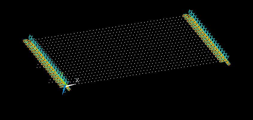
Figure 3. 5:Nodal Geometry of the square stiffened plate with boundary condition
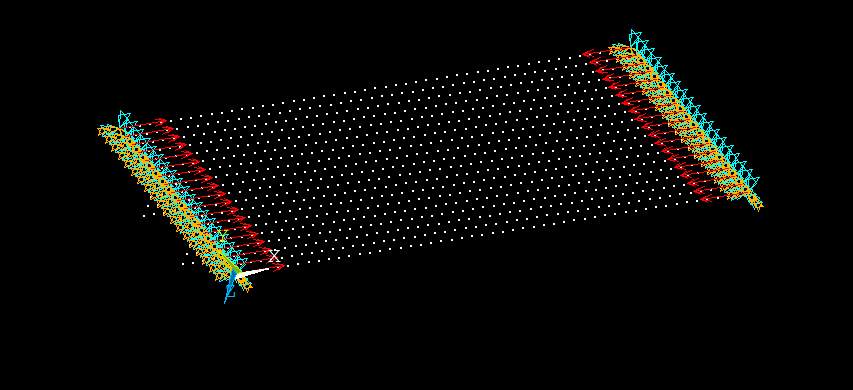
Figure 3. 6: Loading direction of the square stiffened plate.
To compare the behaviour of the square stiffened plate, the stiffened plate with the filleted junctions was solved. The process of solving this plate involved designing of the stiffened plate which was as same as the square stiffened plate but the only difference was the addition of the fillet junction between the plate and the stiffener. As mentioned in chapter 1.2, fillet radii are an important criterion in these cases, it was decided to use four different radii’s of 2mm, 3mm, 4mm, 5mm respectively. Since welding technique for fillet was adopted for the connection of plate and stiffener, the influence of residual stresses was taken into consideration. The residual stresses were calculated from the equation. The residual stresses were applied initially on the fillet junction to allow for the initial deflection. Furthermore, the external load was applied in the longitudinal direction of the plate to calculate the deflection, von Mises stress and load factor values for respective fillet radii stiffened plates and finally, the critical load of the plate was calculated. Table3.7shows the dimensions of the stiffened plate along with the fillet radii and the residual stresses calculated theoretically.
Table 3. 7: Dimensions of the Fillet junction stiffened plate with load applied
| a (mm) | b (mm) | bw (mm) | tw (mm) | tk (mm) | Stiffener spacing (mm) | Fillet radii (mm) | Residual stress (N/mm2) | load applied (KN) |
| 2500 | 800 | 15 | 200 | 15 | 267 | 2 | 27.93 | 500 |
| 2500 | 800 | 15 | 200 | 15 | 267 | 3 | 28.61 | 500 |
| 2500 | 800 | 15 | 200 | 15 | 267 | 4 | 29.56 | 500 |
| 2500 | 800 | 15 | 200 | 15 | 267 | 5 | 30.78 | 500 |
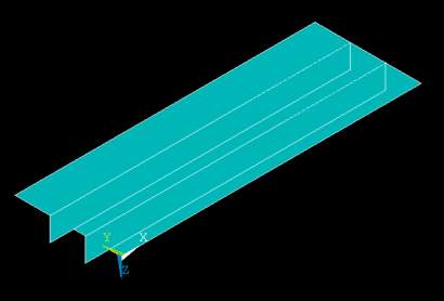
Figure 3. 7: Full view of stiffened plate with filleted junction
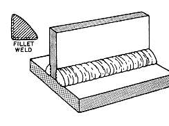
Figure 3. 8: Typical stiffened plate with fillet junction (Google, n.d.)

Fillet junction
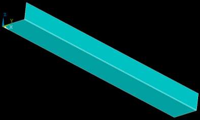
Figure 3. 9: View of part of stiffened plate with filleted junction
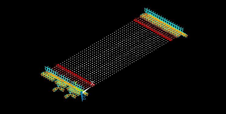
Figure 3. 10: Nodal geometry of the filleted junction stiffened plate with boundary conditions
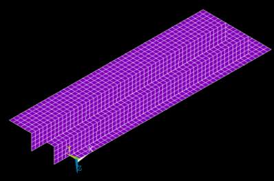
Figure 3. 11:Mapped meshing of the stiffened plate with filleted junction.
The figure 3.7 shows the view of the stiffened plate with filleted junction modelled in the Ansys mechanical Apdl software using the fillet area command under area topic. The figure 3.8 shows a typical fillet junction welding to the stiffened plate. The figure 3.9 shows a part of the stiffened plate pointing the fillet junction with specific radius. The figure 3.10 shows the geometry of the stiffened plate in nodal view with the plates being constrained in all the directions except in the direction of rotation along z-axis and direction of loading of the stiffened plate. The figure 3.10 shows the mesh of the modelled stiffened plate using the command of mesh in the software.
Cite This Work
To export a reference to this article please select a referencing stye below:
Related Services
View all


Related Content
All TagsContent relating to: "Sciences"
Sciences covers multiple areas of science, including Biology, Chemistry, Physics, and many other disciplines.
Related Articles

DMCA / Removal Request
If you are the original writer of this dissertation and no longer wish to have your work published on the UKDiss.com website then please: