System Design for Universal Rental System
Info: 18123 words (72 pages) Dissertation
Published: 10th Dec 2019
Tagged: Information Systems
CHAPTER-1
INTRODUCTION
- PROJECT DISCRIPTION
Universal Rental System is a web application. The application is mainly used to reduce the distance between vendors and customers. This project is designed to be used by any users for renting their products. It is an online process to which customers can register and view the available products and then book the products. There are many rental systems which are available online, that provide only one type of product at one place. But this application is used for renting more than one type of products at one place. This system is developed for renting machinery, house and vehicle.
The project is based on Admin, Vendor and customer. Admin can view the requests details send by the customer for their product. Admin will check whether the product is available and change the status such as whether the product is sold or available, admin will send a mail to authenticate the customer. Admin can also view the product that is uploaded by vendors. He can view the feedbacks send by the users. The main process of the admin is to control the entire system and deals with the customers. The process of the admin user is sending the notifications to the vendors and customers.
Vendor should first register to the system by giving their details. Vendor logins to the system and can upload their property into the site. Vendor can view all the products they have uploaded. They can view the requests for their product. Vendor can also send feedback to the site.
Customer can register to the site and search for any property they want. And then send request to admin for that particular product. Customer can ask for help with admin. Customer can also send feedback to admin.
Purpose of the project is,
- To transport the goods from one place to other in an effective and efficient manner.
- This application is acting as interface between vendor and customer there is no restriction that any vendor wants to display their product in our site.
- It gives the some extra features for vendors to edit or delete products.
- Admin can see all the customer details and also view the all transaction details of the customer and vendor.
- COMPANY PROFILE
First Global Software was started in 2004 as a software development company at Bangalore, India. Set up with a single goal and a direction, namely, making quality work for the customers. Today it have clients who are located in India and Abroad.
First Global Software Service global renowned software service company that specializes in providing a complete range of software services and solutions. Company has been promoted by some highly experienced professionals dedicated to provide total IT solutions under one roof.
The services which are provided by the company includes
- Software Development
- Software Testing
- Application Development
- Portal Development
- IT Outsourcing
- Mobile Apps Development
- Avionics
Now First Global software has its expertise in the field of Software Development, Telecom testing and Development, web designing, hosting solutions, Extranet and Intranet Applications, Smart cards and security solutions.
CHAPTER-2
LITERATURE SURVEY
2.1 INTRODUCTION
In literature survey develop a model to overcome the limitations of existing system, it also helps to study the existing system in details. There are many websites are available for renting products and booking those systems were studied and new thinks are found which are added to this rental system.
2.2 EXISTING SYSTEM AND PROPOSED SYSTEM
There are only few portals available that provides the online renting of properties. The existing system does not have the option for sending mail to the customers. Most of the system are only concerned with a particular single property.
The proposed system is developed to overcome the limitations of existing system. The proposed system is a renting system for different types of properties.
The system include search option based on location, agent name etc. It includes automated email facilities.
2.3 FEASIBILITY STUDY
During the feasibility study, the feasibility of the project- the likelihood of the proposed system is analyzed. The feasibility study was carried out on the overall integrated package.
There are three ways of feasibility study that is
- Technical feasibility
- Economical feasibility
- Operational feasibility
Technical Feasibility
Technological feasibility analyses the following areas:
- Technology and manpower is available are not.
- Capacity to hold the data that is required to use the new system.
- Provision to respond to users regardless of their number and location.
Economic Feasibility
Issues to be considered in the economic feasibility are:
- Financial benefits must equal or exceed the costs.
- The solution should be cost effective.
- Must be worth to pursue the project.
Operational Feasibility
The main objective here is to find out whether
- The system will work once it is developed and installed.
- There is sufficient support for the project from the management.
- The current business methods are acceptable to the user.
2.4 TOOLS AND TECHNOLOGY USED
JAVA
Java is used as front end tool for developing this project. Java is platform independent, so there is no need to have any particular operating system to run java program. It must have some hardware and software installed in the computer. Some of the features of java are simple, secure, portable, object oriented, robust, multithreaded, distributed etc.
HTML
HTML stands for Hyper Text Markup Language. HTML was developed specifically to create documents for display on the World Wide Web. It is used along with the Hyper Text Transfer Protocol (HTTP). It is defined within the HTML standard which are recommended by the W3C HTML is not a programming language and it cannot be used to write programs.
MySQL
MySQL is the database management system. It is the most popular open source database. It was developed, distributed and supported by MySQL Lab.
Database means structured collection of important data. To access, process and operate data stored in a computer database, we must require a database management system such as MySQL server. A relational database stores data in different relational table instead of storing all data’s in a single big showroom.
2.5 HARDWARE AND SOFTWARE REQUIREMENTS
Software Requirements
| Operating System | : Windows 7 and above |
| Front end | : Java, HTML, JSP |
| Programming Language | : Java |
| Database | : MySQL |
| IDE | : Eclipse |
Hardware Requirements
| Processor | : Pentium(IV) or higher |
| Memory | : 500MB or higher |
| Hard Disk Capacity | : 500GB Hard Disk or more |
| Speed | : 1.1GHz |
CHAPTER-3
SOFTWARE REQUIREMENTS SPECIFICATION
3.1 USERS
The system is designed in a way that provides a friendly way to use the system so that it will be easily understood and no training for operation is needed.
The system allows three types of users to use the system namely
- The Vendor
- The Customer
- The Admin
Vendor: Vendor is the property owner who advertises his property in the website. He first registers into system and then uses the website. In order to upload his product first he needs to login to the site by providing correct username and password.
The vendor should be able to
- Upload Property:
Vendor can upload their property into the site with essential details.
- View property:
Vendor can view all the property he has uploaded.
- Registration:
Vendor first registers to system by giving the details.
- Update property details:
Vendor can update the details of property that is uploaded.
- Send feedback:
Vendor can send feedback to admin
Customer:Customers are the registered users. They login to system and search for the products. If the required product is available customer can request to admin to book the product. Customer can also send feedback to admin.
The customer should be able to:
- Registration:
Customer registers into the site by providing the details.
- Search product:
Customer can search the properties based on location, agent name etc.
- Ask for help
Customer can ask for help with the admin to know the booking process.
- Send feedback:
Customer can also send feedback to admin.
Admin:Admin in this system has the rights to view the products uploaded by the vendors and request send the users. According to the request by the user admin will send an alert message to vendor that his or her product has been requested for rent.
The admin should be able to:
- View Request:
Admin can view the request send by the customers.
- Send Alert:
Admin can send alert to the agent if a request has arrived for the product of that agent.
- View properties:
Admin can view all the properties that have been updated by all the agents.
- View Feedback:
Admin can view the feedbacks send by both the vendors and customers.
3.2 FUNCTIONAL REQUIREMENTS
Functional requirements will describe the behaviors of the system. And also it will describes with the system should do. These functional requirements will specify what output should be displayed for the given inputs. Invalid inputs are not allowed in the system.
According to the data type all inputs are entered, and for mandatory field no blanks are allowed.
Invalid inputs is not allowed in the system; if there is any fault the system will notify the user by giving a message.
If any unique id or name is repeated in the same record then database should alert a message.
The system should check all the necessary fields whether it is filled or not, if the field is not filled a message should be given by the system.
The system should switch from one page to another whenever the user will trigger a button or link.
The system should send a message whenever a user presses the button.
System should insert the new records when requires.
System should update the database and display the records if it necessary.
Appropriate error messages are displayed. It prompts to re-enter the data.
3.3 NON-FUNCTIONAL REQUIREMENTS
Non-functional requirement indicates the essential non-functional operational requirements of the Universal Rental system. These requirements will specify the performance of the system.
- User friendliness: Universal Rental System is designed for users to easily book their needed product for rent. The system should be user friendly so that the booking process can be managed in a simplified process.
- Operability: The system should be operational that the system can be used in any windows platform with compatible framework.
- Response Time: Response time of the system should match up to the operational level criteria. The instructions given to system should execute and produce result in time.
- Efficiency: The system should be efficient. It should use all the resource allocated.
- Security: Security of system is essential for the customers that it should protect itself from malwares and security threats.
- Compatibility: The system should always run in all compatible operating system environments.
CHAPTER-4
SYSTEM DESIGN
4.1 INTRODUCTION
System design is mainly deals with the solution for the problem specified by the requirements.
In this level the different types of methods are used for solving the problem such as subsystem design, architectural design and system decomposition etc.
4.2 SYSTEM PERSPECTIVE
The proposed rental system will take care of all the three users. Admin, vendor and the customer. The system inputs and outputs are well designed so that the system can create a new user and the manage admin activities. The customer can design to the system anytime and search and book the products for rent.
Input Design
The main purpose of input data design is to enter the data more easily and make it as free from bugs. The well design input forms makes the input data error free. Textbox, drop-down list, radio button, checkbox, command button and link button are the common input method as used in the system to get the correct details of the data.
All fields in the form are properly labeled and it is more understand for the customer, what they need to enter. This process is done through online. The system accepts input data and commands through a keyboard.
Some of the following rules are:
Each fields are clearly specified with label with specific name
Type mismatch will indentified and alert by validators
The field length should be documented
User can modify the data before sending to the system
Provide proper instruction to the user for what kind of data to be inserted in the field
Output Design
Output design provides the right processed information to the right user at right time in the right format by the system. Outputs are the proper result of processed user command and input data which is validated by the system.
Different Output methods are used in the Universal Rental System. The following are the main output design used in this system.
Grid View
Data List
Text View
System will processes the user input according to the program and commands and produces appropriate output as the formatted result in user readable format. The result may be a portion of the database which contains the number of fields in a table. The output will be displayed using different output option available like Text box, Grid View.
4.3 CONTEXT FLOW DIAGRAM (CFD)
Context flow diagram (CFD)is one of the top level data flow diagram which shows the entire function of system. Context flow diagram contains one process node and related external entities.
Admin


Request Response
Universal Rental Capture

 Request Request
Vendor
Customer


Response Response
Fig:: CFD (Context Flow Diagram)
This diagram shows the entire functions of the system, where Universal Rental System is the process node which will interact with the users such as Admin, Vendor, Customers. System (Universal Rental Capture) will accept the request from the external entities and process it. The response will be send back to those entities.
Request from the users includes different types of functions such as inserting, editing, updating, viewing etc. The system processes the queries and send those results back to the users. The results may be view a portion of the database or updated database.
4.4 DATAFLOW DIAGRAM
Data flow diagram shows how the data flow in the system.
LEVEL 1
Username and password
Login
Admin


 Invalid username and password
Successfully login Logout
Admin Home


View Report
View User
View Vendor
View or Response feedback
View Query


 Retrieve Retrieve Retrieve retrieve update retrieve update
User Agent Agent Query
Report

Level one of the DFD shows the how the flow of the data from the admin. Admin should enter the correct username and password. If it is matches in the database then it will directed to the next stage. If the username or password mismatches in the database then it will not proceed to the next page. If it is valid the system will redirected to admin home page. Admin can perform the different operations there, such as view report, view user, view vendor, view or response feedback, view response query. Once the process is complete then admin can go back to initial stage.
LEVEL 2
 Username and password
Vendor
Login
Registration


 Invalid username and password
Logout
Vendor Homepage


Request help
Request feedback
View website money
Upload Property
Request/ Response property


 update retrieve update update retrieve update update
Properties Properties Help Feedback Expence
Second level of the DFD shows the how the flow of data from the vendor to the system. Vender first registration, then enter the correct username and password to login. It will match in the database. If it is invalid it will not proceed with the next page. If the valid details are entered system will redirected to vendor home page. The vendor will perform the several operations like upload properties, request/response properties, request help, request for feedback, view website money.
LEVEL 3
Username and Password
Login
Customer
Registration


Successful login Unsuccessful login
Customer Home Page


View/Generate report
Request property
Give Feedback
Chat
Help
Search property


 update retrieve update retrieve update retrieve update
Properties


 Properties Feedback Chat Report Feedback
Third level of the DFD shows the how the flow of data from the customer to the system. Customer first does registration, then enter the correct username and password to login. It will match in the database. If it is invalid it will not proceed with the next page. If it is valid the system will redirect to customer home page. The customer will perform the several operations like request property, help, chat, view or generate report, give feedback.
CHAPTER-5
DETAILED DESIGN
5.1 INTRODUCTION
In the detailed design part, the detailed structure of each module are designed. Detailed design is the extension of system design and is used to identify the logic of the modules.
There are four types of diagrams that come under detailed design. They are: Use case diagram, Sequence diagram, activity diagram and E-R diagram.
5.2 USE CASE DIAGRAM
The Use case diagram clearly shows the interactions between the users and the system. In this system, there are 3 users that includes in different use cases. Admin, customer and vendor are the three users those interact with the system use cases.
Login
The login use case give details about the login process of users in the system. System checks the username and password for each user.
Actors
The actor use case shows the interaction between the external users and the system. An actor is an external user such as a person or an organization.
In universal rental system, the actors are customer, vendor and admin. Admin can perform the activities such as view request, view property, send alert and view feedback. Vendors interact with the system and perform the activities like uploading property, viewing property, updating details, send feedback. Customers interact with the system to search property, buy property and send feedback.
Use case
The use case is a list of steps that shows the interaction between the user and the system. A horizontal ellipse is used to indicate a use case.
Some of the use cases used in the universal rental system are
- Register
- Upload property
- Search property
- Buy property
- View property
- Send feedback
- View request
- Send alert
Connectors
Connectors which are represented by arrows are used to connect the actors with the different use cases in the system. It clearly describes the information flow in the system.


Register
Login


Login


View Report
Request


Search
View user


Request Query
 Customer Response/View
View Vendor
Request view/ Response help


 Admin
Admin
Response Feedback
 View
View
Feedback
Vendor
View/ Response query
Chat
View / Generate
View website income
Upload
View website income
Use case Diagram
5.3 SEQUENCE DIAGRAM
Sequence diagrams are the interaction diagrams that describes how each objects of the system depends to the other objects and how and what order does they operate. It shows how the objects interact according to the time. I can also find the series of messages that are transferred among the objects. The sequence diagram is also called as event diagrams or event scenarios.
In the sequence diagram, there will be a user, system and the database. There should be sequence diagram for each user. The sequence diagram a particular user describes how the user interacts with the system and what actually the user does in the system. Therefore, it can be said the sequence diagrams are used to describe the overall working of the system.
Admin
System
Database


 View Request Request details


 Display all the Request
 View Product Product Details
Display all product


Solve Query Required Details
Query is responded Validation

View Feedback Feedback details
Feedback is displayed
Fig: Sequence diagram for admin
Sequence diagram describes the interactions between the participants.
- Admin indicates to enter to the system
- Admin enters the username and password
- System verifies the admin details
- System displays the admin page
- Admin inputs will be processed by the system
The admin interact with the system by enter the valid username and password. If it is correct the admin will goes to admin home page.
Admin can view the report for all the properties by clicking the view report button and he can also view the all the customer and vendor who are registered with our site. And admin can view customer feedback and vendor feedback and also response them, and at last view the queries of customer and vendor and response for that.
System
Database
Vendor


 Upload Property Property Details

 Property is uploaded Validation


View Property Property Details
Display uploaded Property Validation

View Request Request details

 Displays requests Validation
Give feedback Required fields
Feedback is sent Validation
Fig: Sequence diagram for Vendor
The Vendor interact between participants
- Vendor first register with the system by entering the valid username and password.
- Then upload the property to the system
- After uploading they can view the property
- Then view request details
- And give feed back to the system
System
Database
User


 Registration Username,Password


 Account is registered Validation
Login Username, Password

 Login Successfully Validation
View Product Product details

 Displays product details Validation
Send request Product details
 Request is send Validation

Ask for help Required fields
Validation
Add comment Comment details
Comment is sent Validation
Fig : Sequence Diagram for Customer
User sequence diagram interact between the participants
- Customer first register with the site
- After register they can enter valid username and password
- Then system verifies the user authentication
- The system will display main page
- Then customer input data
- And it will be proceed, result send back to the Customer
5.4 ACTIVITY DIAGRAM
Activity diagram are the diagrams that are used to indicate the dynamic features of the system. It shows the flow of actions that happens in the system.


 Customer has already registered Customer has not already registered


Click register
Login

Fill registration form
Perform action


Form is valid Form is invalid


Submit registration form


Logout


In the above diagram there is starting and ending nodes are there. This shows the activities are performed in the system.
- It starts with the login and registration
- If the customer is already registered, then they can login to the system by giving username and password
- Otherwise the system goes to registration
- At last system enters to logout
5.5 DATABASE DESIGN
ER-Diagram
The Entity Relationship diagram depicts how the entity sets and their relationship relates in the system. ER diagrams are used to understand the logical structure of the database. The entities are represented by rectangular box and relationships are represented by diamond symbol. Each entity will have many attributes that are represented by ellipse. This system contains mainly three entities. Admin, Customer, Vendor.
Each entity is related with one another. For example the admin entity is related with customer and vendor by viewing their accounts and performing their profit and loss based on their details.


Password
Password
Username
UserName


address

N
1
Vendor
Manages


Admin
a
Password


UserName
View
Upload product

 N N
N N
address
User
View


Money
PropName
PropID


 N
N
Price
Account Amount
View

 Pri N
Pri N
Property
View
Sold Property
Address


 1 1 N
1 1 N
PropName
BookID


Apperence
Price
Send ID
Query
Request
Book


 N
N
View
Solve Query


 1
1
Payment
Generate Report
RecieptID


Solution
Ask


Query
Give
Feedback


Upload product


Sold Product
Profit

Date
Give
Net Profit
Suite Income
Generate Report


Fig: ER diagram
Conceptual schema
Table Name: User Login
| Field Name | Data Type | Constraints | Description |
| Username | varchar(100) | Not Null | Username |
| Password | Varchar(100) | Not Null | User Password |
Table Name : User Registration
| Field Name | Data Type | Constraints | Description |
| Name | varchar(100) | Null | Name |
| Username | varchar(100) | Not Null | Username |
| varchar(100) | Not Null | ||
| Password | varchar(100) | Not Null | Password |
| Phone | varchar(100) | Not Null | Phone |
| Address | varchar(100) | Not Null | Users Address |
Table Name: Buy Property
| Field Name | Data Type | Constraints | Description |
| H_ID | int(15) | Not Null | H_ID |
| Reg_Date | varchar(100) | Not Null | Registration Date |
| Username | varchar(100) | Not Null | Username |
| varchar(100) | Not Null | ||
| Subject | varchar(100) | Not Null | Subject |
| Comment | varchar(100) | Not Null | Comments about property |
| Status | varchar(100) | Not Null | Property Status |
| Answer | varchar(100) | Not Null | Answer |
Table Name: Book Property
| Field Name | Data Type | Constraints | Description |
| PB_ID | Int(15) | Not Null | Property Book ID |
| Book_Date | Varchar(100) | Null | Booking Date |
| P_ID | Varchar(100) | Null | Property ID |
| AgentName | Varchar(100) | Null | Agent Name |
| LandName | Varchar(100) | Null | Land Name |
| Price | Int(15) | Null | Price of the property |
| Your_Price | Varchar(100) | Null | Your Price |
| Difference | Varchar(100) | Null | Difference |
| UserName | Varchar(100) | Null | Name of the user |
| Varchar(100) | Null | Mail id of the user | |
| Status | Varchar(100) | Null | Status of the property |
| Comment | Varchar(100) | Null | Comments about the property |
| Message | Varchar(100) | Null | Message |
Table Name: Buy Machinery
| Field Name | Data Type | Constraints | Description |
| Mbid | Int(15) | Not null | Buy machine ID |
| Mid | Int(15) | Null | Machine ID |
| Book_Date | Varchar(100) | Null | Date of book the machine |
| Category | Varchar(100) | Null | Category of the machine |
| Product_Name | Varchar(100) | Null | Name of machinery product |
| Price | Int(15) | Null | Price of the product |
| Agent-Name | Varchar(100) | Null | Agent name |
| Description | Varchar(100) | Null | Description about product |
| Comment | Varchar(100) | Null | Comments |
| Username | Varchar(100) | Null | Name of the user |
| Varchar(100) | Null |
Table name : Machinery
| Field name | Data Base | Constraints | Description |
| Mid | Int(15) | Not null | Machine ID |
| Date | Date | Null | Date |
| Category | varchar(100) | Null | Category of the machine |
| Pname | Varchar(100) | Null | Product Name |
| Description | Varchar(100) | Null | Description of the machine |
| Address | Varchar(100) | Null | Address |
| City | Varchar(100) | Null | City where located |
| Price | Int(15) | Null | Price of the product |
| Keyword | Varchar(100) | Null | Keyword which used to search |
| Image | Longblob | Null | Image of the product |
| Status | Varchar(100) | Null | Status of the machine |
| Agent Name | Varchar(100) | Null | Agent name |
| Varchar(100) | Null |
Table Name: Property
| Field Name | Data Type | Constraints | Description |
| Pid | Int(15) | Not Null | Property Id |
| Category | Varchar(100) | Not Null | Category of the property |
| Landname | Varchar(100) | Not Null | Land name of the property |
| Location | Varchar(100) | Not Null | Location where the property located |
| Address | Varchar(100) | Not Null | Address of the property |
| Price | Varchar(100) | Not Null | Price of the property |
| Keyword | Longblob | Not Null | Keyword |
| Image | Longtext | Not Null | Image of the property |
| Description | Varchar(100) | Not Null | Description about property |
| Status | Varchar(100) | Not Null | Status of the property |
| Agent Name | Varchar(100) | Not Null | Agent Name |
| Date | Varchar(100) | Null | Date |
| Varchar(100) | Null |
Table Name : Vehicle
| Field Name | Data type | Constraints | Description |
| Vid | Int(15) | Not Null | Vehicle ID |
| Rdate | Date | Not Null | Date for rent |
| Vdrname | Varchar(100) | Not Null | Vdrname of the vehicle |
| Category | Varchar(100) | Not Null | Category of the vehicle |
| Cname | Varchar(100) | Not Null | Customer name |
| Vname | Varchar(100) | Not Null | Vehicle name |
| Vnum | Varchar(100) | Not Null | Vehicle number |
| Address | Varchar(100) | Not Null | Address |
| Pdate | Date | Not Null | Pdate of the vehicle |
| Description | Varchar(100) | Not Null | Description of the vehicle |
| Rent | Varchar(100) | Not Null | Rent for vehicle |
| Keyword | Varchar(100) | Not Null | Keyword used for vehicle |
| City | Varchar(100) | Not Null | City |
| Image | Longblob | Not Null | Image of the vehicle |
| Status | Varchar(100) | Not Null | Status of the vehicle |
| Agentname | Varchar(100) | Not Null | Agent name |
Table Name : Feedback
| Field Name | Data Type | Constraints | Description |
| Username | Varchar(100) | Null | User name |
| Varchar(100) | Null | ||
| Subject | Varchar(100) | Null | Subject |
| Comment | Varchar(100) | Null | Comment |
Table Name: Buy Vehicle
| Field Name | DataType | Constraints | Description |
| Bvid | Int(15) | Not Null | Buy vehicle ID |
| Vid | Varchar(100) | Not Null | Vehicle ID |
| AgentName | Varchar(100) | Not Null | Agent Name |
| Vnumber | Varchar(100) | Not Null | Vehicle Number |
| Rent | Int(15) | Not Null | Rent of the vehicle |
| Username | Varchar(100) | Not Null | User name |
| Varchar(100) | Not Null | ||
| Days | Varchar(100) | Not Null | Days |
| Total Amount | Varchar(100) | Not Null | Total Amount |
| Book Date | Varchar(100) | Not Null | Book Date |
| Status | Varchar(100) | Not Null | Satus of the vehicle |
Table Name: Agent
| Field Name | Data type | Constraints | Description |
| Agent ID | Int(15) | Not Null | Agent Id |
| Agent name | Varchar(100) | Not Null | Agent name |
| Varchar(100) | Not Null | Email of the agent | |
| Password | Varchar(100) | Not Null | Password |
| Phone | Varchar(100) | Not Null | Phone number |
| Address | Varchar(100) | Not Null | Address of the agent |
| Expdate | Varchar(100) | Not Null | Exp date |
| Date | Varchar(100) | Not Null | Date |
Table Name: Amount
| Field Name | Data type | Constraints | Description |
| ID | Int (15) | Not Null | ID number |
| Date | Varchar(100) | Null | Date |
| Total Amount | Int(15) | Null | Total amount |
| Tax | Int(15) | Null | Tax |
| Site Tax | Int(15) | Null | Site Tax |
| Vendor_Money | Int(15) | Null | Vendor Money |
CHAPTER-6
IMPLEMENTATION
6.1 INTRODUCTION
The system is implemented after the document phase is completed. In the implementation stage, the plans and concepts are changed to reality.
6.2 SCREEN SHOTS
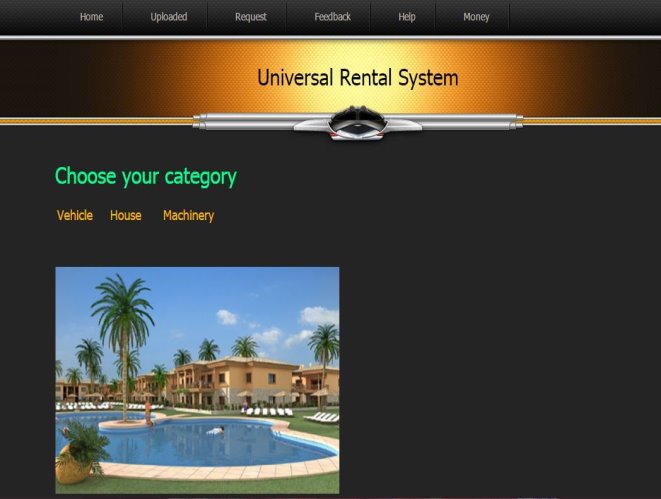
Home Page
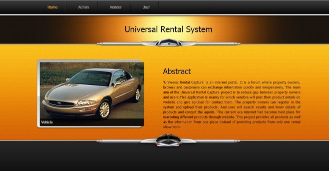
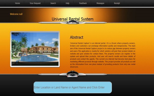
This is the home page. This page provides many links for system users such as admin, vendor and customer login by click these links it will provide their home pages.
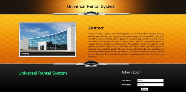
Admin Login
In this page admin can login and accessing other pages. If entered data are match with database value it will redirecting admin home page or else system will display error message.
Admin Home Page
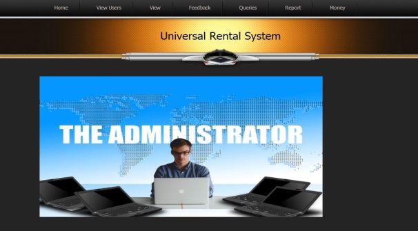
This is the admin home page. This page provide many options to admin such as view website users, view messages, user queries , report based on date etc.
Vendor Registration Page
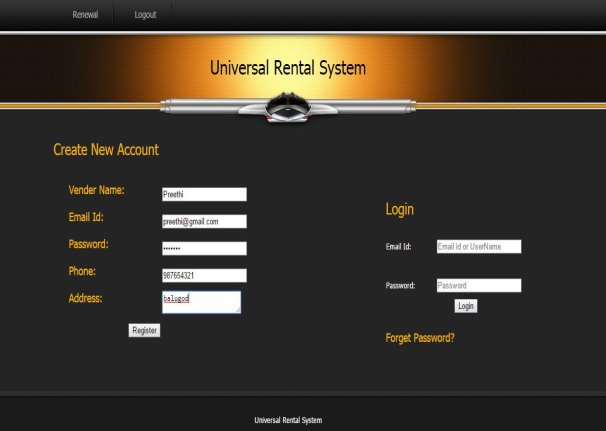
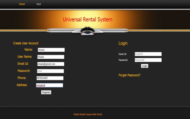
This is the vendor registration and login page. The new vender can register in this page, by entering all the fields. Registered vendor also login in this page by using valid username and password. It contains renewal account link.
Vendor Home Page
This is the vendor home page. This page contains uploaded, request, feedback, Help, Money links are there. Here mainly vendor can upload their properties and also he can view the request which is send by the user.
Upload Vehicle Page
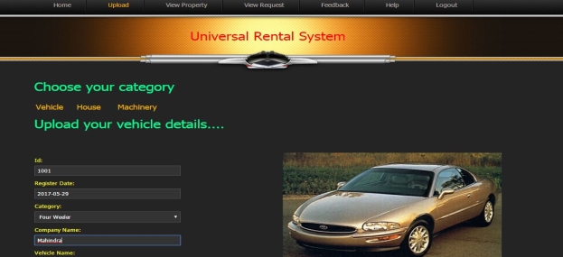
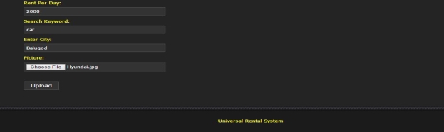
This is the upload vehicle page. Vendor can upload there vehicle by a filling given fields and click the upload button. By clicking the upload button, successfully uploaded message can be show.
Upload Property Page
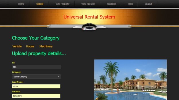
This is the upload property page. Vendor can upload their property by a filling given fields and by clicking the upload button, successfully updated message can be show.
Feedback Page
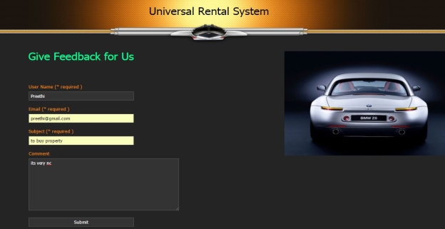
This is the feedback page. Here user and vendor can give their feedback for the website. By clicking submit button it display message as successfully registered.
Help Page
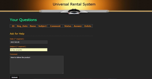
This is the help page for user and vendor. Here he can submit his query for vendor. He can also view his required query which is solved by admin.
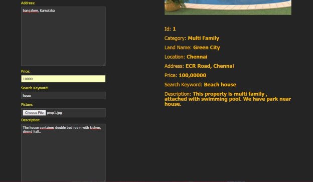
User Home Page
This is the registered user home page. It contains several links that is your request, search, help, feedback, message, receipt. Search is provided where the user can easily search properties which are uploaded by the vendor.
User Registration
This is the user registration page. The new user can register in this page, by entering all the fields. Registered user also login in this page using valid username and password.
Vehicle Request
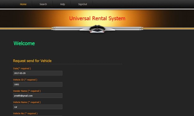
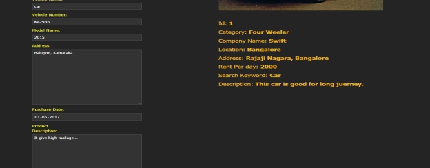
This is the user vehicle request page. User can request vehicle for rent which is uploaded by the vendor. Vehicle information can be automatically uploaded on the table which is already entered by vendor.
Admin View Vehicle Request
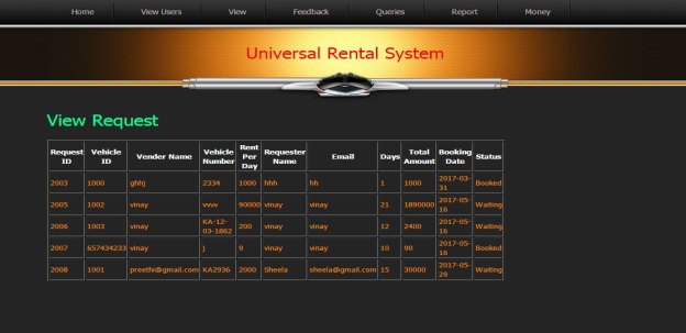
This is the admin view vehicle request page. Here admin can view the request which is send by the user.
Admin View Uploaded Vehicle
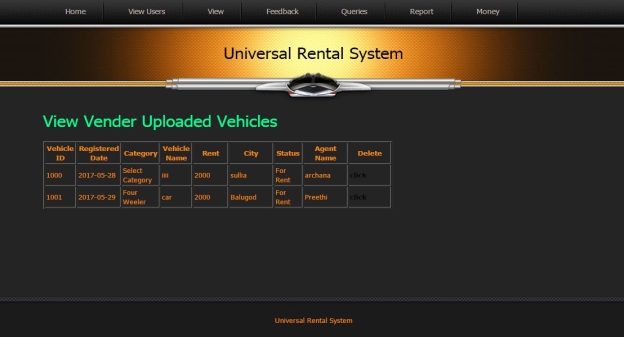
This is the admin view uploaded vehicle page. Admin can view the vehicle, which is uploaded by the vendor. He can also view or delete the information about vendor and vehicle.
User Query Page
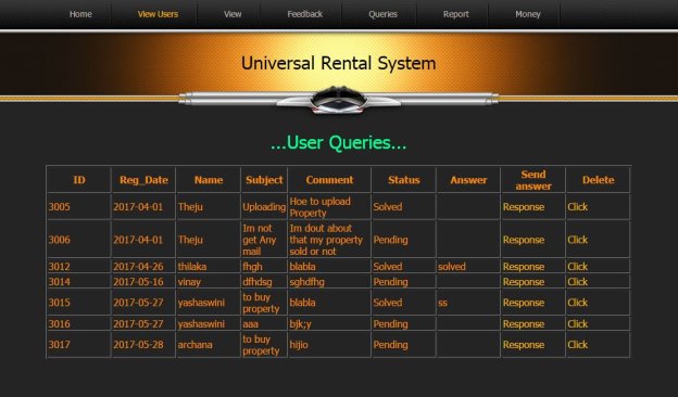
This is the view user query page. Here admin can view the queries which are send by the user and vendor. And admin can response for solving their query and update the status like solved.
Report based on Date
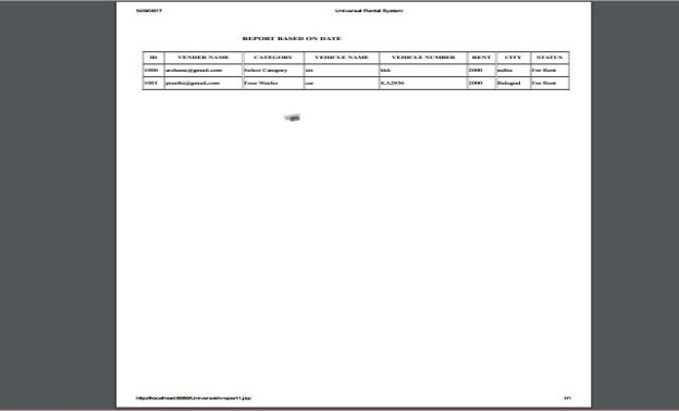
This is the report based on date. Here admin can view the report of the vendor based on date.
CHAPTER-7
SOFTWARE TESTING
7.1 INTRODUCTION
Software testing phase is the quality checking phase of the software system that is depended. In this phase, the software is checked for errors and the identified errors are then corrected.
Different types of testing are:
- Unit testing
- Integration testing
- Validation testing
- Output testing
Unit testing
Unit testing is testing method of software testing, where each single unit of the system is tested. Unit testing is done so that each module of the system works as it should be. In this universal rental system project there are basic modules. By giving different inputs we tested for each module.
Integration testing
In integration testing, the small units of system are integrated together and then tested. It is used to check whether all the units are integrated property and gives the appropriate results. In the rental system project integrated all the modules, and checked whether the integration affected the working of any other modules by giving different inputs.
Validation Testing
After the end of integration testing, the system is completely tested. To find the errors in validation testing, the system is tested to check whether the customer needs are satisfied.
Output Testing
After validation testing, the system should be tested to check whether the system produces output or not.
7.2 TEST CASES
Login page
| Sl.No | Test Case | Expected Result | Obtained Result | Remark |
| 1 | Enter the username, Password and click on login button | Display the home page of particular user | Display the home page of particular user | Successful |
| 2 | Click login button without entering username, password | Error message please enter the all the fields | Error message please enter the all the fields | Successful |
Vendor/Customer Registration Page
| Sl.No | Test Case | Expected Result | Obtained Result | Remark |
| 1 | By clicking register button after fill all the fields | Display, Successfully registered | Display Successfully registered | Success |
| 2 | Click on register button without enter any of the field | Display Please enter all the fields | Display please enter all the fields | Success |
| 3 | Click on register button by fill invalid Email format | Please enter the valid Email address | Please enter he valid Email address | Success |
| 4 | Click on register by Entering Character in phone number field | Display an error message “Numbers only” | Display an error message “Numbers only” | Success |
Admin Home Page
| Sl.No | Test Case | Expected Result | Obtained Result | Remark |
| 1 | By clicking view users button | Redirect to corresponding user page | Redirect to corresponding user page | Success |
| 2 | By clicking View Button | Redirect to corresponding Properties Page | Redirect to corresponding properties page | Success |
| 3 | By clicking Feedback Button | The page redirect to view customer feedback page | The page redirect to view customer feedback page | Success |
| 4 | By clicking Queries button | The page redirect to user queries page | The page redirect to user queries page | Success |
| 5 | By clicking Report button | The page redirect to corresponding properties report | The page redirect to corresponding properties report | Success |
| 6 | By clicking money button | Page redirect to website profit for corresponding properties | Page redirect to website profit for corresponding properties | Success |
Vendor Home Page
| Sl.No | Test Case | Expected Result | Obtained Result | Remark |
| 1 | By clicking Uploaded button | The page redirect to corresponding uploaded properties page | The page redirect to corresponding uploaded properties page | Success |
| 2 | By clicking Request button | It will goes to corresponding properties request page | It will goes to corresponding properties request page | Success |
| 3 | By Clicking feedback button | It will redirect to give feedback page | It will redirect to give feedback page | Success |
| 4 | By clicking Help Button | The page will redirect to ask for help page | The page will redirect to ask for help page | Success |
| 5 | By clicking money button | It will shows the website profit for corresponding properties | It will shows the website profit for corresponding properties | Success |
Upload Property Page
| Sl.No | Test Case | Expected Result | Obtained Result | Remark |
| 1 | Enter all the fields and then click upload button | Successfully uploaded your property | Successfully uploaded your property | Success |
| 2 | If any one of the field is not filled then click upload button | The error message shows like please fill up all field | The error message shows like please fill up all field | Success |
| 3 | In the field of price, filled with character then click upload button | Error message as invalid data type | Error message as invalid data type | Success |
User Help
| Sl.No | Test Case | Expected result | Obtained Result | Remark |
| 1 | Enter all the column and click submit button | Successfully sent your questions | Successfully sent your questions | Success |
| 2 | If any one of the field is empty then click submit | Message as please fill all the fields | Message as please fill all the fields | Success |
Feedback
| Sl.No | Test Case | Expected Result | Obtained Result | Remark |
| 1 | Enter all the fields and click submit | Successfully registered | Successfully registered | Success |
| 2 | If the subject and email field is not entered then click submit button | Error message all fields must required | Error message all fields must required | Success |
CHAPTER 8
CONCLUSION
The main aim of this developed project is to reduce the time consuming and also user friendly, where user can interact with system very easily. In this project there is no brokering system, where user can directly interact with vendors. This software provides fully functionality, which specified in software requirements.
In this developed project we are providing good communication between vendor and customer. And also this website can be accessed anywhere, any time through internet.
.
CHAPTER 9
FUTURE ENHANCEMENT
The application was developed to support future enhancement can be done with ease.
- Online transaction can be apply
- More properties can be added
- If any vendor, user signup our website, then his username and password send to his registered mobile number
- Any product update information will also send to his mobile
- Websites can be extended for to many cities
Appendix-A
BIBILIOGRAPHY
Books
- Ken Arnold, James Gosling, David Holmes, “JAVA Programing language”, 2003
- Patrick Naughton, Schildt Herbert, “C# 4.0 The Complete Reference”, Tata MC Graw-Hill, 2007.
- Pankaj Jalote, “An Integrated Approach to Software Engineering”, Third Edition
Websites
1. http://www.stackoverflow.com
2. http://www.wikipedia.org
3. http://msdn.microsoft.com
4. http://www.w3schools.com
Appendix-B
USER MANUAL
The Universal Rental system provides the services for three uses Admin, Customer, Vendor. The Admin is the system controller who has responsible for entire system.
Each user should follow the steps given below
Admin
Login
Admin can login by using username and password.
Home
The admin home page contains five options for view report, view user, view vendor, view or response feedback, view or response query.
View Report
The admin can view the properties report based on date.
View user and Vendor
The admin can view who are the user and vendor registered with our site.
Customer
Registration
The customer should click the user button for view the registration form. Then it contains several entries to fill up. After validate each field, then it is successfully registered.
Login
The Customer should login by using correct username and password, if the username and password miss match in the database then the system will not proceed to next page.
Customer home
If the customer enters correct username and password the system will redirect to customer home page. Here customer can view their request properties, search properties, help, give feedback, view generate report etc.
Request Properties
Here customer can request the properties what they want that is House, Vehicle, Machinery product.
Search Properties
Customer can search the properties based on their location, or agent name etc.
Help Page
Customer can ask any queries to the admin, and he can help them by solved their problems.
Give Feedback
Customer will give feedback about the system to the admin.
View Generate Report
Customer can view their report based date.
Vendor
Registration
The vendor should click the vendor button for view the registration form. Then it contains several entries to fill up. After validating each field, then it is successfully registered.
Login
The Vendor should login by using correct username and password, if the username and password miss match in the database then the system will not proceed to next page.
Upload Property
The Vendor can upload their properties on the site, anywhere in the city.
Request/Response property
The Vendor can request for any other property and also they got some response for the customer who requested his product.
Help Page
Customer can ask any queries to the admin, and he can help them by solved their problems
Give Feedback
Customer will give feedback about the system to the admin.
Cite This Work
To export a reference to this article please select a referencing stye below:
Related Services
View all


Related Content
All TagsContent relating to: "Information Systems"
Information Systems relates to systems that allow people and businesses to handle and use data in a multitude of ways. Information Systems can assist you in processing and filtering data, and can be used in many different environments.
Related Articles

DMCA / Removal Request
If you are the original writer of this dissertation and no longer wish to have your work published on the UKDiss.com website then please: