Performance Affecting Parameters of a 4-stroke Engine
Info: 12303 words (49 pages) Dissertation
Published: 19th Jan 2022
Tagged: Automotive
Abstract
Conventional Internal combustion engines are very inefficient at converting the energy contained within the fuel to Mechanical Energy. Only about 30% of the energy from the fuel you put into your petrol engine gets used to actually move your car. The rest of the energy is lost to engine and driveline inefficiencies.
With an ever-growing concern about the excessive reliance on the use of fossil fuels, and the damage the burning of these carbon-based fuels cause to the environment the investigation of methods of increasing engine efficiency has taken on an increased significance.
This project seeks to analyse and identify the main performance affecting parameters of a 4-stroke engine which is compliant with the Shell™ Eco-marathon competition Rules and Regulations. This project proposes to identify and purchase a suitable engine, and auxiliaries in order to allow for the investigation of the optimum parameters associated with the fuel efficiency of the engine with respect to fuel consumption and power output to ultimately improve the efficiency of the engine for future fitting within a prototype car which is compliant with Shell™ Eco-Marathon regulations.
The development of a test frame with the ability to measure, record and display findings in a clear manner will allow for continued development of increasingly fuel efficient engines.
Keywords: fuel efficiency, engine, Shell Eco Marathon, fossil fuel.
Contents
Click to expand Contents
1 Introduction
1.1 Literature Review
1.1.1 Shell™ Eco Marathon.
1.1.2 Summary of Shell™ Eco Marathon Engine Regulations
1.1.3 Review of reports and papers.
1.1.4 Honda GX35™ Technical Data
1.1.5 Honda GX25™ Technical Data
1.1.6 Honda™ GY6-139QMB Technical Data
1.2 Aims and Objectives
1.3 Summary of the Report Layout
2 Methods and Materials
2.1 Four Stoke Petrol Engine Components
2.1.1 Four Stroke Engine Performance Cycle
2.1.2 Carburettor.
2.2. Combustion Performance Variables.
2.2.1 Otto cycle
2.2.2 Combustion Chamber / compression Ratio.
2.2.3 Static / Dynamic compression Ratio
2.2.4 Fuel Delivery
2.2.5 Power Output
2.2.6 Stoichiometric Ratio and O2 sensor
2.3 Engine performance parameters, and requirements.
2.3.1. Brake Specific Fuel Consumption Calculation
2.3.2 Brake Mean Effective Pressure.
2.4 Electronic Fuel Injection System.
2.4.1 Engine Control Module (ECU).
2.4.2 EFI (Electronic Fuel Injection) Kit.
3 System Design & Modifications
3.1 Engine Alterations/ EFI Installation.
3.2 EFI System Initialisation / Testing / Troubleshooting.
3.3 Software Installation and Operation
4 Discussion
4.1 Limitations of Work
5 Future Work
5.1 Future Work
5.1.2 Compression ratio
5.1.3 Intake air Porting
5.1.4 Dual spark ignition
5.1.5 EcoEFI Small Engine Electronic Fuel Injection Tuning Guide.
5.2 Final Summary
6 References
7 Appendices
7.1 Appendix A Shell Eco Marathon Rules (Engine Section)
7.2 Appendix B Unleaded Petrol 95 Specification Data Sheet
Nomenclature
| Symbol | Description |
| kg | Kilogram |
| Km/h | Kilometres per hour |
| mph | Miles per hour |
| dB | decibel |
| m | metre |
| mm | millimetre |
| oC | Celsius |
| cc | Cubic centimetre |
| % | percent |
| rpm | Revolutions per minute |
| l/hr | Litres per hour |
| HP | Horsepower |
| kW | kilowatt |
| Nm | Newton metre |
| ηth | Thermal efficiency |
| TDC | Top dead centre |
| BDC | Bottom dead centre |
| γ | Specific heat |
| r | Compression ratio |
| P | Power (watts, kilowatts) |
| F | Force (Newtons) |
| m/s | Velocity, metres per second (V) |
| m | Mass (kilograms) |
| g | Gravity acceleration (m/s2) |
| Crr | Coefficient of rolling resistance |
| Cd | Coefficient of drag |
| ρ (rho) | Kg/m3 |
| CSA | Cross sectional area (m2) |
| BSFC | Brake specific fuel consumption (g/kWh) |
| FC | Fuel consumption (g/h) |
| T | Torque (Nm) |
| ω | Rotation (rads/s) |
| BMEP | Brake mean effective pressure (N/mm2) |
| ™ | Trademark |
| © | Copyright |
List of Figures
Figure 1.Honda™ GX35 four stroke petrol engine.
Figure 2.GX 35 technical specification
Figure 3.Honda™ GX25 four stroke petrol engine
Figure 4. GX25 technical specification
Figure 5 Honda GY6-QMB
Figure 6 Honda GY6 Specifications
Figure 7 Four stroke engine components
Figure 8. Four-Stroke Cycle
Figure 9. Otto Cycle
Figure 10. Unleaded petrol 95 Data Sheet Picture
Figure 11. Ecotrons EFI Kit
Figure 12: engine casing removal
Figure 13: Air filter and carburettor removal
Figure 14: Air filter fitted to new intake manifold
Figure 15: MAP sensor fitting
Figure 16. Fuel tank removal
Figure 17: Fuel tank modification and relocation.
Figure 18: Fuel pump locating and fitting.
Figure 19: Test frame and general arrangement.
Figure 20: Fuel line connection
Figure 21: Air intake sensor fitting
Figure 22: Hall sensor fitting.
Figure 23: O2 sensor fitting
Figure 24: Fitting the wiring harness.
Figure 25: Kill switch installation
Figure 26: ECU connected to harness.
Figure 27. EcoCAL Analysis software home screen.
Figure 28. Ecotrons Data Analyser Engine test Output Data
Figure 29 Output display with specific variable selection
Figure 30. 0 sec to 411 sec. GX35 engine test data.
Figure 31. 0secs to 411 secs. Data including spark timing
Figure 32: Air intake manifold.
Figure 33: Intake manifold section.
Figure 34. Single plug / Dual plug comparison
List of Tables
Table 1. Honda Engine Maintenance Schedule…………………………………8
Table 2. Concept Engine Specification…………………………………………10
Table 3. Honda Engine comparison table………………………………………16
List of equations
Equation 1. Thermal efficiency ……………………………………………………………20
Equation 2. Otto cycle efficiency ………………………………………………..23
Equation 3. Power output…………………………………………………………26
Equation 4. Velocity……………………………………………………………….27
Equation 5. BSFC…………………………………………………………………28
Equation 6. Engine power………………………………………………………..28
Equation 7. BMEP…………………………………………………………………31
Equation 8. Volumetric Efficiency……………………………………………….53
1 Introduction
According to a report published by the International Energy agency in 2007 the global demand for energy is predicted to increase by 55% up to 2030 in coincidence with the continued rise in world population. Oil is currently the most consumed form of fossil fuel for energy conversion, and accounts for the majority of energy production and consumption. However, the reserves of fossil fuels that can be used is also diminishing, making it increasingly difficult to meet the ever-growing energy demand.(OECD/IEA 2007)
The effects of global warming are anticipated to have potentially devastating consequences for our planet. Whilst changes have been observed in weather patterns, ice caps melting, water masses around the world increasing in both temperature and acidity, and animal migratory patterns. Up until relatively recently the causes, and indeed the existence of Global warming was a topic of debate and discussion. Today however the clear majority of researchers and scientists involved in this field agree that global warming is real and is primarily caused by human activity such as the burning of fossil fuels that release carbon dioxide (CO2) and other greenhouse gases into the atmosphere. (IPCC 2013)
One of the main factors affecting vehicle engine performance, and fuel efficiency, is power to weight ratio, simply put if you take an engine from a standard car capable of a top speed of 130 mph and put the same engine on a motorcycle you will have a substantially higher top speed. The difference being, the engine has less mass to move, a car that weighs less has less inertia to overcome, it has less mass to accelerate and to change direction.(Meriam &, Kraige 2013). Whilst the weight of the engine in this instance will be relatively insignificant efforts will be made to minimise weight where possible.
Shell™ Eco-marathon is a unique competition that challenges students around the world to design, build and drive the most energy-efficient car. With three annual events in Asia, Americas and Europe, student teams take to the track to see who goes further on the least amount of fuel.
The origins of the Shell™ Eco Marathon competition dates back to 1939 when two employees of Shell™ Oil Company in the USA made a bet over who could travel furthest using the same amount of fuel. Since then it has expanded to two further continents and incorporated many different classes of vehicle and fuel type. For the past thirty years teams of students have been given the opportunity to design, build and drive the most energy efficient car (Shell™ Global 2016).
Increasing fuel efficiency should allow us to decrease oil consumption without changing our driving habits. With this reduction in oil use carbon dioxide (CO2) emissions are reduced and furthermore the reduction guards against the impact of oil price volatility improving both environmental and economic security.
The fuel used by a vehicle at a given speed is determined by its technical characteristics, such as its weight, design (aerodynamically), engine cylinder volume and fuel type. A minimum fuel per time unit is needed to keep the engine running. In order to maintain a specific speed, air friction and the friction between the vehicle parts have to be considered, which will require additional fuel (Rouwendal 1995).
The total fuel per time unit can be thought of as:
Fuel required to keep engine running + additional fuel required to maintain required speed.
The choices made with regard to engine selection will be based on a review of current information available, including reports from participating teams, taking particular note of regulation changes.
This project proposes to explore and identify the optimum parameters associated with the fuel efficiency and power output of a four-stroke internal combustion engine, to specify a base engine, to investigate and identify alterations and ancillary systems required in order to allow for the production of a more efficient engine map for future fitting within a prototype car which is compliant with Shell™ Eco-Marathon regulations
1.1 Literature Review
The engine investigated as part of this project will be an internal combustion type engine powered by unleaded petrol, suitable for future installation within a prototype type vehicle.
The initial focus of the literature review will be on the rules governing engine parameters and specification to ensure compliance with the most recent rules and regulations. Past performance of teams and articles and reports relating to vehicle and component developments have been reviewed.
1.1.1 Shell™ Eco Marathon
The Shell™ Eco-marathon is divided into two categories, the Urban concept category, which is based on practical conventional car shaped design parameters, and the prototype category which is focused on maximum efficiency with driver comfort of little regard. The categories are further divided into fuel type; these are:
- Internal combustion
- Unleaded petrol
- Diesel
- Ethanol
- Gas to Liquid
- CNG (methane)
- Electric Mobility
- Hydrogen
- Battery Electric
The Shell™ Eco-Marathon regulations require that the petrol combustion engine used must operate on a four-stroke cycle to produce power output. Carburettors are prohibited from Shell Eco-Marathon and so there is a requirement to use a fuel injection system.
Other than this, and the requirement to run on fuel supplied by organisers, the design and type of engine is up to individual competitors. (Shell Global, 2016).
The Shell™ Eco Marathon regulations are subject to change from year to year and care should be taken to ensure most recent version are being considered.
With this in mind a review of the findings of previous Shell™ Eco Marathon entrants and others with regard to engine requirements and performance was undertaken.
1.1.2 Summary of Shell™ Eco Marathon Engine Regulations
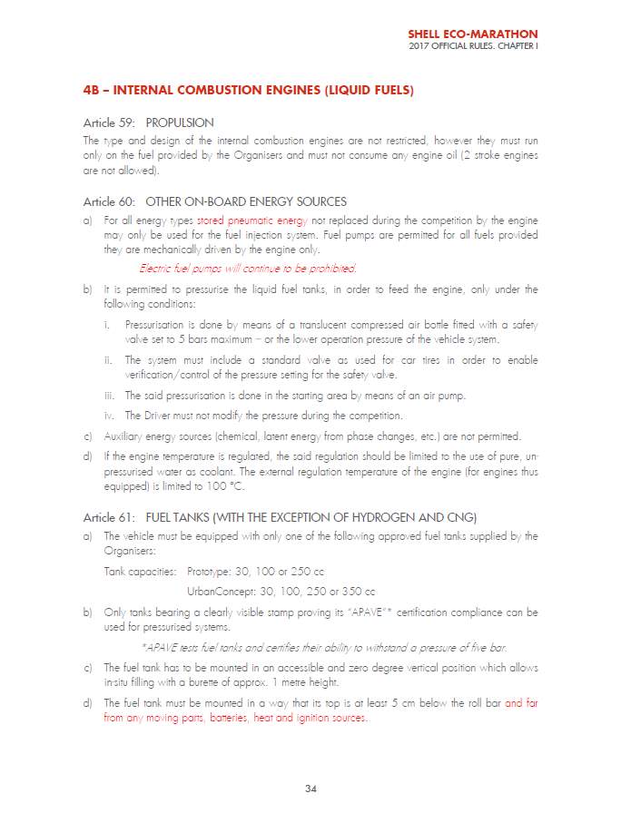
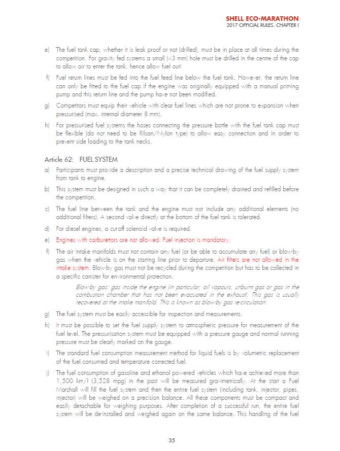
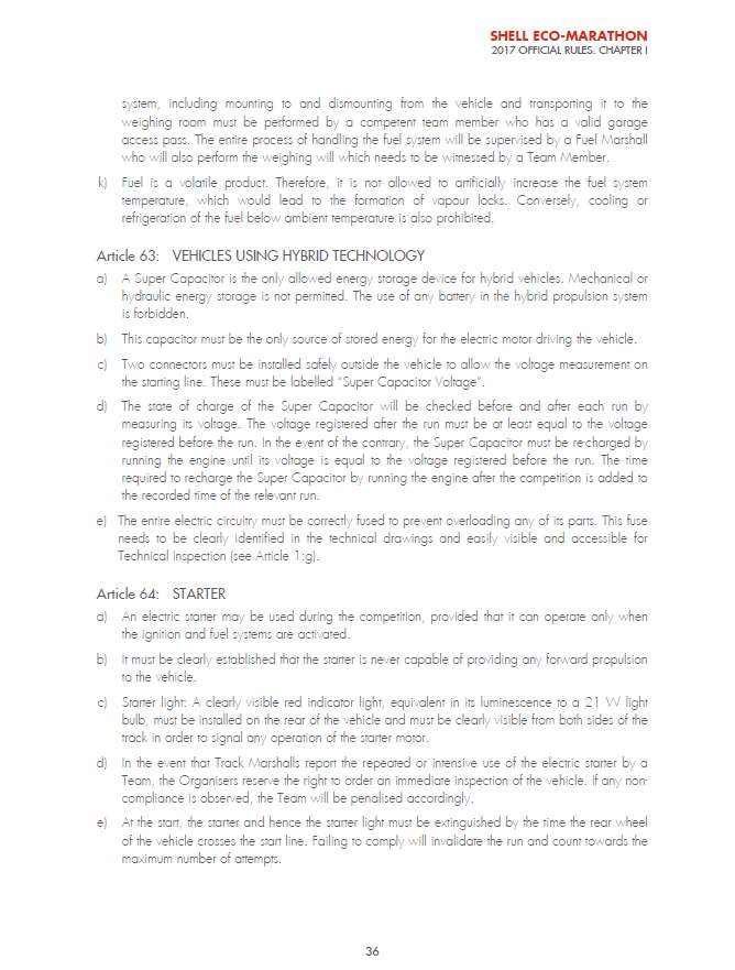
Within the Shell™ Eco-Marathon Regulations 2017 Official rules the section governing the internal combustion engine states that the type and design of the ICE are not restricted, however they must not consume any engine oil, thus excluding two stroke engines.
- Pressurisation of the fuel tank is permitted subject to compliance with safety procedures and regulations.
- Any auxiliary energy source is prohibited.
- The vehicle must be fitted with fuel tank supplied by organisers and must be mounted and oriented as per the organisers specification.
- Fuel lines must be clear and pressurised fuel systems must have flexible connection hoses.
- Engines with carburettors are prohibited. Fuel injection is mandatory.
- During competition cars must maintain an average speed of at least 15mph (23km/h) measured over a distance of 10 miles.
The Shell™ Eco Marathon regulations pertaining to engine selection and parameters are attached (Appendix A).
The design specification for the engine modifications should begin with the restrictions placed on design by the requirement for compliance with the Shell™ Eco-marathon Rules & Regulations. The most current version of these rules will be used as a basis for compilation of the requirements and restriction. A full set of current rules is available at:
Whilst this summary governs all aspects of engine specification within many criteria there is scope for refinement and improvement.
- Performance
- The engine will use a four-stroke cycle
- The engine will be fuelled by Shell™ FuelSave Unleaded 95 (Europe and Asia)
- The engine will be fitted with ‘dead man switch’
- The engine will have no carburettor and will be fuel injected
- The engine will have clutch system fitted
- Engine sound level will not exceed 90 dB @ 4m
- The engine will not consume any engine oil
- Environment
- The engine will be enclosed in body of vehicle and used in European weather conditions.
- Temperature range -5 to +30 C ambient air temp
- Noise should not exceed 90 dB @ 4m
- Maintenance
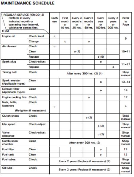
Table 1. maintenance Schedule Honda™Motor Co.Ltd 2014
- Engine to be maintained as per manufacturer’s instructions (Table 1.1)
- Service intervals should be increased if exposed to dusty environment
- Safety
- Engine will be fitted with a ‘dead man’s switch’ to disengage propulsive power in the event of emergency
- An external and internal emergency shutdown mechanism will be fitted.
- Engine noise will not exceed 90 dBA @ 4m
- Engine exhaust contains poisonous Carbon Monoxide. Ensure adequate exhaust provision.
- Engine and exhaust become very hot during operation. Ensure flammable materials are kept away.
- The fuel tank feeding engine must be supplied by Shell Eco Marathon organisers and have a capacity of 30, 100 or 250 cc. (This is not a requirement for development).
- Size and weight restriction
- Consideration will be given to ensure engine fits within required space envelope of car body.
- Weight of engine will be considered to maximise weight to power ratio.
As stated previously (performance 1.1.4) carburettors are prohibited from Shell™ Eco-Marathon vehicles and so an alternative fuel delivery system must be installed. It is proposed to install a pumped injected fuel system in accordance with regulations. Investigations will be made into how best to achieve optimum control over fuel delivery to ensure maximum possible efficiency.
1.1.3 Review of reports and papers
In a report from Adeniyi et al.(2012) undertook the design of an engine for the Shell Eco Marathon which they planned to manufacture to the specifications as shown in table 2. Above;
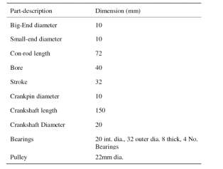
Table 2. Concept Engine Specifications (Adeniyi&Mohammed 2012)
They presented a proposed design that with this specification a fuel economy of 3000 miles per gallon (1275.43 km/litre) may be achievable. This involved the manufacture of a bespoke engine and to date their work is incomplete.
In a report carried out to determine the relative performance and suitability of engines (Mengistu 2011) carried out testing on a number of small internal combustion engines. His objectives included the testing and comparison of two small engines to determine efficiency. A Dynamometer was used to compare performance characteristics of each engine. The engines tested included the Honda GX35™ (35cc) and a Fuji IMVAC™ (24cc). It was concluded that the Honda GX35™ outperformed the Fuji based on cost, mass, volume, reliability and ease of starting and found that during testing at 60% throttle the Honda™ engine was outperforming manufacturers performance maps.
A report carried out by a group from Florida International University (Acosta et al. 2012) reviewed a range of competitors in the previous year’s competition. They found that in spite of a disparity in funding there was a similarity in size and type of engine used. Of the entrants who revealed their engine detailed the engine capacity ranged from 34cc to 57cc and all had incorporated some form of engine management system.
In April 2012 Akinola et al. investigated car driving style and miles per Gallon. They carried out computer simulations on a number of four stroke engines ranging from 25 cc to 196cc. They concluded that fuel economy is increased by switching off engine and coasting rather than idling throughout. The simulations carried out showed the best fuel economy was achieved by a 57cc engine (Akinnola et al. 2012).
In a report published by N. Arizona University a number of students carried out a comparative study of 3 Honda engines to determine their relative merits. The three engines compared were the Honda GY6™ 50cc, Honda GX25™ 25cc and the Honda GX35™ 35cc. they concluded that the Gy6 was most suitable for their specific requirements due to the integrated clutch and starter.
Following the review of previous literature and reports from previous entrants it is clear that the Honda™ range of small engine been selected by many teams and following some minor modifications initial assessment suggest they fall within the required parameters. (Mengistu. 2011) (Akinnola,Ghaniyu, Mohammed 2012).
1.1.4 Honda GX35™ Technical Data
According to the manufacturer’s literature, the Gx35 is one of a series of the world’s first 360° inclinable 4-stroke engines. It is commonly used in garden equipment, water pumps and within agricultural environments (Honda™ Motor Co. Inc. 2017).
The Honda GX35™, pictured below, is 204mm(l) x 234mm(w) x 23mm(h), it has a dry mass of 3.3kg, 35.8cm3 displacement, a fuel consumption rate @7000rpm of 0.71l/hr a power output of 1.3 HP (1.0 k W) @ 7000 rpm and a max. net torque of 1.6 Nm @ 5,500 rpm as illustrated in the performance curves and technical specifications shown in Fig1. & 2. below
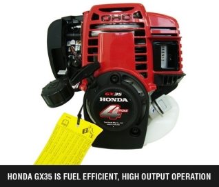
Figure 1.Honda™ GX35 four stroke petrol engine. (Source: Honda Motor Co. Ltd. ©2017)
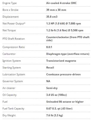
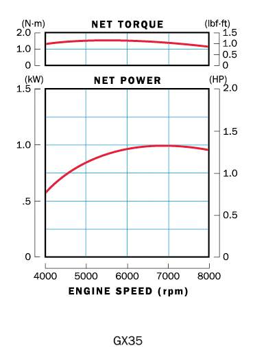
Figure 2. GX 35 technical specification (Source: Honda Motor Co. Ltd. ©2017)
1.1.5 Honda GX25™ Technical Data
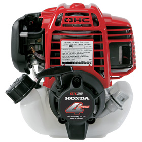
Figure 3. Honda™ GX25 four stroke petrol engine Source: Honda Motor Co. Ltd. ©2017
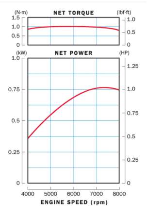
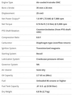
Figure 4. GX25 technical specification Source: Honda Motor Co. Ltd. ©2017
1.1.6 Honda™ GY6-139QMB Technical Data
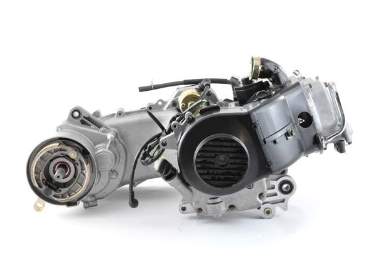
Figure 5 Honda GY6-QMB (Source: Honda Motor Co. Ltd. ©2017)
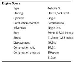
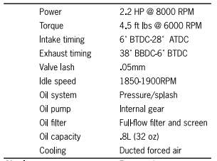
Figure 6 Honda GY6 Specifications (Source: Honda Motor Co. Ltd. ©2017)
The GY6- QMB is a moped engine and comes complete with CVT clutch and electric starter. This system represents a much more ‘plug and play’ installation. Considering the dry weight of the engine and the associated complexity of the integrated systems while this may be an appropriate choice for future work. It is deemed unsuitable for the work proposed in this study.
As the Honda™ engines have been successfully integrated into many previous Eco-Marathon vehicles it seems sensible to gravitate towards this range. The relative specifications are detailed in table 3. below;
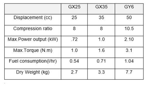
Table 3. Honda™ Engine specification Comparison.
1.2 Aims and Objectives
1.2.1 Aims
The aim of this project is to select an appropriate baseline 4 stroke engine, to design, and develop modifications to create an ultra-high efficiency system, compliant with current Shell™ Eco- marathon Rules, for future installation into a prototype vehicle for entry into the Shell™ Eco- Marathon.
1.2.2 Objectives
- To critically review literature concerning micro efficiency engine development and other relevant literature
- To select an appropriate base engine and fuel injection system.
- To develop a test regime to measure, record and display output parameters
- To collect data recorded as a result of test calculations
- To select most appropriate parameters to optimise performance
1.3 Summary of the Report Layout
A background section undertaken to give a practical understanding of the internal combustion engine process will be detailed in Chapter 2. Methods and Materials. The modification process and alterations to the baseline engine will be documented including the calibration of ancillaries to maximise performance. The factors affecting engine performance will be identified allowing theoretical efficiencies to be calculated.
Chapter 3. will detail the outcome of the engine alterations. The fitting and debugging of the EFI installation will be discussed. In order to validate theoretical results outputs from testing will be illustrated in graphical form and as necessary to best illustrate performance trends. The software installation will also be discussed.
Chapters 4 & 5 will add evaluation to the installation and move towards explaining modifications in order to facilitate repeatability. Recommendations will be made regarding physical modifications which may further improve engine efficiency. Future work will be identified with recommendations as to further system improvements. With the final summary recapping the process.
2 Methods and Materials
2.1 Four Stoke Petrol Engine Components
Figure 1, below identifies the components within the engine. The piston (F) is connected to the crankshaft (H) by the conrod (J) converting the linear motion of the piston to a rotational motion.
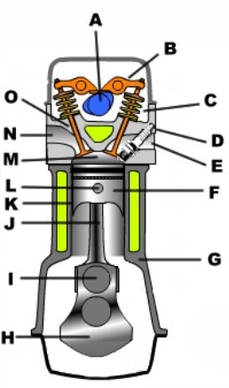
A. Camshaft
B. Tappet
C. Valve spring
D. Spark plug
E. Exhaust
F. Piston
G. Crankcase
H. Crankshaft
I. Big end
J. Conrod
K Cylinder
L. Gudeon pin ( secured with circlip)
M. Combustion chamber
N. Inlet
O. Valve
Figure 7 Four stroke engine components (http://kvtech.4t.com/4Stroke/how_engine_four.ht)
From thermodynamics, thermal efficiency (ἠth) is a measure of the performance of any device which uses thermal energy. The efficiency is simply a ratio of useful output and the initial input. The input (Qin) is the heat available from the input fuel used with the output being the mechanical work (Wout). A general illustration of thermal efficiency is given by:
And γ is the specific heat ratio
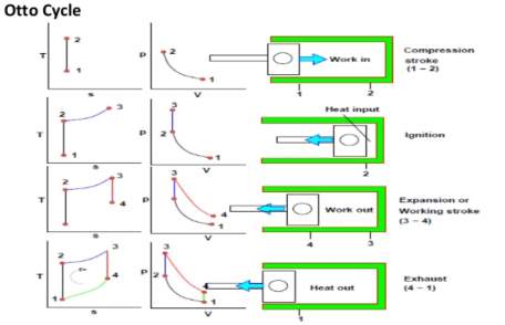
Figure 9. Otto Cycle graphical representation. Source: www.grc.nasa.gov
Figure 9. above shows a breakdown of the Otto cycle. The diagrams represent T-s (Temperature-Entropy) and p-V (pressure-Volume) with respect to the engine combustion cycle. Starting at the top from 1 – 2(work in) the air and fuel are introduced into engine and compressed. Temperature increases, volume decreases, pressure increases. (Everett et al. 2003)
At 2 ignition takes place. Temperature increases, entropy increases, pressure increases.
From 3 – 4 (work out) Temperature decreases, pressure decreases, volume increases.
From 4 – 1 (exhaust) Enthalpy decreases, pressure decreases slightly.
The area enclosed by the diagrams represent the work done by the process.
This represents the ideal Otto cycle and does not take into account any heat leaving the system or for any frictional losses with combustion being instantaneous. In reality the ideal cycle does not occur however the shape of the diagrams would be similar but the area would be smaller representing the system losses. (Everett et al. 2003)
2.2.2 Combustion Chamber / compression Ratio
The combustion chamber is the void within the cylinder where compression and combustion occur. As the piston reciprocates, the area within the combustion chamber alters. The difference between the largest and smallest area is called the displacement, which is measured in Cubic centimetres (CC). The displacement is related to the power output of the engine. The higher the displacement the higher the power as more of the combustible air/fuel mixture can be held and ignited. The ratio between the volumes when the piston is at (BDC) compared to when it is at (TDC) is known as the compression ratio. The higher the ratio, the higher the compression within the cylinder leading to increased fuel efficiency due to a more powerful explosion from the fuel and air within cylinder (Heywood. 1988).
The compression ratio of an engine is specific to the design of the particular engine with higher values increasing the engines efficiency. With an increase in compression ratio, as the molecules of air fuel mixture are in closer proximity, comes an increase in power caused by the more rapid combustion process. The efficiency of an Otto cycle engine increases with an increase in compression ratio. The maximum compression ratio has a limiting factor, a side effect of excessive compression is an engine phenomenon known as knock. Knock occurs due to the premature combustion of fuel within the cylinder caused by excessive pressure and thus excessive temperature igniting pockets of fuel independently of spark ignition. This causes excessively high pressure areas within the cylinder as well as shock waves leading to a reduction in efficiency and the possibility of component damage (Heywood. 1988).
2.2.3 Static / Dynamic compression Ratio
Static compression ratio is defined as the compression measured in an engine cylinder when the intake valve is completely closed. This situation rarely occurs in reality however, as the engine runs at such a high RPM the intake valve opens before the piston has completed its stroke. This causes a pressure reduction in the cylinder causing a drop in efficiency. Dynamic compression ratios take this situation into account. The engine tuning can be altered to close the intake valve earlier in cycle building pressure or vice versa (Heywood. 1988).
2.2.4 Fuel Delivery
A Fuel injection system is currently mandatory within the Shell Eco-Marathon rules. As fuel injection affords superior control over fuel usage as reported by G. Karthikeyan et al. (2013) this would be the fuel delivery method of choice within Shell™ Eco-Marathon vehicles. There are two main types of fuel injection Direct Injection – where fuel is supplied to the combustion chamber and Indirect injection – where the fuel is supplied via a secondary chamber. (Karthikeyan, Ramajayam, Pannirselvam. 2013).
2.2.5 Power Output
The maximum power produced by an engine is limited by the quantity of air consumed. The power generated by the engine is governed by the volumetric capacity, volumetric efficiency, fuel/air ratio, quality of fuel, and rev. per minute (RPM). The maximum rotational speed is restricted by material properties and the performance of lubricating oil. Tian et al 2002 reported that as engine speed is increased component breakage is a possibility and a phenomenon known as piston ring flutter where, with changes in radial forces, vibration of the piston ring can occur within the piston grooves (Tian. 2002). This phenomenon can result in a loss of cylinder pressure.
2.2.6 Stoichiometric Ratio and O2 sensor
The engine fuel supply mechanism, whether carburettor or fuel injection, mixes air with fuel in the correct quantities in order to maintain efficient combustion.
The Stoichiometric ratio is defined as the perfect mix of mass of air and fuel where there is exactly the correct proportion of air supplied to allow complete combustion of fuel. The typical stoichiometric ratio, for a petrol engine, is 14.7 air to 1 of fuel, measured by mass (McAllister, S.2011).This ideal ratio is known as the stoichiometric ratio or alternatively Lambda (λ) 1. A mixture with an excess of fuel is considered rich and would have a value 1. The ability to maintain a ratio as near stoichiometric as possible will help to improve power output and fuel economy. As the engine parameters are constantly adjusting, the ideal ratio is impossible to maintain. The relationship between the MAP sensor on the air input and the O2 sensor (lambda sensor) on the output are used by fuel injection systems to constantly monitor changes in intake and exhaust gas composition and this feedback is used by the ECU to modify fuel supply and other variables to endeavour to maintain fuel efficiency.
2.3 Engine performance parameters, and requirements
The determination of an appropriate engine requires an initial analysis of the specific demands and requirements.
The power output requirement for any vehicle for a given speed is a function of the forces opposing vehicle motion and the vehicles velocity:
g = gravity acceleration
Crr = coefficient of rolling resistance
ρ = air density (dependant on altitude above sea level)
Cd = coefficient of drag of the vehicle
A = maximum C.S.A.of the vehicle perpendicular to direction of travel.
The Power (watts) used by the vehicle is the product of the power necessary to overcome the resistance forces multiplied by the length of operation time adding the energy required to attain the required speed.
P=12mv2+Pt
(6)
For the purposes of this report the engine power analyis will end at the drive shaft connection. This will avoid the need for any assumptions regarding frictional losses, aerodynamics and drive train losses assuming a drive train efficiency of 100%.
2.3.1. Brake Specific Fuel Consumption Calculation
To establish the optimal operating parameters of the engine with respect to fuel consumption the specific fuel consumption or Brake Specific Fuel Consumption need to be established. Practically BSFC measures the efficiency with which the fuel is being converted into a given power.In other words it is a measurement of the efficiency of the combustion process.
The BSFC is calculated using the equation below:
BFSC= FCP (7)
Where:
BSFC = Brake Specific fuel consumption
gkWh
FC = Fuel consumption rate
gh
P = power from engine kW
The power from the engine can be found using;
P=Tω (8)
Where T = Torque developed by engine Nm
ω = rotation of engine
radss
From the performance specifications provided by Honda we know the following:
Brake Power = 1.0kW (1.3 HP) @ 7000rpm
Max. Torque = 1.6 Nm @ 5500rpm
Bore = 39mm
C.S.A. of cylinder = 1194.59mm2 (0.0012m2)
Stroke = 30mm (0.03m)
Fuel consumption = 0.71l/hr @ 7000 rpm
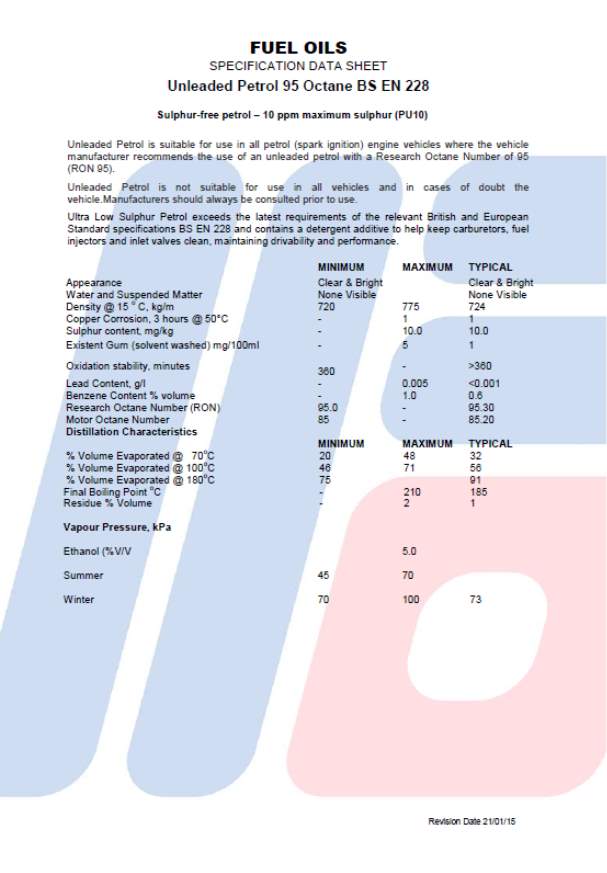
The excerpt from the fuel specification data sheets in fig. 10. below gives the typical range of fuel density of unleaded petrol 95 (Fuel Oils UK 2017).
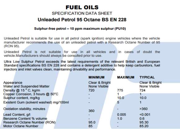
Figure 10. Unleaded petrol 95 Data Sheet Picture source: http://www.fueloils.co.uk
Allowing us to calculate the off the shelf BSCF of the Honda GX35™;
The typical density of unleaded petrol 95 is given as 724kg/m3 which is equivalent to 0.74kg/litre (740g/litre).
Therefore, as the fuel consumption of the engine is 0.71 litres/ hour @7000 rpm the mass of the fuel consumed in 1 hr, or fuel consumption rate, is;
0.74kg1kg×0.71 =0.525 kg/hour
The Honda™ specification sheet tells us the power output @ 7000 rpm is 1kW so the BSFC is;
.525kg/hour1 kWh=525g /kWh
This is equivalent to;
525g60=8.75g/minute
Or;
8.75g60=0.14g/second
For the Honda GX 25™ this figure is
9g60=0.15g/second
For the Honda™ GY6 it is
8.5g60=0.14g/second
2.3.2 Brake Mean Effective Pressure
Brake mean effective pressure is a calculation of the average pressure which if applied on the pistons in a uniform manner for the entire duration of each power stroke, would produce the measured brake power output (EPI Inc. 2011). This figure allows for the comparison of engine performances between engines of a similar type.
BMEP = Brake Power ×60000stroke ×C.S.A. ×RPM (9)
Where
BMEP = brake mean effective pressure
Nmm2
So for the GX35
BMEP=1000w×60000 30 mm×1194.59 mm2×7000
Giving
BMEP=0.239Nmm2or 2.39 Bar
For the GX25
BMEP=0.246Nmm2or 2.46 Bar
And for the GY6
BMEP=0.355Nmm2or 3.55 Bar
These figures relate to the off the shelf unmodified carburetted engines and can be used as a datum to benchmark alterations in performance as the engine requirements evolve.
Whilst the performance of the GY6 engine is superior the size and complexity of system incorporating starter, clutch and transmission add a lot of weight and minimise the adaptability of the engine and having reviewed the available literature regarding the three engines. It is decided to proceed with Honda GX35™ as the base engine for development.
2.4 Electronic Fuel Injection System
Electronic fuel injection systems work by drawing fuel from the fuel tank with a fuel pump which pressurises the system. Fuel pressure is regulated by inline sensors which ensure the flow is adjusted according to demand. Excess fuel is returned to the tank during low demand such as idling operations. The fuel is sprayed under pressure through an intake manifold. The air volume supplied to the engine is precisely controlled by means of a butterfly type valve. Air flow is usually measured by either a Mass airflow(MAF) sensor or speed density using a Manifold Absolute Pressure sensor(MAP). Both arrangements do the same thing but in a different way. A MAF system is considered more responsive as it measures the air using the MAF sensor and carries out tuning operations based on signals received. If the throttle is fully open the system reduces calculations going into a closed loop operation and relying on fewer input signals. The MAP system does not measure air but relies on a manifold absolute pressure (MAP) sensor to supply altitude and air temperature that is then used to calculate air mass. Whichever system is used most EFI systems measure and respond to much the same inputs and signals by some means or other (AA1Car 2017).
These consist of;
RPM
Rpm is measured using a Hall sensor or other form of magnetic pick up sensor. As rpm increases the number of injection pulses increases in tandem.
Airflow
As throttle demand and rpm increases air flow will increase to maintain best possible air fuel ratio.
Manifold pressure / throttle position
As the throttle demand increases the manifold pressure increases. This will require an increase in fuel supply.
O2 Sensor
By measuring O2 content the system can regulate the air/fuel mixture for optimum combustion and make necessary adjustments.
Air Temperature
Through a sensor mounted in the air filter or at the intake manifold the air intake temperature is monitored. The density of air decreases as the temperature rises. Less dense air needs less fuel. The ECU increases or reduces the fuel pulse width to allow for density changes. The air temperature sensor is less critical in a mass airflow systems as the air flow meter is measuring air intake mass.
Electronic fuel injection systems will almost certainly achieve a reduction in fuel consumption. With no added tuning a reduction of 30% is not unreasonable according to UAV Engine Systems (Power4Flight2017), a company specialising in the integration of EFI systems. This reduction is achieved by the constant feedback from the monitoring control circuitry which reacts to changes in input signal to alter fuel delivery and air supply in an attempt to maintain optimum performance. Carburettor based systems tend to be inefficient at extremes of output both low and high as the carburettor cannot be optimised for a variance in performance requirement. This means that a performance compromise must be made.
2.4.1 Engine Control Module (ECU)
The ECU is an essential part of an electronic fuel injection system. These units act like the ‘brain’ of the engine, in that they interpret signals received from the various sensors and alter the engine performance parameters accordingly to maintain operating efficiency. These units can control a variety of variables within the engine including;
Air / Fuel ratio
The ECU can regulate the amount of fuel required based on feedback from engine sensors ensuring optimum air to fuel mix. Throttle sensors relay how much throttle is pressed whilst a mass air flow sensor, or manifold absolute pressure feeds back information which allows the ECU to alter fuel delivery to maintain optimum air fuel ratio.
Ignition Timing
The exact timing of the ignition spark can be adjusted to maintain maximum performance. This can help eliminate engine knock by preventing premature ignition prior to the compression stroke.
Variable valve timing
The ECU can also control the engine cycle when the engine valves open. As engine speed increases the valves open sooner. This optimises the air flow into the cylinder which can result in an increase in power and fuel economy.
The throttle position and MAP sensors relay information to the ECU where this feedback is used to vary the amount of fuel to supply to keep the mixture stoichiometric. O2 sensors monitor oxygen content in exhaust gases to ensure efficient combustion. The feedback from these sensors allows the fuel feed to be fine-tuned to further improve efficiency.
As previously stated the Shell™ Eco-Marathon regulations require a fuel injection system to be used. There are a number of companies such as Megasquirt™ and Ecotrons who supply electronic fuel injection kits which have been used by Shell eco marathon teams in the past. Ecotrons have developed a system specifically geared towards engines in the size category of the GX35. The Ecotrons supplied GX35 Engine fuel Injection kit is very popular amongst teams competing in Shell™ Eco Marathon and will be purchased to facilitate the replacement of the existing carburettor in order to allow precise control of engine variables. This will allow for the development and alterations to the stock engine without having to size and source all the individual components. However, the electric fuel pump supplied with kit is not permitted according to current rules. (Shell Global 2016 p.35). For competition the pump would be replace with a pre pressurised fuel delivery system. Many teams have previously used plastic soft drinks bottles fitted with a Schrader valve, a type of pneumatic tyre valve, to pressurise system.
2.4.2 EFI (Electronic Fuel Injection) Kit
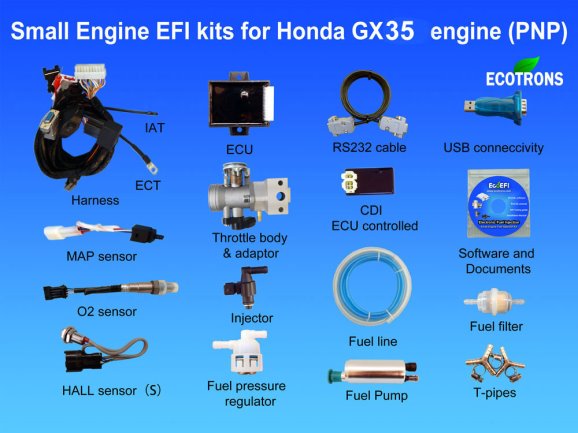
Figure 11. Ecotrons EFI Kit source: http://www.ecotrons.com/products/honda_gx35_engine_fuel_injection_kit/
Ecotrons claim that their SE -EFI fuel injection kits are small, light and easy to install. They have developed a kit specifically for the Honda GX35™ which includes a throttle body adaptor which allows the new throttle body to be bolted directly to engine. The kit also includes a bracket to allow the Hall sensor to be fixed to the engine block. The kit controls both fuel delivery and spark timing. The kit reuses the flywheel to provide a timing input for the ECU allowing the ECU to fire injectors and coil. Ecotrons (2017).
The fuel injection system includes all the items as shown in Figure 6. above.
The major components include;
- Wiring Harness
- TempertureSensors
- Fuel pump assembly
- O2 sensor
- Engine control Unit (ECU)
- Throttle Body c/w intake manifold
- Fuel Injector
- Hall Sensor
- MAP Sensor
3 System Design & Modifications
3.1 Engine Alterations/ EFI Installation
The Honda™ GX35 engine is designed for use with garden equipment, such as strimmer’s, cultivators and general agricultural equipment. As such the engine body is protected by moulded casing.
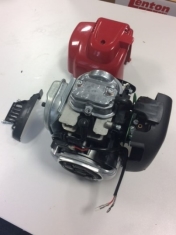
Figure 12: engine casing removal
The first stage in the engine alteration involved the removal of all external coverings. This allowed access to components and fixings. (fig.12)
1. The air filter and carburettor can then be easily removed by disconnecting the 2 No. Allen screws (fig.13)
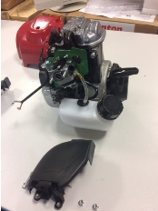
Figure 13: Air filter and carburettor removal
2. The existing screws can be used to fit the new throttle body but need to be reduced in length by 10mm. The new intake manifold can be fitted.
3. A 35mm air filter is fitted to throttle body. (fig.14)
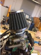
Figure 14: Air filter fitted to new intake manifold
4. The MAP sensor is installed into connection at intake manifold on throttle body. (Care should be taken to ensure sensor is protected from hot engine) (fig.15).
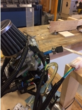
Figure 15: MAP sensor fitting
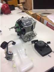
Figure 16. Fuel tank removal
5. The fuel tank was removed from its position at underside of engine by removing 3 No. fixing screws. (Fig.16).
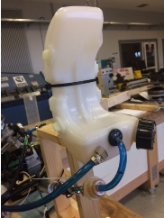
Figure 17: Fuel tank modification and relocation.
6. In order to accommodate the return fuel line a 5.5 mm hole was drilled into existing tank and a fuel tank adaptor was fitted and sealed. The tank was inspected to ensure it was leak free and free from any debris from the drilling process. (Fig.17).
7. The next stage was to install the fuel pump. This was fitted between the fuel tank and throttle body. Care was taken to ensure it was not bumped or dropped. The fuel pump must be installed in a position where it is lower than the lowest point of the tank. (Fig.18)
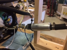
Figure 18: Fuel pump locating and fitting.
8. To accommodate the relocated fuel tank, and mount the engine, a test frame was fabricated. The engine was connected and the fuel tank positioned as shown in figure19 below. This allowed for the fuel pump to be located below tank, as required.
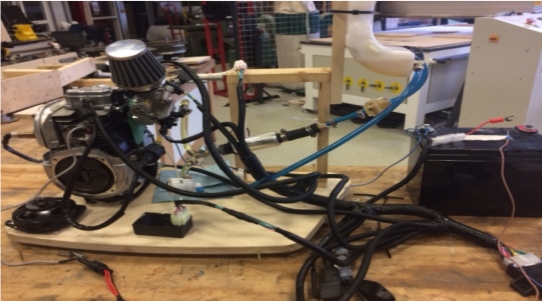
Figure 19: Test frame and general arrangement.
9. The fuel lines were then connected from tank connection, to fuel filter, to fuel pump inlet and secured using 10-16mm jubilee clips©. (Fig.20)
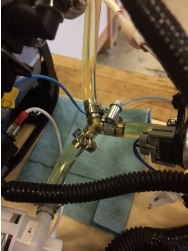
Figure 20: Fuel line connection
10. The high-pressure fuel line was fitted from pump outlet to the fuel injector.(Fig.20)
11. Return fuel line was connected using tee connector.(Fig.20)
12. The air intake sensor was installed with a suitable hole drilled into air filter. Sensor inserted and sealed with suitable sealant. (Fig.21)
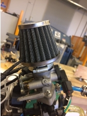
Figure 21: Air intake sensor fitting
13. The engine temperature sensor was fitted to the cylinder head.
14. The factory fitted ignition coil was removed and the Hall sensor was installed using the same fixing holes. On the flywheel, there are two magnets 1 no. N-pole magnet and 1 No. S-pole magnet. These are clearly marked with N and S on face of flywheel. The supplied Hall sensor is south pole magnet triggered and must be aligned as shown in installation documentation. The alignment can be checked on powering up system as the sensor has an LED light which illuminates when activated. (Fig.22).
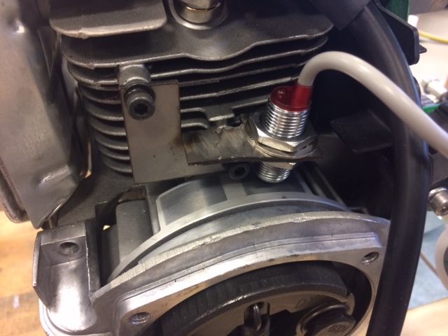
Figure 22: Hall sensor fitting.
14. The CDI and coil were then installed using a fixing point directly on to body of engine.
15. Fitting the O2 sensor to the exhaust required comparatively a lot of alteration with the requirement to drill a 15-mm hole into exhaust port, weld on a mounting bung and then fit O2 sensor.(Fig.23).
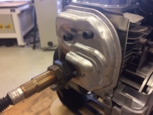
Figure 23: O2 sensor fitting
16. A 12V battery is required to power system. It is important that battery negative is connected to chassis.
17. At this stage, the wiring harness was used to connect the various sensors (Fig24.) All components were clearly labelled and the snap fitting male and female connections were specific to each other. This made the connection process very straight forward.

Figure 24: Fitting the wiring harness.
18. A switch must be installed to act as a kill switch to turn engine off. This switch acts as the ECU power on signal. The ECU will not operate without this connection. The switch wire on the harness is marked KEYSW and is pink in colour. This cable is connected through 5A rated switch and connected to 12V+.

Figure 25: Kill switch installation
19. It is noted that the only wire that connects to 12V+ other than the switch wire is the red 12V+ wire. Incorrect connection can lead to ECU damage.
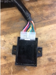
Figure 26: ECU connected to harness.
After a final check of all connections the EFI system installation is complete.
3.2 EFI System Initialisation / Testing / Troubleshooting
Check all connections and fuel lines, an initial test can be carried out on the system.
When the key switch is turned on the fuel pump should activate for a few seconds. If this does not happen recheck connections, and retry.
When the fuel pump can be heard running switch key switch to off and fill fuel tank with petrol.
The key switch can be switch on and off a number of times to rid the fuel lines of air bubbles. This can be observed as fuel lines are transparent. It may be necessary to purge system by disconnecting fuel connecting line put end into collection vessel and run pump until fuel comes through line.
On initial start up the engine can run roughly. This may be due to small pockets of air remaining air in the system and if the engine is left to warm up it may correct.
After the engine has stabilised the engine can be operated at different throttle rates in order to allow the ECU to adapt to inputs.
3.3 Software Installation and Operation
At this stage, the control software EcoCAL©, which is included in the EFI package, should be installed on a P.C.
The computer should be connected to the serial output cable from the harness using the serial cable, or USB adaptor, if required.
Once connected a screen like the one shown in Fig. 27 below will be displayed. (Note the green connection confirmation in the bottom corner of screen.
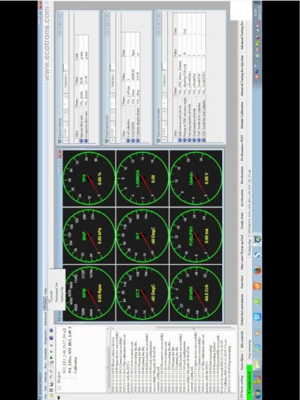
Figure 27. EcoCAL Analysis software home screen.
The EcoCAL© software can be used to log the data outputted from the ECU and recorded onto the P.C. for review. Figure 28. below shows the output of a 10-minute engine test. The EcoCAL© software, by default, displays all variables. As you select a particular parameter the associated plotted line is highlighted allowing for clearer examination. Alternatively, the user can select only the variables of interest as shown in (fig.29) below.
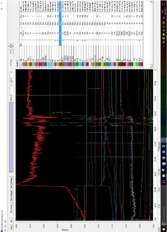
Figure 28. Ecotrons Data Analyser GX35 Engine test Output Data.
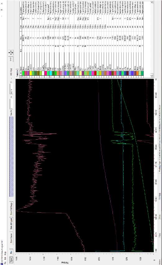
Figure 29 Output display with specific variable selection
The variables chosen for display were;
1. Engine speed (rpm)
2. Throttle position (%)
3. Manifold absolute pressure (kpa)
4. Oxygen sensor voltage (V)
5. Engine temperature (oC)
6. Number of injections
The relationship between the output signals is now more apparent. The test duration was 642.74 seconds. The engine was allowed to idle at 2200 (rpm) for a period to allow system to stabilise. The O2 sensor sends data to the ECU to ensure that your engine is running as efficiently as possible. The O2 sensor requires heat to operate and so after (128 secs), the reading begins to fluctuate. After 411 seconds the throttle input was increased by 12% giving an output of 4900 (rpm). The O2 sensor signal fluctuation is seen to increase due to the change in exhaust gases before settling into a more uniform fluctuation at a higher rate. The engine temperature is seen to rise from ambient (18oC) to (49oC) at 411 secs. and to (54oC) after 642 secs.
The manifold absolute pressure is seen to drop from 107.1 kpa at idle to 59.56 kpa at 411 secs. This information is fedback to the ECU where it is used to compute the air density and the air mass flow rate allowing for adjustments in fuel delivery to be made to maintain most efficient performance. This information can also be used to adjust spark ignition timing.
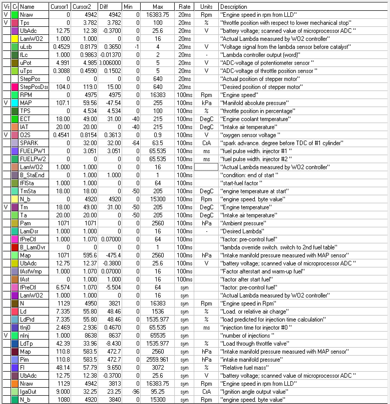
Figure 30. GX35 engine Test 0 sec to 411 sec. test data.
Figure 30 above shows the wide range of variables that are available for selection along with a description.
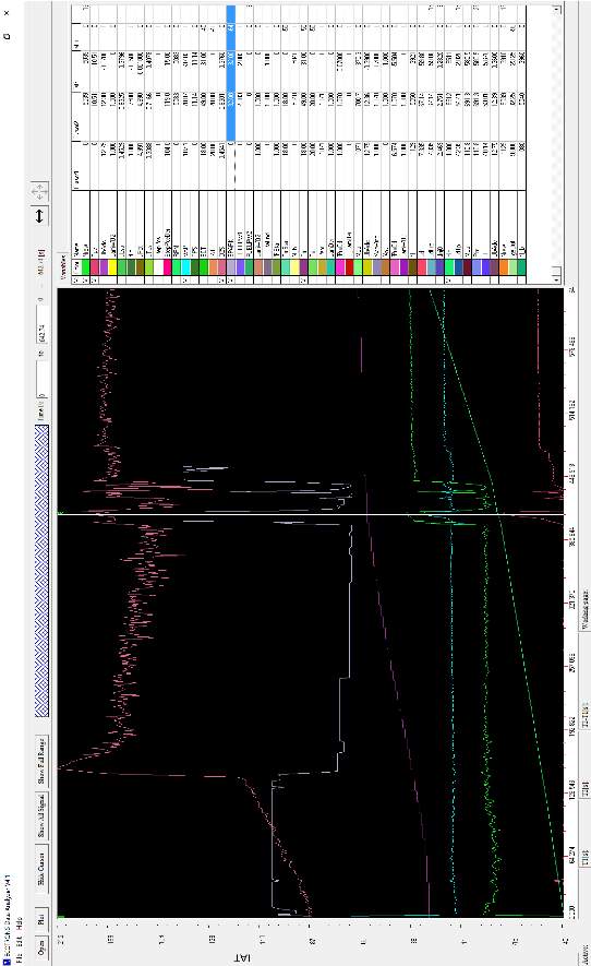
Figure 31. Engine test from 0secs to 411 secs. including spark timing.
In Figure 31. above the spark advance variable has been added to illustrate the system alterations caused by the increase in throttle input. As the rpm of the engine increases the spark needs to generate earlier. This is ‘spark advance’ or spark ignition timing adjusting to ensure combustion efficiency is maintained.
As well as allowing for precise calibration of the engine performance variables the software also provides a fuel consumption calculation feature. This will allow for comparison of different tuning settings to maximise output performance.
The ability of the ECU to manage performance can be augmented by variable input alterations in order to ensure the unit is tuned for the required environment. This will allow for adjustments based on type of circuit i.e. whether the track is made up of long straights or has changes in elevation.
4 Discussion
4.1 Limitations of Work
This project has endeavoured to establish a protocol by which a tuning regime will facilitate future work to improve engine performance. To identify areas of increased significance with regard to performance improvement and to gain an overall understanding of optimum energy output parameters.
The procurement of a stock engine of known outputs allowed the establishment of a tuning regime by which performance variables can be measured, recorded and ultimately changed to maximise engine performance for a given set of input values.
This facility can be used to ensure engine performance is maximised dependant on requirements which may be specific to a task, or indeed an environment.
The study was limited to engine performance and ‘stopped’ at the engine output and so it is important to note that in isolation, however fuel efficient an engine has been made, the fine tuning of an engine is of little effect if it is surrounded by inefficient systems.
As the power requirements for the engine is based on data such as vehicle mass, driver weight, frictional losses, and driving style. This project has endeavoured to allow for the development of an engine testing rig which will allow for variables to be adjusted as more ‘real’ data is developed.
The increased efficiency of an engine in a given situation can only be beneficial to system performance. However, any gains made in performance can be negated by a lack of efficiency in other areas. Whilst the scope of this study is to examine the engine it would be remiss not to mention the effect other components and assemblies within a system can have on performance.
The Eco marathon vehicle will benefit by a reduction in mass, the use of efficient bearings and appropriate wheels. Any reduction in mass will reduce the kinetic energy of the vehicle while in motion, particularly important on inclinations. Aerodynamic design consideration, reducing wind resistance, and drag forces will all reduce negative forces acting to retard the vehicle.
The project has developed a testing system including a baseline engine, an electronic fuel injection system and a recordable data analyser which will allow for the system to be utilised
5 Future Work
5.1 Future Work
The focus of the report was on understanding the process of altering engine variables to maximise performance within the confines of the standard engine and of the associated parts. This will be achieved by altering the variables within the confines of the stock engine. This will impose limits of performance based on the range of variation available. To move efficiency beyond the limits that these components will eventually impose it could be considered to alter or specify replacement components which could further improve efficiency.
There are a number of areas which are most appropriate for alteration / adaption.
5.1.2 Compression ratio
As explained in section (2.2.2) the compression ratio, the ratio of the volume of the cylinder and chamber at TDC compared to BDC, plays an important part in the power output of an engine. The higher the compression ratio the higher the power output. As a rule of thumb an increase in compression ratio from the Honda GX35™ 8:1 to 9:1 could improve fuel economy by 5 to 6 %.(Gilles,T. 2015). This could involve machining piston heads or alterations to stroke length. This alteration is limited by the tendency of fuel to ‘knock’ (2.2.2).
Machining out the cylinder to accommodate larger pistons could potentially increase power output.
5.1.3 Intake air Porting
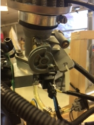
Figure 32: Air intake manifold in position.
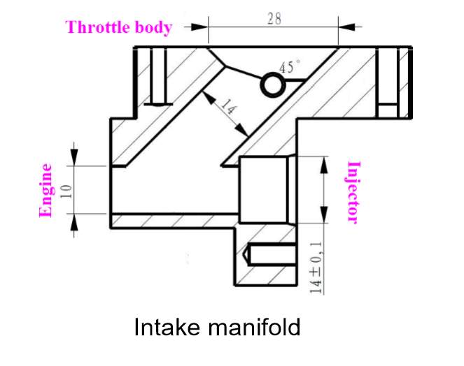
Figure 33: Intake manifold cross section.
The output power of the engine is dependent on the amount of charge (air) which is taken into cylinder. This figure can be defined as the ratio between the air taken in during an intake stroke against the capacity or swept volume of the cylinder. This ratio is known as the volumetric efficiency
Where;
ηv =
VintakeVswept (10)
Any increase in volumetric efficiency will improve engine power output.(EPI Inc. 2015) If the intake manifold can be reshaped to remove any sharp edges, polishing the internal surfaces, and reshaping valve heads to allow a smoother air flow volumetric efficiency will be increased. Figure 1. Above show the intake manifold in position. Figure 2. Shows the intake manifold in section. Alterations could be made to C.S.A. of fuel and air intake to increase the air intake rate removing sharp direction changes and ensuring connection to engine is as smooth as possible.
5.1.4 Dual spark ignition
On activation of the spark in a single spark plug system instantaneous combustion does not take place. The fuel air mixture is ignited at a single point and the flame moves in a wave across the mixture. This process takes a period of time. The introduction of multiple spark generation points could decrease the combustion time thus improving performance. Dual spark systems are not a new development and have been used in the aviation industry for many years for safety reasons. Within an automotive application a dual plug ignition system could increase the speed of the chamber combustion process delivering the power more rapidly.
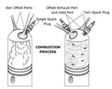
Figure 34. Single plug / Dual plug comparison Akhil, C.S. (2017)
The system DTSI (digital Twin Spark Ignition system) utilises a system where the twin plugs spark alternatively at a set time in order to burn the fuel instantaneously. The system is monitored by integrated electronic controls. Alterations to the profile of the cylinder head can help ensure rapid combustion. Akhil, C.S. (2017).
5.1.5 EcoEFI Small Engine Electronic Fuel Injection Tuning Guide
It is important to note that this software is not specifically for the tuning of ultra-efficient engines but is used by a wide range of users to optimise engine performance and calibration.
Accompanying the software is a 200 page tuning guide which will, with practice, allow the user to create a very sophisticated tuning setup. The software is set up in such a way as to allow it to be used almost immediately, in a rudimentary manner. However, it is important to note, this is not a ‘plug and play’ system and proficiency in operation will only be gained if appropriate time is invested.
It is clear from the number of parameters available for tuning that an in-depth study of the software would be required in order to become proficient in the operation.
Ecotrons do provide technical support and are happy to receive emails of data logs to offer tuning solutions to help novices learn the parameters.
In order to maximise the benefit of the software package it would be appropriate to carry out a further study on this to become fully conversant with the capability of the system.
The full version of the software manual can be downloaded from: https://tinyurl.com/mbcwwjv
5.2 Final Summary
Following a review of literature and reports pertaining to the Shell™ Eco Marathon, paying particular respect to engine performance requirements a baseline engine was identified and purchased.
This allowed for an investigation into engine operation and the development of an understanding of tuning regime requirements. This led to the procurement of appropriate ancillary devices in order to adapt the engine to ensure Shell Eco Marathon rule compliance.
These included the Ecotrons™ electronic fuel injection kit and the EcoCAL™ Data analysis software.
The modifications to the engine allowed further investigation into operating parameters. The fitting of the fuel injection system and fabrication of the test mounting frame, with output connection to P.C. enabled engine parameters to be measured, recorded and clearly displayed on the P.C. monitor.
Going forward the software systems can be learned. The Ecotrons system is a automotive professional based system and as such requires a depth of knowledge. To maximise benefit from the output from system time needs to be spent learning appropriate operation.
The software has the ability to feedback many variables see (Fig.30) allowing for alterations to be made to maximise engine efficiency.
As the other aspects of the Eco marathon vehicle are developed, body, chassis, drive train, etc., more data will be available to feed in to the system to begin the creation of an engine mapping based on actual performance requirements.
The project could have benefitted from the tandem development of the other vehicle components to create an investigation, with a feedback loop of information to allow for testing and development.
An amalgamation of disciplines going forward, with the testing regime in place, should benefit from the ability to be able to identify, test and adjust engine parameters to optimise overall vehicle performance.
6 References
AA1Car (2017) How Electronic Fuel Injection Works, Available at: http://www.aa1car.com/library/fuel_injection_basics.htm (Accessed: 14th March 2017).
Acosta,B.,Betancourt,M.,Pinheiro,F. (2012) Shell eco-marathon, Florida, USA: FIU Department of Mechanical and Materials Engineering.
Adeniyi,A, Mohammed,A (2012) ‘A Shell eco marathon concept engine design’, Academic Research International , 2(2223-9944), pp. 125-136.
Akhil, C.S. (2017) DTSI (Digital Twin Spark Ignition System), Available at: http://automobiletechinfo.blogspot.co.uk/2013/09/dtsi-digital-twin-spark-ignition-system.html (Accessed: 14th March 2017).
Akinnola, A Ghaniyu, A. Mohammed, A. (2012) ‘A Shell eco marathon concept engine design’, Eco-marathon car driving pattern and miles per gallon, 15(246-253), pp. 246-251.
Cengal,Y. cimbala,J. (2012) Fundamentals of Thermal-Fluid Sciences, 4th edn., Asia: McGraw-Hill Education.
Ecotrons (2017) Honda GX35 Engine Fuel Injection Kit, Available at: http://www.ecotrons.com/products/honda_gx35_engine_fuel_injection_kit/ (Accessed: 23rd April 2017).
EPI Inc (2011) Piston Engine Technology, Available at: http://www.epi-eng.com/piston_engine_technology/engine_technology_contents.htm (Accessed: 15th March 2017).
EPI Inc. (2015) Volumetric Efficiency and Engine Airflow, Available at: http://www.epi-eng.com/piston_engine_technology/volumetric_effi (Accessed: 14th March 2017).
Everett,B., Boyle,G., Peake,S. Ramage,J. (2003) Energy Systems and Sustainability, 2nd edn., United States: Oxford University Press.
Fuel Oils UK (2017) http://www.fueloils.co.uk, Available at: http://www.fueloils.co.uk/downloads/downloads-sub/downloads-fuels (Accessed: 13th March 2017).
Gamble,J., Glassy, N., Moore,T. (2013) Shell Eco-marathon Concept Generation and Selection, Northern Arizona University Flagstaff, AZ 86011: Department of Mechanical Engineering.
Gilles, T. (2015) Automotive Service book. 5th edn. Boston: Cengage.
Heywood, John, B. (1988) internal combustion engine fundamentals, New York: McGraw-Hill.
Honda Motor Co. Inc. (2017) Honda Motors, Available at: http://engines.honda.com/models/model-detail/gx35 (Accessed: 3rd Janurary 2017).
IPCC (2013) The Physical Science Basis. Contribution of Working Group I to the Fifth Assessment Report of the Intergovernmental Panel on Climate Change, New York, USA: Cambridge University Press.
Karthikeyan,G. Ramajayam,M. Pannirselvam, A. (2013) ‘Design and Fabrication of an Electronic Fuel Injection Kit for a Conventional Small Capacity SI Engine’, International Journal of Engineering and Advanced Technology (IJEAT), 2(4), pp. 525-527.
McAllistar,S. (2011) Fundamentals of combustion Processes, New York: Springer.
Mengistu,H./Air Force institute of Tech Wright-Patterson (2011) Small internal combustion engine testing for a hybrid electric remotely piloted aircraft, Ohio, USA: Air Force institute of Tech Wright-Patterson School of Engineering and Management.
Meriam, J.L., Kraige, L.G. (2013) Dynamics, 7th edn., New York: Wiley.
OECD/IEA (2007) World Energy Outlook 2007, Paris: International Energy Agency.
Power4Flight (2017) Power4Flight The Benefits of Electronic Fuel Injection (EFI), Available at: http://power4flight.com/benefits-of-efi/ (Accessed: 3rd March 2017).
Rouwendal.J (1995) ‘An Economic Analysis of Fuel Use Per Kilometre by Private Cars’, Journal of Transport Economics and Policy, 30(), pp. 4.
Shell Global (2016) About Shell eco marathon, Available at: http://www.shell.com/energy-and-innovation/shell-ecomarathon/about.html (Accessed: 3rd November 2016).
Shell Global (2016) SHELL ECO-MARATHON 2017 OFFICIAL RULES CHAPTER I. [Online]. Available at: http://www.shell.com/energy-and-innovation/shell-ecomarathon/_jcr_content/par/toptasks_16 (Accessed: 20th March 2017).
Tian,T. (2002) ‘Dynamic behaviours of piston rings and their practical impact. Part 2: oil transport, friction and wear of ring/liner interface and the effects of piston and ring dynamics.’ Journal of Engineering Tribology, 216(4), pp. 229-248
7 Appendices
7.1 Appendix A Shell Eco Marathon Rules (Engine Section)
7.2 Appendix B Unleaded Petrol 95 Specification Data Sheet
Cite This Work
To export a reference to this article please select a referencing stye below:
Related Services
View allRelated Content
All TagsContent relating to: "Automotive"
The Automotive industry concerns itself with the design, production, and selling of motor vehicles, such as cars, vans, and motorcycles, and is home to many multi-billion pound companies.
Related Articles
DMCA / Removal Request
If you are the original writer of this dissertation and no longer wish to have your work published on the UKDiss.com website then please:


