Monitoring System for Formula Student Car using Lithium-based Battery
Info: 11621 words (46 pages) Dissertation
Published: 13th Dec 2019
Tagged: Information SystemsAutomotive
Monitoring System for Formula Student Car using Lithium-based Battery
Project background
The prime objective of formula student challenge, is to design and develop a comprehensive formula car that can take a part in the annual formula student challenge event. Notably this comprehensive design will be shared between all the engineering schools within the campus, which is allowing a group of student to work together as professional team, and share their knowledge to complete this project, and potential of winning this completion within the formula student rules.
To promote the design and increase the winning possibility, the campus formula car constantly subjected to technical improvement and additional features. As part of this improvement, the team decided to replace the conventional lead-acid battery with a modern technology (lithium-based battery),
This report, deliver a comprehensive case study about the characteristic of this battery, as well as it changing behaviour under different conditions to ensure it compile with this design, beside the practical work which consist on design and develop a monitoring system for this this battery, alongside apply this system to the battery under different conditions to ensure safe operation of this technology, by delivering a valuable parameters value to the driver and team members to improve the performance of the vehicle.
Monitoring battery system is very important feature. Since the essence of this feature is to detect whether the battery has enough energy to start the engine and deliver an appropriate power to car’s equipment, beside detect whether the alternator is sending a suitable energy to charge the battery, therefor this system can help to diagnose any faults within the cars electric system when occurs. Notably sending data about battery condition can determine the quality of the car performance, as well as it life cycle.

Abstract
This report, contain a complete case study about monitoring system requirement of lithium-based battery, to ensure this highly powered technology is compile with Formula Student Car, to improve its performance.
Lithium-based batteries has several advantages over the conventional battery at the cost of extra monitoring device beside the control overhead. //
This paper present an overview of the control and management requirement of high power lithium based batteries for Formula Student Car. Lithium-based battery technologies offer performance advantages over traditional battery technologies at the cost of increased monitoring and control overhead.// The additional complexity of drive system based on this type of technologies increases the management burden for the accurate state of charge prediction, state of health prediction cell balancing.
The common fact with a conventional cars (lead acid batteries) is the use of a battery to store electrical energy to sustain high performance, long lifetime and safe operation. It is important to control the temperature of lithium-based battery cells by considering a sufficient and well-designed cooling system.
In this report, monitoring the battery in the formula Student Car is developed and discussed. The first part of the report provide a comprehensive case study about the characteristic of this type of technology and investigating the car’s electric system.
Eventually the last part is analysing predesigned the System as well as determine the best method of monitoring used in this design, and how to measure battery parameters (Volt, Current, Temperature, power Consumption and Battery Percentage), with equipment used.
Introduction
Lithium is the highest of all metal, it has the best electrochemical potential and provide the biggest particular vitality energy per weight. Rechargeable batteries with lithium metal on the anode could give phenomenally high energy densities. The energy density of lithium-based battery is ordinary twice that of the standard nikel-cadmium. Recently, lithium-based battery is the quickest development and most encouraging battery science.
Lead is a classified as very heavy metal thus, the research took plce for many years to improve battery’s weight issues beside its power density.
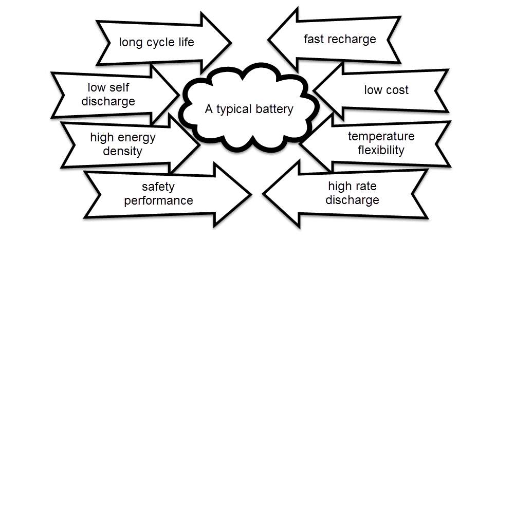
Then lithium-based batteries become the logical choice to replace lead as it has the following
- Longer life cycle
- Faster recharging
- Lower cost
- Operate at a varying temperatures
- Higher energy density
- Lower self-discharge
- Higher rate discharge
- Safer as long as it maintained properly
Lithium is a very receptive and consequently unadulterated. Lithium is never found in nature, Lithium metal is produced from lithium salts which are removed from mining.
Overall lithium-based batteries have beneficial features that have made them the best choice in many application. Lithium is the metal with both the lowest molar mass and the greatest electrochemical potential. This mean that lithium-based batteries can have high energy density. A usual lithium pack (lithium cobalt oxide-carbon) approximately is 3.6 V. and significantly their self-discharge is approximately 5% lower than NiCad batteries, notably its self-discharge at 20%. In addition these battery packs does not consist on those types of dangerous heavy metals (cadmium and lead). Finally lithium-based batteries do not have any memory effects and also do not need to be refilled with an electrolyte. This makes them lower maintaining comparing with lead-acid batteries.
Literature Review
The chemist John Goodenough include his colleagues Phil Wiseman, Koichi Mizushima, and Phil Jones, were the first people to successfully produce practically valuable lithium-ion power packs, which their experiment took place in Oxford University in 1970s. After publishing their research in 1980, Sony firm turned this metal into a commercial technology, who produced the first lithium-ion batteries in early 1990s. Since then they’ve become commonplace. Which has since become popular and kept its place as the best choice of rechargeable batteries.
One of the lithium-based battery advantages, that it is not require any maintaining process within its life-cycle. No planned cycling is required, and there is no memory impact in the battery. Besides, the lithium-base battery is suitable choice for Formula Student Vehicle, since its self-discharge rate is not as much as half of the discharging rate of the lead-acid and NiMH batteries. Despite the advantages of lithium-based batteries, they also have few drawbacks. Lithium-based battery are brittle. Also it is very sensitive to amount of voltage and current that charging and discharging the battery, beside an extra attention to temperature that this battery face during it working time. To avoid any fault or failing status, a suitable device is required that detect any changes on those facts, and delivering a comprehensive data about battery conditions, to determine it performance. This technology, additionally alluded to as the Battery Management System (BMS), confines the peak voltage of every cell amid charging and keeps the cell voltage from dipping under threshold during discharging. Also the (BMS), controls the maximum charging and discharging currents and monitor the cell temperature.
Lithium-based battery challenges
The most eminent essence that declares the performance of the lithium-based battery, are the operating temperature, current and voltage. Current and temperature must be maintained within the area indicated by Safe Operation Area (SOA) at all times, which represent under maximum voltage, current and temperature curve. The battery could be permanently defective if it is operated outside the safety zone. The batteries should not be charged such that its voltage exceeds its rated voltage or be discharged such that its voltage falls below the minimum recommended voltage.
The recommended upper limit of charging voltage for a lithium cell is 4.2V per pack. If this value is exceeded while charging, a high current will flow and causes in lithium plating and overheating. Not much from charging cycle, overly discharging the packs or storing them for long time would cause the packs voltage to drop below its lower limit, typically 2.5V, this could gradually break down the electrode.

Alternator and Charging System Checks
The electrical system of a car is a classified as closed loop circuit with a separated power source which is the battery. Notably this battery operate on a sort duration within this circuit that is will stops as soon as the engine is cranked.
The current will flow from the battery along a particular cable to the starter after turning the switch on. When the engine is running, the battery and the all other car’s electric system will be powered by the engine. Otherwise when it is off, the battery will proceed with powering this system. Thus, connecting car’s body to the earth is required, which is can be done by connecting it with battery’s negative terminal with suitable cable.
How Car Electric System Work
The car’s electric system consist on four main circuits.
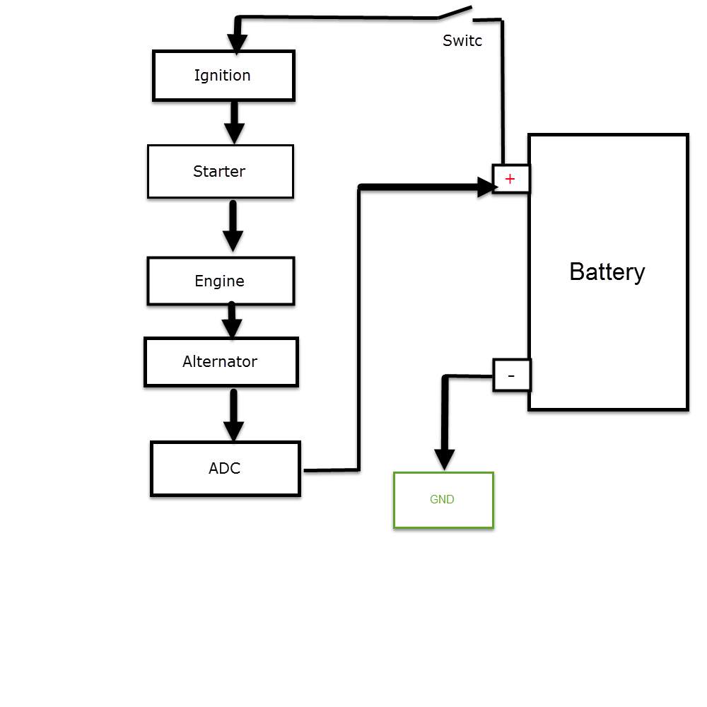
- Starting circuit, where the battery supply current to the starter when turning the switch on, and the starter amplify this current to make it suitable for spark plugs to start the engine.
- Charging circuit, where the engine crank the alternator, that induce current through electromagnetic procedure, and deliver this current back to charge the battery after rectifying it (converting from AC to DC), and regulated since the current value will vary due to engine speed variations.
- Powering loads circuit, where the battery and/or the alternator supply power to car’s electric equipment.
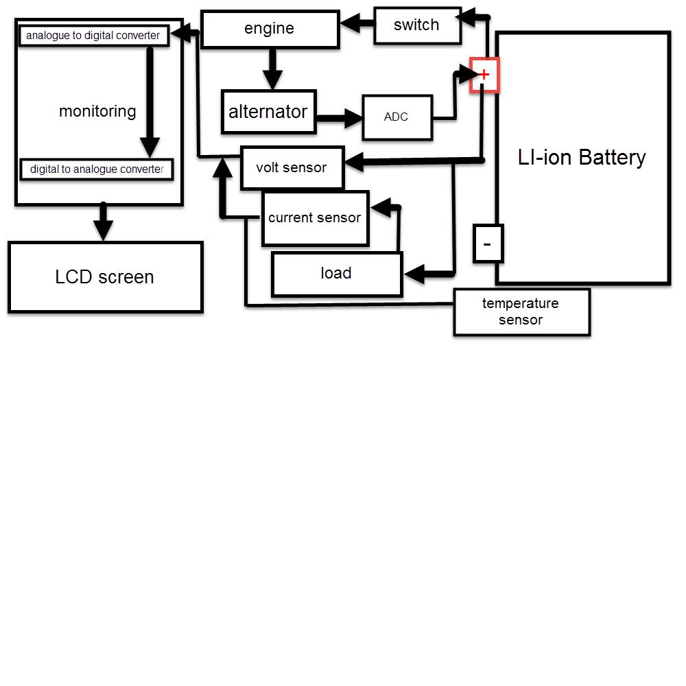
- Monitoring circuit, where a monitoring is detecting battery’s parameters to determine it status.
Car electric system component
| Switch | Ignition | Battery | Starter | Alternator |
| Engine | Spark Plugs | BMSs | Wiring Loom | Fuses |
Electric circuit that powered by the battery when the engine is off, and power by the alternator when the engine is on
| Heated rear window | Fuse box | Sensors | Gauges |
| Windscreen-wiper motor | Indicator | Electric fan | washer pump |
| Electrically operate radio aerial | Headlamp | Distributor | Heater |
| Electrical instrument | Magnetically operated locks | CD player | Electric motors |
The above circuits are generally operating by switch or relays, to active the circuits or open them.
Earth-return system
When powering a particular electric equipment that connected to the battery, the current delivered from the battery’s positive terminal (+) to that equipment. Notably the other side of this equipment is earthed to car’s bode, which connected to the battery’s negative terminal (-).
When the negative side of this equipment connected to the car body, which earthed by the battery negative terminal, it is called earth-return circuit.
The current strength is determined in amperes (amps); the pressure that causing it to flow around the circuit is called voltage (volts). In the late cars, the battery voltage is approximately 12volt. Beside it the battery’s capacity is determined in amp/hours. A 50 amp/hour battery should be able to deliver a current of 1 amp for 50 hours, or 2 amps for 25 hours.
When battery voltage fall, the flowing current strength will decrease. Thus, due to the lack of power it prevent the electric equipment from working.
When the electric current flows within a wire, it face a particular resistance from this wire, this gauge of resistance is determined in ohms.
Since thin wire has more resistance than thick once, beside, that thick wires has more place for the electrons to move through, thus, the conductance of the thick wires is greater than the thin once.
Notably the resistance that current facing during it flowing cycle is transmitted to heat.
This can be useful, for instance in the very thin string of a light bulb, which glows white hot. Thus, a thin wire is the most suitable connecting choice for those equipment that relay on high current consumption. Otherwise the alternative choice will cause turn the fuse to be defective or blow it, due to the overheated wire. Significantly the determination of the electrical units engaged: for instance a pressure of 5 volt cause a current of 5 amp to flow through a resistance of 5 ohms.
For ohm’s law, amp is equal volts over resistance. I =
VR, for instance the current consumption for a bulb with a resistance of 5 ohms, and 10 volts pressure is equal to 2 amps.
Therefor the thickness of wire connected with this bulb must be suitable to handle 5 amps without any problems.
To determine the power consumption of this blub, simply is multiply the current by the voltage which measured in watts. In this case the bulb consumption is 20watts.
Positive and negative polarity
Current flowing in a single direction from the battery, when a component connected in wrong way, the component will not work as the current flowing into it from the earthed side, possible causes defection.
Therefor the battery power the system through it positive terminal (+), notably the negative one (-) is earthed to the ear-thing point.
Short circuits and fuses
A short circuit occurs for many reasons, the most common one that, using wrong thickness of wires, as well as wires different wires touching each other. The impact of the short circuit incidence is the resistance of the component will be bypassed, which causes damaging the wire and possibly catch a fire, due to high flowing current.
Fuse box // puts figure for fuse box
Usually fuses are combined together within a water and heatproof box, that siled properly to be protected from any external affect. The aim of these fuses is to protect the component from over-flowing current, as well as any defective problems, as they consist on a short length wire, that will prevent the current from flowing, when it disconnected by the cause of high amps current.
Thus, the best fuse type are those with short-thin wires. Therefor these fuses provide a big benefit that, protect the system component and reducing the cost of replacing equipment when short circuit is occur.
Notably it is highly recommended to install an individual fuse for each component, which allow those component to work independently, when a short circuit occur, other component won’t be affected. Also those fuses are earthed on the other side by fuse box ground point.
Circuit types
Mainly there are two different type of circuits that used in electric system
- Parallel circuit, where the component connected beside each other, thus, they share the same amount of power.
- Series circuit, where followed by the other within same line connection, thus the power they receive is different.
In la amp application, the glowing factor occur when a particular amount of current consumed by it resistance, which depends of the value of this resistance.
So when two resistors connected in series, the resistance that current face will increase, causes decreasing in lamp glowing density. Notably in a parallel type, the number of resistance has no impact of the glowing lamp density.
An example of the series connection within car’s electric system, is fuel level sensor that deliver an electric signal the fuel gauge, due to the variation of its resistance is depend on the fuel level within the tank
Ancillary circuits
Battery connected to the starter with an independent cable, and the starter with ignition beside the spark plugs form the circuit that turn the engine on by the high-tension current amplified within the ignition, due to the electromagnetic process, and, delivered to the spark-pugs that fire the engine.
Once the engine start running, it crank the alternator, which induces and alternating current, that converted to DC current to charge the battery. The insularity circuits are those connected to the ignition, which is mean they depend on the ignition to be active. The benefit of this type of circuit, is protecting the battery from total discharge when switching on some electric equipment. Notably some other circuit who consume low current, most be wired independently from the battery, like front and back light, allowing them to work even when the engine is off. While other circuitries who consume high current, are usually connected to the ignition circuit.
In additional some other equipment that wired to the ignition circuit, can work without turning the engine on, by turning the starting switch to auxiliary position.
Wires and printed circuits
In this type of circuit, wires and cable size, declares the maximum acceptable current that key can handle, and the instrument connection located at the sides of these circuit are subjected to fraction the integral catches. Thus, a combination of many electric cables and wires installed within the car. The solution of not misconnect these wires are to colour code them.
To make this cable installation organised and tidy, attaching all cables that goes in the same directions within isolated bundles. The entire bundles and wires known as wiring loom. That covers all around cars body.
Diagnosing the battery
Generally, battery and ignition circuit are the causes of starting problems when occur, in some cases, diagnosing the electrical problems is a complex issue, such as intermittent problem. Thus, during resolving electrical problems, some component is replaced unnecessarily due to the difficulty of diagnosing electrical issues.
Mainly, a low battery voltage is the cause of starting and drive ability problems, which is relay on a simple procedure to diagnose. The low battery voltage has several impact on the car electric system, for instance, low battery can case difficulty of starting and possibly misfire due to the insufficient current that the injectors receive. Also the impact of low voltage battery is significant on the fuel pump, by casing low fuel pressure, due to slow running fuel pump.
One of the disadvantages of lead-acid battery, when it fully discharged, a significant of chemical changing behaviour occur on lead plate located within the lead battery. A symptoms of low bower battery occur, due to the sulphate layer cover the lead plate that prevent the battery from charging. Therefore, keeping this battery at or near full charge at all the time is crucial.
Approximately, between four to five years is the average battery life in typical conditions. Battery’s power can be decreased up to 50% when the temperature dropped to 20 F degrees, notably the suitable current to start the cold engine is almost twice amps at this temperature. Thus, the impact of varying temperature on batteries is significant.
Ways of checking the battery
There are many ways to determine battery’s conditions, the most accurate one, is using a digital voltmeter, that display battery parameters values as a digital number.
Battery’s voltage is no reliable to determine battery status accurately, as a fully charged battery is a most of the cars is approximately 12.65V. when discharging this battery to 75%, the readying display 12.45V. therefore the most accurate way to determine battery status is by measuring the battery’s energy.
Also, a fully charged battery may not be able to start the engine or even the battery may be defective, as the main concern when starting the engine, is that the battery can deliver a suitable current when applying a particular load on it.
Determine the battery status
Two ways to determine battery status:
- By applying a load testing with a tester that calibrate the load on the battery, which is requires the battery to be fully charged for accurate test results.
- By testing with an electronic (conductance) tester, which does not require a fully charged battery for accurate test results.
How conductance testers works
Conductance tester deliver a frequency signal though the battery to determine the volum active plate area is available to hold and send power. As the battery ages, its conductance decline. Bearing in mind that sorts, opens and other defects also affect conductance. Therefor measuring conductance gives an accurate indication of the battery condition.
Generally many electronic battery testers also determine battery’s Cold Cranking Amp (CCA) capacity, which can be used to estimate the battery’s remaining service life. Also some testers measure the amps drawn by the starter while cranking the engine, and analyse the charging system’s output under load once the engine is running.
Therefor if the vehicle needs a new battery, it should have the same or higher CCA rating as the original equipment battery specified by the vehicle manufacturer. Technically batteries should be fully charged before installing them, where other items that should always be inspected and may need to be replaced include the following
- battery cables
- anti-corrosion washers (for battery terminal)
- Battery tray and/or battery hold-down hardware
- Clamps
Checking the charging system
The vehicle charging system consist on the following component
| Alternator | Starter | Ignition | Spark plugs | Spark plugs wires | Ignition coil | Ignition module |
It is very important to check vehicle’s charging system to make sure it is operating correctly and capable of keeping the battery at an appropriate charging level. As standard, the charging voltage with the engine at fast idle should usually be about 1-1/2-2 volts higher than battery voltage.
Alternator checks
The alternator charging output increments in corresponding to the electrical load on the charging system and motor speed. Charging output is controlled by voltage regulator, which may be mounted inside or on the back of the alternator (internally regulator), or somewhere else under the bonnet (externally regulator). In recent vehicles, the powertrain control module (PCM) regulates charging output.
If the alternator is overloaded, it may overheat and fail. An alternator failure will cause the battery to run down and it becomes flat. There are many symptoms of charging problems such as
- Dim headlights
- Hard starting
- Charging system warning light
Eventually bench testing an alternator is a good way to verify the diagnosis and/or to confirm the output of the alternator.
Starter checks
An engine that won’t crank may have a bad starter, or it may have another fault such as
- Bad starter solenoid starter drive
- Problem in the ignition switch circuit
- Park/neutral or brake safety switch circuit
- Anti-theft immobilizer system
Therefor if the battery is fully charged and the starter is receiving normal battery voltage but fails to crank or crank slowly, it indicates that the starter is defective and probably need to be replaced.
The most common cause of the starter failure are the following
- Prolonged cranking, which causes the motor to overheat.
- Brushes, bushings, starter drive become worn, due to long term of usage.
- Defective starter solenoid, a defective solenoid will prevent the starter from working. This solenoid routs current to the motor when the ignition switch is turned to crank position.
- The starter drive mechanism that engages the flywheel may also stick or fail, which prevent the starter from working.
Starter technical fact
A replacement of new starter must have the same bolt pattern and electrical connections as the original, and the same number of teeth on the drive gear. It is crucial to handle permanent magnet starter with care because the magnets are brittle and can be easily cranked if the starter drops, related items may also be replaced include battery cables and engine ground straps.
Ignition diagnosis
Primary and secondary ignition patterns can reveal a great deal about the health and performance of the ignition system. Reading ignition patterns on a scope it gives a good data about the ignition status.
Spark plugs diagnosis
Spark plugs wear out (even long life 100,000-mile), and can become fouled by carbon deposits. The impact of defective plug is losing power and potentially fuel economy and exhaust hydrocarbon (HC) emission issue, which may eventually damage the catalytic converter. Defective or worn spark plugs can cause difficulty of starting the engine and poor performance.
Spark plugs wires diagnosis
The spark plugs wires (ignition cables) carry high voltage from coil or distributor to the spark plug.
Significantly plug wires can deteriorate with the following
- Defective plugs
- Starting problems
- Poor performance
Wires should be replaced if the boots or terminals are loose, damaged or corroded in the following conditions
- If the wires are cracked.
- Sparking.
- The internal resistance of the wires exceeds specifications.
In the recent model engines the coils are mounted directly on the spark plugs, which is no need for plug wires there are no plug wires. To pick up an induced ignition signal from the coils, requires a special adapters, which causes difficulty for ignition diagnosis with a scope.
Ignition coils diagnosis
Coils seldom fail, but when they do they can’t provide voltage to the spark plugs.
Ignition coil types
- Single coil ignition system, a coil failure will cause the engine to quit and prevent it from starting.
- Multi-coil DIS or COP ignition system, coils failure will cause a misfire in only the cylinder supplied by the bad coil.
Testing the Coils requires measuring their internal resistance using an ohm meter. If the coil’s primary or secondary resistance is out of specifications, mean the coil defective.
Ignition module diagnosis
Ignition module may receive a trigger signal directly from the following
- A distributor pickup (magnetic, Hall effect or optical)
- A crankshaft position (CKP) sensor or the PCM.
A fault in any of these component or the wiring can prevent the ignition system from firing.
Therefor loss of spark indicates that the ignition module is defective, or that it is losing its trigger signal from the crank sensor.
The module approach the end of his life cycle, if the module has good inputs, but is not switching the coils on and off.
Facts to consider when replacing lead-acid battery with lithium-based battery
Battery research is focusing on lithium chemistries, the battery future lies solely in lithium-based battery. There are many reasons to be optimistic as lithium-ion is in many ways, superior to other chemistries. Applications are growing and are encroaching into markets that previously were solidly held by lead-acid battery, such as standby and load levelling, many satellites are also powered by li-ion.
Lithium has not yet fully matured and is still improving. Notably advancements have been made in longevity and safety while the capacity is increasing incrementally. Now day, most consumer devices are relay on lithium-based batteries, further more development required for some applications like but EV before this power source trustful.
Lithium-based battery characteristic
The lithium-based battery works on ion movement between the positive and negative electrode. In theory such a mechanism should work forever, but cycling elevated temperature and aging decrease the performance over time. Manufactures takes a conservative approach and specify the life of Li-ion in most consumer products as being between 300 and 500 discharge/charge cycles.
Evaluating battery life on counting cycles is not conclusive because a discharge may vary in depth, and there are no clearly defined standards of what constitute a cycle. A battery may fail within the allotted time due to heavy use or unfavourable temperature conditions; however, most packs last considerably longer than the stamp indicates.
Therefor the performance of a lithium-based battery is measured by the following facts
- By the capacity
- A leading health indicator
- Internal resistance
- Self-discharge
Bearing in mind these facts are less significant in predicting the end of battery life with modern Li-ion.
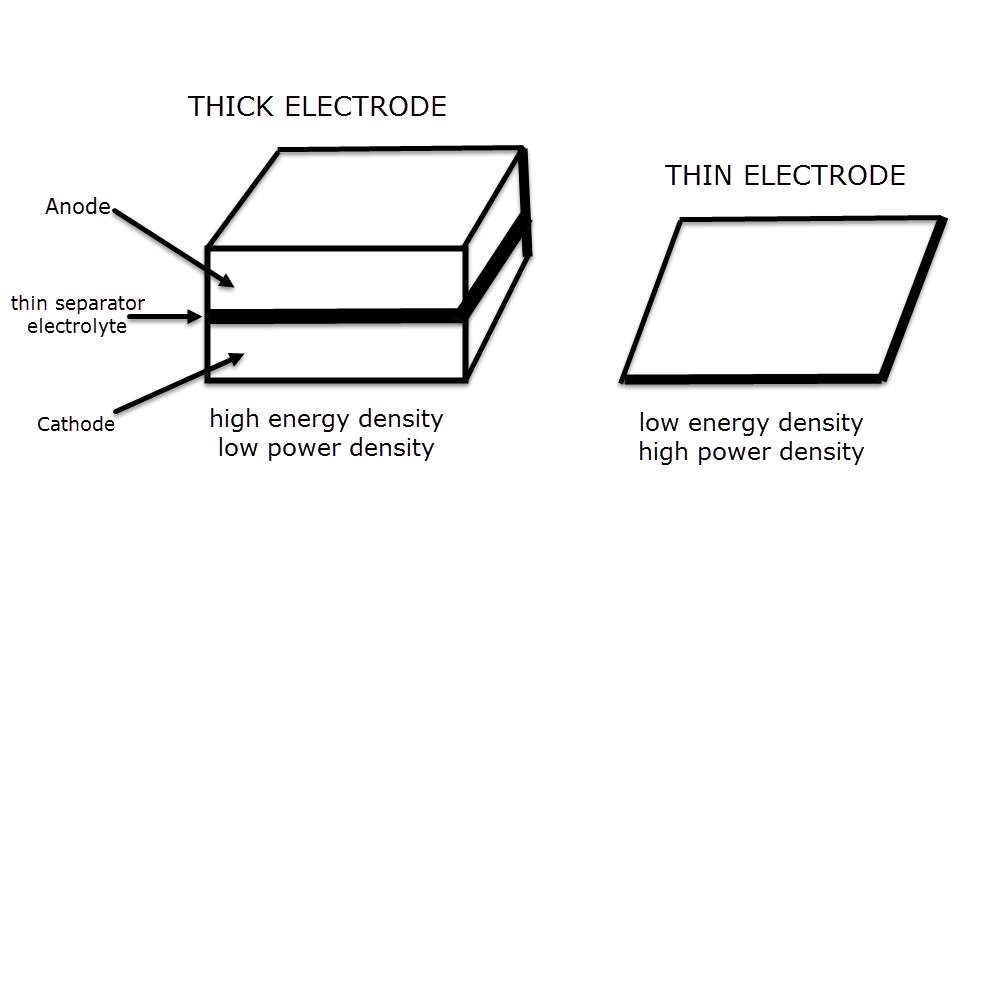
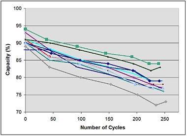
Figure (1), illustrate the capacity drop of 11 Li-polymer batteries that have been cycled at a codex laboratory. The 1,500m Ah pouch cells for mobile phones were first charged at a current of 1,500mA (1C) to 4.20V/cell, and then allowed to saturate to 0.05C (75mA) as part of the full charge saturation. The batteries were then discharged at 1,500mA to 3.0V/cell, and the cycle was repeated. The normal limit loss of Li-ion batteries was uniform over conveyed 250 cycles, and the batteries function as expected.
//need to put figure number//
Figure (1): capacity drop as part of cycling. Eleven new Li-ion were tested on a codex C7400 battery analyser. All packs started at a capacity of 88_94% and decreased to 73_84% after 250 full discharge cycle.
Courtesy of Codex // maybe change title //
Although a battery should deliver 100% capacity during the first year of service, it is common to see lower then specified capacities, and shelf life may contribute to this loss. In addition, manufacturers tend to overrate their batteries, knowing that very few users will do spot-checks and complain if low. Not having to match single cells in mobile phones and tablets, as is required in multi-cell packs, opens the floodgates for much broader performance acceptance. Cells with lower capacities may slip through cranks without the consumer knowing.
Very identical to a mechanical device that defect quicker with heavy use, the battery’s cycle count depends on the depth of discharge (DOD). The smaller the discharge (low DOD), the longer the battery will last. If at all possible, avoid full discharge and charge the battery more often between uses. Partial discharge on Li-ion is accepted. This battery does not require a complete discharge cycles as there is no memory effect. The exception may be a periodic calibration of fuel gauge on a smart battery or intelligent devices.
Table (2) compare the number of discharge/charge cycles Li-ion deliver at various Depth of discharge (DOD) levels before the battery capacity drops to 70%. All other variables such as charge voltage, temperature and load currents are set to voltage default setting. (DOD) constitute a full charge followed by a discharge to the indicated percentage levels in table.
| Discharge cycles | Depth of discharge | Table 2: Li-ion life as a function of the depth of discharge. A partial discharge reduces stress and prolongs battery life. Life cycle can be affected by high temperature and high currents. |
| 300–500
1,200–1,500 2,000–2,500 3,750–4,700 |
100% DoD
50% DoD 25% DoD 10% DoD |
Lithium-ion suffers from stress when exposed to heat, so does keeping a cell at high charge voltage. A battery dwelling above 30°C (86°F) is considered elevated temperature and for most LI-ion a voltage above 4.10V/cell is deemed as high voltage. Exposing the battery to high temperature and dwelling in a full state-of charge for an extended time can be more stressful than cycling.
The following table demonstrates capacity loss as a function of temperature and SoC
| 40% charge | Temperature | 100% charge | Table 3: approximated battery’s capacity status after a year of storing within different level of temperature. High temperature causes quick permanent capacity loss. With Li-ion it has the same impact. |
| 98%
96% 85% 75% |
0°C
25°C 40°C 60°C |
94%
80% 65% 60% |
Most Li-ions charge to 4.20 V/cell and every reduction in peak charge voltage of 0.1V/cell is said to double the cycle life. For instance, a lithium-ion cell charged to 4.20V/cell typically delivers 300_500 cycles. When charging to 4.10V/cell, the life will be extended to 600_1,000 cycles. 4.0V/cell experimentally provide 1,200_2,000 cycles and 3.90V/cell approximately provide 2,400_4,000 cycles.
A lower peak charge voltage on the negative side, decreases the capacity storage of the battery. As a simple guideline, every 70mV reduction in charge voltage lowers the overall capacity by 10 percent. The battery’s capacity restores fully when applying the peak charge voltage on a following charge.
In regard to longevity, the typical charge voltage is 3.92V/cell. Significantly this threshold eject almost all the voltage-related stresses, proceeding lower may not gain further benefits but potentially induce other symptoms.
Table (4) summarizes the capacity as a function of charge levels. (Energy cells with higher voltage thresholds may deviate)
| Charge level (V/cell) | Discharge cycles | Available stored energy | Table 4: Li-ion life as a function of the depth of discharge. For every 0.10V drop under 4.20V/cell doubles the cycle and keeps less capacity. The more the voltage above 4.20V/cell would the less the longevity. Guideline: for every 70mV drop in charge voltage reduces the usable capacity by approximately 10%. |
| [4.30]
4.20 4.10 4.00 3.90 3.80 3.70 |
[150 – 250]
300 – 500 600 – 1,000 1,200 – 2,000 2,400 – 4,000 >4,000 |
~[114%]
100% ~86% ~72% ~60% ~40% ~30% |
Table (4) represents discharge cycles and capacity as function of charge voltage limit. For every 0.10V drop under 4.20V/cell doubles the cycle and keeps less capacity. The more the voltage above 4.20V/cell would the less the longevity.
For safety reasons, many lithium-ions cannot exceed 4.20V/cell. While higher voltage boots capacity, exceeding the voltage shortens service life and compromises safety. Figure (5) demonstrate cycle count as a function of charge voltage. At 4.35V, the cycle count of a regular Li-ion is cut in half.
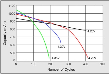 |
Figure 5: impact on cycle life at high charge voltages. Higher charge voltages increase capacity but decrease cycle life and compromises safety.
Source: Choi et al. (2002) |
For a particular applications, not only setting the most-suited voltage thresholds, it requires a regular Li-ion not to remain at the high-voltage ceiling of 4.20V/cell for prolonged time. The Li-ion should not remain at the high-voltage ceiling of 4.20V/cell for an extended time. The Li-ion charge turns off the charge current and the battery voltage return to a more natural level.
Technical facts need to be considered when dealing with lithium-based battery
- Environmental conditions, not cycling alone, govern the longevity of lithium-ion batteries. Keeping a fully charged battery at high temperatures is the most dangerous situation, which may cause the battery to explode.
- Battery packs do not die suddenly, but the runtime gradually shortens as the capacity fades.
- Lower charge voltages prolong battery life.
- A normal car battery could be prolonged by lowering the charge voltage when connected to the AC grids. To make this feature user-friendly, a monitoring device should satisfy a long life mode that keeps the battery at 4.05V/cell and provide a capacity of about 80 percent. One hour before using the Formula Student car, it is advised to keep the battery at full capacity mode which bring the charge to 4.20Vlcell.
- Disconnect the battery from power grids when it is fully charged. Bearing in mind the design aim is to topping charge to the battery only when its voltage drops to a certain level.
How lithium-based battery works
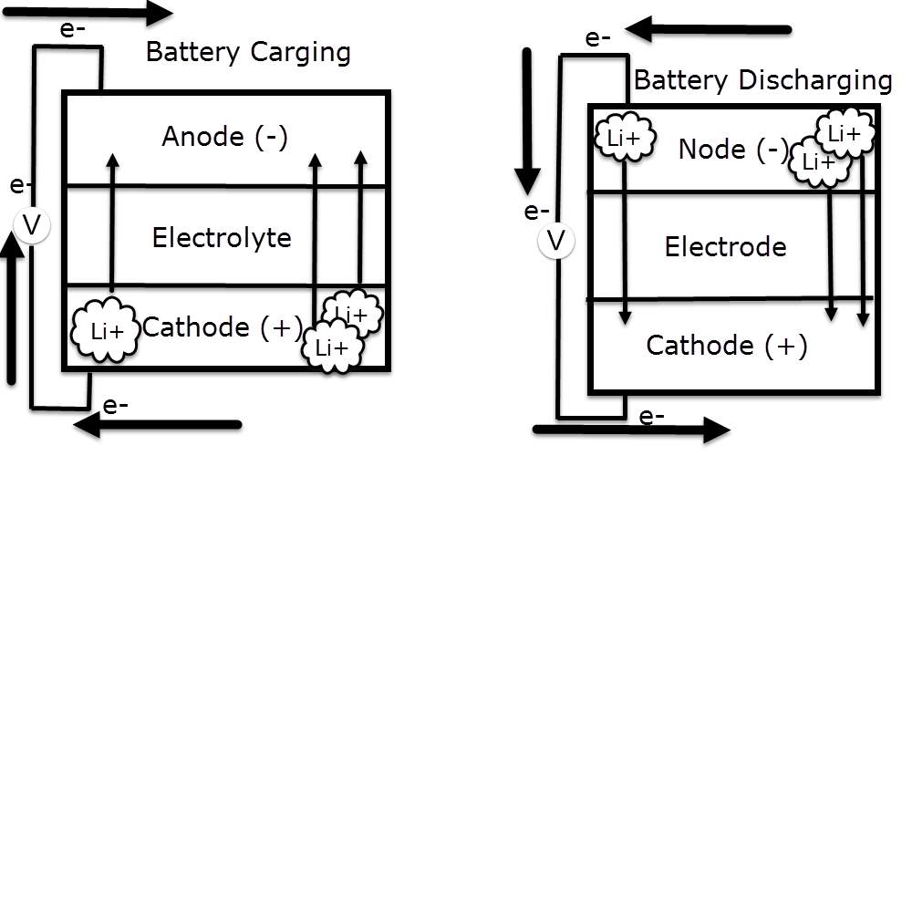
All lithium-ion batteries work in broadly the same way. During charging the battery, the lithium-cobalt oxide, positive electrode loose some of its lithium ions, which move to the negative electrode through the electrolyte, graphite electrode and remain there. The battery store and deliver energy during this process. Notably during discharging the battery, the lithium ions return back to the positive electrode across the electrolyte, producing the energy that powers the battery. During charging and discharging, electrons always flow in the opposite direction to the ions around the exterior circuit. Therefor the electrolyte form an insulating barrier that do not allow the electrons to flow through it.
Notably the movement of this ions (through the electrolyte) and electrons (around the external circuit, in the opposite direction) are interconnected processes, and is either stops so does the other. Losing power is potentially occurs when the battery is discharged completely, which causes ions stop moving through the electrolyte, therefor electrons can’t move though the exterior circuit either. Similarly when switching off the power that charge the battery, the flow of electrons stops and so does the flow of ions.
The battery essentially stops discharging at high rate, bearing in mind it does keep on discharging, at a very slow rate, even with the appliance disconnected.
Advantages of lithium-ion batteries
- Lithium-based batteries are more reliable than older technologies such as nickel-cadmium (NiCdn pronounced “nicad”).
- Don’t suffer from a problem known as the memory effect (where nicad batteries appear to become harder to charge unless they’re discharged fully first).
- Since lithium-ion batteries don’t contain cadmium (a toxic, heavy metal)n they are also better for the environment.
- Although dumping any batteries (full of metals, plastic, and other assorted chemicals) into landfills is never efficient. Compared to heavy-duty rechargeable batteries (such as the lead-acid ones used to start cars), therefor lithium-based batteries are relatively light for the amount of energy they store.
Disadvantages of lithium-ion batteries
- Longer charging time only when used in an electric vehicle that relay only on battery comparing with a gas-powered automobile in couple of minutes. Bearing in mind that these disadvantages are balanced by other advantages, such as greater fuel economy of electric cars and their lack of air pollution (zero emission from the vehicle itself).
- Safety issue, lithium-based batteries potentially catch fire if they’re overcharged or if an internal malfunction causes a short circuit, in both cases, the battery heat up in in thermal runway.
How to solve catch fire
Eventually catching fire or exploding, this problem is solved with a built-in circuit breaker, known as a current interrupt device or CID, which kills the charging current when the voltage reaches a maximum, if the batteries get too hot, or their internal pressure rise up too high.
Who invented lithium-based battery
The chemist John Goodenough include his colleagues Phil Wiseman, Koichi Mizushima, and Phil Jones, were the first people to successfully produce practically valuable lithium-ion power packs, which their experiment took place in Oxford University in 1970s. after publishing their research in 1980, it becomes a commercial technology by Sony who produced the first lithium-ion batteries in early 1990s. Since then they’ve become commonplace.
Technical fact when charging the battery
Recharging the battery or jump starting the battery with booster cables from another battery or vehicle may gets the engine running again, but it will not be for long if the charging system is not producing normal voltage.
Warning: never disconnect a battery cable while the engine is running to test the alternator. The impact of that is damaging the alternator as well as other electronics component, due to high voltage.
Charging system
Alternator charging output
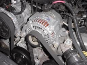
The alternator is the heart of the charging system. It deliver a suitable power to fully charge the battery, and so other electrical circuits when the engine is running. The alternator is mounted on the engine and is belt-driven off the crankshaft pulley by a serpentine belt or v-belt.
Two crucial stages for alternator to charge the battery
- Rectifier stage
The alternator produces alternating current (AC), which is converted to direct current (DC) by six diode rectifier, which is usually located inside the back of the unit.
Diodes only pass current in one direction, which how they convert AC current to DC.
Three positive diodes control the positive side of the AC sine wave, while three negative diodes control the negative side.
The alternator charging output increases in proportion to the electrical load on the charging system and engine speed. Output is low at idle and increases with revolution per minute (RPM). Maximum output typically achieved at speeds above 2,500 RPM.
- Alternator voltage regulator
Charging output of the alternator is controlled by regulator, which may be mounted inside or on the back of the alternator (internally regulated), or somewhere else under the bonnet (externally regulated).
- On most newer vehicles, the power train control module (PCM) regulates charging output.
- On older vehicles, the voltage regulator was electro-mechanical and used magnetic contacts to control the charging output of the alternator.
Since 1980s, most voltage regulators are solid-state electronic and use transistors to control charging output.
The actual output voltage produced by the alternator will vary depending on temperature and load, but will typically be about 1-1/2 to 2 volts higher than battery voltage. At idle, charging systems will deliver approximately 13.8 to 14.3 volts while no load is consuming power. Although some may charge at a slightly higher voltage depending on
- Temperature
- engine RPM
- type of battery
- battery’s state of charge //put figure number, see figure…//
 |
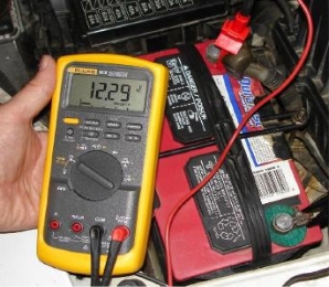 |
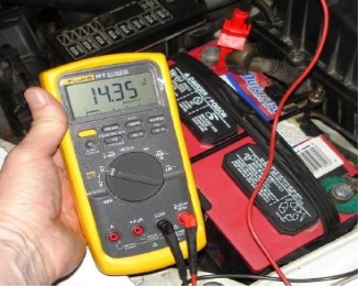
This can be measured by connecting the positive (+) and negative (-) test leads of voltmeter to the battery posts while the engine is running.
The left photo above shows normal alternator charging voltage with the engine idling. The above photo at the right low charging voltage with the engine idling. A low reading indicates the charging system is not generating enough voltage to keep the battery charged or to meet the vehicle’s electrical needs.
Measuring alternator outputs
- Alternator voltage
The exact charging voltage will varies according to the battery’s state of charge, load on the vehicle’s electrical system, and temperature.
The lower the temperature the higher the charging voltage, and the higher temperature the lower the charging voltage. Bearing in mind the normal charging voltage on a typical application might be 13.9 to 15.1 volts at 77F degrees. But at 20Fdegrees below zero, the charging voltage might jump as high 14.9 to 15.8 volts for short period of time. Experimentally on hot engine on a hot day, the normal charging voltage might drop to 13.5 to 14.3 volts.
- Alternator amperage output
Alternator amperage is how much current the alternator generate at a specified voltage and speed. In early years an 80 amp alternator was considered a high output unit. Most late model alternator produce 120 to 155 amps or more.
Current output increases with engine speed, from around 20 to 50 amps at idle up to the unit’s maximum output at 2.500 RPM or higher.
Measuring the alternator charging output can be determine using an inductive amp wire placed at the BAT (B+) pole that connects to the alternator. Alternator power rating can also be given in Watts (which volts times amps).
Alternators failures
- Alternator overheating
Since the alternator located near the engine under the bonnet, the temperature of the alternator is increasing, alongside high electrical loads create even more heat. To reduce the heat, alternator associated with an internal and /external fan that pulls the housing to help cool the rotor (rating part inside alternator), and the stator (the stationary field coils or windings that surround the rotor). Some high output units have two fans ti increase cooling.
Therefor if the alternator is working hard under a heavy load at low RPM, there may not be enough cooling to prevent the unit from overheating. The alternator becomes defective by damaging the windings and/or wiring connections within the unit, due to the excessive heat. This tends to be more of problem on vehicles where the location of the alternator restricts airflow and cooling.
- poor alternator wiring connections
The alternator may experience working under high pressure if battery cables are not connected properly. A poor connection causes a voltage drop across the connection, due to increasing of the resistance. This, in turn, decrease the current flowing through the charging circuit.
The electrical system after all, just a big series of loops that carry current from the charging system to the battery, and from the battery to all of the vehicle’s electrical accessories and electronics. Notably the return path is usually the vehicle body, which services as the main ground circuit for almost everything. All the power supply and ground connections must therefore be in excellent condition to minimize resistance and the load on the charging system. In fact, poor ground connections are often overlooked cause of flow charging output and alternator failure.
- Alternator diode failures
One the most common causes of charging problems is the failure of one or more diodes in the alternator (rectifier part). When engine is running, charging current from the alternator flows through the diode trio (rectifying diodes where each negative diode is paired with a positive diode), via the BAT (B+) connection on the back of the alternator. Al little current also flows through the charging light indicator circuit. On GM alternators the indicator light circuit is terminal (1). On European alternators, the indicator light circuit is usually called (61 or D+). On Asian alternators, it is usually labelled (L). During charging cycle of the alternator, the diode trio deliver a voltage to the indicator light ground side. This offsets the battery voltage reaches the light positive side, so when starting the engine the light go out. Charging system warning light turns on, when the flow from the positive side of light circuitry, which usually occur when the alternator not charging.
If one of the diodes fails, it may cause the charging system indicator to glow dimly. If two or more diodes fail, the light becomes brighter. At the same time, the feedback current from the diode trio will reduce the alternator ability to produce current. So more diodes that fail, the less power the alternator will generate.
Alternator tests
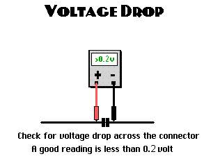
Alternator circuit voltage drop tests
With the engine idling, touch one test lead of the voltmeter to the battery positive (+) post, and the other test lead to the battery (-) terminal on the alternator. Ideally, the voltmeter should detect volts below 0.2. A high resistance within the circuit display indicate when the voltage reading is higher than 0.2 volts, causing a voltage drop in the wiring circuit. Check all the wiring connections, and ensure the terminal connectors on the ends of the wires are clean and tight.
Extra facts that affect alternator performance
Alternator vibration
Loose alternator mounting bolts and can cause vibration which may damage the alternator. Also the vibration can indicate a defective belt tensioner If the alternator bearing or diode is defective, which lead the current to flow to the opposite direction A cycling buzzing noise may occurs.

 Battery modelling put refrence
 Establishing a battery model is not an easy process regarding to the complexity of battery’s electrochemical mechanisms of. From the perspective of chemical characteristics, (Scrosati and Grache), declared voltage-to-capacity profiles of many Li/Li+ materials. For instance, LiFePO4 is characterized by prolonged flat trend when charging, while the voltage profiles of LiMn3O4 and LiCo1/3Mn2/3O2 gradually increment without a flat region. A generic model for a battery family expermently not performing well for general applications. Recently, battery modelling for state of charge (SOC) declaration is commonly improved from various equivalent circuit such as (RC network) models, which are distinct comparing to other material characteristics and accuracy requirements. (Cheng and tremlay) determined the integrated generic battery model by MATLAB. However, the generic model during charge and discharge cycles is depend on the presumption that the internal resistance is constant. Thus, the accuracy of this model is subject to challenge. While taking into account the State of Health (SOH) estimation, the battery degradation model based on capacity fade was simulated and built. These model parameters were predominantly achieved in terms of the physical characteristics of the specific anode and cathode. However, the influencing factors that affect stationary models are significant such as current load, environment temperature and discharge, resulting, the impact on these type of models is poor accuracy in a dynamic environment. Therefore, model selection is always relay on in a battery management system (BMS).
Practical
The simplest method of monitoring batteries is using analogue circuit, notably these type of circuits consist only on an analogue component connected together within a soldering board. Bearing in mind these conventional type of monitoring are very simple, and not efficient as it will only display a clue of light glowing or for instance just a relay stopping action, when amount of voltage is exceeded.
Since the lithium battery is very sensitive to the temperature and the amount of volts and current, lead to significant demand of displaying the aimed battery parameters status in very accurate way, (display the detected parameters as a digital data within LCD screen). therefor the best suitable engineering monitoring method for this case is using microcontroller (MCU).
Microcontroller is a smart electronic chip that contains many electronics component, those component are forming together an integrated smart circuit (small computer), as it contains CPUs (processor cores) alongside a programmable pins (input/output) as well as memory. The functionality of these type of circuits depends on two main parts, a hardware part, and software part (using a code written in an engineering language to control this circuit). Notably these smart circuit are very efficient and modern technology, the first microcontroller were launched in 1970s by Intel 4004 as a 4-bits chip, now days there are a much more flexible chips that provided with much more bits that suite life development demand. Almost all of the devices and machines that produced in the last 30 years are depends on these smart chips.
//What is the different between the raspberry pi and Arduino //
Raspberry pi
The raspberry pi is a very cheap flex able computing platform, mainly used to run multiple tasks in the same time, which can one by programing its digital pins with a high level engineering language.

Arduino
Is a simple microcontroller that can run one particular program the time, and repeating running the programme over and over as long as the condition is valid. By programing it through it analogue and digital pins, using one of embedded programming language.
Since the signal that the sensors reads for the battery are analogue, and the computer does not recognise analogue signals, therefor raspberry pi is not suitable for this design, as it is not contains any analogue pins to read. Significantly the Arduino does have analogue and digital pins, which making the best choice for this design.
Principle of sensors operation
Input impedance
DC voltage gauged by a digital multimeter, if the input impedance reading is 10MΩ or more, it indicate that there is at least 10 MΩ resistance between the two multimeter tests.
Detecting the voltage across a component within a circuit using multimeter with an input impedance of 10M ohms, is identical to connecting a 10M ohm resistor across the component.
If a voltmeter has a low input impedance, say 10KΩ and a voltage across a 10KΩ resistor is being measured, the multimeter is effectively changing the resistor value to 5 KΩ (two 10 KΩ resistors in parallel = 5K resistor). The multimeter, therefore, has changed the circuit and possibly the voltage being measured.
So an elevated input impedance is suitable in this voltage divider circuit when the impedance of this voltmeter has an effect on the circuit being measured. Therefore, an elevated input impedance device will generally be affected with noise or interference (EMI) comparing with a low input impedance device.
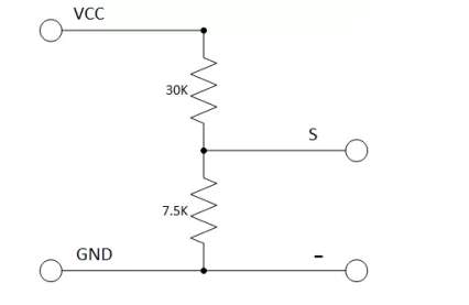
Voltage divider circuit
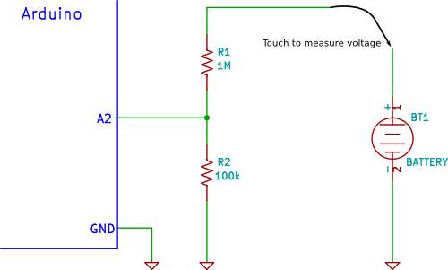
A usual voltage divider circuit depend on two resistors connected in series, according to ohm’s law, this circuitry will reduce the voltage to suit the Arduino analogue input.
The circuit shown will divide the input voltage by 11(from the battery as the example input voltage being measured). The circuit with the particular values shown has an input impedance of 110MΩ + 100KΩ = 1.1 MΩ and it is suitable for measuring DC voltage up to about 50V.
Arduino voltage divider
It is possible that the sensors to share the ground pin with Arduino GND pin when Arduino powered exterior power supply (battery power).
Input protection
When detecting a low voltage in the circuit diagram above, for instance 5V, 9V or 12V, the selected resistors value of the voltage divider circuitry protect the circuitry from any over-voltage.so for instance if a high voltage of 40V is detected, the Arduino remains safe.
Arduino data sheet indicate that it possibly be defective if the voltage reaches 55V and higher. Therefor the principle of the resistors network that form a voltage divider, is identical to input voltage divider of 11V, so when dividing the maximum voltage over the input voltage divider gives the appropriate Arduino typical voltage,
5511 = 5V
. so in summery measuring 55V, the Arduino detect this value as a 5V.
Understanding and using this fundamental of voltage divider, is to avoid using sensors to detect the aimed battery parameters (voltage, current and temperature).
Notably it is exactly the same principle that those sensor are using, but for more accuracy the manufactured sensors are preferred in this design
Calibrating the Arduino and the circuit
Using a maximum of 1% tolerance resistance, and precise voltage reference for the Arduino is crucial for high accurate reading, since the application that going to apply to (Lithium-ion) is very sensitive to any changes on these readings.
In fact there is another to achieve a high accuracy reading, is by calibrate the circuitry. The calibration can be done within the Arduino sketch code, after reading the actual value of Arduino reference voltage and the actual reading the voltage divider circuitry.
The microrcontroller used is ATmega
This design consist on two parts
Hardware part
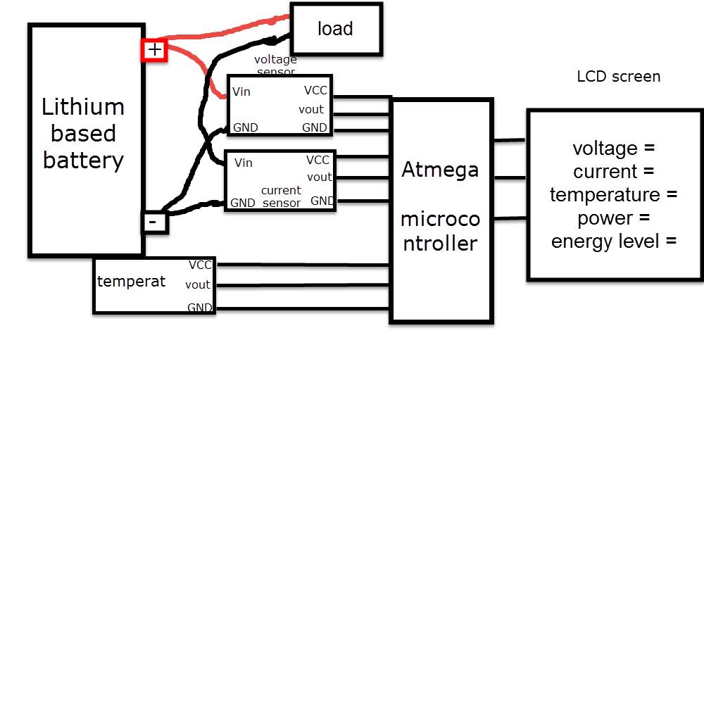
Based on the study of the lithium battery characteristic within this report, the major parameters of the battery that need to be monitored are the following
- Voltage
- Current
- Temperature
- Power consumption
- Battery level (energy percentage)
Sensors needed for this design
| Volte sensor | Current sensor | Temperature sensor |
Detecting battery’s voltage, current and temperature
Arduino analogue inputs can be used to measure DC voltage between 0 to 5V (on Arduino such as the Arduino Uno when using the standard 5V analogue reference voltage). The range over which the Arduino can measure voltage can be increased by using two resistors to create a voltage divider. The voltage divider decreases the measured voltage to suitable to Arduino analogue inputs. the real voltage being measured is calculated via Arduino sketch code This method allows to measure a voltage higher than 5V.
Principle of sensors operation

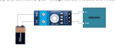
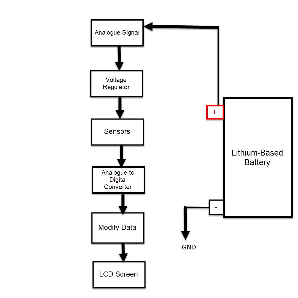
The voltage sensor has two main sides of connections, the input side with two connections (GND and VCC), are connected to the battery poles. The GND connector is connected to the battery negative pole (B -), and he VCC connector is connected to the battery positive pole (B +). While the other side of the sensor (output), contains three connections, (S, + and -), where the (S) connector is connected to the analogue input of the Arduino, and the (+), is neglected as there is no need for it and the (-) connector is connected to the Arduino ground pin.
Therefor the sensor detect the battery voltage through the (VCC) connector, and deliver it the microcontroller via (S) connector after modifying this voltage using the voltage divider method. Since the battery voltage is an analogue data, and the computer, as well as the microcontroller does not recognise these type of data, therefor the microcontroller convert this signal to a digital form through the analogue to digital converter, and display this data on the LCD screen, associated with this design which can be comprehended with the software part, that include the functions routine.
Current sensor
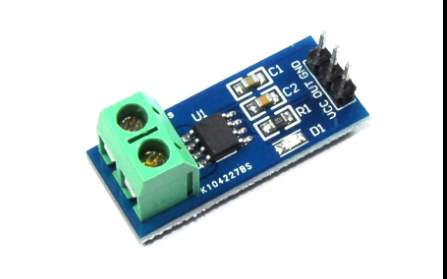
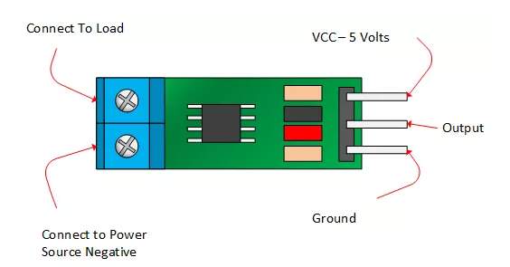
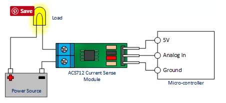
The ACS712 current sensor consist on Alegro ACS712ELC chip, which is provide scale values of 5A, 20 and 30. The one used in this design is with 30A for more safety.
This sensor has two sides on connections input and output, where the input side is associated with two connectors, one side is connected to the load, while the other side connected to the battery ground side. Also the output side of this sensor consist on three connectors (VCC, Vout and GND), where the Vout is connected to the microcontroller analogue pin, the VCC is connected to the microcontroller power and the GND connected to the microcontroller ground pin.
Therefor the sensor detect the battery current vlaue through the input connector, and deliver it the microcontroller via (Vout) connector after modifying this current using the voltage divider method. Since the battery current is an analogue data, and the computer, as well as the microcontroller does not recognise these type of data, therefor the microcontroller convert this signal to a digital form through the analogue to digital converter, and display this data on the LCD screen, associated with this design which can be comprehended with the software part, that include the functions routine.
Temperature sensor
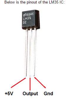
The major essence of functionality of the LM35 temperature sensor is converting the between Fahrenheit and Celsius, using these formulas
F
°= C
° ×1.8 + 32 for Fahrenheit
C
°= (F
°-32)
÷1.8 for Celsius
This sensor has three legs connectors (VCC, output and GND), where the sensor itself will be attached to the battery body, the VCC connected to the power supply
(B +) and the GND connected to the battery negative side (B -). The sensor sense the battery temperature and convert it to voltage value that will be transferred to the microcontroller, this signal is an analogue data, therefor the microcontroller convert it to a digital form and display it on the LCD screen.
Discussion
To monitor a particular system. It is crucial to study the aimed system component beside it characteristic, by doing so, it is possible to determine the system parameters that change it behaviour in a varying conditions, which, will clarify the exact parameters need to be targeted within this monitoring process.
Based on the above case study, the cars electric system consist on three main electric circuits.
- Starting and charging circuit, this circuit is a closed loop system that becomes active as soon as the switch is turned on. When the switch at starting position, current flows from the battery to the starter, where this current amplified through coils and becomes suitable to start the engine through the start plugs. Once the engine turned on, the alternator start to rotate and generate electric current, this current is a AC current and it is varying due to the speed variation, therefore AC current turn to be a DC current by the rectifier, and regulated by the regulator and back to charge the battery.
- Load power supply circuit, the power for this circuit is supplied from the alternator when the engine is on, otherwise the battery deliver the power needed.
- Monitoring circuit, this circuit is connect directly to the battery that detect battery status.
Choosing a suitable method to proceed with this project, should also be based on the following
- Detect the targeted parameters, and display the changing behaviour under different conditions at all time.
- Accurate and easy to maintain
- Cheap and economic
Since the existing signals in real, world such as voltage, current and temperature are an analogue signals. In other hand those signals are continuous in amplitude and time. While the computer and microcontroller does not recognise those type of data, converting those signals to digital data (discrete in amplitude and time) is required.
By analysis the available monitoring methods, the Raspberry pi, is rejected as it does not contain (AD converter). Thus, the Arduino technology used, notably adding a secondary circuit (AD convertor) to Raspberry pi is possible, but it the cost will increase, and so the power consumption.
Using an independent power supply connectors for voltage, current and temperature sensors in recommended, due to the effect of each sensor to the other, which will reduce the accuracy of this design. Thus, an individual voltage stabiliser is required for each sensor.
Conclusion
In this report clarified, that just as an individual cell may not behave uniformly under high current conditions, so an entire battery pack is also susceptible to non-uniform currents flowing through individual cells when there are parallel strings present in the pack. This is particularly acute under high-C charge or discharge conditions.
There are some clear implications for this design of the battery management and the monitoring systems in this type of parallel arrangement. First the battery management system (BMS) voltage sensing must be located at the side of module where the voltage drop is expected to be worst. Second, an active balancing BMS may need to include a delay before active balancing in order to allow time for passive balancing current to flow within the pack. As batteries are the core energy sources in Electric Vehicle Systems (EVs) and Hybrid Electric Vehicle Systems (HVs) as well as the Formula Student Vehicle Systems (FSVs), their performance greatly impacts the saleability of the vehicles that relay on Lithium-based battery.
Therefore, manufacturer’s interest increasing in these two aspects, battery technology and BMSs. Chemical reactions in the battery are subject to operating conditions, and hence, the degradation of a battery may vary in different environments. Developing a comprehensive and mature BMS is critical for manufactures who would like to increase the market share of their products. The major concerns of BMSs were discussed in this paper. Which include battery state evaluation, modelling and cell balancing, wherein the evaluation methodologies of batteries status were viewed as the crucial issue. Thus, related work on the System on-chip (SOC), State of Health (SOH) and State of Longevity (SOL) of batteries were reviewed with comparisons.
A BMS framework was proposed to deal with the deficiencies of current BMSs in both research and commercial products.
Cite This Work
To export a reference to this article please select a referencing stye below:
Related Services
View all


Related Content
All TagsContent relating to: "Automotive"
The Automotive industry concerns itself with the design, production, and selling of motor vehicles, such as cars, vans, and motorcycles, and is home to many multi-billion pound companies.
Related Articles

DMCA / Removal Request
If you are the original writer of this dissertation and no longer wish to have your work published on the UKDiss.com website then please: