Appraisal of Formwork Types
Info: 11416 words (46 pages) Dissertation
Published: 12th Nov 2021
Tagged: ConstructionDesign
Chapter 1: Introduction
1.0 Introduction
The subject for this dissertation is the appraisal of formwork types and design and to identify the advantages of innovative materials, systems and design.
The types of formwork will include the material of the formwork such as steel, plastic and wood, and how the material affects strength, durability and other characteristics. The techniques used to construct and erect the formwork, such as traditional on site fabricated formwork, traditionally timber waling’s, bearers and ply board facings as opposed to modular prefabricated sections which can be joined with ease. Also the type of formwork can be either temporary as commonly found, where it is striped when concrete is cured to an adequate strength, or permanent formwork which becomes part of the structure. Permanent formwork is becoming increasingly popular for its improved health and safety and reduced labour and time consumption.
The Design of Formwork covers both the architectural and structural aspects of formwork design, and how it can affect the cost, completion time, quality of product, workability and health and safety. It also covers common applications and structures where formwork is used and why that specific formwork is fit for purpose.
1.1 Historical background
Some examples of concrete like material using materials to form the shape of the structure date as far back the Roman Empire, the most prominent example being the Pantheon which is believed to have constructed between 118 – 128 AD. Formwork examples were also used in the construction of masonry, to create complex structures such as arches and domes. As masonry and concrete materials are good in compression and not in tension these shapes were good ways of dissipating tension through arch action.
With the industrial revolution and the need for fast construction of infrastructure, formwork started to develop to keep up with demand. Prefabricated modular panels were manufactured to increase productivity, and in 1985 Peri released a modular panel with only a few different components and only one connecting part.
Four years later they produced the ACS self-climbing system, referred to as slip form which allows the formwork to climb using hydraulics, meaning the formwork would not have to be fully disassembled and lifted mechanically by cranes to the next lift.
From the 1990’s innovation in formwork has continued to develop, with the improvement of the existing systems available and the adaptation of newer fit for purpose systems such as table formwork developed into tunnel formwork, allowing walls to be cast at the same time as floors. The introduction of new software to increase the design productivity, meaning design changes can be quick and accurate.
1.2 Overview of methodology
After carrying out a literature search which covered both formwork types and design, I broke these down into further sub categories, such as materials, techniques and structures. With these categories I searched for literature which related to both them and formwork, through search engines and library catalogues.
1.3 Issues to be investigated
As innovation in construction develops the techniques and systems used to construct infrastructure follow. It is important that contractors keep up with this development so that they have the ability to tender for and construct these structures.
In the design of formwork, a contractor will have to select what formwork will be necessary to construct the designed structure. This will depend on cost, time, quality and health and safety. This selection can be timely and cause delays, and sometimes the wrong decision can be made.
1.4 Aim
The aim of this project is to identify the advantages of innovation in formwork types and design. It identifies where alternative methods of construction, such as alternative formwork types and design can be used to improve safety, productivity and quality.
1.5 Formulating objectives
To identify relevant objectives using the literature search, I created a number of mind maps. These mind maps started with titles of literature I had studied and was assessed in three different categories; issues, topics and ideas. From these categories I produced the following statements.
Issues
- Selection of a fit for purpose formwork system to increase productivity.
- Selection of a fit for purpose formwork system to improve concrete properties.
- Selection of a fit for purpose formwork system to improve curing times.
Topics
- Effect of formwork type and design on placement and compaction.
- Effect of formwork type and design on concrete finish/aesthetics
- Effect of formwork type and design on health and safety
Ideas
- Improving the selection of formwork protocol.
- Standardising the selection of formwork protocol.
- Analysing the benefits of innovative formwork
From these categories I have concluded the following objectives:
Chapter 3: Innovation in concrete
To discuss the innovation of products, uses and forms developed for the construction of modern designs:
- Concrete products with properties such as high-strength, low carbon and self-compaction.
- Techniques and manufacturing of products for improved product quality and aesthetics.
Chapter 4: An innovative material in formwork
From the findings in Chapter 3 an innovative material will be selected for further analysis. I will evaluate this material against traditional materials and analyse its benefits.
Chapter 5: Structured interview – formwork types and design
A structured interview with colleagues experienced in the use of formwork to identify common themes that may arise whilst selecting and using formwork systems.
Chapter 6: Resolving common issues through innovation
From the findings in Chapter 5 common themes will be addressed with the use of innovation.
Chapter 2: Literature review
2.0 Introduction
This chapter reviews the literature which I have collected for the basis of my research. This literature covers all the topics outlined in the issues to be investigated.
2.1 General literature
There are many independent bodies that provide literature for the construction industry and some specifically for concrete. These bodies cover many topics, but most frequently look at the progression of sustainability and innovation, by conducting and analysing research and case studies.
The Building Research Establishment (BRE) have recently (2007) published an informative leaflet which covers ‘formwork for modern efficient concrete construction’ by R. Rupasinghe and É. Nolan. This considers all popular modern formwork and which structural elements they are applied too. The Concrete Society publishes many technical reports covering sustainability and innovation of concrete. There are three publications from E. Toogood, Senior Architect at the Concrete Society. I have found them to provide lots of information on modern formwork, they are; formwork and finishes, specifying sustainable concrete and Innovation in concrete. I then attended a lecture from E. Toogood on innovation in concrete to get an up to date look at what was happening in industry.
The Royal Institute of British Architects (RIBA) have published a book called ‘Architectural in-situ concrete’ by D. Bennett. Although it is an architectural book it covers lots of technical aspects of concrete and formwork practise and design. It talks about the way new techniques are enabling concrete to be such high quality that it offers highly desirable aesthetics it terms of finish and shape. ‘Formwork for concrete structures’ covers formwork more from an
engineering and contractors point of view. Written by two American engineers R. L. Peurifoy and G. D. Oberlender it looks at the design of temporary structures such as formwork during construction. Before it covers all technical aspects of formwork it covers the ‘economy’ of formwork in terms of cost, time and quality.
A technical report which is collaboration between The Construction Industry Research and Information Association (CIRIA) and the Concrete Society, managed by R Mc Clelland and P Pallett called ‘permanent formwork in construction’. Is an informative text which highlights advantages of permanent formwork in terms of time, cost, quality and safety.
2.2 Codes of practice
BS 5975 Code of practice for temporary works procedures and the permissible stress design of falsework. This gives guidance on all aspects of falsework and relevant formwork. It includes information on specifying, constructing and dismantling of falsework. This guidance can be used for class A falsework in BS EN 12812:2004. The design of Class A formwork is specifically excluded from BS EN 12812:2004, so that there is one clear methodology put in place. BS EN 12812 Falsework — Performance requirements and general design is a European standard that specifies performance requirements and limit state design methods for two design class A and B of falsework. It does not provide guidance on site activities and standard products that may be used. Caution should be taken when using this document with BS 5975 as the design methodology is significantly different.
BS 8110 Structural use of concrete – Code of practice for design and construction provides guidance for structural concrete in buildings and structures. It assumes that all structural elements are concrete. It includes recommendations for formwork design, construction and dismantling for the purposes of safety, quality and efficiency. BS 8500 Concrete is a 2 part document which specifies concrete and constituent materials. It outlines properties of different concrete specifications and how they act during and after placement. This is important as a concrete and formwork system will be designed together to work efficiently.
2.3 Guidance manuals and notes
A book published by The Concrete Society in conjunction with the Institution of Structural Engineers. Formwork: A guide to good practise looks at both the practical and engineering side of formwork. It provides guidance on design, specification and construction; and includes worked examples of formwork design. The Concrete Centre have published a book called Designing for safer concrete structures by J. Carpenter; which looks more at safety and good management during design and construction.
CIRIA report R108 Concrete pressure on formwork by C.A. Clear and T.A. Harrison covers all elements that effect pressure on formwork. It covers the most used cements and admixtures, rate and height of concrete placement and how they may affect the design of formwork due to the pressure placed on it.
2.4 Research papers
From my general literature search I identified controlled permeability formwork (CPF) as an interesting concept. From a further search I have found two Research papers that study the use of CPF.
Cuicui Chena and Jianzhong Liu have researched the effect of CPF on the improvement of concrete performance. They look at its use in order to prevent the corrosion of steel reinforcement through a denser, less permeable surface. The denser surface is a result of the CPF’s ability to allow air and water to drain through it, minimizing air voids.
M J McCarthy and A Wibowo use previous information from the university of Dundee to quantify the practical issues for CPF use in concrete construction. This paper is more focused on the effects of different materials, applications and site conditions when using CPF liner.
2.5 Summary
The literature review has identified the most common independent bodies which manage the development of concrete. They research, analyse and review the activity in the construction industry to provide useful information on innovative and established materials and techniques. The codes of practise that I have found to be relevant are British Standards, and will have been put through rigorous scrutiny before being released. They are also regularly looked at and amended due to a changing work environment. In the guidance part of the review I found that the independent bodies would use their depth of knowledge to provide guidance. This is usually but not restricted to good practise, with the exception of some information on design considerations.
Formwork accounts for a large cost of the construction of superstructures, and when considered with the literature available for design and types of superstructure, there is a lot more. I feel that as formwork design is usually undertaken through a subcontractor and not by design team members it is neglected in terms of professional development. The future of efficient formwork relies on the restructuring and development of the construction industry. Hopefully the progression of BIM will contribute to this, and it will be given more consideration in terms of CDM regulations during the design phase.
Chapter 3: Innovation in Concrete
3.0 Introduction
I attended a lecture through the ICE held by the concrete centre to get an up to date look at what innovative materials and techniques were becoming available and more popular in industry. The lecture was called innovation in concrete and was delivered by the concrete centre Senior Architect Elaine Toogood.
3.1 Aim
Identify where innovative materials can be used in relation to formwork type and design. Identify a specific innovative material for further research.
3.2 Innovation in concrete lecture
The lecture began by talking about ordinary portland cement (OPC) replacements, and how they can be utilised to achieve a specified sustainable concrete. The main replacements that are currently well used are ground granulated blast-furnace slag (GGBS) and pulverised fuel ash (PFA). These two are covered up to the British Standard BS EN 174-1 cement for use in concrete and Eurocode 2: Design of concrete structures.
Other similar cement replacement products are not currently covered under British Standards and for this reason they are not specified where they would be the most appropriate material. These materials are usually developed under product approval specification (PAS) documents which are flexible and allow all organisations to contribute to its development. After two years a PAS document will be reviewed and a decision will be made on whether it will be brought forward to become a British Standard. Whilst a material is still at the PAS it will not be used for structural concrete as it is not yet recognised as an industry standard.
It is important for formwork that the characteristics of the concrete that is placed is acceptable in terms of the designed temporary structure. Designing formwork for large pressures can mean high cost in resources, labour and management. By specifying a suitable concrete we are able to design the formwork more efficiently whilst still achieving the correct strength, durability and other important properties.
Various formwork materials are currently being developed in industry, most of these designed for architectural purposes. A recent ingenuity in formwork facing is the use of polypropylene. Birch or Beech plywood is covered with a polypropylene film which helps to achieve a high quality finish and high re-usage. It is also easier to strip the face from casted concrete and clean, leaving a uniform colour and finish.
Controlled Permeability Formwork (CPF) liner is fixed to the formwork facing material; it is a polypropylene material with a filter layer and a free draining layer. CPF Liner creates a denser concrete at its surface. This is achieved by allowing excess water and air to escape via the permeable formwork liner this reduces blowholes significantly and other surface blemishes. This denser surface creates a more durable concrete and is more resilient to chloride attack and ingress of water, making it ideal for marine applications.
Insulated Concrete formwork (ICF) is a system for constructing walls quickly with high insulation. It uses an interlocking lightweight hollow block to create a form which can be mass filled with concrete. The block is made from expanded polystyrene and integrated steel or plastic ties to form the void. ICF allows walls to be built at speed with a U value of around 0.2. The use of ICF is low skilled and reduces other tasks associated with traditional blockwork wall construction. A comparable cost between traditional wall construction and ICF is very similar yet ICF is quicker and offers better thermal properties.
3.3 Conclusion
From further research and literature review I find the use of controlled permeability formwork can be very useful. I have selected this as the material I will further analyse against traditional materials as outlined in my introduction. In addition I will also include further research into cement replacement in association with this material.
Chapter 4: An innovative material in formwork – The effect of permeable formwork (CPF liner) on concrete
4.0 Introduction
In this chapter the characteristics of different formwork facing materials will be discussed. From this discussion I will build a thesis on how CPF liner will affect the durability of different mixes of concrete relevant to placement of common structural concrete applications. I will then go on to test materials to prove my theories/thesis and outline any benefits, and the feasibility of these benefits in specific applications.
4.1 Abstract
To test the effect of permeable formwork (CPF liner) on concrete, I took concrete specimens using two designed concrete mixes. These specimens were then tested on regular vision surface morphology, absorption of water, surface hardness and compressive strength. CPF liner will be used with the intention of creating a denser and stronger surface which will inhibit water and chloride from permeating into the concrete. This will increase the durability of the concrete which will in effect the strength.
4.2 Aim
Assess the concrete durability of medium density overlay panel (MDO) and controlled permeability formwork liner (CPF).
4.3 Objectives
- The objective of this experiment is to confirm the theory that the effect of CPF liner will increase the durability of concrete.
- To identify the effect that increased durability has on concrete strength.
- To identify the effect portland cement replacement materials such as pulverised fly ash (PFA) have on durability of concrete.
4.4 Theory
Schwinn hammer rebound test
The rebound hammer test is used to find the surface hardness of the concrete. It measures the concretes elastic properties by using a spring loaded mass to impact the surface; the rebound of the instrument gives the surface hardness.
Regular visual inspection of surface morphology
This is a visual inspection of blowholes that exceed 600µm in diameter. The CPF liner should reduce the blowholes by allowing air to be released at the formwork face. The amount of blowholes is directly related to the permeability of the surface of concrete.
Water absorption
Finding the percentage of absorbed water from immersion in a curing tank and then drying will give an indication on what effect water will have on the concrete. However, it does not directly relate to permeability which gives an indicator of concrete durability. As I have no way of testing permeability, water absorption will be used to show the difference in water absorption in different formwork liners. This will identify that CPF liners create a concrete surface less likely to absorb water which in affect will lower effects of freeze and thawing and mean a more durable concrete.
Water absorption (%) =
Msat – MdryMdry×100
Compressive strength
Using 10cm3 cube moulds a testing specimen is cast. The compressive strength is then measured at 1, 8 and 28 days using a compression testing machine. This applies a load of 140kg/cm2 per minute until the specimen fails. This gives the characteristic compressive strength for the concrete
4.5 Testing procedure
Using weighing scales the above quantities of materials were weighed, and mixed in a rotating pan mixer. The slump is then tested with a slump cone to check the consistency of the mixes. The 0.1m3 moulds are then filled in 50mm layers and compacted using 25 tamps of a 25mm square tamping rod. The 0.3m x 0.2m x 0.1m moulds are also filled in 50mm layers but are tamped 75 times per layer as the tamping surface is three times the area of the 0.1m3 specimens. The CPF lined moulds have a reduced volume of 0.094m3. The specimens are then left to cure at 20oC overnight at a relative humidity of 100% and then striped at 24 hours. The first four cubes are tested for compressive strength at 1 day, and all other cubes are placed in curing tank at 20oC at a relative humidity of 95%. Four more cubes are then tested at 14 and 28 days respectively. The 0.3m x 0.2m x 0.1m specimens are weighed and placed in the curing tank for 7 days they are then weighed as saturated and placed in an oven at 100oC for 24 hours and then weighed as dry. At 28 days they are tested for surface hardness using a Schwinn rebound hammer.
Concrete design mixes – I have chosen to use a structural concrete for this experiment as CPF liner would be used in any structures that would be subject to constant contact with water. The designated mix chosen is structural C30 mix, one mix using Cem I and the other using Cem IIa-v which uses 20% PFA as its main addition. The Cem IIa-v allows a slightly lower w/c ratio. Full mix design form is in shown in Appendix 1.
|
Table 1 – Mix design quantities per m3 – C30/35, S3, max 20mm aggregate |
||
| Cem I (kg) | Cem IIa-v (kg) | |
| Cement | 415 | 364 |
| Main addition – PFA | – | 91 |
| Water | 195 | 180 |
| Fine aggregate | 592 | 589 |
| Coarse aggregate 20mm | 1200 | 1196 |
Risk assessment
See Appendix 2 for Risk Assessment
Apparatus
6no of plastic 0.1m3 moulds
6no of steel 0.1m3 CPF lined steel moulds with a reduced effective volume of 0.095m3
2no of 0.3m x 0.2m x 0.1m MDO moulds with release agent applied to form face
2no of 0.3m x 0.2m x 0.1m CPF lined MDO moulds
Weighing scales
Rotating pan mixer
Slump cone kit
Curing tank
Schwinn Rebound Hammer
Oven
Compression testing frame
Various hand tool
4.6 Results and discussion
Schwinn hammer rebound test
Table 2 – Schwinn hammer rebound test results at 28 days
| Average | Compressive | Compressive | |
| dispersion | strength, kg/cm2 | strength, N/mm2 | |
| Cem I – MDO | 39.16 | 450 | 44.15 |
| Cem I – CPF | 43.67 | 540 | 52.97 |
| Cem II – MDO | 44.5 | 550 | 53.96 |
| Cem II – CPF | 47.33 | 590 | 57.88 |
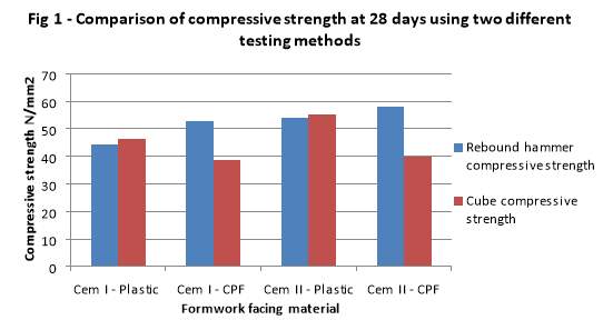
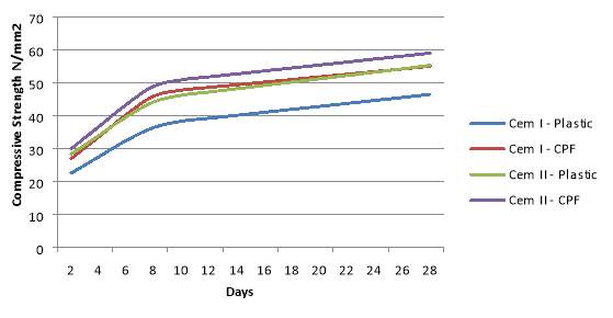
The Schwinn hammer rebound results indicate a higher compressive strength than in the cube crushing strength results for CPF, whereas for the plastic mould the strength is comparatively similar as shown in Fig 1. I believe this may be due to the geometry of the finished CPF concrete specimens. When the CPF specimens were striped they did not produce a totally equal cube and had a small lip where the CPF liner was not joined very well. It is important that cube moulds are the correct dimensions and are calibrated regularly so as to reduce the chance of the specimen failing at a reduced load.
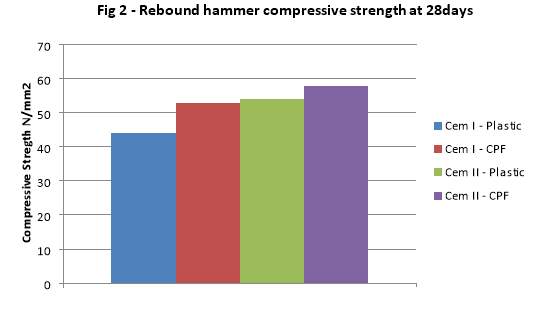
The strength of the CPF lined blocks was 19.98% stronger than the MDO lined blocks for the CEM I mix and 7.26% stronger in the CEM II mix as shown in Fig 2. This shows that the liner creates a denser and harder surface by letting water and air drain through it. By creating a harder surface this will increase the durability of the concrete because it will be less susceptible to chemical attack, freeze/thaw effect and surface abrasions. This is evidence that objective 1 of this experiment to confirm that the use of CPF liner will increase the durability of concrete is true.
Regular visual inspection of surface morphology
Table 3 – Number of Blowholes in different formwork facing materials
| Blowholes over 600 µm | |||
| Cem I – MDO | 44 | ||
| Cem I – CPF | 16 | ||
| Cem II – MDO | 57 | ||
| Cem II – CPF | 20 | ||
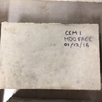
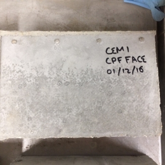
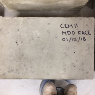
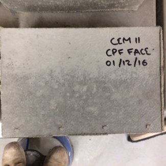
The visible blowholes of at least approximately 600 µm were circled and recorded. I chose to not record any marks under this size as it is hard to differentiate between blemishes and blowholes using regular vision under this size. The surface morphology is shown in Fig 3 with the recorded blowholes circled. The results show that the MDO lined blocks had 175% more blowholes than the CPF lined blocks for the CEM I mix and 185% more blowholes in the CEM II mix.
Fig 3 –Blowholes in different formwork facing materials
Discussion
Slump results
The CPF blocks are darker at the bottom where the majority of the blowholes occur. I believe with a higher compaction the CPF liner would allow more free water and air at its surface to escape creating an almost completely blowhole free surface. The MDO blocks are non-uniform in colour and I believe this is due to excess patches of water bleeding to the surface during compaction causing a darker colour, and accumulation of cementitious particles in the lighter areas.
Compressive strength
As mentioned in the Schwinn hammer rebound test results, the CPF did not gain compressive strength in the compression test in proportion to the rebound test. As I before stated, I believe this is due to the casting of the CPF specimens. Furthermore if they were cast to the exact same dimensions as the specimens in plastic moulds they would have provided a higher strength than them in proportion to the rebound hammer test results.
Table 4 – Results of Compression test on concrete: EN 12390-3
| Specimen ID. | Water/cement Ratio | Age | Date tested | Mass (Kg) | Density (Kg/m³) | Area (mm²) | Failure (kN) | Stress (MPa) | Failure appearance | |
| Cem I – Plastic – 1 day | 0.47 | 1 | 02/12/2016 | 2.302 | 2302 | 10000 | 201.2 | 20.12 | ok |
|
| Cem I – CPF – 1 day | 0.47 | 1 | 02/12/2016 | 2.224 | 2224 | 9370 | 129.8 | 13.85 | ok |
|
| Cem II – Plastic – 1 day | 0.46 | 1 | 02/12/2016 | 2.361 | 2361 | 10000 | 255.8 | 25.58 | ok |
|
| Cem II – CPF – 1 day | 0.46 | 1 | 02/12/2016 | 2.191 | 2191 | 9370 | 146.6 | 15.64 | ok |
|
| Cem I – Plastic – 8 days | 0.47 | 8 | 09/12/2016 | 2.302 | 2302 | 10000 | 374.5 | 37.45 | ok |
|
| Cem I – CPF – 8 days | 0.47 | 8 | 09/12/2016 | 2.224 | 2224 | 9370 | 361.7 | 38.6 | ok |
|
| Cem II – Plastic – 8 days | 0.46 | 8 | 09/12/2016 | 2.361 | 2361 | 10000 | 452.2 | 45.22 | ok |
|
| Cem II – CPF – 8 days | 0.46 | 8 | 09/12/2016 | 2.191 | 2191 | 9370 | 382.1 | 40.78 | ok |
|
| Cem I – Plastic – 28 days | 0.47 | 28 | 29/12/2016 | 2.33 | 2330 | 10000 | 465.1 | 46.5 | ok |
|
| Cem I – CPF – 28 days | 0.47 | 28 | 29/12/2016 | 2.35 | 2350 | 9370 | 360.6 | 38.48 | ok |
|
| Cem II – Plastic – 28 days | 0.46 | 28 | 29/12/2016 | 2.36 | 2360 | 10000 | 553.3 | 55.3 | ok |
|
| Cem II – CPF – 28 days | 0.46 | 28 | 29/12/2016 | 2.36 | 2360 | 9370 | 372.2 | 39.72 | ok |
|

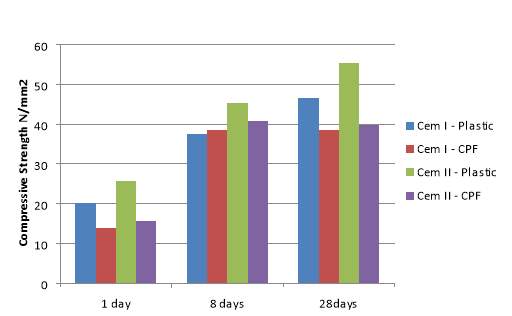
From the results given in the compression test it shows the plastic lined specimen to be on average 30% stronger than the CPF lined specimens. Fig 4 shows the strength achieved at different ages.
Fig 4 – Results of compression test on concrete: EN 12390-3
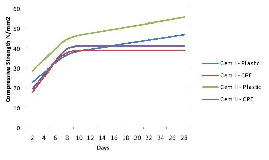
If the specimens were cast correctly I believe that the compression results would be similar at 28 days to the rebound test results. If this was the case it would show an early gain in strength of almost 90% at 7 days before it finally reached its 28 day characteristic compressive strength. I have shown a representation of what the results may have shown if this was true in Fig 5.
Fig 5 – Predicted results of compression test on concrete: EN 12390-3
I had predicted a result such as the one in Fig 5 before testing to show that the increased durability would directly affect the strength of the concrete. At this time I cannot confirm that this is true from my results, but in the event of a retest this may be true.
| Water absorption % | |||
| Cem I – MDO | 3.65 | ||
| Cem I – CPF | 3.36 | ||
| Cem II – MDO | 2.5 | ||
| Cem II – CPF | 2.26 | ||
Water absorption
The results show comparatively similar figures, but I believe if permeability test such as a sorptivity test was available to me, it would show CPF to have a far lower permeability than the MDO lined specimens.
A lower permeability concrete especially in concrete surfaces will increase durability, this low permeability is achieved by the high density surface provided by the CPF liner. The concrete permeability will affect the quantity of chloride and water ingress. The ingress of fluids and freezing and thawing will cause cracks to occur. This compromises the strength of the concrete and can leave reinforcement subject to corrosion. For this reason I believe that the increased durability of using CPF indirectly affects the strength of concrete.
Cem I shows a higher absorption in water than Cem II, this could be due to the characteristics of the PFA main addition in the Cem II mix. The PFA will use more water than ordinary portland cement leaving less free water, therefore when the specimens are cured the Cem II mix contained less air voids where free water had evaporated.
4.7 Conclusion
The Schwinn hammer rebound test shows an increase in concrete durability where the CPF liner is used. The compressive strength of the concrete increased on average 13.62% in specimens with the CPF liner.
The concrete surface of the CPF lined specimens has far less blowholes than the MDO lined, showing a more durable concrete in terms of ingress.
The compression test results did not follow my thesis, for this reason I believe the results may be a false representation of the effect of the CPF liner on strength. For this reason I have not concluded the effect that increased durability has on concrete strength.
The water absorption test showed no significant findings.
There were no significant findings on the effect of portland cement replacement materials such as pulverised fly ash (PFA) on durability of concrete.
It can be concluded that CPF liner improves the durability and strength at the surface of the concrete but there were no significant findings to show any effect on the inside.
Chapter 5: Structured interview – formwork types and design
5.0 Introduction
In this chapter I analyse the data collected from the structured interviews in Appendix 3 The Interview was presented to employees of Fox (Owmby) Ltd in the hope to find common issues that may arise whilst selecting and using formwork. I selected employees of similar experience and positions, yet all slightly different. They were generally construction management professionals with lots of on-site experience.
I first designed a questionnaire for the same purpose as shown in appendix 4 but opted to change to a structured interview as I thought it would be more appropriate. This is because a structured interview allows me to ask questions and go into detail with them, it also gives better flexibility and an understanding of the answers received.
5.1 Aim
To identify common issues that may arise in formwork selection and use. I would like to use these findings to then develop a system to address a common issue found in formwork selection.
5.2 Research sample
Before I decided to use a structured interview to collect data, it was my intention to use a postal questionnaire. I decided against this due to the nature of the questions. This is because the questions may be perceived differently by individuals and it would be hard to associate this feedback correctly with the interviewee, therefore a selected sample with a structured interview would give better results.
The sample chosen is to be my colleagues at Fox (Owmby) Ltd. The candidates were selected on their experience in formwork. All candidates have been involved in the selection of formwork and management of formwork activities.
5.3 First thought questions
My first thought questions were formulated using the statements identified in the topics category when selecting my objectives. These being:
- Effect of formwork type and design on placement and compaction.
- Effect of formwork type and design on concrete finish/aesthetics.
- Effect of formwork type and design on health and safety.
The questions were first designed for the questionnaire shown in appendix 4. After review and the decision to conduct a structured interview instead was made, they were amended accordingly.
5.4 Structured interview questions
- What modular formwork systems have you used? Can you please comment on them?
This question is asked to identify the most commonly used formwork systems in our company. The option to comment on them will give an understanding of why they are selected.
- How do modular formwork systems compare with traditional timber systems?
This question is aimed to understand the interviewees view on the advantages and disadvantages of the two systems.
- Please mark on a scale of 1 to 5 (1 being least important, 5 being most important) the qualities you look for in modular and traditional formwork systems.
| 1 | 2 | 3 | 4 | 5 | |
| Speed of erection | ☐ | ☐ | ☐ | ☐ | ☐ |
| Safety of erection | ☐ | ☐ | ☐ | ☐ | ☐ |
| Quality of concrete | ☐ | ☐ | ☐ | ☐ | ☐ |
| Quality of finish | ☐ | ☐ | ☐ | ☐ | ☐ |
| Cost | ☐ | ☐ | ☐ | ☐ | ☐ |
| Accuracy of shape | ☐ | ☐ | ☐ | ☐ | ☐ |
| Reusability | ☐ | ☐ | ☐ | ☐ | ☐ |
| Ease of maintenance | ☐ | ☐ | ☐ | ☐ | ☐ |
Can you please comment on your selections?
This question gives quantitative data on the importance of inherent qualities of formwork. The option to comment on them will give an understanding of why they may be important.
- Have you ever used permanent formwork? If so what are your comments on it?
This question is asked to identify the most commonly used permanent formwork in our company. The option to comment on them will give an understanding of why they are selected.
- What methods of concrete compaction have you used when using formwork? Can you please comment on them?
This question is asked to identify the most commonly used compaction methods in our company. The option to comment on them will give an understanding of why they are selected.
- Have you used admixtures in concrete to improve outcome of concrete due to the use of formwork? Can you please comment on them?
This question is asked to identify the most commonly used admixtures in our company. The option to comment on them will give an understanding of why they are selected.
- What system of formwork would you use for the following structural elements and why?
This question is asked to identify the most commonly used formwork systems in our company for specific structural elements. The option to comment on them will give an understanding of why they are selected.
Method of analysis
The measurement of data collected from the interviews is processed into numerical scale by the use of common themes and probability. For example if all 4 interviewees answered that modular formwork was safer than traditional the common theme would score 100%, in the case where 2 or 3 thought this the score would be 50% and 75% respectively. In question 3 the average level of importance for the four most important qualities. The four most important qualities will then be processed the same as the other questions.
5.5 Results and discussion
- What modular formwork systems have you used? Can you please comment on them?
Vertical panel systems 100% – Good for applications in simple shapes, and can be easily designed to resist high pressures.
Column systems 50% – Ideal for round columns.
- How do modular formwork systems compare with traditional timber systems?
Modular systems
Low skilled operatives 75% – Allows lower cost labour.
Quick assembly 75% – Reduced programme time.
Working platforms 50% – Increased safety.
Traditional systems
Achieve complex applications 50% – Construct shapes that modular systems are unable too.
Over engineered 50% – Increased material cost
- Please mark on a scale of 1 to 5 (1 being least important, 5 being most important) the qualities you look for in modular and traditional formwork systems. Can you please comment on your selections?
Safety of erection (Importance 4.75) – Modular systems offer a higher level of safety 100%
Speed of erection (Importance 4.5) – Modular systems offer better speed of erection 50%
Accuracy of shape (Importance 4.25) – Timber systems can achieve intricate shapes 50%
Reusability (Importance 4.25) – Higher reusability equals lower overall cost 50%
- Have you ever used permanent formwork? If so what are your comments on it?
GRP permanent formwork 50% – Bridge deck applications
HD polyethylene formwork 50% – Substructure applications
- What methods of concrete compaction have you used when using formwork? Can you please comment on them?
Internal vibration 100% – Most concreting applications
External vibration 50% – Wall and slab applications
- Have you used admixtures in concrete to improve outcome of concrete due to the use of formwork? Can you please comment on them?
Plasticisers 50% – Better compaction and lower hydrostatic pressure
- What system of formwork would you use for the following structural elements and why?
Columns – Modular formwork 100%
Retaining walls – Modular systems 100%
5.6 Conclusion
From my results I have identified 3 of the most common themes in the structured interviews, these are:
- Vertical panel systems – Good for applications in simple shapes, and can be easily designed to resist high pressures.
- Safety – Modular systems offer a higher level of safety.
- Compaction – Internal vibration used in most concrete placement.
I will use these as the basis for creating a procedure for formwork selection of either traditional or modular formwork during tendering.
Chapter 6: Formwork Selection Procedure
6.0 Introduction
In this chapter I will use the findings from chapter 5 as the basis for the construction of a formwork selection procedure. This procedure will provide guidance to help select either a traditional or modular system to ensure maximum efficiency in terms of cost, time, quality and health and safety. I plan to investigate common scenarios in formwork selection to see if a procedure for carrying out this process is feasible.
6.1 Aim
Reduce time taken and increase accuracy when considering a formwork system for a tender.
6.2 Design information and considerations
To create a procedure for the selection of formwork system I am going to use Formwork: A guide to good practise and all information referred to in the text.
As identified in chapter 5 I am going to create a procedure specifically for vertical panel applications. This will be assumed as a continuous wall for design purposes with varying thickness and three different height categories. The construction of the mentioned wall will need to be double faced formwork and will allow the use of through ties.
The information used for this design may be amended for the purposes of future use, so that it is fit for purpose for this procedure. These amendments will be justified and proven to be acceptable.
6.3 Procedure
This is a step by step guide to selecting a fit for purpose formwork system.
Please note this procedure provides a quick estimate of required formwork system and should not be used for the finished design. It is mostly beneficial for the tender stage and early procurement. A blank procedure is shown in appendix 5.
6.3.1.0 Procedure introduction
I have chosen to use a excel file to formulate and conduct the proposed procedure. The excel cells will be formulated so that the user may take given information from specifications and drawings and input them into the orange cells. There is a total of 11 factors that will affect the outcome of the procedure which are associated with the orange cells. When all orange cells are filled, the procedure will provide all the answers to the following outlined for the procedure in the yellow cells. This will ultimately give a take-off at the end, which can be used for comparison of formwork systems and procurement.
6.3.1 Concrete pressure
6.3.1.1 Concrete density is assumed to be 25kN/m3
6.3.1.2 Concrete rate of delivery:
This is dependant of method of placement and site constraints. I have created three different categories for rate of delivery:
- High placement – up to 20m3/h.
- Medium placement – up to 9m3/h
- Low placement – up to 5m3/h
- Plan area of pour – This is the thickness of the wall multiplied by length.
- Rate of rise – This is rate of delivery divided by plan area of pour.
- Maximum concrete pressure.
CIRIA R108 provides a design method for formwork pressure with consideration to; the concrete, formwork and placement of concrete. Using these considerations the maximum pressure (kN/m2) exerted is formulated into a table (Table 2 – Design formwork pressures). This table provides many different situations for concrete group, concrete temperature, form height and rate of rise. Using this table I have simplified it for the use of this procedure.
Instead of using concrete groups I have decided to use cement classification in a similar way, the use of high cement replacement and the use of a retarder gives the higher figures of formwork pressure. I have changed the temperature for use in either the summer or winter.
The maximum form height that I have accounted for is 4m and the intervals of rate of rise have been reduced.
Fig 6 – Formwork pressure
| WALLS (kN/m2) | ||||||||
| CEMENT CLASSIFICATION | Conc. Temp. (oC) | Form Height (m) | Rate of Rise (m/h) | |||||
| 1.0 | 2.0 | 3.0 | 5.0 | 10 | ||||
| (A)
CEM I, II, III excluding the use of a retarder |
5
(Winter) |
2 | 45 | 50 | 50 | 50 | 50 | |
| 3 | 55 | 65 | 70 | 75 | 75 | |||
| 4 | 65 | 70 | 75 | 85 | 100 | |||
| 10
(Summer) |
2 | 40 | 45 | 50 | 50 | 50 | ||
| 3 | 45 | 55 | 60 | 70 | 75 | |||
| 4 | 50 | 60 | 65 | 75 | 90 | |||
| (B)
CEM I, II, III including the use of a retarder CEM IV, V |
5
(Winter) |
2 | 50 | 50 | 50 | 50 | 50 | |
| 3 | 70 | 75 | 75 | 75 | 75 | |||
| 4 | 80 | 90 | 95 | 100 | 100 | |||
| 10
(Summer) |
2 | 45 | 50 | 50 | 50 | 50 | ||
| 3 | 55 | 65 | 70 | 75 | 75 | |||
| 4 | 60 | 70 | 75 | 85 | 100 | |||
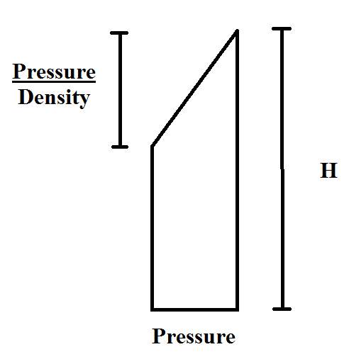
- Equivalent fluid head – In the concrete pressure diagram, the equivalent fluid head is given from the maximum concrete pressure divided by the concrete density.
Fig 7 – Concrete pressure diagram
6.3.2 Plywood
6.3.2.1 Plywood
The selection of structural plywood in the UK will usually be a Canadian Douglas Fir, 7ply 19mm kept in stock with most builders’ merchants. For this reason we will use this as a standard in its strongest direction which is with its grain parallel to the horizontal waling’s. With standard 8’ x 4’ sheets this gives a height of 2440mm.
6.3.2.2 Waling spacing
A suitable bearing width must be selected which is adequate to resist the maximum concrete pressure. It is practical to try and achieve a spacing that is economic as well as structurally suitable. A common spacing is usually 300mm centre to centre, but the effective span will vary depending on the width of the waling’s used. An example spacing for an economical product is 2440mm / 6 waling’s = 407mm centre to centre.
Fig 8 – Appendix B Loading case 58
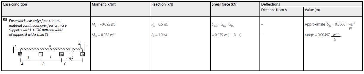
Using load case 58 I will find the adequate spacing for a range of formwork pressures:
Up to 30kN/m2 – 407mm centre to centre
31 to 55kN/m2 – 305mm centre to centre
56 to 90kN/m2 – 244mm centre to centre
This spacing is necessary for the max concrete pressure and can in practise be reduced where the pressure diagram reduces as you come up the formwork.
6.3.3 Waling’s
6.3.3.1 Permissible stresses
Waling’s are most commonly of strength class C16, and either a section of 50 x100, 50 x 150 or 75 x 150 depending on the formwork pressure. Using these two sections I will identify what pressure each section’s permissible stresses can satisfy depending on the three waling spacing’s identified in 6.3.2.2.
Fig 9 – Permissible stresses in solid timber for wall formwork
| C16
50 x 100 |
C16
50 x 150 |
C16
75 x 150 |
|
| Allowable bending stiffness, kNm2 | 25.16 | 84.06 | 128.77 |
| Allowable moment of resistance, kNm | 0.582 | 1.244 | 1.906 |
| Allowable shear load, kN | 4.53 | 6.77 | 10.37 |
| Allowable bearing stress, kN/m2 | 2300 | 2300 | 2300 |
6.3.3.2 Maximum distributed load on each waling
This will be the maximum concrete pressure times the waling spacing.
6.3.3.3 Soldier spacing
We will assume soldiers are placed at every 1200mm (4’) as good common practise.
6.3.3.4 Bending moment check
Max bending moment
The maximum bending moment found using the worst case condition from load case 37 of Formwork: A guide to good practise.
Max bending moment: -0.0911 wL2
6.3.3.5 Shear check
Max shear
The maximum shear is found using the worst case condition from load case 37 of Formwork: A guide to good practise.
Shear: 0.535 wL
6.3.4 Soldiers and ties
6.3.4.1 Reactions at soldiers
The maximum reaction is found using the worst case condition from load case 37 of Formwork: A guide to good practise.
Max reaction: 1.048 wL
6.3.4.2 Soldiers
In walls of over 1.2m in height it is best practise to use a proprietary soldier.
To select an adequate soldier we need to first find the maximum equivalent distributed load. This is found by dividing the maximum reaction by the waling spacing.
For the total load in the soldier we will assume a pressure diagram for a simplified calculation that will provide a less favourable load.
Fig 10 – Soldier loading diagram
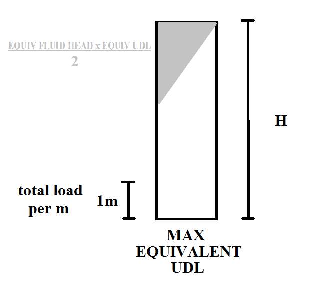
By multiplying the max equivalent UDL by H and then subtracting half of the equivalent fluid head times by the max equivalent UDL we will get the total load in the soldier.
6.3.4.3 Ties
To select an adequate tie and waling plates we will need to know the maximum tie load. Usually using moment distribution we would find the exact load through the ties but for the purposes of this procedure and the use of its simple load conditions we will add 5% to the load found in the loading diagram. Therefore the maximum tie load will be total load in the soldier multiplied by the maximum tie spacing times 1.05.
6.3.5 Stability
For the stability of a double faced wall we only consider each face individually, and both faces will be equal.
6.3.5.1 Wind factor, Swind
Swind =Twind x vb, map x (1+Altitude/1000)
Fig 11 – Topographical factor, Twind
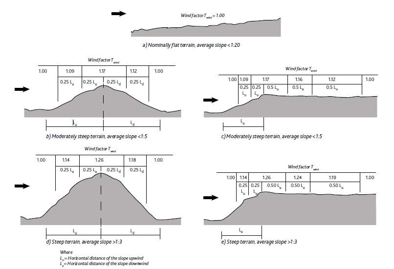
Twind, Ave: 1.00
Twind, Ave: 1.08
Twind, Ave: 1.13
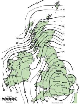
Fig 12 – Wind velocity, vb, map
6.3.5.2 Overturning moment
To find the overturning moment we have to first find the combined exposure factor and multiply it by the squared wind factor.
The combined exposure factor is found using its height and the distance to shoreline.
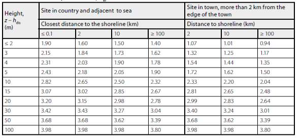 Fig 13 – Combined exposure factor, Cef
Z = height of formwork
hdis = distance to shoreline
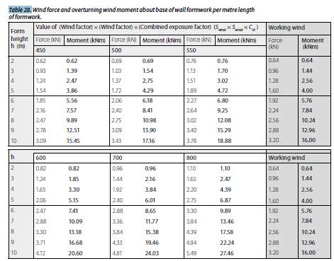
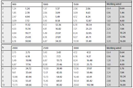
Then by interpolation of the table in Fig 14 you can find the maximum wind overturning moment and the working wind overturning moment.
Fig 14 – Overturning moment about base of formwork per metre
6.3.5.3 Minimum stability force
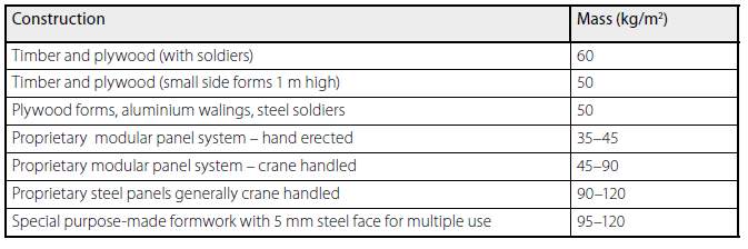
The minimum stability force for wall formwork is 10% of the formwork self-weight. This includes both sides of the double faced wall formwork.
Fig 15 – Typical formwork self-weight
6.3.5.4 Working platform loading
Assuming a 0.8m wide working platform the working platform is a cantilever and we will assume a lever arm of 1.0m for the purposes of this procedure. A minimum working load on the platform is 0.75kN/m2. Therefore the nominal working overturning moment will be 0.8 multiplied by 0.75 multiplied by the length of the working platform.
During construction working load will increase to 1.5kN/m2. Therefore the full construction overturning moment will be 0.8 multiplied by 1.5 multiplied by the length of the working platform.
6.3.5.5 Stability checks
1. Maximum wind plus nominal access load on platform
2. Working wind plus full construction load on platform
3. Minimum stability plus full construction load on platform
Using the maximum overturning moment from the above checks we will add a factor of safety of 1.2; this value will be the value that the supports must resist.
6.3.5.6 Push/Pull support
A good angle for a push/pull prop is 60o, and a good position for the prop on the wall formwork is H x 3/5. Using Pythagoras theorem we can find the unknown dimensions and the load through the prop.
6.3.5.7 Anchorages
The load through the prop will then be transferred through the anchorage. Therefore we must find the horizontal and vertical load in the anchors.
6.3.6 Take off
6.3.6.1 Take off
Using all of the information found in the procedure it formulates a simple take off; this can then be used for the purposes of estimating.
Examples for procedure
Three examples of a double faced formwork wall were applied to the procedure. These results are shown in appendix 6.
The following information must be provided to successfully complete the procedure:
- Wall dimensions
- Concrete classification and density
- Rate of concrete placement
- Location and elevation
- Time of year
Example 1 – For the first example I have used the worked example from formwork a guide to good practise worked example one – double faced wall formwork.
Example 2 – For the second example I have used a wall with a small length which will increase the rate of rise which will affect the pressure placed on the formwork.
Example 3 – For the third example I used a longer length wall which reduced the rate of rise, but also increased the rate of placement which would increase the rate of rise.
Conclusion
From the construction of the procedure I feel that it will be beneficial, in the case of providing a take-off for a traditional formwork system. It would then be appropriate to compare this against the hire of a modular system before an estimated cost for the formwork is decided, and included in a tender document.
I would advise a regular review of the procedure to check that the cost indicated is accurate and reflects the cost that is recorded in the contract costs if the work is won and undertaken. Also it would be beneficial to continuously improve the precision of the procedure document by adding more information highlighted as important.
Areas I feel would already benefit from review are the variance of materials and sections, to give a more realistic and wider range of results. To improve precision I feel that the formwork pressure result could use further interpolation between its varying factors. Also the spacing of elements could be more flexible, as in design the given sizes may not necessarily be the most practicable.
Chapter 7: Conclusions
This dissertation researched the advantages of innovation in formwork types and design, and how alternative practises can be used to benefit the user.
As the world is at this innovative period the construction industry is at the forefront and is utilising innovation to improve productivity.
The manufacturing of fit for purpose formwork materials is important to achieve a concrete product in the most proficient way. The use of cement replacements is also an affordable way to achieve the correct concrete as well as having massive sustainability advantages.
The use of CPF liner produces a concrete with a higher density surface. The main advantages of this are that it is more appropriate in marine environments due to its low permeability. Due to the formwork creating this denser surface, the concrete is able to neglect the use of admixtures to achieve this effect which may be harmful to the marine environment and also in applications where potable water is involved.
When investigating common themes that may arise whilst selecting and using formwork systems. I paid special attention to how I could use my practical experience to use to benefit my employer. The structured interview identified that concrete wall applications for formwork were common and that the selection of its formwork system was important due to high formwork costs and safety issues.
To practise an innovative technique myself I created a procedure for quickly identifying the materials needed to undertake a concrete wall application my employer will be able to identify the most feasible formwork system. This will need to also consider the price of materials in comparison with the hire of a modular system. Then the consideration of other important factors such as safety and speed will also affect the final decision.
Cite This Work
To export a reference to this article please select a referencing stye below:
Related Services
View all


Related Content
All TagsContent relating to: "Design"
Design is utilised in a broad range of industries and could include any number of different subjects from architecture and interior design, to products, packaging, logos, vehicles or anything in between.
Related Articles

DMCA / Removal Request
If you are the original writer of this dissertation and no longer wish to have your work published on the UKDiss.com website then please: