Boat Hull Dynamic Lift using Water Surface Impact
Info: 9586 words (38 pages) Dissertation
Published: 9th Dec 2019
Tagged: EngineeringMaritime
Abstract
This project aims to test an alternative system to generate lift. It makes use of the water surface impact to ‘hit’ the water and produce sufficient force to overcome the weight of the hull. The system was first scaled from a basilisk lizard and a theory was developed to estimate the magnitude of force generated by the system. Whilst the experimental process failed to continue, a CFD (computational fluid dynamic) analysis was done to generate result to justify the magnitude of force generated by the paddlewheel. And
Nomenclature
ABS – Acrylonitrile butadiene styrene
ACV – Air Cushioned Vehicle
CFD – Computational Fluid Dynamic
RPS – Rotation/revolution per second
ITTC – International Towing Tank Conference
FRP – Fiber Reinforced Plastic
VOF – Volume of Fluid
CD – Coefficient of Drag
ρ – Density of a given fluid
∇ – Underwater volume
τ – Torque
F – Force
5.2 Finite Element Analysis (FEA)
5.4 Computational Fluid Dynamics (CFD)
7.2 Performance against other high-speed crafts
1. Introduction
Hydrofoil has been a popular way to lift a hull from the water to reduce hull drag hence improve the overall power and speed of the craft. However, in nature there are numerous ways for an animal to make use of a different ways to ‘run’ across water. The basilisk lizard is often recognized for their ability to run across water to evade predators, the size of their feet is relatively large comparable to their bodies, this has aided them to generate sufficient upward impulse to support their body weight. The movement of their tails provided some form of stability support preventing them to fall sideway whiles running (S. Tonia Hsieh and George V. Lauder, 2004). Many water birds have also been seen to use their wings for support and ran across water. The primary aim of this project is to investigate if a propulsion system could make use of basilisk lizard’s movement, and to prove that surface water impact would be sufficient to lift a hull from the water surface.
A simple paddle-wheel system was then decided to be used to mimic the behavior of the basilisk lizard movement and tested against common high-speed craft models for any advantage over them.
The idea of paddle propulsion has been around since ancient time, both Egyptians and Romans were aware of it. However, the first recorded use of this type of propulsion was in 1472 in ‘De Re Militari’ by R. Valturius. The use of paddle propulsion did not come in popular until a few decades later, it was the main form of propulsion for some time until screw propeller started to appear. However, It was not soon until paddle wheel become extinct from sea-going vessel, not because of their overall efficiency but due to its large change in draught and ease of being damaged (H. Volpich, I.C Bridge, 1955). Nowadays, paddlewheel vessel has become a specialized craft, primarily based on slow speed vessels in river. Although there are significant disadvantages on using the paddle wheel, the efficiency of the paddle wheel in shallow water application is significantly higher than waterjet or screw propulsion.
Chapter 2 would first look at some previous example of works done relating to paddlewheel and lizard, these papers would then be review for their usefulness to this project. A scaled preliminary design would be done in chapter 3 which made use of the size of the lizard then scaled accordingly to a model size for calculation. Chapter 4 would then develop a basis theory of force generated by the paddlewheel, the initial idea was taken from Alexander’s work in 1983. (Alexander K. V., 1983) Methodology would then be summarized in chapter 5 discussing design iteration and FEA to validate the strength of the structure. Motor power would also be estimate and the process of setting up CFD analysis would also be introduced. Chapter 6 would describe how experimental method would take place and variables that would affect the result. Chapter 7 would then look at the result of the CFD on the magnitude of lift force generated in it. Finally, the conclusion would be drawn in chapter 8.
2. Literature review
These literatures have provided supports and backgrounds knowledge for this project. Paddlewheel propulsion was only thought as a propulsive device only, limited paper addressed the lift force that paddlewheel generated, Alexander and Wray & Starret were the exception. They both addressed paddlewheel that ran in high RPS to provide. Although Alexander were the only one who investigate the lift force generated. One paper suggested a using a robot to mimic the basilisk lizard with four footpads which turned out to be unsuccessful.
Paddle wheels, Pt I: Preliminary model experiments. Paper no. 1193, Transations of the Institution of Shipbuilders and Engineers of Scotland
Volpich and Bridge, 1955-1957
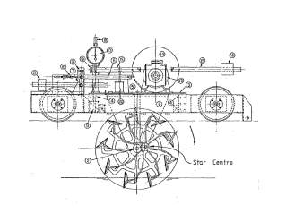 These authors explored variables in a paddle wheel system which provided some measurement on efficiency and design of a paddle wheel. It was one of the first paper to test paddle wheel system in a tank test, providing some basis on any kind of further research. It also provided some preliminary setup to test the wheel, as it is different from a modern-day tank test. The paddle wheel must be able to spin whilst attached to a support as the hull will not be available by then. A figure of their set up was included in Figure 1. Their experiment setup was to measure thrust force as lift force was not in their interest as a form of propulsion back then.
Figure 1. The experiment set-up by Volpich and Bridge 1955
They tested on both fixed angle wheel and feathering wheel which the paddle angle changed during the rotation for an optimal angle of entry of paddle with the water surface. Their experiments have proven that feathering wheel will increase the efficiency of thrust produced, therefore any further tests were focused on feathering wheel. The star center of the feathering wheel is the center of the extra iron frame in a paddlewheel which can pivot the paddle slightly to optimize the angle of entry.
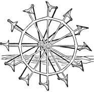 Although the feathering wheel has been proven to have higher efficiency with a given power, the idea of employing a feathering wheel in this project was quickly given up as it would have complicated the wheel with an extra variable, however, it could be done as a further research into this subject in the future. Figure 2. shown an example of a feathering wheel.
Figure 2. An example of a feathering wheel
Running on water: Three-dimensional force generation by basilisk lizards
S. Tonia Hsieh and George V. Lauder 2004
In order to understand clearly on how the basilisk lizard moves, these authors conducted a series of test to generate data on the patterns of water flow induced by the lizard foot and tracked different location on the lizard to be tracked to develop a relationship between body parts of lizard. The size of the vortex ring was also measured by the system, the paddle chord and span were then decided using vortex ring generated by the lizard as the size of the lizard feet was not available anywhere.
Dynamic Modeling of a Basilisk Lizard Inspired Quadruped Robot Running on Water
Hyun Soo Park, Steven Floyd, and Metin Sitti
This paper modelled the motion of basilisk lizard using a quadruped robot. Their analysis mainly focused on stability issues as the center of gravity of the robot was situated far away from the water surface therefore creating a problem on the stability of roll motion. The main intake from this article was the dimension of the robot and a different kind of paddle used in their experiments. A circular foot with compliant flaps were deployed as an alternative footpad design. When the robot foot is pulling out of the water, the two flaps on the front and back of the foot collapse downward to reduce the area of the footpad normal footpad which could be useful to the project.
The robot did not manage to run across the water, as per the authors state the stability of the robot was an issue as there was a large roll moment and the force generated by the footpad was not great enough to overcome the weight of the body. The idea of producing a quadruped robot was quickly abandoned for this project, reasons are as follow:
- Stability issue would be a problem as the robot would have to be balance using four singular points on the water surface, whilst the stability of a hull with paddlewheels would mainly be stabilize by the hull itself, introducing no extra variables to influence stability.
- The cost of building robot would be significantly higher than a paddlewheel with near to no electronical part, except for the motor which drives the wheel.
- This type of robot is impractical to build and employ in real world situation. Their work was mainly focused on proving lift force can be generated by viscous drag force.
- As the author mentioned the robot did not manage to generate enough lift to overcome weight, the weight of the robot would be harder to decrease because of the essential component to drive it. However, the weight of a hull would be far easier to reduce as there won’t be as many components as the robot.
A Model Study of the Hydrodynamic Characteristics of a series of Paddle-Wheel Propulsive Devices for High-Speed Craft
Wray, G. A. & Starrett, J. A. (1970)
Wray and Starrett were the first few to investigate use of paddle wheel on a high-speed craft. Traditionally, paddle wheels are big and slow which are fitted in a steamer, however these authors had an idea to use a paddle wheel of small diameter with high rotational speed, to be employed on a planning hull patrol boat. Few points from their conclusions were proved to be important on the design of the paddle wheel.
- The six-bladed wheel generates more thrust than the twelve-bladed wheel, it is also significantly more efficient than the twelve-blade wheel.
- Thrust and efficiency increase with increasing immersion depth.
- There was a break in the thrust curves at around 40% slip, that they have yet found a satisfactory explanation.
The use of high speed paddle wheel could be related to the this. The break in the thrust curves was to be identified as cavity intrusion (Alexander K. V., 1983), this will happen if a blade hit the air pocket generated by the previous blade, which will decrease the overall efficiency of the system and any increase in RPS will not benefit the craft speed.
The Lifting Paddlewheel: A non-buoyant wheel enabling a high speed wheeled amphibious craft to run on the water surface
K. V. Alexander (1983)
Alexander was the first and only person to propose the use of paddlewheel to lift a craft out of the water, theory was developed to describe the forces for simple flat-bladed paddle wheel. A total of 25 different type of wheels were tested in his thesis. His work was very relevant to this project as the result provided some basis information on dimensions and design of the paddle wheel. The main findings were listed below:
- Alexander has produced an optimal 12 blades paddlewheel design with a wheel diameter of 152mm. Figure 3. shown his design in detail.
- Lift force produced from the wheel was mostly dependent on the immersion and advance speed. As the immersion depth increases, the forces produced by the paddle would increase until it reaches the center line of the wheel.
- In general, increases in wheel span and chord would increase the force produced by the wheel as more mass of water were actuates for each revolution.
- The lifting paddlewheel craft has wake regime of a boat hull consist of displacement, semi-displacement and planing.
Alexander’s results have reduced the number of variables this project has to investigate, and verified data that was scale from lizard to be similar with the results he produced.
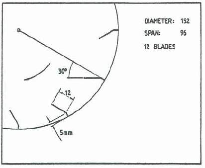
Figure 3. The most promising wheel from Alexander’s thesis.
CFD Analysis of a High-Speed Paddlewheel
W.C. Bowen and K. V. Alexander (2010)
These authors conducted some CFD study on the preliminary work of Alexander back in 1983, their simulations were conducted in Ansys CFX v12.1. It involved of modelling transient analysis, which include solving VOF equation for two fluid (water and air) dispersing throughout a flow domain. Both 2D and 3D models were analyzed. The results were then compared against the work Alexander did in the previous thesis.
These results could be used to measure the accuracy of the experimental results produced by the current project. The 2D results did not reached a steady state force or repeating pattern, therefore Alexander selected a time interval and average out the force per unit spin, an example of the time interval selected was shown in Figure 4.
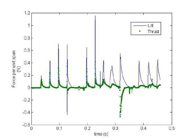
Figure 4 CFD Propulsive force for 5RPS wheel
The method of CFD could be apply to this project and helps to set the simulation up with small amount of time. They also did a test on how number of elements would affect the simulation outcome by modelling a flat blade dropping vertical downward to the water surface and observing the water splash generated by each case.
Summary
The idea of employing high speed paddlewheel was not tested as screw propellers often offered a more beneficial operating condition such as, paddlewheels were more likely to be damage and the overall operating equipment took up a lot of space on a vessel. However, it has an relatively high efficiency and it seemed like the limit of paddlewheel has yet to be achieved. Alexander had shown a reasonable progress on his idea of lifting paddlewheel, and Wray demonstrated that a six-bladed wheel was more efficient than a twelve-bladed wheel. It could be useful to produce a series of standard data for paddlewheel design which would improve the paddlewheel and explore alternative usage of it, for example as a small automatous craft working in shallow water.
3. Preliminary design
Information of the basilisk lizard were first collected and scaled to a craft size data. It was logical to keep the craft weight and size small to replicate it as a lizard model. In Table 1, it shown a scale factor of 5 from the lizard itself to the craft. This scale factor was chosen because it gave a reasonable size of a model craft size and it was convenient paddle size to compare against result from Alexander’s work. The weight of the craft could however be lighter to reduce the force required to generate.
As all lizards varied in weight, size and speed, an average value was taken to scale it from lizard size to craft size. The feet size of the lizard has proven hard to be found; therefore, the span and chord of the paddle wheel were estimated from the vortex ring size generated by the lizard feet of 0.03m2(S. Tonia Hsieh and George V. Lauder, 2004).
| Scale Factor | 5 | |
| Lizard | Craft | |
| Speed (m/s) | 1.45 | 3.24 |
| Weight (kg) | 0.20 | n.a |
| Force required (N) | 0.98 | n.a |
| Length(mm) | 430 | 2150 |
| Length without tail(mm) | 116.10 | 580.5 |
| Step period (s) | 0.10 | n.a. |
| Frequency (Hz) | 5 | 5 |
| Vortex Area (mm^2) | 706.86 | 17671 |
| Span (mm) | n.a. | 96 |
| Chord (mm) | n.a. | 18 |
Table 1. Scaling calculation from lizard to craft size.
As the craft’s length and speed was determined, it was then logical to find suitable hull parameters for the craft. Table 2shown ratios such as L/B and B/T, to calculate the craft basic dimension. These ratios were taken assuming the hull type was a high-speed planing hull, these ratios would differ from cargo ship but closer to passenger ship. (Professors R A Shenoi and R V Pomeroy, Mrs. G A Keane and Dr. D J Taunton, 2017)
| L(m) | 0.581 |
| B(m) | 0.073 |
| T(m) | 0.015 |
| D(m) | 0.048 |
| L/B | 8 |
| B/T | 5 |
| B/D | 1.5 |
| Fn | 1.358681 |
| ∇ (m^3) | 0.611303 |
Table 2. Derived Dimension of the proposed model craft
The buoyancy of the craft in an equilibrium case could therefore be derived by simply multiplying the water density and gravity into it. In fresh water, ρ = 1000kgm-3, therefore the derived buoyancy would be 6kN. However, this buoyancy would only be required where the craft is stationary. When the paddlewheel is operating, it would generate lift force and it would match ∇ therefore the craft should start rising from the surface and ‘walks’ on the water surface. And when the transfer of momentum becomes larger, this force would take over the buoyancy where it becomes negligible as the hull of the craft would be out of the water. The hull drag would then reduce to aerodynamic drag rather than hydrodynamic drag. To demonstrate the difference of the hull in water and in air, the drag equation was employed and displayed below in equation 1.
To help visualize this, Figure 6 was plotted below.
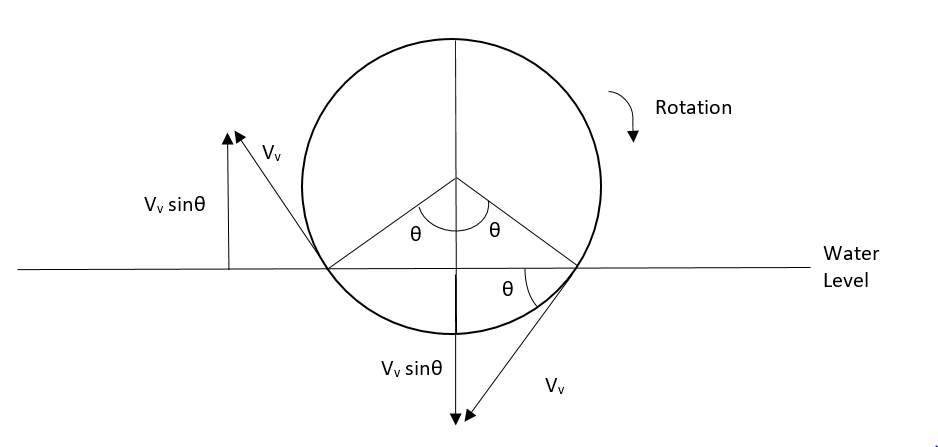
Figure 6. Visualization of vertical force acting on the water
The angle θ depended on the immersed depth, the deeper the wheel was immersed, the larger θ would be. A simple trigonometry equation can be made below to calculate the angle θ.
sinθ= r-immersed depthr
( 10 )
Table 4 was made to estimate the lift force generated by the blade. Immersed area and radius would follow what it was in the estimation for thrust.
Table 4. Lift Force estimation with varied RPS and Immersion Depth
| RPS | Lift Force (N) | |||||
| 5 | 2.728 | 3.312 | 3.604 | 3.750 | 3.824 | |
| 6 | 3.273 | 3.975 | 4.325 | 4.501 | 4.588 | |
| 7 | 3.819 | 4.637 | 5.046 | 5.251 | 5.353 | |
| 8 | 4.364 | 5.299 | 5.767 | 6.001 | 6.118 | |
| 9 | 4.910 | 5.962 | 6.488 | 6.751 | 6.882 | |
| 10 | 5.455 | 6.624 | 7.209 | 7.501 | 7.647 | |
| 1.425 | 2.85 | 5.7 | 11.4 | 22.8 | Immersion depth (mm) | |
4.3 Summary
Lift force and thrust force estimation were done in this chapter. The thrust force magnitude mainly depends on immersed area and RPS value, while the lift force would also depend on immersion depth on top of those included in thrust force. Higher immersion depth would provide a larger lift force in Table 4. However, the estimation done in Table 4 did not account for the downward Vvwhich would drag the wheel downward instead of the upward force it needed. Summarizing through Table 3 and Table 4, it seems logical that a higher RPS would increase the magnitude of force generated, however, these values also excluded the effect of cavity intrusion which was discussed in Alexander’s and Wray & Starrett work. A wheel can only have a limited maximum RPS, in higher RPS the blade would hit the air bubble generated by a previous blade, which decrease efficiency. This would be dealt with more in chapter 6.
5. Methodology
5.1 Wheel Design Iterations
There were three different paddle wheels made to test the optimal setup of it, as different angles, blade shape, and number of blade would impact the size of both thrust and lift force of the wheel. The surface area of the paddlewheel was to keep as a near constant for the ease to compare their performance against each other. The first design of the wheel was taken from Alexander’s thesis proposed with the dimension listed shown in Fig.5 (Alexander K. V., 1983) which was similar in size from the scaling of lizard to craft size listed in Table.1. Another two wheels were designed with different angle or shape of blade to verify if that design was the optimal and were included in the Appendix.
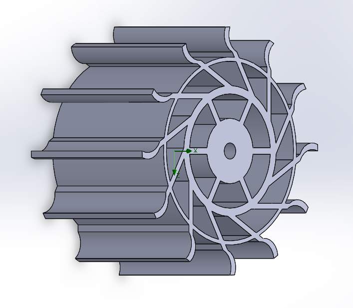
The paddlewheel was first designed in Solidworks such that it can be 3D printed for accuracy and quality (Solidwork 2016). The 3D printed model should have the strength to withstand bending stress cause by the rotation of blade across the water surface. As ABS polymer lack the strength to resist stress cracking, structures were added in to strengthen it. Figure 7 shown the wheel in Solidworks and Figure 9. shown the same wheel with the top removed for the ease of observation. The span of each paddle was supported by 7 points which were connected to the side wall and to the center wheel which would be connect to the shaft from the motor. The design was overbuilt such that any stress cracking can be avoided during the testing phase in the towing tank. The weight of the wheel also needed to be kept to a minimum as the rotation of the wheel cause a dynamic problem, keeping the weight down would increase the natural frequency of the system to reduce resonance during testing. As the natural frequency depends on the stiffness, k, and the mass, m following the equation below. As the equation suggested, the stiffer the object and the lighter the mass is, the higher the natural frequency would be.
ω2=km
( 11 )
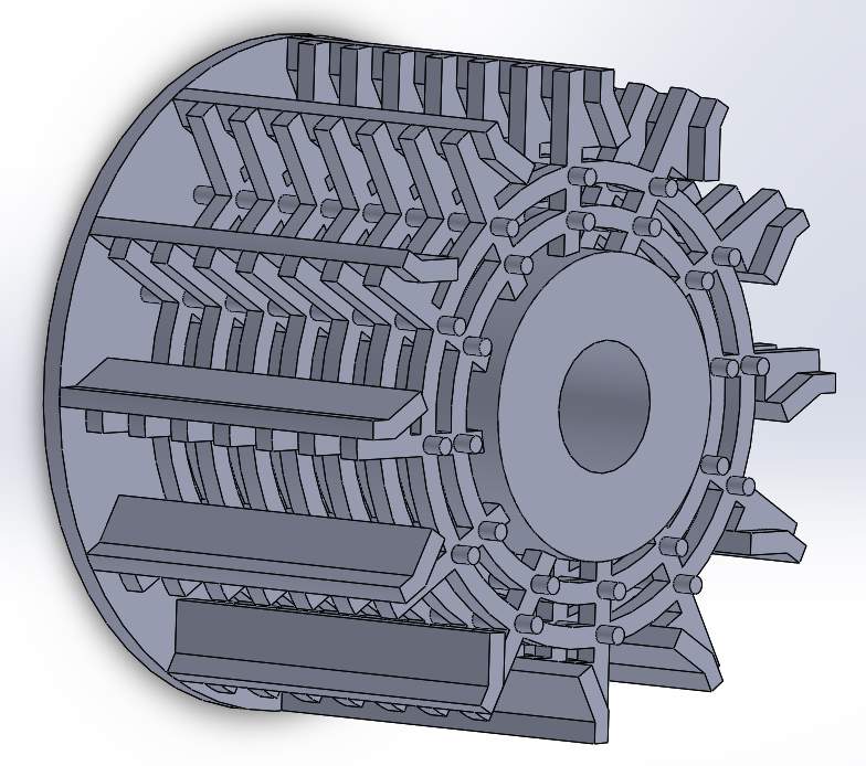
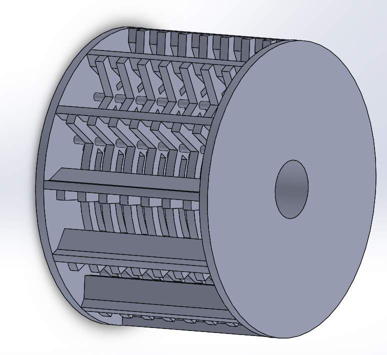
Figure 7. Designed wheel for ABS 3D print Figure 8 Designed wheel for ABS 3D printed with the top removed
This design was then disregarded due to the unavailability of the ABS machine installed in the University. A simplified version of the original wheel was made as metal print was offered as an option to manufacture the wheel, these structures would no longer be useful as the strength of (what type of metal) are higher than that for ABS polymer. Figure 9 shown the simplified wheel designed in Solidworks to be metal printed. Majority of the supports were removed to reduce weight and cost of the production.
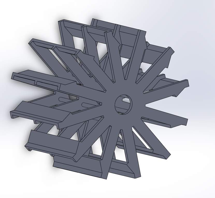
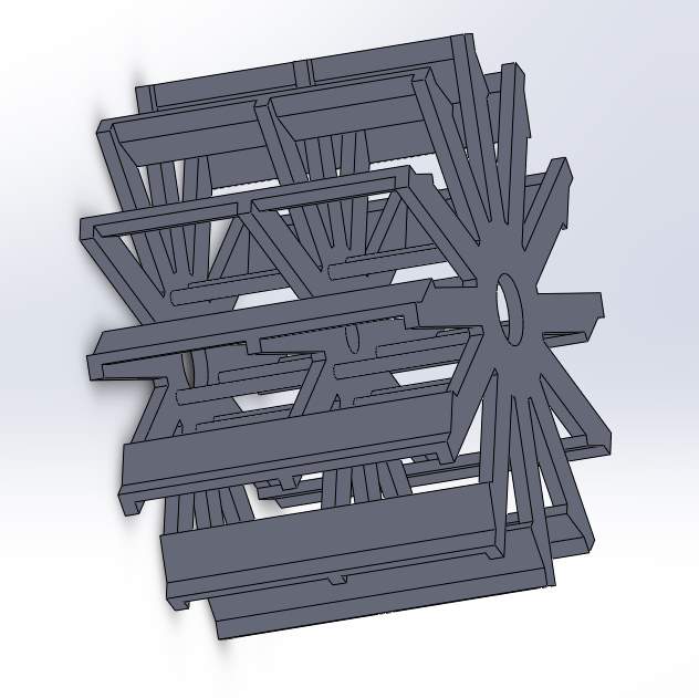
Figure 9 Simplified wheel removing supporting structures to minimize weight.
The wheel was to be finalized here, however once entering the production stage of the wheel, it was realized that supporting structure were needed as 3D printed parts are built layer by layer, a previous layer was required for any structure to be built upon (Cain, 2018). Figure 10 shown the layer needed for the penultimate design. The supporting structure would then have to be removed, the removing process would likely to damage the model leading to an imperfection which contradict the choice of using 3D printing. Therefore, another new model was made for the ease of production and post processing which is shown in Figure 11. The new model would be easier to print and the size were identical to the previous wheel shown in Figure 9with one significant different, the outer wall was added in to support the paddle as a finite element analysis shown the region was prone to a high stress, this would be discussed more in depth in the next chapter.
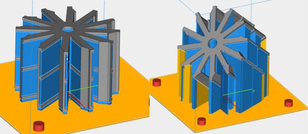
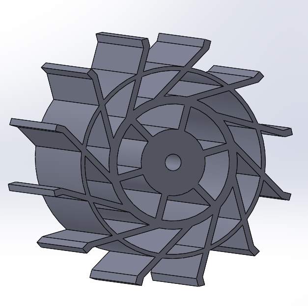 Figure 10. The supporting structure needed for the model to be 3D printed
Figure 11. The final design of the paddlewheel
5.2 Finite Element Analysis (FEA)
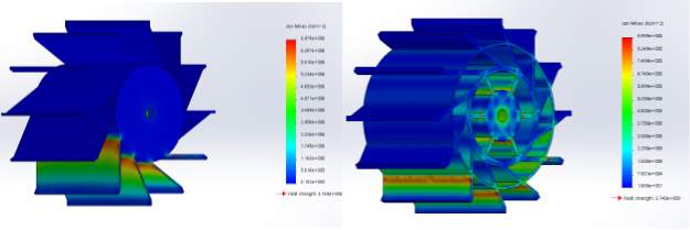 Finite element analysis is a numerical method to solve engineering problems, the object was to be mesh into smaller parts and equations were used to model these small parts and assembled back into the system to model the problem. (Harish, 2018) Series of FEA were done to ensure the strength of these models were sufficient to withstand the torque and to locate any excessive deflection, these tests were all done in Solidworks Simulation. These included: static test for stress, strain and displacement. Although these tests would not be perfectly accurate because of the constantly changing force opposing the motion in the fluid, it would be enough to show the structures would not crack under the load condition. These tests would show any stress over the tensile strength of the material and marked them with a darker color. A comparison between a wheel with support and without was also tested to demonstrate the difference of stress of the models. This is shown in Figure 12.
Figure 12. Stress test for wheel with outer ring support and without.
In Figure 12, each of the immersed blade were subjected to a constant normal force of 12N which should be high enough to simulate the blade in action as suggested in table 3 and 4. 12N was chosen based on the resultant of both force by square root of the sum of the squared lift force and thrust force. In reality, the force would be distributed through the structure as most of the momentum exchange would happened instantaneously when the blade hit the water surface, and no single blade should have to handle the 12N all together.
Two materials were available in the 3D printer, aluminum and stainless steel. Whilst aluminum is a light weight metal which benefit the experiment, stainless steel has higher overall strength, therefore stainless steel was chosen instead of aluminum because of the torque and force the wheel would experience during the testing phase. Their properties were listed in Table 5for ease of comparison.
Table 5. Properties of Stainless Steel 316L and Aluminum
| Stainless Steel | Aluminum | |
| Yield Strength, N/mm2 | 374 ± 5 | 211 ± 4 |
| Tensile Strength, N/mm2 | 650 ± 5 | 329 ± 4 |
| Elongation, % | 65 ± 4 | 9 ± 1 |
| Young’s Modulus, N/mm2 | 200 x 103 |
|
5.3 Motor Power Estimation
Motor size was determined by the needed rpm for paddle wheel which is between 5-10rpm. Motors that are oversized and underloaded will overhead and lose efficiency, therefore a suitable size must be determined.
To determine the size of the motor, the torque must be calculated. Using the following relationship:
τ=F r
( 12 )
where r =radius, F = force
The force produced by the blade was unknown to start with, therefore this was assumed by taking the result from Alexander’s tank test. (Alexander K. V., 1983) And the corresponding torque was calculated and therefore the required power could be determined by multiplying the angular velocity (rad/s) with torque. Table 6 listed the power required for different RPS and force setting.
Table 6. Required power with different RPS and force
| Force (N) | Motor Power(w) | ||||||
| 12 | 28.65 | 25.79 | 22.92 | 20.06 | 17.19 | 14.33 | |
| 11 | 26.26 | 23.64 | 21.01 | 18.38 | 15.76 | 13.13 | |
| 10 | 23.88 | 21.49 | 19.10 | 16.71 | 14.33 | 11.94 | |
| 9 | 21.49 | 19.34 | 17.19 | 15.04 | 12.89 | 10.74 | |
| 8 | 19.10 | 17.19 | 15.28 | 13.37 | 11.46 | 9.55 | |
| 10 | 9 | 8 | 7 | 6 | 5 | RPS | |
5.4 Computational Fluid Dynamics (CFD)
The reason to use CFD to verify the accuracy of the experimental result, and to simplify the process of testing different paddlewheel without the need to manufacture them. The Solidworks package contain a simple flow simulation, however, after the first trial it was realize that the flow simulation in Solidworks would not simulate an accurate model due to two main reasons. (Matsson, 2010)
- Free surface phenomena: The software could not handle the complexity and non-linear of the top layer of liquid sitting on an open tank
- Moving bodies: Any moving bodies would displace a certain mass of fluid with it, Solidworks Flow Simulation does not contain any coding to handle Fluid structure interaction.
Considering the problem this project that needs to investigate, firstly the paddlewheel contains paddle blades that would displace water therefore a moving body. Secondly, the paddlewheel would sit on top of the surface of the water, moving cross two fluids, air and water, the free surface would be interfered by the blades and hence the free surface phenomena.
To summarize, Solidworks Flow Simulation would only simulate a stationary paddlewheel immersed in water, which could simulate drag and lift force for a couple blades under water. An alternative software, such as Ansys, would have to be used for model a moving paddlewheel hitting the water surface and lift force for future work.
Ansys CFX (Ansys, 2017) was employed to simulate the flow generated by the paddlewheel instead as it could handle the complexity of the fluid exchange. A six-blade wheel model was implemented into CFX positioned in a rotating domain within a rectangular static domain that includes the boundary condition, i.e. the inlet and exit flow condition. Inlet flow velocity was set at 2.36ms-1. The VOF method was then apply to the free surface of water throughout the domain. This method was used as the shape of the interface is of our interest (W.C. Bowen, K.V. Alexander, 2010). Interaction between the rotating and static domains were modelled with GGI mesh connection. The grid was created using the tetrahedra dominant method. In the simulation, only the blade was meshed and modelled, not including any other parts of the wheel. A 2D simulation was conducted as 3D simulation would take up too much time and computational power. The rotating domain was then set to the wheel rotational speed and the height of the water was set with an immersion ratio of 0.12.
The time dependent forces were then measured on each blade as a wall boundary, the sum of these force would then give then overall lift force against time.
5.5 Summary
In general, the FEA shown a promising structure which would withstand the stress and strain during an experiment and no other supporting structure would have to be added in. The wheel design iterations phase was longer than expected during to various reasons such as: availability of ABS printer, 3D printing structure were not considered before the design and the limited budget to manufacture the wheel in a metal printer. These reasons contributed to the extended process to manufacture the wheel. The best scenario would be by manufacturing the wheel using ABS printer which the budget would be significantly lower than that in metal print. The 3D printed model would also be lighter and the natural frequency would be increase therefore minimizing the interference by the motor system.
The CFD method was introduced and limitation was established that Solidwork would not provide a suitable simulation for this scenario. Therefore, Ansys CFX was used instead to model the water surface and the force on each blade was modelled to give the forces acting on the blade. Whilst the simulation did not reach a steady state, a state where a repeating force pattern could be observed. An average force was taken with the time duration modelled.
6. Proposed Experiment
The whole problem was to be solved using an experimental approach initially, however, due to limited budget and lack of facility to manufacture the model wheel, this approach was not viable. Although this approach was not taken, numerous effects were focus here on setting up the experiment and investigate main variables that would affect the force that would have been produced by the model. Details would be address in this chapter and could be employ in any future research in this topic.
6.1 Set up
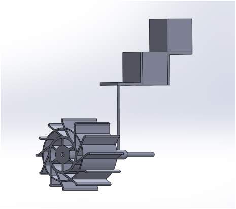 As both thrust and lift force were required to be measured, two separate force blocks were used in the experiment, force block X and Y. There were two steel L-brackets used to connect them together and force block Y would be mounted to a solid, non-moving wall to secure the whole set up. A bearing was used to connect the motor, shaft to the bracket and the paddlewheel. It was to be lubricated to minimize friction between motor shaft and it, therefore minimizing the interference of the force by the motor. Figure 13 shown the setup in Solidworks.
Figure 13. Proposed Experiment Setup
6.2 Force Block
The force sensors used in the experiment were essentially force blocks fitted with strain gauges that translate structural deformation induced into voltage. The thrust and lift forces were the main forces to be tested, therefore two blocks were needed for each directional force.
The main concern for the experiment setup at first were the presence of the motor. The motor was first decided to connect the paddlewheel using belt system to transmit input from the motor. However, it was found that bridging between wheel and supports would complicated the force direction and interfere the actual forces produced by the wheel therefore this idea was quickly turned down. Therefore, the motor would be connected to the wheel as a direct drive to simplify the setup.
A drawing of the force block planned to be used was included in the appendix showing key dimensions. The force block could provide an accurate reading up to 75N however, this was not expected to be reached as the force produced from the wheel should be much lower than that.
6.3 Variables
As the thrust and lift force was the main concern of this problem, number of variables would have impact on the magnitude of it. Therefore, it was sensible to theorize which would do so in this chapter.
6.3.1 Immersion Depth
As the magnitude of force produced by the paddlewheel depends on the immersed area, suggested by equation (3). The immersed area should be at its maximum to provide the biggest magnitude of thrust and lift force. Immersion ratio dictated the magnitude of force that would generate and the drag the wheel would face, the Volpich and Bridge suggested the optimal immersion ratio was at 0.15 with an efficiency of 85% (H. Volpich, I.C Bridge, 1955). However, their immersion depth was based on a propulsive paddlewheel only which would not agree with a paddlewheel that produced lift force as well. In Alexander work, it was pointed out that at the speed where the craft would ‘run’ on water, the paddlewheel would barely penetrate the surface of the water, suggesting that the lift and thrust force would be developed impulsively at the blade point of entry. (Alexander K. , 1983). This suggested that the maximum force developed would be smaller than that of Volpich and Bridge’s result. Therefore, it was sensible to use immersion ratio of 0.15 as a starting point and gradually decreasing it to locate a point where maximum forces were developed. The proposed testing points were included in table () for illustration with a wheel of 152mm in diameter. In the case where the maximum force was not reached, the immersion ratio could still be lower until it wasn’t physically possible. Table 7 shown the immersion ratio with different immersion depth.
Table 7. Immersion ratio with the corresponding immersion depth
| Immersion Ratio | Immersion depth (mm) |
| 0.15 | 22.8 |
| 0.075 | 11.4 |
| 0.0375 | 5.7 |
| 0.01875 | 2.85 |
| 0.009375 | 1.425 |
6.3.2 RPS
As lizard stride frequency is around 5Hz and 10Hz (S. Tonia Hsieh and George V. Lauder, 2004), choosing the corresponding RPS as a starting point for testing seems reasonable. Wray and Starrett pointed out that cavity intrusion, which was identified by Alexander, would occurred once the limit RPS has been reached by the paddlewheel (Wray, Gilbert A, Starrett, James A, June 1970). Due to this reason, the limit RPS should be identified during the experimental procedure by observing the water splash under slow motion where the blade of the wheel ‘hit’ the air bubble formed by the previous blade. However, this method would require the presence of a high-speed camera which would increase the budget. An alternative method could be simply by checking the thrust or lift against the RPS value. The thrust and lift value should increase with the increasing RPS. If cavity intrusion occurred, the increase of thrust of lift force would be smaller and would eventually reached to a steady state where any increase in RPS would not benefit the magnitude of force. In Alexander’s work, the maximum RPS was 12RPS which could be an identification of where the maximum force would be produced.
6.3.3 Flowing speed
The flow speed of the testing tank would also have to be determined due to the fact that the wheel would produce different magnitude of force at different speed of advance, which in this case the flow speed of the testing tank. And at the point where the flow speed get closer to the blade tip speed, would be where the maximum force, either thrust or lift, would be produced. The flowing speed would be limited by the tank and would have to be consulted before planning as the setting of the speed was believed to be fixed in the testing tank. Therefore, no suggested testing point was listed here.
6.4 Proposed Procedure
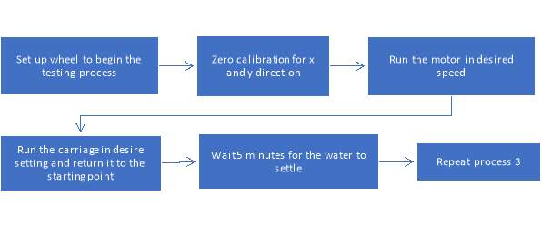
Figure 14. Proposed testing procedure in the tank
Figure 14 shown the recommended procedure to carry out in the towing tank. Immersion depth and rotation speed needed to be set before calibration as every change in immersion depth would affect the zero calibration therefore producing an offset in the result.
7. Discussion
7.1 Lift Force
A CFD model test was done to simulate one of the wheel to provide some understanding on the force acting on the water surface by the paddlewheel. A six-bladed wheel with a wheel size set to be 272mm in diameter, span of 76mm and immersion depth of 30mm with a flowing speed of 2.36m/s. This was chosen due to the ease to compare with Alexander’s CFD result.
Due to a short amount of time, only one 2D case was modelled. The simulation did not reach a steady state which was similar with that of Alexander’s case, discussed in chapter 2. The result was compared against Alexander’s result and plotted in Figure 15, some noticeable differences were observed between these results.
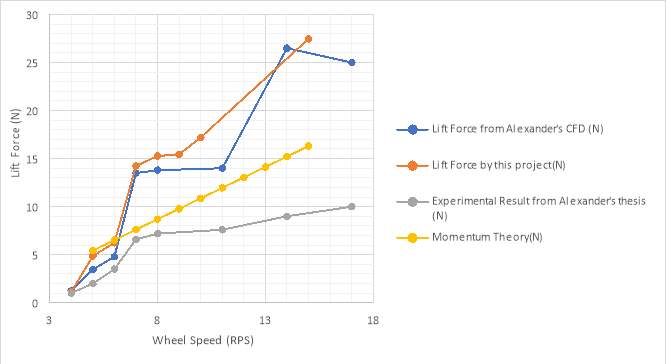
Figure 15. Comparison of lift force between Alexander’s CFD and this project’s
The general trend of this project’s CFD agree with what Alexander and Bowen did back in 2010 with some small discrepancies. These differences would be due to, as Alexander and Bowen suggested in their works (W.C. Bowen, K.V. Alexander, 2010), the number of elements in the simulation studies. The work that Alexander and Bowen conducted used approximately 400,000 elements to solve the VOF equation whilst this project only used around 300,000 elements therefore discrepancies were expected. In general, the higher the mesh quality, the accurate the simulation would be. In other words, the density of the mesh dictates the quality of the simulation. In Alexander and Bowen’s work, a study was done to investigate how the difference of mesh density affect the simulation, and shown in Figure 16 (W.C. Bowen, K.V. Alexander, 2010). With an improvement in quality, splashes could be monitored hence the accuracy of the simulation could be increase. Alexander’s experimental results were also included in the plot for comparison. A significant difference between results was seen because the numbers in the plot for CFD were average force in a 3 seconds interval during the simulation as no repeating force pattern was observed. Hence, averaged force was used to produce results.
The values generated from chapter 4 were also plotted into Figure 15. As it did not account for any drag, viscous and gravity effect, it provide a reasonable estimate of the lift force within the lift force from CFD and from Alexander’s experiment
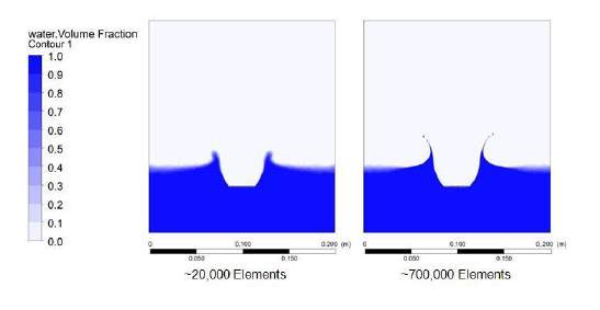
Figure 16 Variation in simulation with different number of elements. (W.C. Bowen, K.V. Alexander, 2010)
The main problem of this analysis was the complexity of how splashes would interact with splashes generated by a previous blade. Figure 16 demonstrated the difference amount of element, and how they would have generated a different image of water splash. These results simulate a blade dropping directly into the water, and with the 700,000 case the water splashes were finer than the one with 20,000 elements. These differences would produce some discrepancies in the result against their works.
Using the preliminary hull design data in Chapter 3, assume the model would be made from FRP as recommended in ITTC procedure. (ITTC, 2011) The density of a FRP would be somewhere around 2000kgm-3. Based on the preliminary model design the weight would be 4.07kg, which is equal to 39.93N assuming g = 9.81ms-2. With four paddlewheels the total lift force at 7RPS would be 56.96N, which would be more than enough to lift the hull of the surface therefore reducing the drag.
7.2 Performance against other high-speed crafts
The significant advantage of a lifting paddlewheel craft over hydrofoil and planning hull is that both type of crafts would need a deep draught, either for the screw propeller or the foil to operate underwater. Lifting paddlewheel craft would only need the draught from the paddlewheel which would be operating near water surface, and once it lifts off from the surface, almost no draught is needed, which make it favorable over those crafts to be used in shallow water.
Another advantage that a lifting paddlewheel craft could have the potential to operate on road, making it an amphibious vehicle, whilst ACV need a smooth surface to travel on, inclined road would not be beneficial for ACV operation. (Alexander K. , 1983)
8. Conclusion
There were number of difficulties when trying to conduct this project and as a general conclusion this project was as successful as it would be. Facing the limit budget and resources available, the outcome was not satisfactory and future works were suggested to be done where model could be manufactured and tested in a tank. A head time of 3 months was recommended to design the wheel and iterated until it was printed as structure could be impossible to print without supporting layer and time would be needed to remove any additional support structure for the 3D printing process.
The experiment conducted by Alexander was much more mature than this project, due to reasons that he dedicated a large amount of time into the idea of a lifting paddlewheel and developed several model crafts to test. Multiple variables and setting were tested in his prototype craft, such as spray deflectors to increase lift not different from a planing hull. Air guard over the paddlewheel was also suggested in his work where the drag in air would be lower. (Alexander K. , 1983)
Few improvements to this project are suggested and listed below:
- 3D printing to manufacture the wheel could prove to be an iterative way and more time consuming than hand made it. Several designs were needed to produce before entering the manufacturing stage.
- The difference between a belt mounted system and direct drive should be investigated as Alexander’s result were based on a belt drive system which could potentially affect the results as force would acted upon difference directions, and therefore the magnitude of force would be different.
- A 3D CFD analysis could be done to improve the accuracy of CFD analysis, as 2D CFD simulation did not reach a steady state within the modelled time duration.
However, some findings proved to be useful and are listed below:
- A basis of paddlewheel theory was established and would be useful for future research.
- Velocity ratio needs to be monitored closely as cavity intrusion would affect the efficiency of the wheel.
- CFD result shown a reasonable lift force that would enable it to lift a hull out of the surface and to ‘run’ across.
- Design of the wheel has been iterated to be 3D printed ready. Future project could use these design for testing.
These findings have shown that a lifting paddlewheel was theoretically possible and would be beneficial in certain scenario such as shallow water and possibly on road. The operating style of the paddlewheel would also be simple as other type of vessel and easier than an ACV since it would not need any other special training. The potential problem of employing a paddlewheel system would be its large change in draught, and in rough weather the paddlewheel efficiency would be lower than that of a screw propeller as the wheel would rise out of the water decreasing the contact area with water, whilst a screw propeller would constantly be in contact with it.
This project has shown that the limit of paddlewheel has yet to be found and a lifting paddlewheel system would be plausible. Further researches are recommended explore such as:
- Construction of a model size lifting paddlewheel craft to test in a towing tank for its speed and therefore a graph of power versus speed could be plotted and compare against hydrofoil, ACV and planing hull.
- Compare the difference between six-bladed paddlewheel and twelve-bladed paddlewheel. The main difference should be the limit RPS for cavity intrusion where six-bladed could used a higher RPS than that of a twelve-bladed wheel.
- Derived a more detailed theory on the impulsive force generated by the flat blade paddlewheel as well as curved blade.
- Investigate the possibility of employing a feathering wheel in high RPS to test if the feathering wheel could optimize the angle of entry in high speed.
The problem on paddlewheel was the interaction between the blade and the water surface which has not been handled in depth and lack of a comprehensive theory to explain flow around the blade. Further work and research would benefit to develop this theory which in turn would aid paddlewheel as a propulsion method back into the modern world, either being a specialized river transport or an automatous survey model.
References
Alexander, K. (1983). Prototype model tests of a high speed wheeled amphibious vehicle. New Zealand: Department of Mechanical Engineering, Melbourne School of Engineering.
Alexander, K. V. (1983, January 01). The lifting paddlewheel : a non-buoyant wheel enabling a high speed wheeled amphibious craft to run on the water surface. New Zealand: University of Canterbury. Mechanical Engineering. Retrieved from UC Research Repository.
Ansys, I. (2017). Ansys CFX. Release 18.1.
Cain, P. (2018). 3D Hubs. Retrieved April 02, 2018, from https://www.3dhubs.com/knowledge-base/supports-3d-printing-technology-overview
Crewe, P.R., Eggington, W.J. (1960). The Hovercraft – a new concept in maritime transport. Trans R.I.N.A., 315, 102.
H. Volpich, I.C Bridge. (1955). Paddle wheels Pt. 1: Preliminary Model Experiments. Scotland: The Institution of Shipbuilders and Engineers of Scotland.
Harish, A. (2018). Simscale. Retrieved April 21, 2018, from https://www.simscale.com/blog/2016/10/what-is-finite-element-method/
Hyun Soo Park, S. Floyd, M. Sitti. (2008 ). Dynamic modeling of a basilisk lizard inspired quadruped robot running on water. IEEE/RSJ International Conference on Intelligent Robots and Systems, 3101–3107.
ITTC. (2011). ITTC – Recommended Procedures and Guidlines. Ship Model.
Matsson, J. (2010). An Introduction to SolidWorks Flow Simulation. SDC Publications.
Professors R A Shenoi and R V Pomeroy, Mrs. G A Keane and Dr. D J Taunton. (2017). SESS2017 Ship Desgin and Economics. University of Southampton.
S. Tonia Hsieh and George V. Lauder. (2004). Running on water: Three-dimensional force. Proceedings of the National Academy of Sciences, 101(48), 16784-16788.
Solidwork 2016. (n.d.). Dassault Systèmes.
Steven Floyd, Serhat Adilak, Steven Ramirez, Raphael Rogman, Metin Sitti. (2008). Performance of Different Foot Designs for a water running robot. CA, USA: IEEE Internation Conference on Robotics and Automation.
W.C. Bowen, K.V. Alexander. (2010). CFD on High Speed Paddlewheel. Auckland, New Zealand: University of Canterbury, Christchurch.
Wray, Gilbert A, Starrett, James A. (June 1970). A model study of the hydrodynamic characteristics of a series of paddle-wheel propulsive devices for high-speed craft. New Jersey: Davidson Laboratory.
Appendix
Appendix 1 – Force Block Drawing
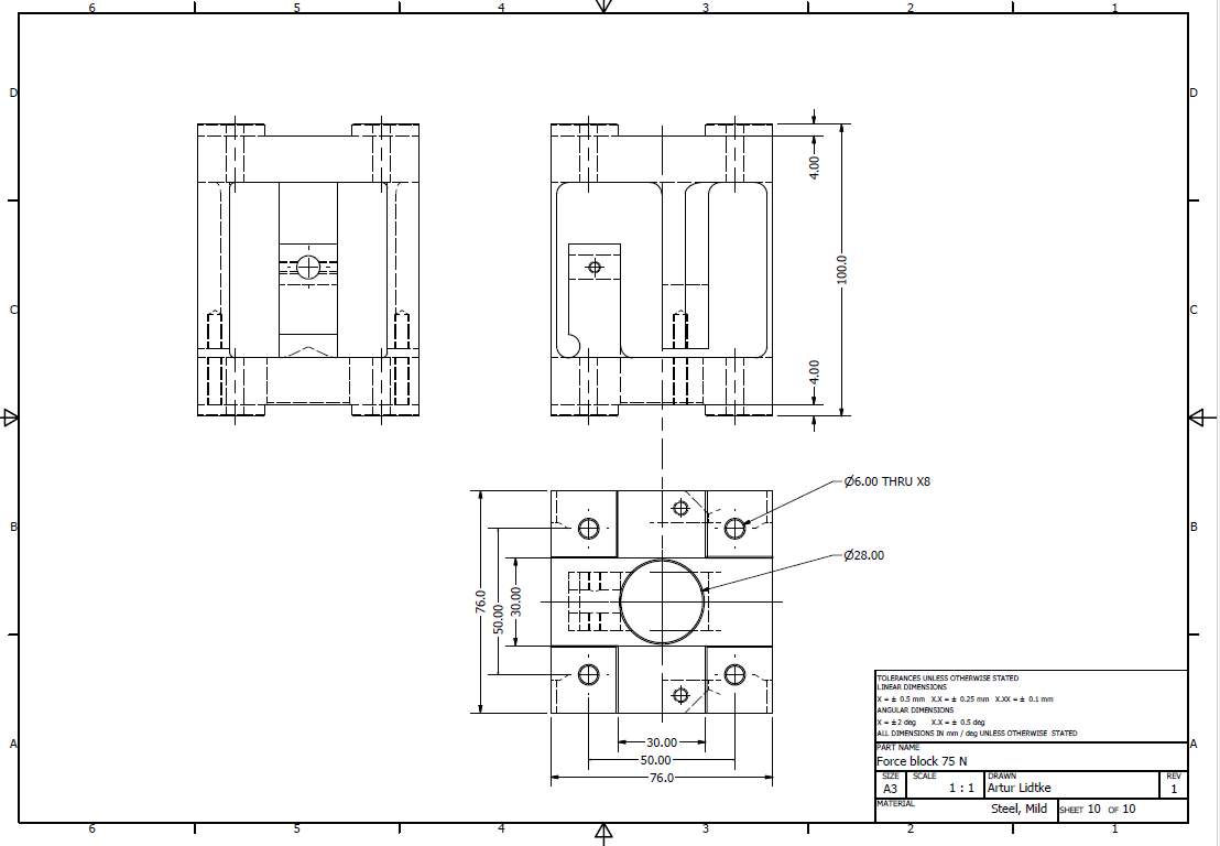
Figure 17 Force block that this project intends to use
Appendix 2 – Wheel Designs
Curve twelve-bladed paddlewheel model with drawing.
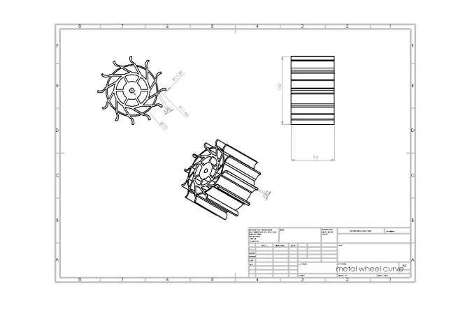 Figure 18 Model of the curved blade paddlewheel
Figure 19. Drawing of the curved blade wheel
Cite This Work
To export a reference to this article please select a referencing stye below:
Related Services
View allRelated Content
All TagsContent relating to: "Maritime"
Maritime is something relating to the seas and oceans. The term is commonly used in nautical and seaborne trade matters. Not to be confused with “marine” which relates specifically to the seas, oceans and the life within them.
Related Articles
DMCA / Removal Request
If you are the original writer of this dissertation and no longer wish to have your work published on the UKDiss.com website then please:

