Design for a High-Temperature Thermal Storage Vessel Coupled to a Free-Piston Stirling Engine
Info: 7457 words (30 pages) Dissertation
Published: 10th Dec 2019
Tagged: EngineeringMaritime
Novel Flexure Design for a High-Temperature Thermal Storage Vessel Coupled to a Free-Piston Stirling Engine
Abstract
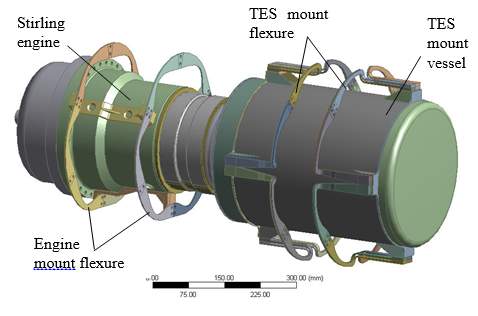
A novel support flexure for a salt-based thermal energy storage (TES) vessel coupled to a solar dish Stirling engine was designed and analyzed via Finite Element simulations. During normal operation, the TES vessel experiences significant thermal expansion as a result of the high temperatures experienced. This leads to a large deformation and high thermal stress along with a large temperature gradient within the flexure. Eight flexures are arranged symmetrically around the circumference of the salt vessel. The designed flexures have an axial and circumferential section that allows for the vessel to expand in both the radial and axial directions. Additionally, the flexures can be stacked to increase the lateral rigidity to prevent the vessel from sagging under gravitational effects while still allowing for the desired axial flexibility. Because of the high temperatures experienced by the flexure, the superalloy Inconel 625 was used as the flexure material. In addition to a model of just a single flexure, a system scale model that included the flexures, a dummy engine, and the TES salt container was developed. The results of the analysis showed that the final flexure design meets the stress, deformation, and fatigues requirements. The chosen design is compact, simple, low-cost, and can potentially be used in other applications where a support structure experiences a high degree of thermal expansion.
INTRODUCTION
Owing to the increased concern over the detrimental environmental effects of burning fossil fuels coupled with their ever-dwindling supply has spurred renewed interest in clean sustainable alternatives. Of particular interest is that of solar energy for grid scale electrical power generation. The most promising method for converting solar radiation into useful power is via a concentrated solar power (CSP) plant. At a CSP plant, the incoming solar radiation is used to heat a working fluid within a thermodynamic cycle. Typically CSP plants are broken down into three categories based on the type of receiver used; power tower, though, and parabolic dish. A trough type receiver can achieve a concentration of around 75 suns at temperatures around 400 °C whereas a power tower receiver has a concentration of 800 suns at 560 °C. Although it is the least used receiver a parabolic dish type receiver has a concentration of 3000 suns at temperature nearing 750 °C [1–4]. Traditionally, a Stirling engine is placed at the focal point of a parabolic dish to convert the thermal energy into electricity. Of the various solar electric technologies, the Stirling dish converters have the highest solar to electric conversion efficiencies where the heat to electricity efficiency of the state of the art Stirling engines are approximately 40% [3, 5]. Research into Stirling dish solar power has been in development for over 20 years however it is still underutilized [1–3,5,6]. In Stirling dish systems, the solar energy is focused on the hot end of a Stirling engine where the energy is absorbed by the working fluid. Unlike the Otto and Diesel engines, Stirling engines are external combustion engines which allow for them to easily be run off a variety of fuels, such as solar energy, as long as the required temperature is met. While most Stirling dish systems use a kinematic Stirling engine, a more reliable option is to use a free-piston type engine. In a kinematic Stirling engine, the power piston and the displacer are mechanically linked whereas in a free-piston engine the pressure variations within the working fluid are what cause the reciprocating elements to move. The lack of manual linkages and the use of clearance seals in a free-piston engine increases both its lifespan and reliability making it an ideal choice for use in a remote solar field. A prime example of a state of the art Stirling dish solar converter is the Infinia Corp. PowerDish™ which integrated a 3-kW free piston Stirling engine (FPSE) that uses unique flexure bearings, clearance seals, has no wearing parts, and no lubricants to result in a maintenance-free design life of 150,000 hours [7].
Despite its attractiveness, the inherently transient nature of solar energy has kept it from becoming widely used as it is not cost competitive with the traditional fossil-fuel based power plants. In order for a solar power plant to generate electricity during cloud transients or off sun hours, a form of energy storage is required. At a CSP plant, thermal energy storage (TES) can easily be integrated such that excess solar radiation can be stored for later use, thus increasing the number of hours at which the CSP plant can efficiently operate. There are three types of TES systems that can be implemented at a CSP plant: sensible heat, latent heat, and thermochemical energy storage systems. These systems are defined based on the principle of energy storage. Currently, the majority of TES implemented at CSP plants around the world are molten salt sensible heat storage systems at either a trough or central receiver type plant [8,9]. These systems require a large volume of storage material as well as insulated storage tanks to minimize heat loss and system freezing that would result in a total system shut down. By utilizing a latent heat or thermochemical energy storage system the volume of storage material required to store the same amount of energy is immensely reduced. A wide range of both organic and inorganic materials have been investigated as potential phase change materials (PCM) including paraffin wax, fatty acids, sodium nitrate, potassium nitrate, sodium nitrate-potassium nitrate eutectics, sodium chloride, solar salt, mineral oil, synthetic oil, silicone oil, carbonate salts, and liquid sodium [8,10–12]. Nonetheless, using PCM for TES presents several unique difficulties. Most prominently the low thermal conductivity of the studied materials since as the PCM solidifies it adheres to the heat exchanger and has a limiting effect on the energy discharge process. Additionally, material compatibility between the PCM and the TES module is a prominent design factor. A variety of sources exist in the literature that presents the results of corrosion testing of different combinations of PCM and TES modules [13–17].
While TES has been employed at operational CSP plants, there are virtually no cases of it being incorporated with a Stirling dish system. To provide electricity during cloud transient and non-daylight hours, A TES module that contains a thermal salt-based PCM will be incorporated into the Infinia PowerDish™. The TES system uses PCM salts of high melting points (600-700 °C) to maximize the energy storage density by utilizing both the latent heat and sensible heat over large operating temperatures and to provide sufficient extra thermal energy for 4 to 6 hours of operation. For the heat fluxes required for a Stirling dish system, highly conductive fins are unsuitable and therefore a heat pipe based system will be used. A significant challenge for the TES system is the design of the flexures that will support the cylindrical TES salt vessel owning from the thermal expansion of the vessel in both the axial and radial directions due to the large temperature difference experienced. During normal operation, since the two ends of each individual flexure are anchored to the vessel (~650 °C during operation) and dish frame (~ambient temperature) respectively, there is a large temperature change along the flexure itself, yielding a severe thermal stress. Also, the flexure needs to be axially compliant to allow engine/vessel axial vibration motion and laterally rigid to avoid large displacement under gravity. In addition, the flexure is desired to have a low manufacturing cost. Over the course of the design process, numerous flexure designs were evaluated using Finite Element Analysis (FEA).
Many sources can be found in the literature concerning FEA analyses of planar springs intended for the use I Stirling convertors, cryocoolers, linear alternators, etc. [18–25], although these analyses usually do not include temperature considerations due to the flexure’s function in the system. Al-Otaibi and Jack [18] utilized a static FEA analysis to optimize the design of a spiral flexure hearing for a reciprocating linear motor. Zhou et al. [19] used FEA to study the stress and displacement of an Oxford and triangle flexure and their results indicated that the triangular flexure design had a larger radial to axial stiffness ratio and a higher natural frequency. Rajesh and Kuzhiveli [20] parametrically studied a flexure used in a cryocooler by examining the effects of the spiral sweep, angle, slot width, number of spirals, and flexure thickness. Malpani et al. [21] used FEA to determine the axial stiffness of a spiral cut flexure bearing for use in a linear compressor. Khot and Gawali [22] used a nonlinear static structural FEA approach to optimized the geometry of both a spiral and linear flexure bearing. Prasad et al. [23] conducted a parametric analysis of a spiral arm eccentric flexure to optimized the shape factor using FEA. Chen et al. [24] developed an FEA model to as a way to verify their parametric analysis of a spiral flexure spring. Yun et al. [25] used FEA to design a planar spring for a Stirling convertor and then verified the numerical predictions using experimental stress results. Gaunekar et al. [26] used FEA to evaluate a flexure design for use in a high precision lens focusing mechanism. Calvet et al. [27] designed a square flexure system for use in miniature cameras and other similar devices. Howell et al. [28] designed an ortho-planar intended for valve opening purposes. Lee et al. [29] presented the design of a superconducting relative gravimeter that utilizes a planar spring as a key component. Qi et al. [30] reported on the design of a continuum manipulator that involved planar springs and Sugandi et al. [31] reported the fabrication of a square planar spring for an electrodynamic vibration energy harvesting application.
While there are numerous examples in the literature of the various applications for planar springs or flexures, few account for thermal gradients within the flexure. Given the vast body of work on using FEA to design flexures, a new method was developed that incorporates thermally induced stresses that can occur in high-temperature applications such as those that occur in Stirling CSP applications. In addition to the inclusion of the thermal stress, the designed flexure needs to be laterally rigid while being radially compliant all at low cost. The proposed TES flexures were simulated at two levels: a single flexure with 1/16th of the vessel and a system scale model that included flexures, the salt TES vessel, and a dummy engine. The results of this investigation extended the already documented FEA analysis of flexures to include thermal stresses.
Nomenclature
CSP Concentrating Solar Power
FEA Finite Element Analysis
FPSE Free‑Piston Stirling Engine
PCM Phase-Change Material
TES Thermal Energy Storage
system Design
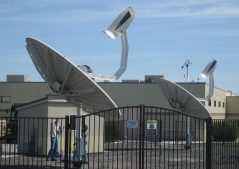
The TES system consists of a cylindrical salt vessel that is welded to the heater head of a 3 kW Infinia FPSE. The engine and TES vessel are fixed to the receiver dish frame at ambient temperature via flexure springs. These springs allow for certain axial engine case vibration and reduce the transmissibility of the vibrational forces of the Stirling engine. The flexure springs, as well as two operational Power Dish units without TES incorporated, are shown in Figure 1. For the new system design, the existing stainless steel 304 planar engines mount flexures are used as the support for the 3 kW engine. However, in contrast to the engine, one end of the storage vessel flexure is fixed to the hot vessel enclosure and therefore has an elevated temperature of ~650 °C during operation. Not only is stainless steel not suitable for use at this temperature, the existing planar engine flexures are too rigid in the radial direction to allow for the thermal expansion they will experience. Therefore, new flexures must be designed to support the TES salt container. The flexures will be designed to have (1) a relatively large lateral rigidity as to only allow small amounts of vessel sagging or tilting under gravitational effects; (2) the axial flexibility to allow for the axial vibrations resulting from the case motion of the engine assembly; (3) the stress field within the flexure will meet the stress, fatigue, and creep requirements; (d) low thermal conduction loss through the flexure mounting; (e) the flexures will be low cost, compact, geometrically simple, and easy to assemble. A design that has all of these attributes is difficult to achieve. Additionally, a major design obstacle is to reduce the high thermal stresses that result from the radial and axial thermal expansion of the storage container as well as the large temperature gradient along the flexure.
 |
 |
| Figure 1 – Left: Two Infinia 3 kW solar dish units without TES during on-sun operation. Right: Vessel and engine flexures with the salt vessel-engine assembly. | |
As the storage vessel-engine assembly is largely symmetric, a natural assumption is that several individual flexures of the same shape can be arranged circumferentially to obtain the desired effects. Multiple design concepts were studied and compared which included a bolted flexure design in which the axial and circumferential flexure comments are bolted together and a one where the TES vessel is hung within a frame using coil springs. Analysis showed that the bolted design yields excessively high stress near the bolting region resulting from the thermal expansion. For the hanging design, a suitable coil spring or low-k spacer that can work at 650 °C with a suitable lifespan could not be found. The current working concept that will be investigated is that of using a single-piece flexure design that has a section placed along the vessel’s axis and a section in the circumferential direction. It is expected that the axial section will allow for the vessel’s radial deformation, while the circumferential sections allow the vessel to expand thermally in the axial direction and will also provide the required axial compliance. By optimizing the dimensions of the flexure, one can obtain the required rigidity in the lateral direction or this can be accomplished by using stacked flexures.
Over thirty design iterations of the above concept were evaluated using FEA and several are shown in Figure 2. The flexures shown in Figure 1 consists of 2 sets of 8 symmetrically distributed L-shaped flexures, bottom right of Figure 2, on the surface of TES container. The two flexures are 100 nm a part. These particular flexures are a thin flap that bends into a 90° angle that forms the two desired sections. These flexures were 3.566 mm thick in the axial section and 2 mm in the circumferential section. For this particular design, two flexures were stacked to increase the lateral rigidity. The L-shaped flexure design has several merits as the design is compact and simple and allows for expansion in both the axial and radial directions. Furthermore, the axial section of the flexure has a small width that allows for a certain amount of twist deformation that therefore releases the stress and also has as relatively small conduction losses. The final chosen design resembles an upside-down number 7, bottom left of Figure 2, which is wider to more evenly distribute the stress. Inconel 625 (Solution Annealed, sheet, 60Ni-22Cr-9Mo-3.5Cb) was used as the material for the flexures due to the high temperature they experience. The temperature-dependent physical material properties were taken from the ASME Boiler and Pressure Vessel Code, Section II, Part D and the fatigue properties were taken from Section III, Appendix I for nickel-chrome-iron alloys [32].
 |
 |
 |
 |
| Figure 2 – Evolution of TES container flexure supports from version one counterclockwise to the final chosen design | |
Design criterion
Stress
Section VIII, Division 2 of the ASME Boiler and Pressure Vessel Code was used to set the design criteria [32]. The allowable tensile stress was based on the ASME allowable design strength, Sm, for Inconel at various temperatures, the entire design curve is shown in Figure 3. The allowable stress values shown in Figure 3 from the ASME code use a factor of safety of 1/3.5 on the ultimate stress at room temperature and 1.1/3.5 at elevated temperatures. Additionally, a value of 2/3 is used on yield stress. Furthermore, at elevated temperatures, a safety factor of 2/3 is used on the creep to rupture strength and the 1% creep strength is used without a safety factor.
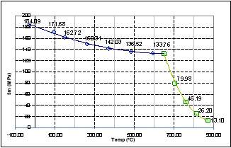 |
| Figure 3 – Allowable Stress vs. Temperature for Inconel 625 |
The primary membrane stresses, Pm, were checked against the basic material strength. The membrane stresses near discontinuities were considered as local membrane stresses, PL, and were allowed to be 1.5 times Sm. The primary membrane stress plus the bending stresses, PL+Pb, at the surfaces were also limited to be under 1.5Sm. Primary plus bending plus secondary stresses, PL+Pb+Q, should be less than 3Sm. The allowable stresses at elevated temperatures are intended to limit creep to such a degree that it is negligible. The temperature experienced by the part is within the range permitted by Section VIII, although the material is a Division 1 material that is using used in a division 2 analysis.
Fatigue
Due to the case motion of the Stirling engine, the flexures undergo a high cycle fatigue. The number of pressure cycle required in the design is 1.5×10¹⁰ cycles based on an engine frequency of 60 Hz, 8 hr/day operation, and a 25 year lifetime. Additionally, the flexures experience a low cycle fatigue due to the variation in the secondary stress field during thermal cycling resulting from start-up and cool down. Assuming three starts per day, the load results in 27,000 cycles. The stress per cycle, S-N, curves for Inconel 625 are shown in Figure 4. Note that Figure 4indicates that for Inconel 625, the high-temperature and room-temperature fatigue strength. Sa, is close for large N, N>107. Therefore, Figure 3 can be used for the high cycle fatigue loading. The Goodman criteria were also used to account for the combined effects of mean loading and fatigue loading. For Inconel 625 sheet, axial load, Kt=1, Sa = 270 MPa for N=2.9×10⁴ and Sa = 135 MPa for N=1.5×10¹⁰. The fatigue loading a for Inconel 625 is presented in Table 1.
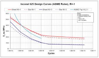 |
| Figure 4 – Infinia S-N Curves for Inconel 625 |
Table 1 – Fatigue Value of Inconel 625 (Kt = 1)
| From ASME, ASMH, and Mil Handbook | Cycles | Sheet KT=1
Sa (MPa) |
| LC Fatigue | 27000 | 270 |
| HC Fatigue | 1.5×10¹⁰ | 135 |
Displacement
As the flexure is desired to be axially flexible and laterally rigid, the static sag resulting from gravitational effects is desired to be less than 0.5 mm.
Results and discussion
The various flexure designs were analyzed using FEA within Ansys. First, the steady state temperature was analyzed and then used as the input to a structural analysis. A linear-elastic evaluation was used and therefore no plastic deformation of the material was considered. A simplified 1/16th model was first analyzed to provide information on the heat loss and spring constants in the axial, radial, and circumferential directions. After this, a system scale model that included an engine, salt container, TES flexures, and engine flexures was analyzed.
Analysis of Single Flexure
Thermal Analysis
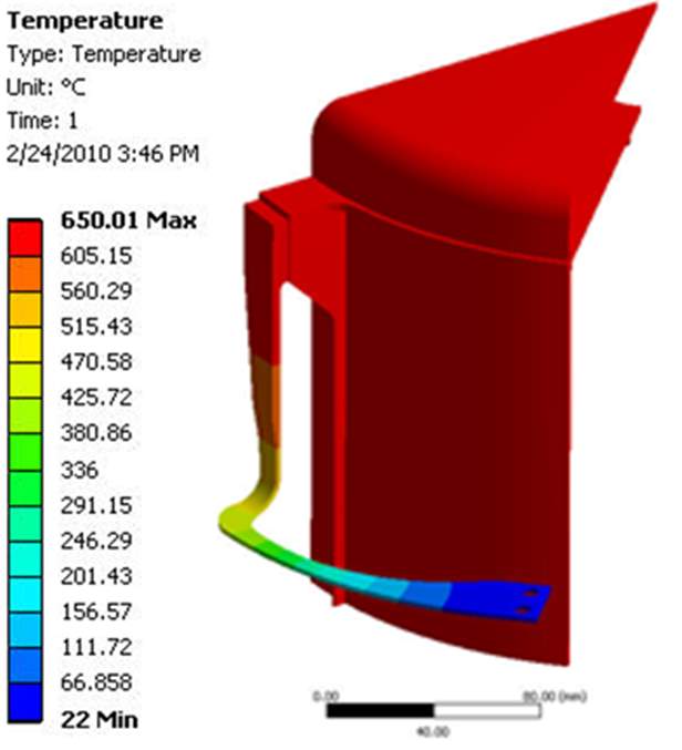
Due to the symmetry of the system, a 1/16th model that includes a single flexure without the Stirling engine was used for the initial model. For the thermal analysis, the boundary conditions were a temperature of 650 °C applied to the interior of the TES container and 22 °C applied to the fixed end of the flexure. Figure 5 shows the predicted steady state temperature distribution for both the L-shaped and inverted 7-shaped flexure designs. The temperature gradient within the inverted 7-shaped flexure is slightly smoother than that within the L-shaped flexure. The results showed that for the L-shaped flexure the conduction heat loss for a single flexure is 1.7 W, therefore the total heat loss is 27.2 W for the entire system and thus can be ignored. (this information isn’t in the final report for the chosen flexure and I don’t know how to calculate it.)
 |
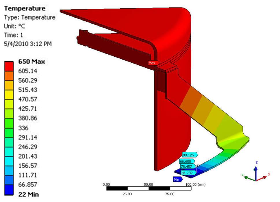 |
| Figure 5 – Temperature distribution for the L-shaped (left) and inverted 7-shaped (right) TES flexure designs | |
Structural Analysis
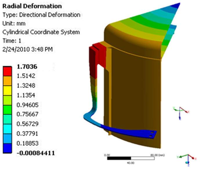
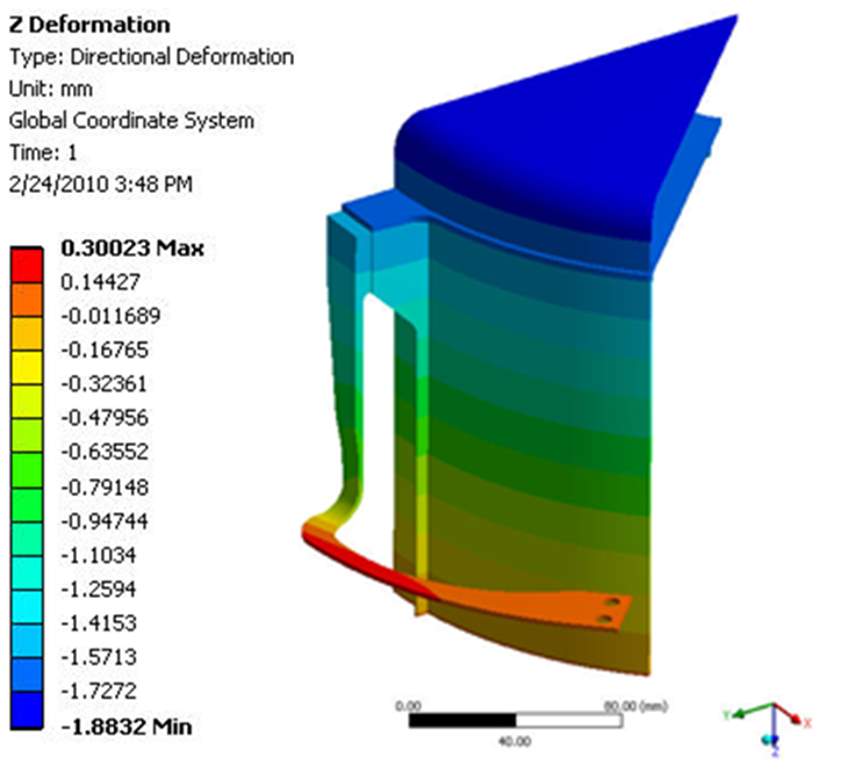
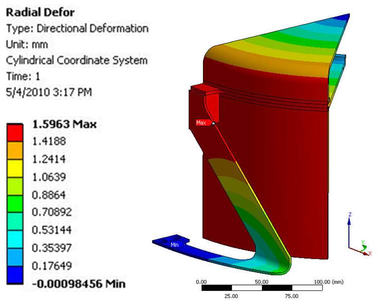
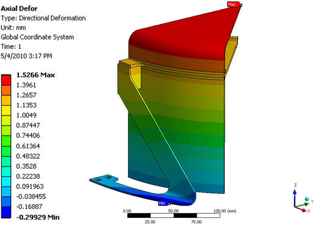
The calculated temperature distribution was used as the thermal input to a structural analysis where the cold end of the flexure is fixed in space and symmetric boundary conditions were applied where required. As no mechanical load was applied, the resulting stresses are purely thermal stresses or secondary stresses. The stress prediction is just a guide for the flexure design process. Additionally, mechanical loading will be applied to the system scale investigation discussed later. The predicted axial and radial deformation resulting from thermal stresses for both flexure designs are shown in Figure 5. For the L-shaped flexure, a deflection of 1.7 mm and 1.88 mm was predicted in the radial and axial directions respectively. For the inverted 7-shaped design, the radial deflection is 1.6 mm and the axial deformation was 1.5 mm. The predicted results are consistent with the closed-form estimate using the average thermal expansion coefficient and the temperature change of the container.
 |
 |
 |
 |
| Figure 5 – Radial (left) and axial (right) deformation for the L-shaped (top) and inverted 7 (bottom) TES flexure designs | |
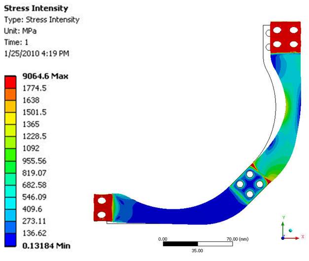
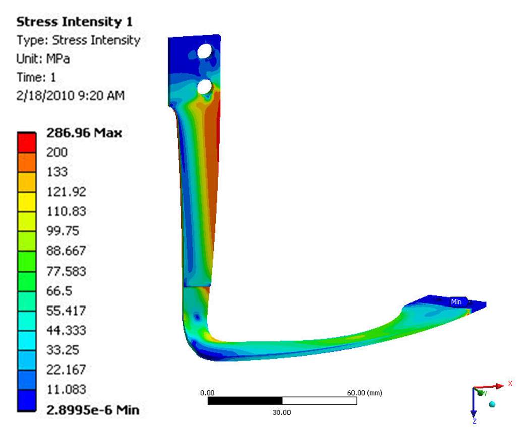
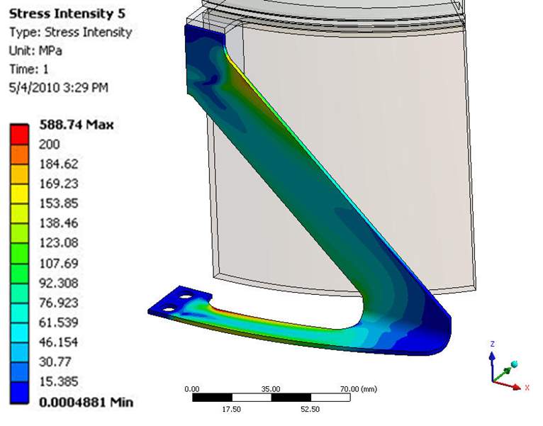
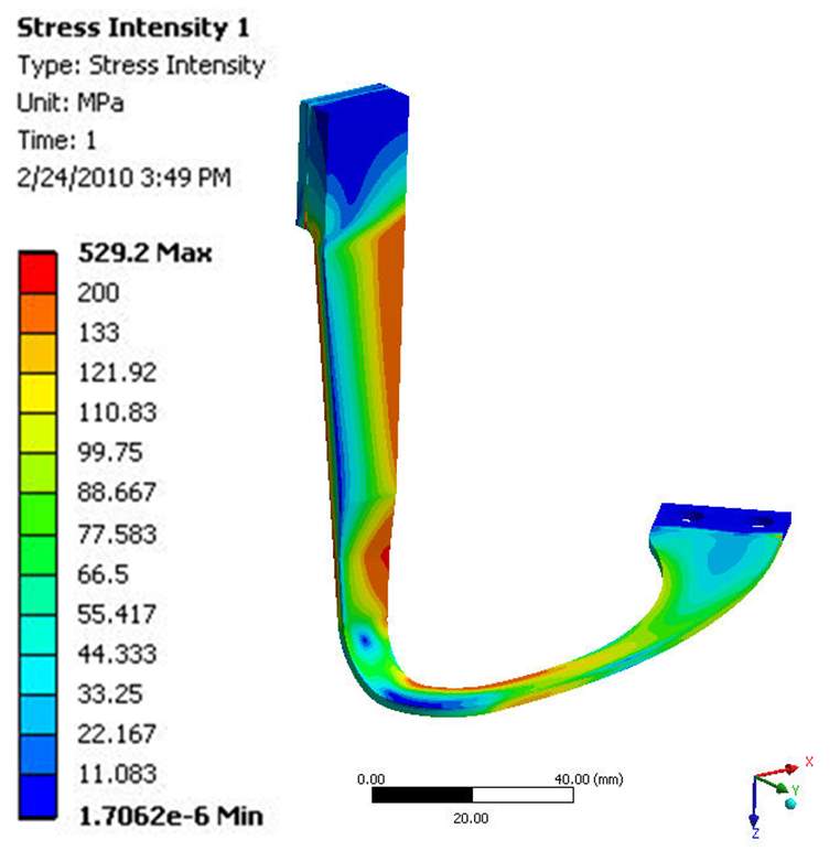
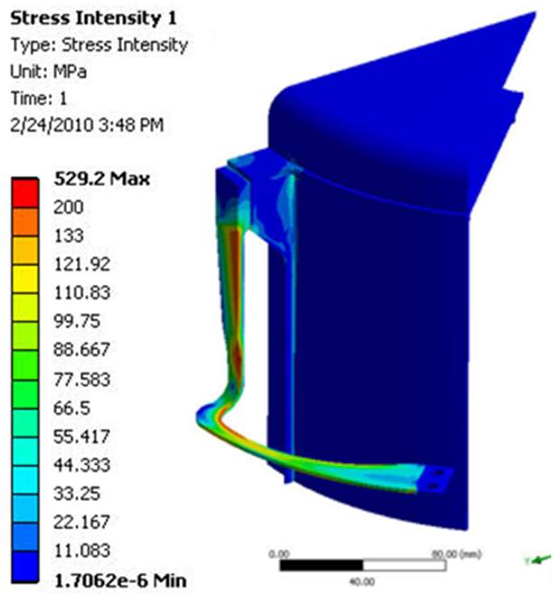
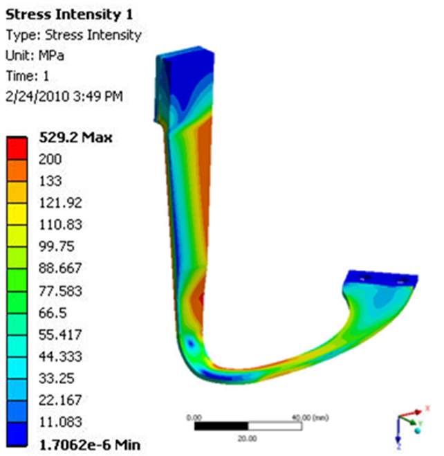
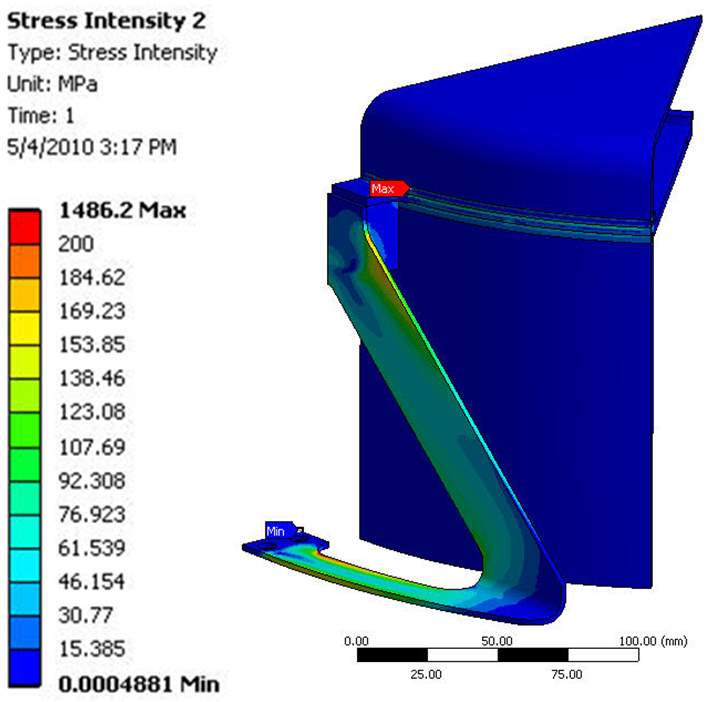
During the initial design stages, the flexure had a uniform 3 mm thickness, however, FEA results indicated a high stress near the hot end of the axial section. Therefore, for the L-shaped flexure, a non-uniform thickness was used with a 3.566 mm and 2 mm thickness in the axial and circumferential sections. This allows for the high stress in the axial section to be spread into the lateral section. (The thickness of the inverted 7 flexure is not listed in the final report) The stress field within the container/flexure is shown in Figure 7. As with the temperature distribution, the stress in the inverted 7-shaped flexure is more evenly distributed than in the L-shaped flexure. In both cases, the max stress within the flexure arm is approximately 200 MPa. For the L-shaped flexure, the max membrane stress is 52.3 MPa which is less than Sm and the max surface stress is 200 MPa which is less than 3Sm. (again this information is not presented for the chosen flexure design and I do not know how to calculate it from the photos) Therefore, the stress within both flexure designs is within the design criteria. However, note that both the effects of gravity and engine coupling have been ignored in the current model.
 |
 |
 |
 |
| Figure 7 – Stress field for the L-shaped (top) and inverted 7 (bottom) TES flexure designs | |
The axial, radial and the lateral spring constant of the TES flexures were simulated using the 1/16th single flexure model. The results were then compared to the engine mounting flexures, Table 2. For the analysis, the reaction force under a small displacement load was calculated to obtain the spring constant. The predicted axial spring force, axial, for a single L-shaped flexure is 32.58 N/mm which is comparable to the value of the engine mount flexures. The results for the lateral and radial spring constants, however, are an order of magnitude less than those for the engine flexure. Despite this, it is believed that the flexures are rigid enough. It was estimated that the static deformation of the engine flexure due to gravity is 0.0083 mm. The static deflection for the 65 kg salt container is 0.09 mm which is negligible. This estimate is based on the lateral spring constant of only four TES flexures, thus the estimate is conservative.
Table 2 – Predicted spring constant of a single vessel and engine flexure (m_vessel=65 kg; m_engine=85 kg)
| Unit | TES Flexure (single) | Engine Flexure (single) | |
| kaxial | N/mm | 32.58 | 27.8 |
| kradial | N/mm | 13.49 | 7868 |
| klateral | N/mm | 862.84 | 12585 |
| Sag by gravity | mm | 0.09 | 0.0083 |
System Model
In order to obtain more accurate results, a system scale model that consists of the salt container, TES flexures, engine, and engine flexures was constructed. In this model, the TES vessel was welded to the heater head of the FPSE. In an effort in increase the lateral and radial rigidity, two TE s flexures were stacked together. It is believed that using stacked flexures will not change the stress field significantly as the majority of the stress is thermally induced but it will double the effective rigidity of the flexure. In the model, both the engine body and engine flexures were taken to be stainless steel 304, while the heater head was Inconel 625 due to the high-temperature requirements. It is expected that the system model will reveal the interactions between the engine and salt vessel flexures as well as provide more accurate stress and deformation results.
Thermal Analysis
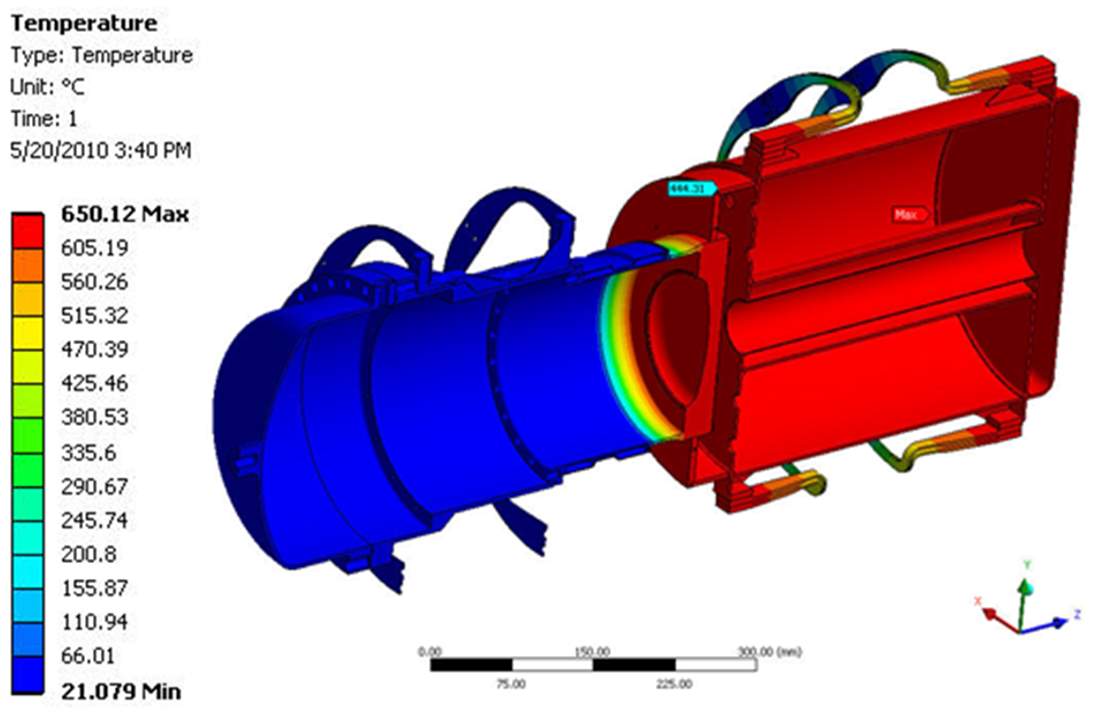
As with the single flexure model, first, a temperature field was calculated. Only half of the engine was modeled due to symmetry. As with the previous model, the inside temperature of the TES vessel is set to 650 °C and the cold end of the Stirling engine body is 22 °C. The temperature distribution is shown in Figure 8. The predicted heat loss was 54.9 W.
 |
| Figure 8 – Temperature distribution within the entire Stirling engine TES system |
Structural Analysis
The above temperature distribution was used as the input to the structural analysis along with a gravity force of 85 kgf and 65 kgf applied to the center of gravity of the Stirling engine and TES container respectively. The cold end of both the engine and TES flexures are fixed. The internal pressure inside the engine was not applied since it has a negligible impact on the flexures and it results in a numerical error in the axial displacement as the flexures are very compliant.
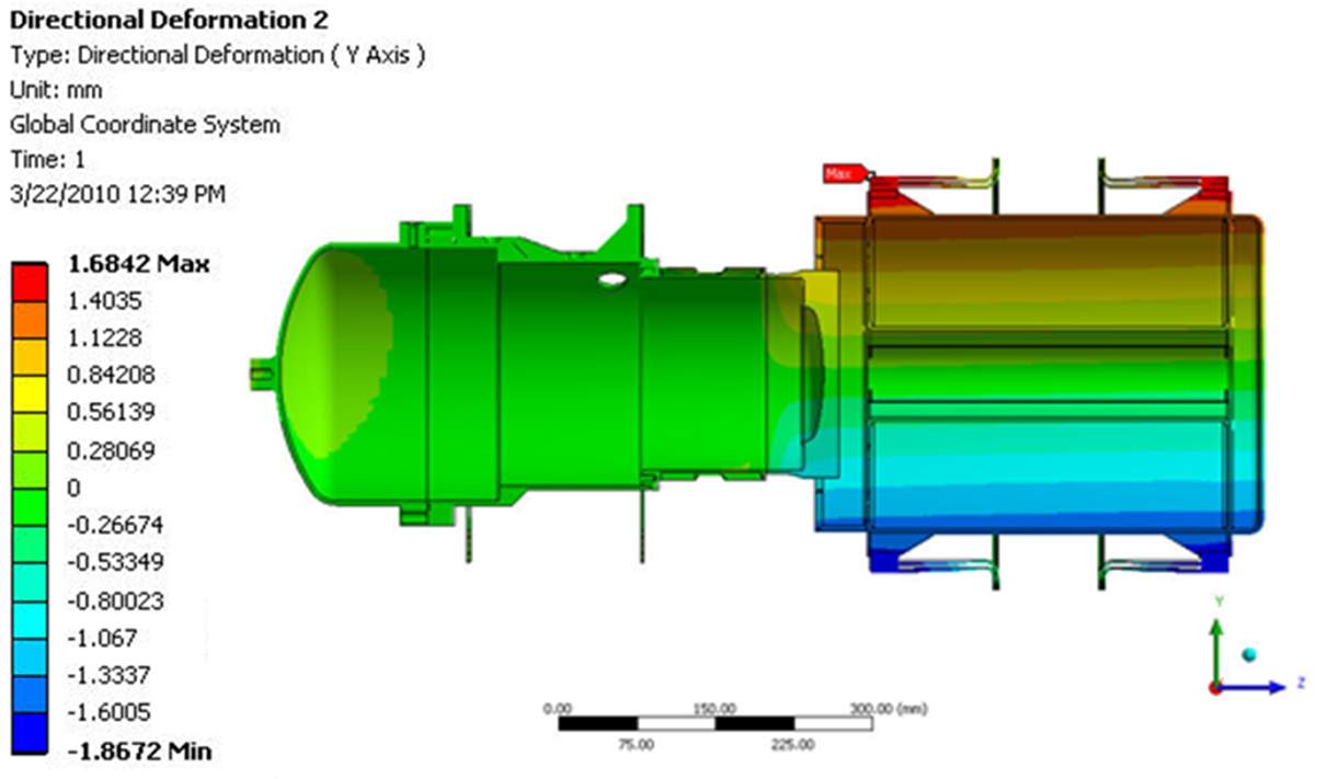
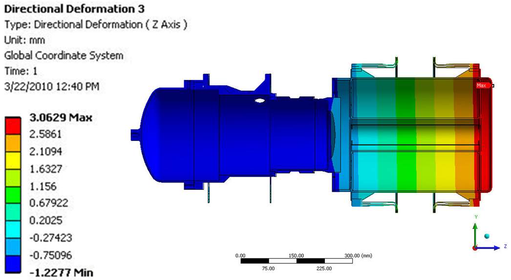
The vertical and axial deformation of the entire system is shown in Figure 9 and tabulated in Table 3. The model predicted a sag deflection of 0.10 mm for the TES container under the influence of gravity. This is well within the 0.5 mm design target. The net axial thermal expansion of the entire system was roughly 3.5 mm and these results are consistent with the results of the single flexure model. The TES vessel displaces 1.17 mm to the right and the engine center shifts 1.06 mm to the left as the total thermal expansion is taken by both the Stirling engine and the TES container flexures.
 |
 |
| Figure 9 – Vertical (top) and Axial (bottom) Deformation of the Stirling Engine-TES System. |
Table 3. Axial and Vertical Displacement of the Vessel (Axial: + is to the right; vertical: + is downwards)
| Axial shift
(mm) |
Sag under
gravity (mm) |
|
| vessel_left end | -0.44 | 0.09 |
| vessel_mid plane | 1.17 | 0.11 |
| vessel_right end | 3.01 | 0.12 |
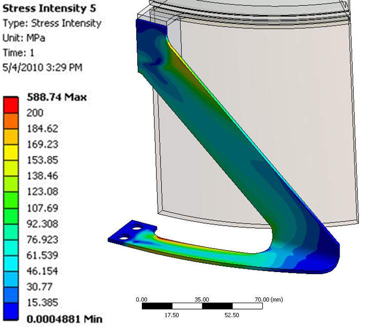
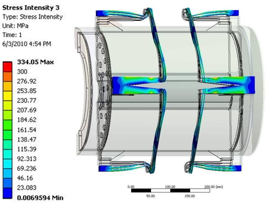
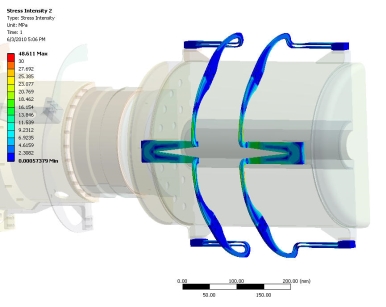
The stress at the welded joint between the heater head and TES container was predicted to only be 10 MPa. This indicates that using a welding method for the joint is safe and acceptable. The stress field in the TES and engine flexures is shown in Figure 10. It can be seen that the max membrane stress in the TES flexures is 80 MPa, well below the Sm value, and the max stress is 231 MPa and occurs near the junction of the flexure. This is still before the 3Sm value of 474 MPa, therefore the stress meets the design criteria.
 |
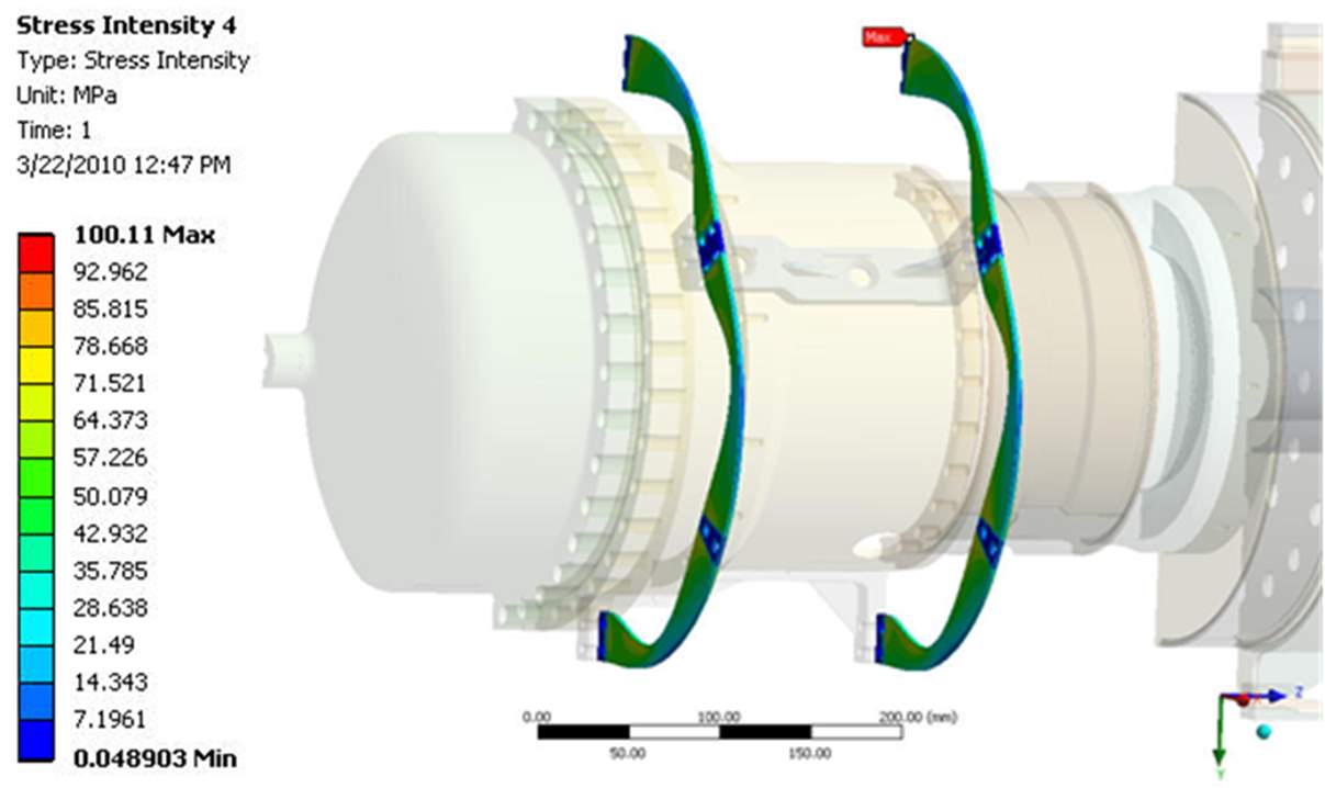 |
| Figure 10 – Stress fields within the TES (top) and engine (bottom) flexures |
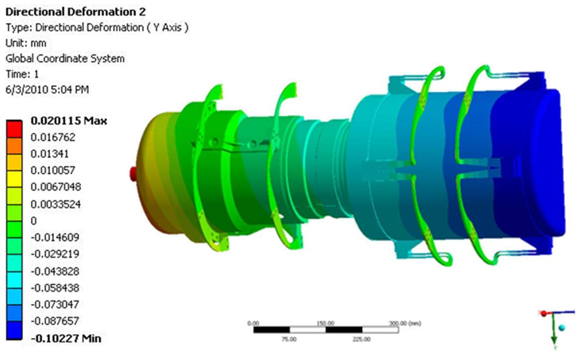
The system also underwent both high-cycle fatigue (N=1.5×10¹⁰, Sa = 135 MPa) and low-cycle fatigue (N=27000, Sa = 270 MPa). In order to calculate the low fatigue stresses, the stress field was calculated for the case in which initial temperature was set to room temperature and the other boundary conditions and mechanical loading was kept the same. The variation in the stress range was then calculated. The vertical axial deformation of the system along with the stress field of the TES flexures is presented in Figure 11. The maximum stress is only 48.5 MPa while the max displacement was 0.02 mm. The FEA results indicate that the max stress range for the low-cycle fatigue stress is 187.6 MPa. This value is lower than the 270 MPa Sa from the design criteria. This yields a margin of safety, MOS, of 0.439. The high cycle fatigue stress was obtained by calculating the variation in stress from two different cases, where a 0.34 mm axial displacement load was applied to the center of gravity of the Stirling engine. Note that the 0.34 mm is the typical case motion experienced by the engine during operation with a badly tuned balancer, hence this is a highly conservative case. The results showed that the high cycle stress range is very small with only a value of 55.2 MPa. This yields a MOS of 1.45. Therefore, the flexure design is safe for both the high and low cycle fatigue and the low cycle fatigue stress dominates the fatigue design. Additionally, note that the system analysis presented here is with the L-shaped TES flexure if the inverted 7 design was used it is likely that the displacements, stress, and fatigue stress would decrease as the overall thermal stress in this design is lower. Furthermore, this would lead to an increase in the MOS.
 |
 |
| Figure 11 – Vertical deformation of the Stirling engine-TES system (top) and stress within the TES flexures at room temperature (bottom) |
Experiments
The flexures along with the TES solar power system are first going to be tested at the laboratory scale where a fuel combustor replaces the solar energy from the solar dish. After the laboratory scale testing, the system and flexures will be tested in a full-scale PowerDish. The result of the experimental testing will be compared to the values predicted by the simulations. The lab scale test rig setup is shown in Figure 12. Fabrication of the salt vessel flexures and the vessel engine system is ongoing.
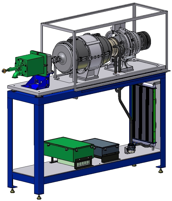 |
| Figure 12 – Laboratory scale experimental set up |
Conclusions
The design of a novel flexure for the support a high-temperature TES molten salt container was analyzed using FEA. The design challenges result from the larger degree of thermal expansion that results from the high-temperature experienced by the system, high thermally induced stresses, and the cost requirement. The TES flexures also experience both high- and low-cycle fatigue stresses and have a large thermal gradient. Furthermore, the flexures need to be axially compliant and laterally rigid. Due to the high temperatures, Inconel 625 was selected as the flexure material. The TES flexure underwent numerous design iterations and the stress within two designs was presented. In addition to a single flexure model, a system scale model was developed to identify the effects of gravity as well as the impact of the Stirling engine on the TE flexures. Both the L-shaped and inverted 7 flexure design met the stress, displacement, and fatigue requirements set forth in the design criteria based on the ASME boiler and pressure vessel code. The flexures will be fabricated and tested with the free-piston Stirling engine and the molten salt phase change TES vessel attached at both the laboratory scale and within a full-size PowerDish.
Acknowledgments
The authors would like to thank Brad Ring, the Technical Monitor, for financial and technical support.
References
[1] Mancini, T., Heller, P., Butler, B., Osborn, B., Schiel, W., Goldberg, V., Buck, R., Diver, R., Andraka, C., Moreno, J., Mancini, T., Heller, P., Butler, B., Osborn, B., Schiel, W., Goldberg, V., Buck, R., Diver, R., Andraka, C., and Moreno, J., 2003, “Dish-Stirling Systems: An Overview of Development and Status,” J. Sol. Energy Eng., 125(2), p. 135.
[2] Trieb, F., Langniß, O., and Klaiß, H., 1997, “Solar Electricity Generation – A Comparative View of Technologies, Costs and Environmental Impact,” Sol. Energy, 59(1–3), pp. 89–99.
[3] Stine, W. B., Diver, R. B., William B. Stine and Richard B. Diver, Stine, W. B., and Diver, R. B., 1994, A Compendium of Solar Dish/Stirling Technology.
[4] Santos-Martin, D., Alonso-Martinez, J., Eloy-Garcia, J., and Arnalte, S., 2012, “Solar Dish-Stirling System Optimisation with a Doubly Fed Induction Generator,” IET Renew. Power Gener., 6(4), pp. 276–288.
[5] Kongtragool, B., and Wongwises, S., 2003, “A Review of Solar-Powered Stirling Engines and Low Temperature Differential Stirling Engines,” Renew. Sustain. Energy Rev., 7(2), pp. 131–154.
[6] Thombare, D. G., and Verma, S. K., 2008, “Technological Development in the Stirling Cycle Engines,” Renew. Sustain. Energy Rev., 12(1), pp. 1–38.
[7] Schreiber, J. G., 2006, “Summary of Stirling Convertor Testing at NASA Glenn Research Center,” (December).
[8] Gil, A., Medrano, M., Martorell, I., Lázaro, A., Dolado, P., Zalba, B., and Cabeza, L. F., 2010, “State of the Art on High Temperature Thermal Energy Storage for Power Generation. Part 1—Concepts, Materials and Modellization,” Renew. Sustain. Energy Rev., 14(1), pp. 31–55.
[9] Kuravi, S., Trahan, J., Goswami, Y., Rahman, M. M., Stefanakos, E. K., Goswami, D. Y., Rahman, M. M., Stefanakos, E. K., Goswami, Y., Rahman, M. M., and Stefanakos, E. K., 2013, “Thermal Energy Storage Technologies and Systems for Concentrating Solar Power Plants,” Prog. Energy Combust. Sci., 39(4), pp. 285–319.
[10] Zhao, W., Zheng, Y., Sabol, J. C., Tuzla, K., Neti, S., Oztekin, A., and Chen, J. C., 2013, “High Temperature Calorimetry and Use of Magnesium Chloride for Thermal Energy Storage,” Renew. Energy, 50, pp. 988–993.
[11] Ushak, S., and Grageda, M., 2015, Using Molten Salts and Other Liquid Sensible Storage Media in Thermal Energy Storage (TES) Systems, Woodhead Publishing Limited.
[12] Gomez, J., Glatzmaier, G. C., Starace, A., Turchi, C., and Ortega, J., 2011, “High Temperature Phase Change Materials for Thermal Energy Storage Applications Preprint,” SolarPACES 2011, (August).
[13] Mohammadi Zahrani, E., and Alfantazi, A. M., 2012, “Corrosion Behavior of Alloy 625 in PbSO4-Pb3O4-PbCl2- ZnO-10 Wt Pct CdO Molten Salt Medium,” Metallurgical and Materials Transactions A: Physical Metallurgy and Materials Science, pp. 2857–2868.
[14] Sarvghad, M., Steinberg, T. A., and Will, G., 2017, “Corrosion of Steel Alloys in Eutectic NaCl+Na 2 CO 3 at 700 °C and Li 2 CO 3 + K 2 CO 3 + Na 2 CO 3 at 450 °C for Thermal Energy Storage,” Sol. Energy Mater. Sol. Cells, 170(March), pp. 48–59.
[15] Liu, S., Liu, Z., Wang, Y., and Tang, J., 2014, “A Comparative Study on the High Temperature Corrosion of TP347H Stainless Steel, C22 Alloy and Laser-Cladding C22 Coating in Molten Chloride Salts,” Corros. Sci., 83, pp. 396–408.
[16] Gomez-Vidal, J. C., and Tirawat, R., 2016, “Corrosion of Alloys in a Chloride Molten Salt (NaCl-LiCl) for Solar Thermal Technologies,” Sol. Energy Mater. Sol. Cells, 157, pp. 234–244.
[17] Sarvghad, M., Will, G., and Steinberg, T. A., 2017, “Corrosion of Inconel 601 in Molten Salts for Thermal Energy Storage,” Sol. Energy Mater. Sol. Cells, 172(July), pp. 220–229.
[18] Al-Otaibi, Z. S., and Jack, A. G., 2007, “Spiral Flexure Springs in Single Phase Linear-Resonant Motors,” Proc. Univ. Power Eng. Conf., pp. 184–187.
[19] Zhou, W. J., Wang, L. Y., Gan, Z. H., Wang, R. Z., Qiu, L. M., and Pfotenhauer, J. M., 2012, “The Performance Comparison of Oxford and Triangle Flexure Bearings,” AIP Conf. Proc., 1434(57), pp. 1149–1156.
[20] Rajesh, V. R., and Kuzhiveli, B. T., 2017, “Modelling and Failure Analysis of Flexure Springs for a Stirling Cryocooler,” J. Eng. Sci. Technol., 12(4), pp. 888–897.
[21] Malpani, Saurabh, Yogesh Yenarkar, Dr. Suhas Deshmukh, S P Tak, D. V. B., 2012, “Design OF Flexure Bearing For Linear Compressor By Optimization Procedure Using FEA,” Int. J. Eng. Sci. Technol., 4(5), pp. 1991–1999.
[22] Khot, M., and Gawali, B., 2015, “Finite Element Analysis and Optimization of Flexure Bearing for Linear Motor Compressor,” Physics Procedia, Elsevier B.V., pp. 379–385.
[23] Achanur, M., 2014, “Shape Factor Optimization and Parametric Analysis of Spiral Arm Flexure Bearing Through Finite Element Analysis Studies,” Int. J. Eng. Res. Technol., 3(4), pp. 585–588.
[24] Chen, N., Chen, X., Wu, Y. N., Yang, C. G., and Xu, L., 2006, “Spiral Profile Design and Parameter Analysis of Flexure Spring,” Cryogenics (Guildf)., 46(6), pp. 409–419.
[25] Yun, G., Abdullah, A. B. M., Binienda, W., and Krause, D. L., 2014, Test Methodology Development for Experimental Structural Assessment of ASC Planar Spring Material for Long-Term Durability.
[26] Gaunekar, A. S., Widdowson, G. P., Srikanth, N., and Guangneng, W., 2005, “Design and Development of a High Precision Lens Focusing Mechanism Using Flexure Bearings,” Precis. Eng., 29(1), pp. 81–85.
[27] Calvet, R. J., Liu, X., and Jain, A., 2011, “Planar Flexure System with High Pitch Stiffness.”
[28] Howell, L. L., Thomson, S., Briscoe, J. A., Parise, J. J., Lorenc, S., Larsen, J. B., Huffmire, C. R., Burnside, N., and Gomm, T. A., 2006, “Compliant, Ortho-Planar, Linear Motion Spring.”
[29] Lee, S. W., Yu, M. J., and Kim, I. S., 2016, “Design and Fabrication of a Superconducting Relative Gravimeter with a Planar Spring,” IEEE Sens. J., 16(9), pp. 2958–2963.
[30] Qi, P., Qiu, C., Liu, H., Dai, J. S., Seneviratne, L. D., and Althoefer, K., 2016, “A Novel Continuum Manipulator Design Using Serially Connected Double-Layer Planar Springs,” IEEE/ASME Trans. Mechatronics, 21(3), pp. 1281–1292.
[31] Sugandi, G., Mambu, G. A., Mulyadi, D., and Mulyana, E., 2017, “Fabrication and Characterization of Planar Spring Based on FR4-PCB for Electrodynamics Vibration Energy Harvesting Application,” IOP Conf. Ser. Mater. Sci. Eng., 214(1).
[32] 2010, “ASME Boiler and Pressure Vessel Code an International Code,” Am. Soc. Mech. Eng.
Cite This Work
To export a reference to this article please select a referencing stye below:
Related Services
View all


Related Content
All TagsContent relating to: "Maritime"
Maritime is something relating to the seas and oceans. The term is commonly used in nautical and seaborne trade matters. Not to be confused with “marine” which relates specifically to the seas, oceans and the life within them.
Related Articles

DMCA / Removal Request
If you are the original writer of this dissertation and no longer wish to have your work published on the UKDiss.com website then please: