Coal Bed Methane Reservoirs and their Development
Info: 11174 words (45 pages) Dissertation
Published: 16th Dec 2019
Tagged: Environmental Science
Topic: Introduction to Unconventional Reservoirs and Their Development (MD01)
Subtopic: Coal Bed Methane Reservoirs and Their Development (MD01-05)
Subject 1: Geologic Setting of Coal Bed Methane Reservoirs
Methane Sources and Storage Mechanisms in Coal
Subject 2: Reservoir Quality of Coal Seams
Coal Bed Methane Reservoir Characteristics
Measuring Coal Bed Methane Reservoir Quality
Subject 3: Drilling and Completion of Coal Bed Methane Wells
Drilling Coal Bed Methane Wells
Coal Bed Methane Well Completion and Stimulation
Artificial Lift for Coal Bed Methane Wells
Subject 4: Reservoir Performance and Reserves Estimation of Coal Bed Reservoirs
Subject 5: Development of Coal Bed Methane Reservoirs
Coal Bed Methane Development Case History: San Juan Basin, USA
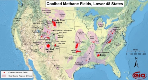
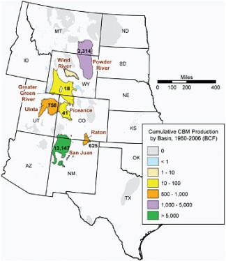
Coal bed methane (CBM), which is also referred to as coal seam gas (CSG) in some parts of the world is methane that is generated and trapped in a coal seam. In the United States, more than 32 trillion cubic feet (TCF) of natural gas has been produced from CBM through 2013 (US EIA, 2015). CBM is produced from basins across the United States and in a number of countries around the world. Figure 1 from the United States Energy Information Administration (US EIA), visually illustrates the location of CBM basins and production in the US.
 |
|
CBM has been a relatively small but important contributor to natural gas production in the United States for decades. CBM continues to be an important part of natural gas exploration and production in the United States and is still in a growth stage in many other countries around the world. While there may be large volumes of gas in place, the volumes that are technically recoverable can be considerably smaller and the economically recoverable volumes yet smaller. The countries with the most potential for CBM development based upon the volume of resource are the United States, Russia, China, Australia and Canada. The US and Australia both produce significant amounts of methane from coal.
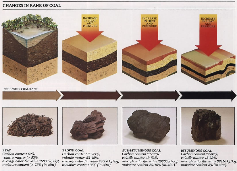
Most depositional models for coal-bearing strata suggest that coal originated as peat formed in swamps on low-lying ground in deltas, alluvial plains and coastal areas (McCabe, 1985). Over time, the peat swamp became buried due to the influx of non-carbonaceous sediments. The accumulation of this sedimentary material over time compressed the peat, forcing the removal of water. Finally, the compacted peat is transformed into coal through a process called coalification which involves physical, chemical, and biological changes.
The coalification process continues as the buried carbonaceous material is exposed to continued heat and pressure and passes through the stages from peat to lignite, sub-bituminous coal, bituminous coal and in some cases to anthracite coal. The degree of alteration that occurs as a coal metamorphoses from peat to anthracite is referred to as the “rank” of the coal. Low-rank coals (lignite and sub-bituminous coals) have a lower energy content because they have a low carbon content. Figure 2 visually demonstrates this process.
 |
|
The primary organic components of coal are macerals, leftover remnants of the original vegetation that composed the original peat. Macerals are microscopically recognizable organic constituents that can be grouped according to their original source material (Table 1).
|
|
| Vitrinite (also called Huminite in low rank coals) | Woody tissue, roots, bark |
| Liptinite | Leaf cuticles, spores, pollen |
| Inertinite | Plant material that has been burned, degraded or otherwise reduced to charcoal |
Maceral content varies from coal to coal. Each maceral has a differing percentage of hydrogen and carbon which can lead to differences in the amount of methane that can be generated from a given coal. For example, a high percentage of inertinite will lower the amount of methane that can be generated from the coal on a unit basis.
Maceral maturity can be estimated by measuring vitrinite reflectance. This value helps to identify the carbon, hydrogen and nitrogen composition of the coal. Typical values range from 0.5% to 1.5% for coals considered for CBM production.
Methane Sources and Storage Mechanisms in Coal
Following deposition of the peat and the initiation of the coalification process, methane begins to form. Methane gas is primarily generated from the action of anaerobic microbes which break down various hydrogen and carbon components in the coal over time. Methane generation may occur rapidly when conditions are optimal for microbial life or it may occur slowly over long periods of time.
The process by which methane is generated by microbes is called methanogenesis and the gas which is created by that process is referred to as biogenic gas. Biogenic gas is generated through a multistep process involving several different groups of microbes. The microbes extract microscopic compounds from the coal and eventually excrete methane gas as a waste product of their metabolism.
These microbes can also metabolize other hydrocarbon gases such as ethane, propane or butane. If these hydrocarbon compounds are generated during the methanogenesis process, they are typically consumed by the microbes at a later time, thus biogenic methane tends to be very “dry” or pure methane without the inclusion of other hydrocarbon gases. The methanogenesis process does produce some carbon dioxide and thus carbon dioxide is often produced from CBM wells, typically at a low percentage (2-5%).
Some coals also contain thermogenic methane which is methane that is created by the conventional hydrocarbon generation process involving heat and pressure but not through microbial activity. Some coals follow a process of diagenesis which does not allow biogenic methane to be generated, or at least severely limits the amount which can be generated. If these coals are then buried at a significant depth and experience a history of higher heat flow, thermogenic methane may be generated from the hydrogen and carbon within the coal. It is also possible for thermogenic methane to migrate from a deeper zone into a coal seam.
Geologists have learned to distinguish between biogenic and thermogenic methane within a coal seam by analyzing the isotopic composition of the carbon within the methane. By analyzing the composition, the ratio of carbon isotopes within the methane can be determined, specifically the ratio of 13C to 12C. Microbes that create biogenic methane have a preference for compounds containing 12C. Therefore, the methane that is generated from a biogenic process has a higher percentage of 12C than the amount generally found in nature.
Almost every coal, from lignite to anthracite, contains some volume of methane. However, it is primarily stored in a different way than in conventional reservoirs. In a conventional reservoir, hydrocarbons are stored in the pore spaces of the formation. In the case of CBM most of the methane molecules are adsorbed onto the surfaces of organic material in the coal. Remember that adsorption is a completely different process than absorption. Because the spelling is very similar, it is easy to confuse the words. Absorption means incorporation or assimilation, such as when a solid absorbs a liquid or a liquid absorbs a gas. Adsorption means the adhesion of individual molecules to the surface of a solid, either due to physical or chemical forces.
When generated during the coalification process, methane molecules will adsorb to the microscopic internal structure within the coal seam. Methane will continue to adsorb until an equilibrium is reached based on the surface area available for adsorption and the pressure within the seam. When the volume of methane reaches the maximum amount the conditions of the coal can support, the coal is considered to be “saturated.” A relatively small percentage of methane will remain as free gas or dissolved in water within the macropores and fractures (cleats) of the coal seam.
A saturated condition means that the methane will be produced very quickly upon initiation of a producing well. The fractures may be completely saturated with water, which must be pumped out of the coal seam to permit the reservoir pressure to drop to a point where methane molecules adhering to the surfaces in the coal matrix begin to desorb from the matrix and flow along the pores and fractures to a wellbore.
Subject 2: Reservoir Quality of Coal Seams
Just like conventional petroleum reservoirs, understanding the factors that affect CBM reservoir quality is critical in CBM exploration. The greater our understanding, the greater our ability to propose a development plan that will allow for economic production.
There are a number of coal characteristics that, in combination with other factors, will determine how a CBM resource can be developed and produced most effectively. These include: coal rank, gas content, thickness, and depth.
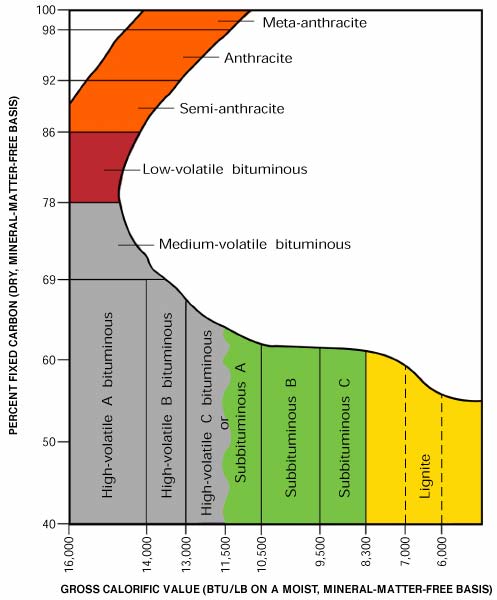
The thermal maturity or rank of a coal seam is one of the most common methods used to describe coals. Rank is described with several terms beginning with lignite and continuing to anthracite. Figure 1 shows how the carbon content and energy content change with coal rank. These parameters are used to help categorize coal seams. The fixed carbon content of the coal is the carbon found in the material which is left after volatile materials are driven off. This differs from the ultimate carbon content of the coal because some carbon is lost in hydrocarbons with the volatiles.
 |
|
Following coalification, the coal is first referred to as lignite (also called brown coal in some parts of the world). Lignite is the lowest rank of coal and has the lowest energy content per ton in part because the moisture content is often greater than 50%. Few CBM development projects have been implemented in lignite deposits with the exception of some of the shallow coals in the Powder River Basin of Wyoming.
With additional heat and pressure, lignite is transformed into sub-bituminous coal. Many CBM fields are successfully developed in sub-bituminous coals. With additional heat and pressure, the coal becomes bituminous. Some CBM fields are developed in bituminous coals, most notably the San Juan Basin in New Mexico.
Finally, a coal becomes anthracite. At this point of coalification, the permeability of the coal has been significantly reduced and most of the volatile matter including methane, has been driven off by the increased heat and pressure. Since very little methane remains in anthracite, there are almost no CBM projects developed in anthracite seams.
The most common coal analyses performed to provide information about the coal rank are Proximate and Ultimate Analyses. A Proximate Analysis is a relatively inexpensive method for providing data on: moisture content, volatile matter, fixed carbon, ash content, and sulfur content. The Ultimate Analysis is a more thorough analysis which provides additional information about the energy content and specific percentages of elements found within the coal, especially carbon, hydrogen, oxygen and nitrogen. Both of these analyses, while of some use to CBM developers when done on core samples, are more commonly used to characterize near-surface coal seams that will be mined and burned for energy.
After identifying the rank of the coal, the gas content, the volume of methane per unit mass of coal, is the next most important component. Gas contents are expressed in units of standard cubic feet of methane per short ton of coal (scf/ton). Gas content values can range from 0 to greater than 1000 scf/ton, but most coals are in the range of 50-500 scf/ton. Gas content is measured through desorption analysis, which is a process of measuring the gas volume recovered from a coal sample as the gas desorbs.
Gas content increases as rank increases and also increases with depth as the increased pressure allows a greater volume of gas to be stored within the coal. Some lignites have very little to no gas content if they are very young or have never experienced enough heat flow to generate thermogenic gas. Additionally, a lack of gas content may indicate that methane which may have been generated within the coal was able to escape to other zones due to the lack of an impermeable seal above the coal seam.
Coal seams can be found with a thickness of less than an inch and up to 300 feet in a single seam. In some areas, notably the Latrobe Valley of Victoria, Australia, multiple seams combine to create a thickness of 750 feet of almost continuous coal. For any single CBM well, the larger the total thickness of coal penetrated, the greater the volume of methane in place for that well.
CBM development projects typically target single coal seams that are greater than 10 feet in thickness or a combination of seams exceeding that thickness. A single seam only a few feet thick is unlikely to be economic unless it is extremely shallow or has unusually high gas content. For practical purposes, when using a geophysical well log to identify coal seams, a seam less than 2 feet thick can be difficult to correctly identify without a correlation to core.
In addition to thickness, the continuity of the coal between well locations is important to verify. If wells are separated into different blocks due to faults, non-deposition or post-depositional erosion of the coal, then the development strategy may need to accommodate this situation.
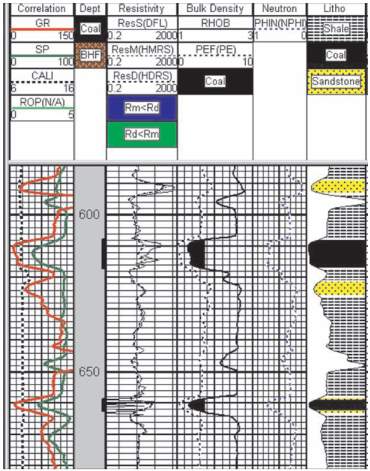
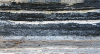
Most coals can be positively identified in wells using a gamma ray (GR) log in combination with a bulk density log. Bulk density values for coals are typically equal to or less than 1.75 g/cc and may be as low as 1.2 g/cc for lignites. Washouts in a wellbore can influence the bulk density values, so integrating a GR log helps to positively identify a coal. GR values are generally lower in coal seams than in other formations; often lower than 45 API units. Resistivity logs can be useful depending on the salinity of the water in the coal seam. Coals also show a high response on sonic logs. Figure 2 illustrates some of these log responses in coal. Of course, cuttings and full core can also help to identify the location of coal seams.
 |
|
Coal seams have been found in surface outcrops and at depths greater than 10,000 feet. Generally, CBM production occurs from coals in the depth range of 500 to 3000 feet. To produce methane from a coal, the methane must be trapped in a coal seam by an overlying impermeable layer. Coals that are less than a few hundred feet in depth may not have a sufficient seal above. Likewise, they may be in close proximity to an outcrop which could allow the methane to escape prior to production.
While there is no specific lower depth limit to CBM production, the coal permeability generally decreases with depth. Coals located at a depth of 6000 feet or greater generally have a permeability that is too low for successful CBM production without hydraulic fracturing or other completion techniques. The additional completion expense, combined with the increased cost of drilling deeper, generally makes coals at this depth or beyond uneconomic. An exception would be if the coal is in an area where post depositional tectonic forces have created an area of increased permeability unrelated to the primary permeability system native to the coal itself.
Coal Bed Methane Reservoir Characteristics
When compared with the elements of traditional petroleum exploration, the coal seam itself serves as the source, the reservoir and the trap. The coal is the source because it contains the organic items that provide the hydrogen and carbon from which the methane is produced. It is the reservoir because the methane is generated inside the coal seam both during and after deposition and there is no need for migration of the methane. Finally, the coal seam provides a stratigraphic trap for the gas, although there must still be an impermeable seal overlying the coal to prevent the methane from migrating out of the coal. The structural position of the coal is less important in CBM than in other plays. The greatest impact of structure is on water production.
Porosity and permeability are closely related in coal due to the unique nature of the cleating system within coal seams. Cleats are natural fractures that develop in a coal during the coalification process. They are in part related to water removal from the coal over time and also related to regional stresses within the formation that occur after deposition. For example, if a basin is subsiding after deposition of the coal, the tectonic stress caused by the subsidence may influence the orientation of the cleats. Cleat spacing changes as coal rank changes.
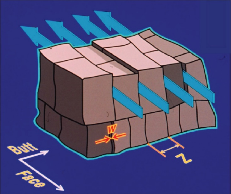
The primary and most prevalent cleats are the face cleats. These extend parallel to each other throughout the coal. Perpendicular to the face cleats are another sets of cleats called the butt cleats. As shown in Figure 3, the less prevalent butt cleats connect between face cleats but are not continuous across the face cleats. The result of this situation is that a CBM well will typically draw water and then gas primarily from the face cleats connected to the wellbore, leading to an elliptical drainage pattern around the well whose long axis is parallel to the face cleats.
 |
|
Understanding the unique cleating system in coal is important because the cleats provide the primary porosity and permeability of the coal. The coal pieces located between the cleats are referred to as the coal matrix. While the porosity inside the matrix can be high due to the nature of the organic macerals and their large surface area, the permeability of the matrix is often very low. When permeability is tested and reported in a CBM well, the result is actually an average between the cleat permeability and matrix permeability. Typical CBM wells have a permeability between 1 and 100 millidarcies (md). Some wells, especially in the Powder River Basin of Wyoming, have permeability measurements as high as 1000 md.
Another important factor which affects the reservoir quality is the water within the coal seam. The geochemistry of the water produced from the coal seam will have a large impact on disposal options. Fresh water can often be disposed of at the surface into surface streams or ponds, while water with a higher salinity may need to be treated or disposed of in a deeper formation.
Measuring Coal Bed Methane Reservoir Quality
Reservoir quality is determined by the volume of gas in place and the ability of the coal seam to produce that gas at economic rates. We will look at each of the elements of those two features.
Gas Content – Perhaps the most important measure of CBM reservoir quality is gas content, the volume of gas per unit mass of coal, usually reported in units of standard cubic feet per ton (scf/ton). (Note: The ‘ton’ in this unit is a short ton equal to 2000 pounds. Coal units are sometimes expressed in metric tonnes which are equal to 2204.6 pounds, so take care to be certain of the units.) Since the coal is under hydrostatic pressure while in the seam, once it is brought to the surface at atmospheric pressure, the methane begins to desorb from the coal just as it would underground during production when the water is removed thus lowering the pressure in the seam.
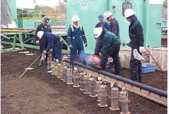
The common method for measuring gas content is a canister desorption test conducted by placing a freshly cut conventional core sample in a sealed container at reservoir temperature and measuring the amount of gas released as a function of time (Figure 4). Typically the core is cut into 1 foot sections for the canisters. Further, the desorbed gas volumes must be corrected for any ambient pressure variations during the measurement period. In addition to the desorbed gas volume measured, the volume of gas that desorbs from the sample during the core recovery process before the core sample can be sealed in the desorption canister (“lost gas”) must be estimated. Usually the greatest source of error in a total gas content estimate made using a canister desorption test is the lost gas number. Pressure coring is an expensive and rarely used option for eliminating lost gas.
  |
|
There must also be an estimate of “residual gas” that remains sorbed on the sample at the conclusion of the canister desorption test. The residual gas volume is estimated by crushing the entire core sample and measuring the gas volume released at the reservoir temperature.
The total gas volume is the sum of the lost gas, desorbed gas, and residual gas volumes (reported at standard temperature and pressure) and reflects the total estimated gas volume in the coal at initial reservoir pressure and temperature. This volume is divided by the measured mass of the original sample, to arrive at total gas content in units of scf/ton
The manner in which the sample mass is determined is important. For example, if one uses the actual sample weight, regardless of the moisture content or the presence of non-coal material in the canister sample (raw basis), or if one uses an “air-dry” basis where the entire sample has been allowed to air dry to a constant equilibrium weight in a laboratory climate and further corrected for any residual moisture and non-coal content based on the proximate or ultimate analysis described earlier.
Gas content will not be uniform throughout the coal seam because coal composition is not uniform throughout deposit. To obtain a statistically reliable estimate of in-situ gas content, the gas content from multiple samples having a broad range of compositional values must be measured in a consistent manner. This is typically done through a field-wide coring and testing program.
The gas produced from coal often contains significant amounts of carbon dioxide, nitrogen, and even some molecular weight hydrocarbons heavier than methane. It is important to determine the composition of the gas collected from the desorption tests in order to determine the total methane content and thus the true sales value of the gas and the need for any special treatment to remove contaminants like carbon dioxide.
Area – Estimating the volume of gas-in-place also requires thickness, area and formation density measurements in addition to the gas content per unit mass. Together these factors determine the richness or quality of the CBM reservoir.
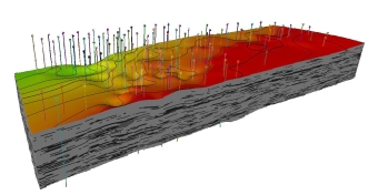
The reservoir area is usually estimated based on mapped extent of the coal if the seam can be assumed to be laterally continuous. Structural and stratigraphic variations across the coal seam must be characterized, initially through exploratory wells and then through three dimensional modeling based on development well data (Figure 5). Logs can provide clues about the continuity of individual intervals within the coal seam(s) drilled. Three dimensional seismic data can be also used to determine coalbed methane reservoir area.
 |
|
Thickness – Coal thickness is determined with wireline logs, most typically openhole density logs. The gross thickness is computed by summing the thicknesses of intervals having densities below a certain cut-off value (remember, coal is less dense than the non-coal minerals and sediments with which it is interbedded) (Figure 6). Determining net thickness requires evaluating how much of the gross coal thickness actually contributes to production. Resistivity logs, individual well tests, production logs run on producing wells, or flow tests run on isolated zones within a well can be used to estimate the net thickness.
 |
|
Density – The in-situ coal density is typically estimated from open-hole density log data or calculated based on the individual densities and fractions of the ash, moisture, and coal components determined from core sample analyses. Typical values are 1.32 to 1.36 g/cm3 for the average in-situ density, although this can vary.
So, the best quality reservoirs are ones with the highest volumes of gas in place: thick, widely distributed, high gas content (gassy) coal seams with little extraneous sediment interbedded with the coal and low amounts of carbon dioxide or other contaminates in the gas.
The final element of reservoir quality for CBM reservoirs relates to permeability and the ability of the coal seam to flow water and natural gas.
Permeability – As mentioned earlier, the flow of natural gas and water to the wellbore in CBM reservoirs relies on the natural fracture system (cleats). Because coals have a primary and secondary cleat system (face and butt cleats, respectively), coals experience directional permeability.
Accurate estimation of well deliverability requires good estimates of the cleat system flow properties. Absolute permeability and relative permeability are two of the most important natural fracture system flow properties that affect gas and water production rates.
Permeability measurements on core samples are not representative of the reservoir. This is because fractures may be more widely spaced than a core’s diameter and also because of the difficulty in obtaining competent core samples when the fractures are very closely spaced. Pressure transient testing is the only reliable way to accurately estimate overall in-situ natural fracture system permeability.
The unique characteristics of CBM reservoirs must be considered in the interpretation of CBM well test results; for example: a dual porosity system, two-phase flow of water and natural gas in the fractures, the tendency for permeability to be more dependent on stress in coal, and the prevalence of multiple intervals contributing to flow with many layered formations.
It is possible to estimate cleat system permeability from test data measured during two phase flow, but the results are dependent on the relative permeability relationship, which generally must be assumed. A single phase flow test is easier to interpret. Typically, in an under-saturated CBM reservoir the initial reservoir pressure is above the critical desorption pressure and the natural cleat system is saturated with water. If an injection/falloff test (water injection) is conducted at this point, the pressure in the natural fracture system remains above than critical desorption pressure and single-phase flow conditions will prevail during the test. Also in this case, the reservoir behaves as a single porosity system since the coal matrix is not affected during the test. This allows the use of a single porosity model to interpret the test results.
Well testing in a CBM reservoir is also used to obtain estimates of the natural fracture system pressure and skin factor, and can also be conducted after hydraulic fracturing to obtain estimates of the induced fracture properties. Well test data is combined with wireline log data, core analysis results, and fluid property measurements to predict future production rates under a variety of operating conditions.
Relative permeability is a key parameter in determining the deliverability of CBM reservoirs but in situ measurements of relative permeability in coal are rare and laboratory measurements on core samples are not considered to be representative of in situ reservoir relative permeability. The small conventional core plugs used to measured relative permeability in the laboratory do not adequately reflect the presence of natural fractures. Modeling through history matching of pressure and production data is considered to be the best method for obtaining realistic relative permeability values in CBM reservoirs.
Subject 3: Drilling and Completion of Coal Bed Methane Wells
Drilling Coal Bed Methane Wells
The drilling program for a CBM well is generally a less complex process than that for other types of unconventional reservoirs for several reasons:
- CBM reservoirs are generally shallow (~500 to 3000 feet deep, although the deepest CBM reservoirs in the US are ~7000 ft) compared to other unconventional reservoirs like shales and tight gas sands
- CBM reservoirs are generally under normal hydrostatic pressure or under-pressured rather than over-pressured (although some are over-pressured, e.g., portions of the Fruitland coal in the San Juan Basin of New Mexico, USA) and thus do not require specialized drilling fluids, high pressure equipment or more time-intensive drilling procedures
- Most shallow CBM wells can be drilled with a conventional drilling rig such as those used for drilling the top hole portions of deeper, horizontal shale wells, which reduces mobilization time and costs. In some areas (e.g., the Powder River Basin of Wyoming, USA) modified water well drilling rigs may be employed.
- Most CBM wells are vertical wells and do not have a horizontal lateral. However, some operators are drilling horizontal wells in coal seams (e.g., more than 200 horizontal CBM wells have been drilled in the Hartshorne Coal in the Arkoma Basin in southeastern Oklahoma, with an average horizontal length of ~ 2000 to 2500 feet.)
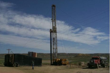
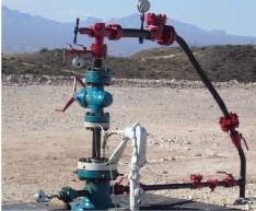
In some cases, a conventional drilling rig will be used to drill the well to the top of the target coal seam and at which point casing will be run and cemented and the rig then moved to the next well. A completion rig will be used to drill through the coal seam(s) and complete the well. In some areas, a well pad may not even be required if the existing landscape is flat and the location easily accessible by a truck-mounted rig (Figure 1).
 |
|
Rig and drilling fluid selection are guided by the completion method (discussed below). For some completions (e.g., dynamic-cavity) the rig will need to be equipped with a power swivel for rotating, reciprocating, and circulating during cleanouts. This type of completion will also require air compressors, blowout preventers, a rotating head, and a specially designed flow manifold for production testing.
When drilling a CBM well, it is particularly important to drill in such a way as to minimize permeability damaging effects on the coal seam. Water-sensitive shales near or interbedded with the coal seams may require the use of gas or mist rather than water based muds to minimize swelling and sloughing. Drilling slightly underbalanced can help to minimize coal formation damage if drilling mud is used. Air drilling can increase the rate of penetration and reduce drilling time and cost.
Surface casing is generally required by all regulatory agencies and the depth at which it is to be set is often prescribed by the agency. If not, the surface casing is set to a depth greater than the base of the deepest known freshwater zone in the area. Once the cement around the surface casing is set, drilling continues until the target coal seam is reached.
Drilling into the coal seam can lead to lost circulation of drilling fluids, especially if the natural permeability of the seam is high. As a result, many coals are completed as an “open hole” completion. This means that within the coal seam there is no casing set, but rather the seam is left open to the wellbore. This is especially true in areas where only a single seam is targeted. In the case of multiple seams at different depths within the same well, generally all seams except the deepest one will be behind casing, requiring perforation to access the seam.
A typical method for an open hole completion is to drill only slightly into the coal seam itself; perhaps 3-5 feet. Then the production casing is run and cemented in place. Otherwise, the cement tends to invade the coal seam itself which significantly reduces near wellbore permeability.
After the cement around the production casing is set, drilling continues until the base of the coal seam is reached. If logging is planned, a rathole depth may be drilled below the base of the coal seam to allow space for logging to begin below the actual seam. Likewise, if a submersible pump is expected to be used to de-water the coal, added depth may be required to allow space for coal debris to fall into the wellbore to a point below the pump level.
If a water-filled zone which has higher permeability than the coal is located directly below the coal seam, or within the proposed rathole depth, then the total depth of the well should be modified to avoid that zone. Because water removal is required from the coal seam to accomplish gas production, connecting the wellbore to a water-filled zone with higher permeability than the coal will allow preferential water production from the other zone, rather than the coal seam, reducing the efficiency of gas production.
Representative gas content values are dependent on recovery of a high percentage of the cored coal interval. Unfortunately, recoveries in higher-quality coals tend to be lower because these coals are highly cleated and friable, causing them to break up during the coring process. Also, operators may wait to core until they see a gas kick on the mud log or a sudden increase in rate of penetration indicating coal is being drilled. This means that the top few feet of the coal seam will be lost and, if the coal seam is very thin, perhaps missed entirely.
Coal Bed Methane Well Completion and Stimulation
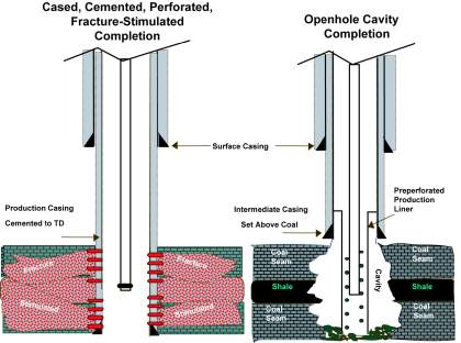
Once drilling operations are complete, the well completion operations can begin. A number of different types of CBM well completion methods have been developed to connect the wellbore and the cleat system within the coal seam. The most common approach is to run, set and perforate casing, and then hydraulically fracture the coal seam or seams. Fracturing jobs in lower-permeability coals require long, narrow, well-propped fractures not unlike those designed for shales or tight sands. In higher permeability coals, short, wide, unpropped fractures are suitable. If the permeability is high enough and the coal formation face is relatively undamaged by the drilling process, a simple openhole completion may be optimum. In a few areas, dynamic-cavity or cavitation completions are used (Figure 2).
 |
|
Cased and Perforated Completions – Cased and perforated CBM wells have advantages over open-hole completions: interbedded non-coal lithologies can be sealed off behind pipe (e.g., permeable zones that contribute water) and perforating coal seams individually permits customized fracture treatments optimized for a particular coal seam or group of seams. As with other types of unconventional reservoirs, hydraulic fracture stages in a cased well can be isolated with a variety of plugging mechanisms. Limited-entry fracture stimulations may be appropriate if there are multiple coal seams distributed over a long interval. In cases where there are multiple thin coal layers, a coiled-tubing unit can be used to treat each seam in succession.
CBM hydraulic fracture stimulation treatments typically are water based and can be characterized as: slickwater, water based gel, energized foam, or proppantless fracs.
Slickwater fracs (water and a friction reducer) are considered to be less damaging to the coal formation than gel treatments and are also generally less expensive on a per volume basis. CBM well slickwater fracturing treatments are typically are pumped at high rates e.g., 50 to 80 bbl/min) to compensate for the poor proppant-carrying capacity of the fluid.
Typical CBM well slickwater treatments use 12/20- to 20/40-mesh sand with proppant loadings of 2,000 to 3,000 lbm/ft of net coal, ramping up from 1 lbm/gal to 4 to 6 lbm/gal at the end of a typical treatment. A disadvantage of a slickwater fracturing treatment is a tendency for premature screenout, which creates short fracture half-lengths (SPE, 2016).
Gelled water-based stimulation fluids use polymers (linear or cross-linked gels) to increase water viscosity and thus proppant transport capacity, allowing larger jobs to be pumped (loadings of 5,000 to 10,000 lbm/ft of net coal). The disadvantage to a gel-based fluid is the potential for coal formation damage from gel residue.
Foam treatments incorporate nitrogen or carbon dioxide within a water-plus-additive-based fluid. Foam stimulations are often used in low permeability or low pressure coal reservoirs. These treatments permit rapid flowback of the fracturing fluid in low-pressure coals.
Proppantless stimulations generally use plain water and no proppant. These stimulations can be effective in locations such as the Powder River basin of Wyoming, where the objective is to simply connect the wellbore with the high-permeability cleat system. However, in lower-permeability coals such as the Black Warrior basin of Alabama, proppantless stimulations are less effective than sand/water stimulations by a ratio of 2:1 (SPE, 2016).
Open Hole Completions – For wells which are completed open hole, one completion strategy is to use a tool called an under-reamer, to increase the diameter of the wellbore within the coal seam. This tool has retractable elements which can be extended and rotated within the coal seam that will gradually increase the diameter of the wellbore. Performing this operation increases the surface area from which gas molecules can access the wellbore via the cleat system. In some cases the noncoal zones above and below the coal seam are also under-reamed to relieve stresses that could cause the coals to fail and slough off into the wellbore.
The dynamic cavity completion process involves injecting water, air and sometimes foam into the coal seam for a short time period, followed by a quick release of the built up pressure. The result is that the injected fluids, as well as dislodged pieces of coal, flow to the surface where they are directed through the wellhead and a flowline to a pit. The process is repeated multiple times, often for several days or weeks depending on the results of each cycle, until cavity diameters of up to 8 feet (as measured using sonar) are achieved. This process radically increases the surface area of the coal seam around the wellbore allowing greater and faster desorption of the coal. Cavitation is possible due to the soft and friable nature of coal as compared to other lithologies.
Other types of cavitation can also occur. For example, drilling cavitation is performed by drilling through the coal seam in an underbalanced state. The resulting pressure drop across the formation face causes the coal to break out along any near-wellbore cleat planes. High circulation rates (generally with air, gas, or mist to achieve underbalanced conditions) must be used to lift the coal debris from the hole effectively.
Natural cavitation begins with the drilling of a coal seam using air, gas, or a mixture of these. The drill string is then lifted out of the coal seam interval and the well is shut in. The pressure builds naturally until the well is abruptly opened at the surface. This release causes a sudden depressurization of the well accompanied by a surge of water, gas, and coal debris, which are produced up the well and through a flowline to the flare pit. The drillstring is then rotated to the bottom of the hole, while reciprocating and circulating through the coal interval. The cleaned out wellbore is checked for fill level and the operation is repeated until a sufficient sized cavity is achieved. Because large cavities are sometimes created, a substantial amount of the larger coal pieces may not be circulated out of the wellbore. It is important to drill up and clean this fill so that the well’s maximum production potential can be achieved.
Jetting cavitation uses hydraulic pressure to direct a jet of gas and water directly against the coal face. This process may be performed as a remedial technique in CBM wells where earlier cavitation methods have failed.
When the cavitation process is completed and the well is ready for production, it should be opened slowly over a period of several hours to limit the surging of water and gas into the wellbore, minimizing the movement of coal fines and the breaking off of coal chunks into the wellbore.
Artificial Lift for Coal Bed Methane Wells
Coal bed methane production is dependent on the reservoir pressure being reduced to permit methane to desorb from the coal. This requires the water filling the cleat system to be removed, so the first step in producing CBM wells is typically to pump out the water.
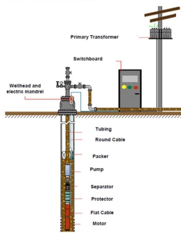
There are several different pump types that are typically used in CBM production and each has advantages and disadvantages. A typical option is an electrical submersible pump (ESP). An electrically powered centrifugal pump is placed at the bottom end of a tubing string the pump located as low as low in the coal seam productive interval as practical. The pump is powered by an electrical cable run along the tubing string (Figure 3). This deep location below the perforations will enable the removal of the greatest volume of water from the formation.
  |
|
A submersible pump is a good option unless the coal seam produces a large amount of coal “fines,” tiny mobile particles of coal which flow in the cleat system and can be produced along with the water. They often clog a submersible pump causing it to fail.
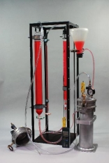
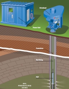
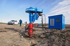
A better option for wells that produce fines or sediment along with the water is a progressive cavity (PC) pump (Figure 4). A PC pump is operated by a motor at the surface which turns a rod string connected to the pump mechanism at the bottom of the well. A special spiral rod inside a fitted sleeve within the pump opposite the coal zone provides the positive displacement of the liquid up the tubing string within which the rod string is suspended. A PC pump is much more effective at handling coal fines and other solids production than a submersible pump.
  |
|
In some cases, conventional rod pumps operated by surface pump jacks are also used to de-water the coal zone. In all of these cases, a source of electricity is required at the well location.
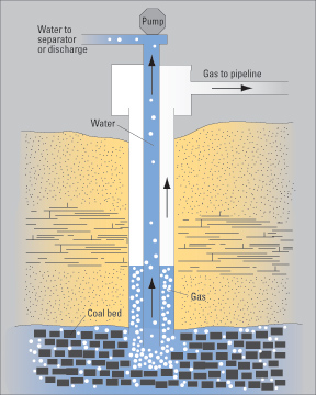
Regardless of the pump type used, CBM wells are generally configured such that any water is produced to the surface through the tubing. As the water stands inside the casing prior to moving up the tubing to the surface, the gas molecules which were carried to the wellbore in the water can separate due to the reduction in pressure and are then generally produced from the wellhead via a pipe connection to the casing itself. Figure 5 illustrates this configuration.
 |
|
Subject 4: Reservoir Performance and Reserves Estimation of Coal Bed Reservoirs
Once production has been initiated, routine monitoring should be put in place to understand if the reservoir is performing at optimal conditions. Gas production, water production, and reservoir pressures each provide important information about the reservoir over time.
One of the most important concepts in production, especially in a newly developed CBM area, is to maintain steady consistent production over time. When wells are shut in for an extended period of time (weeks or months), coal seam water from outside the well pattern may recharge the coal formation near the wellbore. When this situation occurs, the desorption benefit gained from lowering the pressure by de-watering is lost. A well which was producing primarily gas may return to only water for a period of time until the pressure is again reduced enough to allow gas production.
Another factor in reservoir performance is to maintain a low pressure in the field gathering system into which the wells produce. A line pressure of less than 50 psi will allow the greatest possible production from the wells.
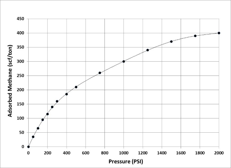
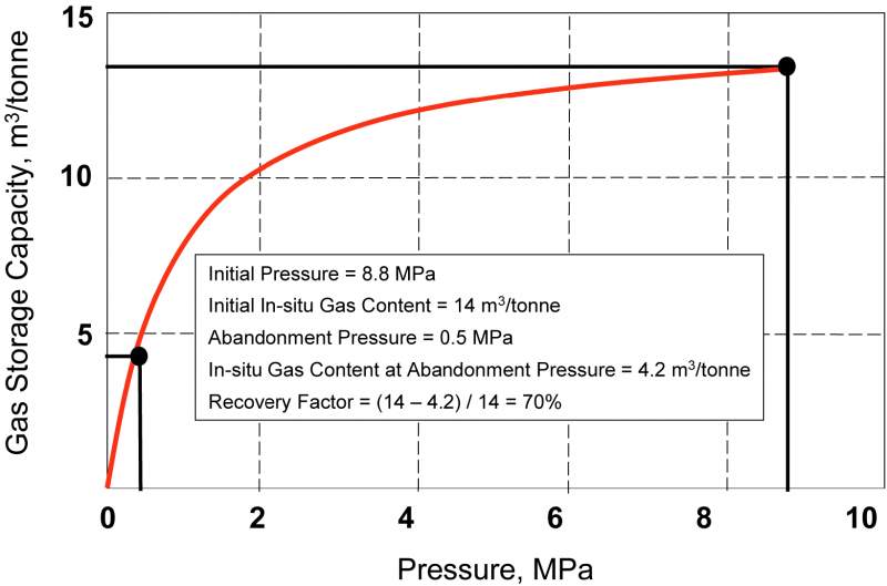
Remember that the methane is adsorbed onto the pore walls of the coal matrix and can only undergo desorption and become free gas capable of being produced as the pressure in the coal seam is lowered along the sorption isotherm. An isotherm is a plot of pressure versus methane storage capacity for any given coal. Figure 1 illustrates a typical methane isotherm.
 |
|
Because coals have a primary and secondary cleat system, coals experience directional permeability. Practically speaking, this means that a single well producing water and gas from a CBM reservoir will tend to produce from an elliptically shaped drainage area rather than a circular shaped one. Knowledge of the face cleat and butt cleat directions can provide better understanding of how best to place CBM wells to take advantage of the directional permeability when developing a field.
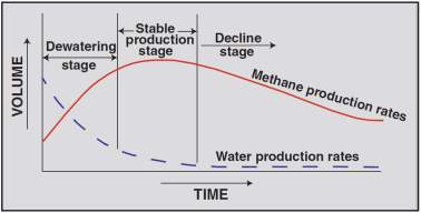
A conventional oil or gas well producing without natural or added pressure maintenance exhibits a production curve which generally begins at its highest point and declines over time. CBM production is unique because gas production initially increases for a period of time until a maximum production rate is reached. This increase coincides with the increasing desportion that accompanies the reduction in pressure as water is removed from the cleat system in the coal. The gas rate then declines similarly to a conventional well. Figure 2 illustrates this unique production curve.
 |
|
Coalbed methane reserves are most simply estimated by calculating a gas-in-place value and applying an estimated recovery factor. Gas-in-place resources are estimated using probabilistic methods. Log, core, cuttings, and seismic data are used to determine the areal extent, thickness, gas content and average density of the coal matrix. Multiplying these four parameters together yields an estimate of the volumetric gas in-place. If one can estimate the interconnected fracture porosity and the water saturation of that fracture porosity, a better estimate can be made.
Compared to shale and tight sand unconventional plays, the cumulative coal thickness across a CBM play may vary greatly; by a factor of two or more. Coal beds are often found with multiple seams that individually vary in thickness.
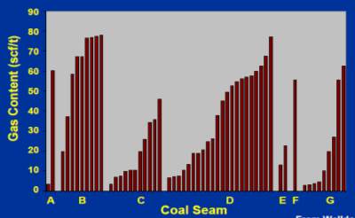
Gas content can also exhibit tremendous variability across a play, depending upon whether a coal seam is charged with thermogenic or biogenic gas, whether gas has been stripped-out or added by ground water movement, and the depth of burial (Figure 3). Gas content values are typically obtained from coal core-desorption measurements and values can range from less than 10 to more than 1,000 scf/ton, but is usually between 100 and 800 scf/ton.
 |
|
Coal density also varies greatly, but this is not always obvious from density measurements taken with a bulk density logging tool that measures only every half foot. Coal seams can have many thinner layers of variable high and low densities. This can lead to inaccurate estimates of gas in place unless these variations are incorporated into the estimate.
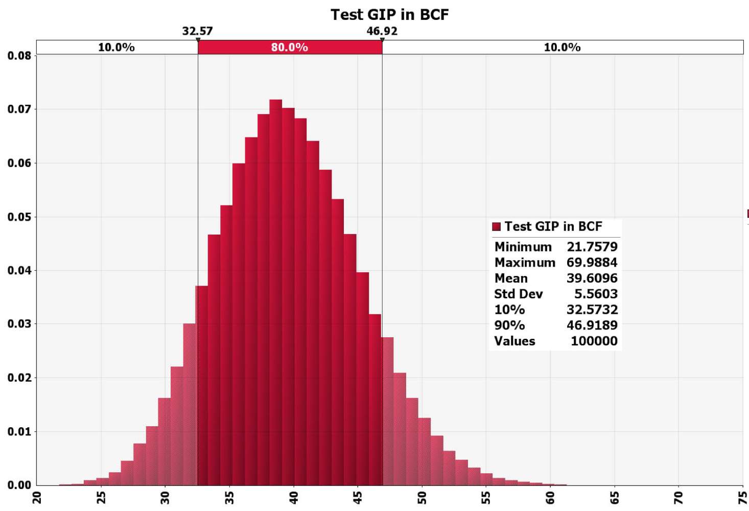
Probabilistic methods of CBM resource estimation attempt to capture the full range of possible resource values by taking into account the variations in thickness, gas content and density across the areal extent, which is typically the most well constrained factor (Figure 4).
 |
|
Such methods should also consider:
- The contribution of inter-bedded lithologies other than coal (e.g., tight sands and shales) that can provide significant additions to the gas in place.
- The coal matrix and cleat (fracture) permeability (e.g., anthracite coal has high gas content values but such low permeability the gas cannot flow at commercial rates).
- The degree to which the coal seam is undersaturated and will require a very long dewatering process before gas can be produced.
Initial estimates of CBM reserves may be generated from such resource estimates through the application of recovery factors based on analog field performance. If cores have been taken, the initial gas content data and desorption isotherm can be determined and used to estimate a recovery factor and reserves. The gas content from the isotherm at the expected abandonment pressure is subtracted from the total gas content of the core at the initial reservoir pressure. A recovery factor can be estimated by dividing this factor by the total gas content of the core (Figure 5), assuming the permeability throughout the coal seam drainage area is sufficient to support economic flow rates.
 |
|
However, many operators utilize reservoir modeling techniques to estimate per well reserves that incorporate the best information available regarding the key parameters identified above. These models are designed to accurately portray both desorption and diffusion of methane from the coal matrix and the flow of gas along the fracture network present in the coal seam.
As with conventional gas reservoirs, both original gas-in-place and recovery factor estimates are revised after multiple wells have been completed. This can be achieved via modeling or through a modified material-balance technique. Decline-curve analysis can be used in the mid-to-late stages of a coalbed methane field’s producing life, after the increasing gas rates that characterize early CBM reservoir behavior have been passed. Post-peak rate well data can be used to create type curves for estimating new well performance and individual well EURs.
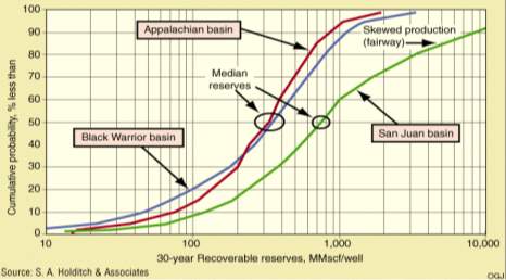
Per well reserves for CBM wells can vary widely across plays and within plays (Figure 6). Care must be taken to acquire sufficient pilot well data in the early stages of play development to accurately assess the future potential of the resource.
|
|
Subject 5: Development of Coal Bed Methane Reservoirs
The development of a CBM field begins with the exploration phase. Cores, well logs, gas content testing, and proximate/ultimate analysis provide are required inputs to estimate the total resource which may be available within the field or play. Most analysis of a field will be accomplished through drilling, coring and coal testing. Seismic exploration methods are not used as often since CBM fields are generally much shallower than other seismic targets, and coals themselves may not be imaged well on seismic if they are too thin.
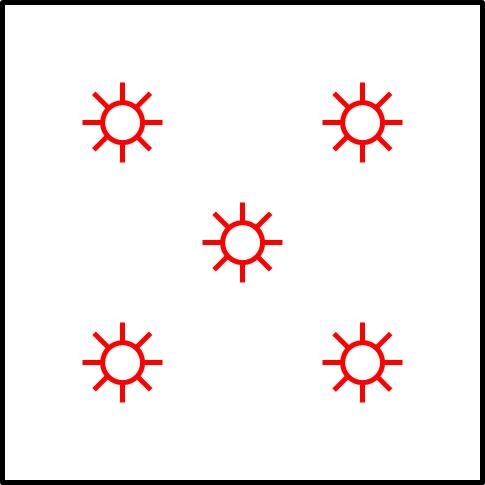
Once initial drilling and testing is complete and the target interval or intervals has been identified, the next step is generally a 5-spot pilot pattern. This pattern consists of four wells in a square, plus one well in the center (Figure 1). Remember that lowering the pressure in the coal seam by removing water is the most important first step in the development of a new field. A 5-spot pattern provides an excellent opportunity to remove water, as the center well of the pattern is assisted in its water removal efforts by the surrounding wells. The pilot 5-spot test may be drilled with a well spacing that is less than the spacing that will be used for full field development.
 |
|
The pilot 5-spot can provide good information about the productive capabilities of the formation, the permeability, as well as provide valuable information about how to develop the remainder of the field (e.g., size and type of pumps needed). If successful, the 5-spot should remain on production while the pattern of wells is expanded to whatever size is desired.
It is very important to note when developing a new field, that if the water production of the 5-spot is halted, the water in the seam will quickly recharge from outside the pattern. Production should be continuous as long shut-ins and sporadic water production rates will delay gas production.
The spacing of wells depends primarily on the extent of the cleat systems (permeability) and/or government spacing regulations for CBM wells. Drilling wells on 80 acre spacing is common in many CBM plays, but 40 and 160 acre spacing is also used. Because CBM is a resource play, CBM production is more consistent from location to location than conventional plays.
Coal Bed Methane Development Case History: San Juan Basin, USA
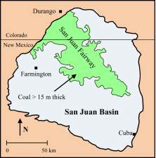
The San Juan Basin (Figure 2) is located in northern New Mexico and southern Colorado in the US. It produces from coals of the Cretaceous Fruitland formation, which is estimated to contain between 43 and 49 trillion standard cubic feet of methane. The Fruitland coals were developed as a CBM play during the late 1970s and 1980s as part of the tax-credit driven effort by the US government to increase domestic supplies of natural gas from unconventional sources.
 |
|
The thickest coal intervals occur along a northwest/southeast trend in the northeastern portion of the basin. Total coal thicknesses can more than 100 feet in this trend with individual seams sometimes more than 30 ft thick (Ayers, 1994). Fortunately, the thickest coal intervals were also higher rank coals that were over-pressured and exhibited high gas content and high permeability, in what is known as the San Juan “fairway” (Figure 3). The over-pressuring is caused by water recharge through outcrops along the northern margin of the basin which results in pressure gradients as high as 0.63 psi/ft versus a normal gradient of 0.465 psi/ft. This higher pressure enables a larger amount of gas to be sorbed in the coal. Gas content ranges up to 700 cubic feet per ton and permeability is generally >10 md from well-developed cleat systems.
San Juan basin coal seam gas contains up to 9.4% CO2 and 13.5% C2+ (Rice, 1993). Chemical analyses indicate that in the Fruitland coals thermogenic gas has been supplemented by secondary biogenic gas sources. Coal rank in the fairway ranges from medium- to low-volatile bituminous and the coals typically have low ash and high vitrinite contents. The coals are lower rank, thinner (20-40 ft) and underpressured southwest of the fairway, with gas contents of less than 200 scf/ton and permeability of generally less than 10 md.
 |
|
Initially, during the earliest phases of development, wells in the San Juan basin were cased and hydraulically fractured. Coal formation damage from drilling, cementing, and fracturing fluids was a common problem. In early 1986, Meridian Oil began a pilot project that pioneered the openhole dynamic cavitation completion technique (Close 1997). Resulting gas rates often exceeded 1 MMscf/D per well with some wells achieving 10 MMscf/D. It is estimated that 80% of the completions in the fairway area are cavity completions and that their average rate is four times that of hydraulically fractured wells (Kelso, 1994).
The most successful of these dynamic cavitation completions are in coal seams with minimum in-situ stress values of 2,080 psia, depths of 2,000 to 3,600 ft, and bottomhole pressures of at least 1,370 psia (Ramurthey, 1999)). In areas outside of the fairway where coal properties are less favorable, cavity completions have been largely unsuccessful. However, economic wells can still be drilled and produced outside of the fairway if higher permeability sweet spots are located.
The San Juan basin currently (2016) produces about 300-400 Bscf/year from more than 3,500 wells. This is down from a peak of about 1000 Bscf/year in 10-15 years ago. Good wells in the fairway area typically had a peak rate of 6,000 Mscf/D with an ultimate recovery of about 15 Bscf on well spacing of typically 320 acres. Abandonment pressures in the fairway are projected to be less than 100 psia, resulting in ultimate recovery factors of greater than 70%.
An average well in the San Juan basin produced at an initial rate of 100 to 400 Mscf/D and 40 to 400 BWPD (Ramurthy, 1999). Production typically doubled within 2 to 4 years in fairway wells, while flat initial production profiles are more characteristic of nonfairway wells. Decline rates vary, ranging from < 5% to >20% per year.
Cite This Work
To export a reference to this article please select a referencing stye below:
Related Services
View all


Related Content
All TagsContent relating to: "Environmental Science"
Environmental science is an interdisciplinary field focused on the study of the physical, chemical, and biological conditions of the environment and environmental effects on organisms, and solutions to environmental issues.
Related Articles

DMCA / Removal Request
If you are the original writer of this dissertation and no longer wish to have your work published on the UKDiss.com website then please: