Looping Elimination Mechanism During Colonoscopy Procedure
Info: 13225 words (53 pages) Dissertation
Published: 9th Dec 2019
ABSTRACT
From the world of scopes “Colonoscope” is the best equipment for the diagnosis as well as for the biopsy of diseases inside the colon. One of the most common and ongoing challenge during the colonoscopy procedure with this equipment is the formation of loop, that forms between the colon and colonoscope. Due to the loop formation, the further insertion of the colonoscope towards the area of interest would become quite impossible. As a result, the risk towards the perforation of the colon increased and stimulate pain to the patient. Whereas on the other hand the time duration of the procedure will also get effected due to the loop formation. Currently there are some manufacturers that addressed the loop formation problem and modified their colonoscope according to it, which are available in the clinical work places. However, experimental evaluation comes up with the results that these introduced modifications in colonoscope does not work up to that extent which is required practically. This is the main motivation for the research presented in this project report.
This project is about the interfacing and embedding a system with the colonoscope that will help doctors and colonoscopist to perform successful colonoscopy procedure without facing any looping problem, if any problem occurs system will help to identify problem. The embedded system will have a Colonoscope Force Monitor (CFM) to monitor the applied Force and Torque, whereas the resultant Friction Force will be observed by the Force/Pressure Sensors. The data (force and friction) will then forwarded by the interfacing system to the computer that will make a comparison display between applied force and resultant friction force on the colonoscope.
INTRODUCTION
To diagnose and evaluate the colorectal diseases of the lower Gastrointestinal (GI) area, colonoscopy is one of the best system designed. The colonoscopy system is designed in such a way that it is not only used for the diagnosis purpose, but for the treatment purpose as well. Like the removal of the polyps is done through the instrument section commonly known as biopsy wire guide (Obstein & Valdastri, 2013). While performing colonoscopy the failure rate is about 10% (Park, et al. 2013), the biggest challenge among these failure is the loop formation of the colonoscope shaft that creates obstruction to visualize the entire colon and it is also responsible for the colonic wall injuries and perforation. (Sato, et al. 2006) (Mitchell, et al. 2002).
Colon Anatomy:
The “Colon” commonly known as “large intestine” is a long flexible organ of about 1.5 meters (5 feet) that extends from Cecum to the Anus of the lower gastrointestinal tract (Jones, 2017). The digested food from the small intestine is forwarded to the colon, where the process of water and ions absorption take place to finally form the feces. Based on the definition of anatomy, the colon is divided into four parts which are known as Ascending Colon, Transverse Colon, Descending Colon and Sigmoid Colon.
The track of the colon starts from the ascending colon section which has retroperitoneal structure (fixed to the retroperitoneum) that rises in the upward direction from the cecum. At the right lobe of the liver, ascending colon make the turn of 90 degree to the horizontal direction and meet with the transverse colon. This turning is known as Hepatic Flexure.
The transverse colon which has intraperitoneal structure, starts from the hepatic flexure, travels over the abdomen and extends to the spleen where colon turns again at an angle of 90 degree vertically downwards and join with the descending colon and that turning is known as Splenic Flexure.
The colon travels from the splenic flexure towards the downwards direction for that reason this section is known as descending colon. Just like ascending colon, it is also retroperitoneal in structure located in front of the left kidney and ends at the Sigmoid Flexure. The sigmoid colon is the last section of the gastrointestinal tract, which is located at the lower left quadrant of the abdomen.
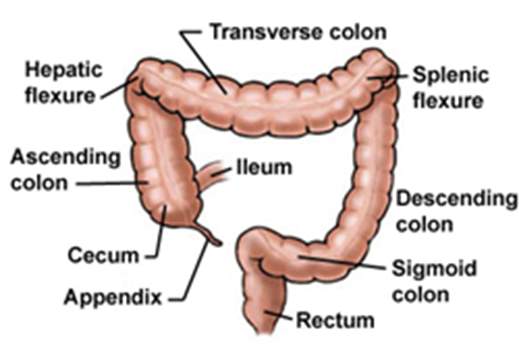
Figure 01. Anatomy of the Colon
(Retrieved from: http://www.yoursurgery.com/ProcedureDetails.cfm?Proc=17)
Colonoscopy System:
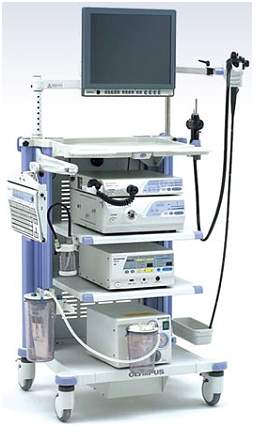
The general colonoscopy system consists of major sections like LCD monitor for the real-time display, the Video System section where the video processor converts the electrical signals from the scope into video signals and transfer them to LCD for display, the Light Generation Source section uses a xenon lamp to produce light similar to natural light which is transferred to the scope’s distal end, the Suction System section incorporates a pump for supplying water and air to the scope and finally the Scope Section.
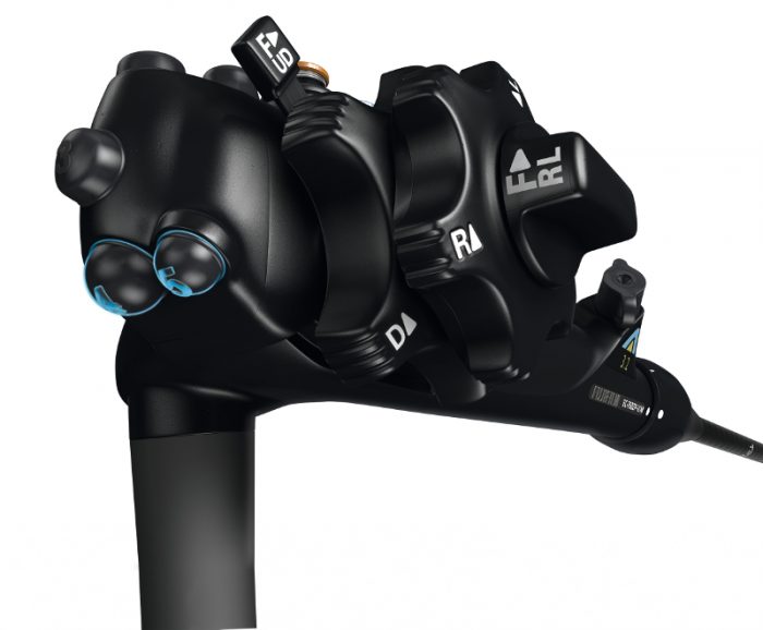
The scope section (colonoscope) itself can divided in four sections – the universal Cord and Plug Section, Control section, Insertion Section (commonly known as Shaft) and Bending Section. The control section of the scope contains all the hand controls that is required for the navigation, instrument (biopsy), air & water controls and bending of the distal end of the scope.
The above described sections are shown in the following figure 02. Furthermore, the scope section will be discussed more in detail as this is the only part which is the area of interest of this report.


LCD Monitor
Hand Control Section
Universal Cord and Plug Section
Video System Section
Insertion Section (Shaft)
Light Source Section
Bending Section
Suction System Section
Figure 02: Olympus Corporation, USA Colonoscopy System (Ottawa Endoscopy & Day Surgery Centre, 2011)
Retrieved from: (http://www.ottawaendoscopy.ca/services.htm)
Colonoscope:
The length of the insertion tube (containing the insertion and bending sections) is about 130 centimeters (51 inches), that is composed of major components like digital wires channel for camera, optical fibers channel for light, instrument (biopsy) channel, air channel, water supply & suction channels and the Bowden cable for flexible movement (Jechart, 2004). At the tip side (distal end of the scope) for the camera channel, a lens is present with the lens cover along with a video chip that produces the image (Jechart, 2004).
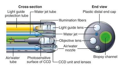
Figure 03: Tip of the Colonoscope and its cross-section (Gastroenterology and Hepatology, 2015)
Retrieved from: (https://clinicalgate.com/how-endoscopes-work/)
The bending section is composed of the last 15 centimeters (6 inches) of the insertion tube and made specifically flexible for bending in all four direction that allows exclusively better steering during the use in gastrointestinal tract (Jechart, 2004). Therefore, the operator could bend the tip of the colonoscope about 160 degrees to right/left sides and 180 degrees to up/down direction (Jechart, 2004).
The control head section of the scope contains all the necessary functions that are highlighted in the following figure 04.
Brake / Locking device (up/down)
Suction button


Air/Water button
Brake / Locking device (right/left)


Freeze button
Instrument Channel
Function button
Up/down bending controller
Right/left bending controller
Figure 04: Hand control unit of the colonoscope (Fujifilm Europe Gmbh, Expo21xx online exhibition)
Retrieved from: (http://www.expo21xx.com/news/fujifilm-eluxeo-endoscopy-system/)
Procedure of Colonoscopy:
The process of colonoscopy initiates with the intubation of a colonoscope from the anus via the colon to the cecum, which is considered as the least invasive procedure for detecting the colorectal diseases. Throughout a comprehensive colonoscopy procedure, the insertion shaft is inserted into the anus then pushed forward through the rectum, sigmoid colon, descending colon, transverse colon, ascending colon and to the cecum (Hoff, et al. 2011).
The colorectal diseases would be just a simple polyp (depends on the condition the simple polyp could be remove from the colon via biopsy instrument) or might be the related to the colon cancer (Cheng, 2013). Following figure 05 illustrate some examples of the colon diseases diagnose by colonoscope.

Flat Adenomas
Juvenile Polyp
Malignant Polyps
Figure 05: Different types of colorectal diseases (Messmann, 2006, Atlas of colonoscopy)
Retrieved from: (http://www.colonoscopy.ru/books/rar/Atlas%20of%20Colonoscopy.pdf)
To perform the colonoscopy procedure, two methods are commonly used in clinical practice known as one – person and two – person colonoscopy procedure (Cheng, 2013).
In the one – person colonoscopy, the colonoscopist performs the investigation alone, handling the controls of angulation and options of the hand control by one hand and inserting, push/pull or twisting the scope’s shaft with the other hand. During the procedure, it is commonly observed that the colonoscopist uses the right hand to insert the scope where as the scope’s distal end orientation and angulation is control with the left hand (Hoff, et al. 2011).
In the two – person colonoscopy, a colonoscopist (considered as first person) and an assistant (considered as second person) performs the examination, the colonoscopist or gastroenterologist has the hand control section of the scope, while the assistant pulls and pushes the colonoscope according to the commands given by the first person (Hoff, et al. 2011).
By comparing the two methods, during the two – person procedure the perfect coordination is difficult to accomplish. Therefore, the one – person method usually provides the best results due to the strong coordination achieved for the two operations performed by a single person (Cheng, 2013). Furthermore, the procedure caused abdominal pains and injuries are reported more in two – person rather than one – person method (Hoff, et al. 2011).
Loop formation during colonoscopy procedure:
Despite of the fact that colonoscopy system is the major tool in clinics for the diagnosis of colorectal diseases, the failure rate of the procedure is still more than 10 % means among the one of the ten procedures the scope is unable to reach to the last section of the colon (cecum), and the main reason behind the unsuccessful procedures is the formation of scope’s loop in the colon (Church, 1993).
Naturally the colon shape is deformable, therefore the formation of the loop arises when the colonoscope encounters the colon wall and results in the generation of the resistive force of friction. The further advancement of the scope with the frictional resistance along with the factor of the existing shape of the shaft and colon, this leads towards the formation of loop and eventually the distal tip of the colonoscope will not able to move further, whereas in some cases the resistive force will forces the shaft in backwards direction (Moser, et al. 2012).
Formation of loop in colon are of different types among them alpha – loops and N – loops are the most common one, while U – loops, gamma – loops, reverse alpha – loops and reverse gamma – loops are also the types of loop formation in colon. According to the study done by Koichiro Sato and his team, 60% of the colonic loop formation occur in the sigmoid colon section with the forming of alpha or N – type loop, whereas transverse colon section contributes 33% with the U – loop formation. Creation of reverse alpha – loop is 8%, whereas the contribution of gamma and reverse gamma – loop is only 1% (Sato, et al. 2006).
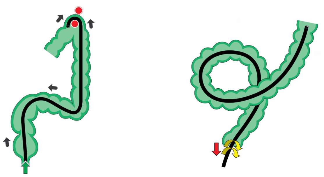
N – loop formation in colon
Alpha – loop formation in colon
Figure 06: Alpha and N type loop formation (Overcoming the Sigma – part 2, Endoscopy colon explorer)
Retrieved from: (http://www.endoscopy-colon-explorer.com/overcoming-the-sigma-part-2/#lightbox [1107] prettyPhoto[gallery1]/7/)
James M. Church explained the four ways for countering and minimizing the loop formation during the procedure that are: exerting abdominal pressure, holding the patient’s breath, turning the patient to the right side and turning to the left side (Church, 1993). The different combinations of these techniques are used to successfully resolve the loops.
Effects of loop formation:
One study reflects that 91 out of 100 patients that goes under the procedure of colonoscopy have experienced the looping problem (Shah, et al. 2000). During the procedure patients are provided anesthesia but due to the loop formation the patient gets uncomfortable therefore for that reason the level of anesthesia must be raised, and prolongs the colonoscopy procedure time of duration that in turns increases the risk associated due to the time exposure to anesthesia (Sato, et al. 2006).
Looping also causes pain to the patient because of the stretching the mesentery of colon, which is the set of tissues that is formed between the wall of colon to the wall of the abdomen (Eickhoff, et al. 2010).
The colonoscopist or gastroenterologist will exert force by twisting inwards and outwards direction to the colonoscope shaft that will enhance the risk level of damaging mucosa and inner tissue lining of the colon (Park, et al. 2007), while in few cases the Splenic injuries has been reported (Shankar & Rowe, 2011). It is also reported that due to the additional force exerted by the tip of the scope along with the colon wall stretching, the outer lining of the colon called Serosal get damaged or injured (Livstone & Kerstein, 1979).
Research Objective:
When we analyze different colonoscope in the market then we realize that there are various colonoscopies are available by different manufactures that addressed the loop formation problem in there colonoscope system and they are now adapted by the clinics and hospitals for medical examinations as well. Among them some are as follows:
- Over – tube Colonoscope
- Capsule Endoscope
- Virtual Colonoscopy
- Aer – O – Scope
- Neo Guide Endoscopy System
- Image Guided Colonoscopy
However, clinical analysis and experimental assessment reveals that the above mentioned colonoscope models does not up to expectation of Gastroenterologists in terms of overcoming loop formation (Cheng, et al. 2012). Analysis done by Cheng and his team discloses that the solutions that are available in market have missed the important factor of engineering perception known as self-locking of the colonoscope and colon (Moser, et al. 2012).
To overcome these issues, the suggested model must be fulfilling the definition of operator-assisted colonoscopy. In this new paradigm, the operator or gastroenterologist would be able to get some additional parameters on display such as the exerted force by the operator, resultant friction force (between colon and colonoscope) and their comparison.
From the aforementioned research analysis and suggestions, following two objectives will be proposed in this report:
- Analyse and evaluate the available colonoscope devices and their solutions for eliminating the loop formation from the prospective of engineering design methodology.
- To develop an idea of an operator – assisted colonoscopy model that would be embedded on the shaft of the colonoscope and interface with the computer to monitor the force angle and compares it with the friction angle. The display of these angles will help the operator to assist him to keep the driving force greater than the friction force for avoiding the loop formations.
Organization of the report:
The report will be composed of different chapters, the organization of the report will be described as under:
- Basic introduction of Colonoscopy system and its procedure, problems related to colonoscope and effect of loop formation.
- Analysis and evaluation of the colonoscope devices for looping elimination available in the market through the concept of Engineering Design Theory and Methodology.
- Idea of a new equipment, modelling and designing methodology to get proper idea pertaining to new designed procedure.
- Simulation of the introduced idea.
- Future work
- Conclusion
- References
CAUSES OF LOOP FORMATION AND EVALUATION THE EXISTING COLONOSCOPY DEVICES
In this section, the evaluation will be done of the available design and devices that focuses the looping elimination issue during the colonoscopy procedure. Before the evaluation the causes related loop formation will be explain with its mathematical explanation. For the evaluation of the devices, first we need to establish criteria whose structure is based on the theory presented in Advance Engineering Design and Methodology (ME886) course known as Axiomatic Design Theory (ADT).
Causes of loop formation:
Generally, loop formation initializes when the colonoscope shaft reaches to the sigmoid colon. Where the experienced physician or gastroenterologist can resolve the formed loop and able to pass into the adjacent descending section of the colon. Once the scope reaches at the splenic flexure of the colon which has a sharp turn, the scope experiences looping once again. Furthermore, another formation of loop has been observed at the sharp turn of the hepatic flexure. The formation of the loop in the colon can be explained by the self-locking mechanism (Moser, et al. 2012).
Self-locking Mechanism:
When the colon and colonoscope meet at contact point they will experiences force of friction because both the objects are deformable, that results may be either static or dynamic friction. At the point of contact between colon and colonoscope generally two states are formed in the tangential contact which are defined as slip state and stick state (Cheng, et al. 2012).
Slip state occurs when tangential force is greater than the limit of static friction force, which is defined as the product of the normal force with the static frictional coefficient. In the slip state, there will be a possible slip occurs between the colon and the colonoscope. Therefore, for that reason the shaft of the colonoscope has the possibility to move forward along with the friction force.
Stick state is the displacement of two contact points when both are equal to zero. This stick state usually occurs in sigmoid colon, as a result the colonoscope remains stationary and unable to move forward.
This friction force can be determined by the multiplication of dynamic frictional coefficient and normal applied force to the point (Dequidt, et al. 2009).
Mathematical analysis of Stick and Slip states:


F(nor)
Colonoscope
F1
P = [Xp, Yp, Zp]
Contact Point α
Sigmoid Colon
F2
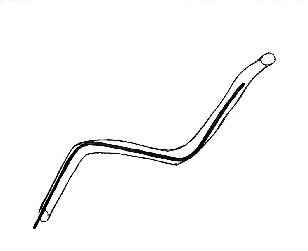
Figure 07: Analysis of the force contact between colonoscope and colon near sigmoid colon.
Let us consider the above figure 07 to establish the mathematical analysis of Stick and Slip states. Suppose there is a contact between colonoscope and colon at point P and this point frame is represented as Xp, Yp and Zp. Where Xp is a normal direction and its force component is F(nor). Whereas Yp and Zp are the two component directions representing the tangential direction of the colonoscope at the point of contact which are perpendicular to each other (Cheng). The force component F1 and F2 are the respectively representing forces along these component directions.
Now consider the general equation of the force of friction:
F friction = μ × N Eq. (1.0)
Where µ is known as coefficient of friction and N is the normal force.
By applying Eq. (1.0) on the figure 07, the state of frictional force can be defined as follows (Dequidt, et al. 2009):
F1 × F2F(nor) ≥ μ b
Where the (a) is the mathematical explanation for occurring of Sticking Friction and (b) indicates the occurrence of Slip Friction.
Let us consider
α
(alpha) as driving force angle and
β
(beta) as friction angle.
Therefore defining
F1 × F2Fnor =tanα
and on the bases of the definition of friction angle:
tanβ = μ
This results in the following relationship:
tanα ≥ tanβ d
Where (c) represents the Sticking State and (d) directs the Slip State. On the bases of the above equations if the condition occurred when
α < β
then the shaft of the colonoscope will not move forward and remain stationary, this event is known as Self-locking.
Due to the formation of the self-locking state, the physician will apply an additional unwanted increase in the driving force to drive colonoscope forward and this would result the swelling of the colon internal tissues.
On the bases of the above analysis it is been concluded that for avoiding loop formation and for the smooth procedure of colonoscopy, the Driving Force Angle must be remaining greater than the Friction Force Angle.
Evaluation of existing devices for loop elimination:
Advanced Engineering Design and Methodology is a subject which is point of interest for every organization, especially for those who are having an immense research in this area related to innovation, designing of engineering products, modelling and enhancement or modifications related to engineering design and various processes.
Dr. Suh Nam Pyo introduced the concept of axiomatic design theory for systems and developed the relation between “What we want to achieve?” and “How we want to achieve?” (Suh, 1998). The following table can explain this concept in more detail:


Axiomatic Design Theory
What we want to achieve?
How we want to achieve?


Leads to
Leads to
Functional Requirements (FRs)
&
Constraint Requirements (CRs)
Design Parameters (DPs)
The constraint requirement can be described as the limitation or restriction of a system, and it provides the conditions criteria for the system where the functional requirements are achieved. In short, the design theory could be defined as “the design process to develop the design parameters (DPs) for achieving or fulfilling the functional requirements (FRs) under the defined constraint requirements (CRs)” (Suh, 1998).
The structure of the evaluation criteria for the devices that provides the solution of looping of the colonoscope could be defined by the following check points:
- The causes of loop formation are considered as Functional Requirements (FRs) along with Constraint Requirements (CRs).
- The available or existing design and their solution are considered as Design Parameters (DPs)
Axiomatic Design Theory (ADT) will evaluate the design parameters DPs of the given system by providing the FRs and CRs (Suh, 1998). The Axiomatic Design uses two Axioms defined in the following table:
Axiomatic Design


AXIOM 1:
The independence Axiom
AXIOM 2:
The Information Axiom


Maintain the independence of the Functional Requirements (FRs)
Minimize the information content of the design
The validity and reliability of a design is explained by the Axiom 1, whereas the Axiom 2 describe the best possible design among the different design options with respect to its material availability, manufacturing cost etc (Suh, 1998).
Now we need to develop the parameters of DP, FR and CR for the colonoscopy system that we need to design for the loop elimination, through which the Axiomatic Design Theory will compare the parameters of the existing devices. As we have already defined in the self-looking mechanism section that for the prevention of the loop formation is only be occur when the driving force angle must be kept higher than the friction angle, therefore the Functional Requirement (FR) is defined as:
|
FR: The distal end of the colonoscope must be keep away from stick state |
The above defined FR need to be fulfilled by the following Constraint Requirements (CRs):
|
CR1: Colonoscopy procedure Time |
|
CR2: Colonoscopy procedure Cost |
|
CR3: Biopsy function |
|
CR4: Patient Safety with the examination environment |
Finally, the Design Parameter (DP) for the required colonoscopy system is defined as:
| DP: To make sure while pushing the colonoscope in forward direction, the driving force angle remain greater than the friction force angle |
Analyzation of Virtual Colonoscopy:
Virtual Colonoscopy also known as Computed Tomographic Colonoscopy, in which the X-Ray imaging technique called CT Scan is use for creating the 2D or 3D images of the rectum and the colon. In this test procedure, a small tube is inserted through anus towards the rectum, for getting better and improved image quality the inflation of large intestine could be done by this tube.
Virtual colonoscopy is done to diagnose the colon cancer, intestinal discordances and the growth of polyp in colon. However, this type of colonoscopy procedure has several drawbacks with respect to the diagnostics of the intestinal diseases. First, the inflation could have the major chances to create perforation in colon. Secondly, X-Ray radiations are involved in this procedure which is harmful form the health aspect. Third due to the colour variation, the mucosa detection is nearly impossible by the X-Rays which indirectly losses the information of various abnormalities. Another issue for the CT scan is that the information related to the polyps smaller than 10 mm are unable to detect and finally this method does not have the biopsy option for removing polyps (Halligan & Fenlon, 1999).
By analysing and evaluating the virtual colonoscopy than the design parameters of the required colonoscopy system we get the results that the Design Parameters (DPs) of the virtual colonoscopy system fail to fulfil the three required CRs which are as follows:
|
CR2: Colonoscopy procedure Cost |
|
CR3: Biopsy function |
|
CR4: Patient Safety with the examination environment |
Analysis of AER – O – SCOPE Colonoscopy System:
Aer-O-Scope Colonoscopy system has been manufactured by GI-View, Ltd., Israel, a disposable self-propelled colonoscope for Gastrointestinal (GI) views (Pfeffer, et al. 2006). This system consists of disposable scanner and PC based workstation. The disposable part is connected to the workstation via an ultra-flexible multi-luminal cable that supplies gas, water, suction and wires for the camera. Through a joy stick the physician has the complete control over the disposable scanner orientation, navigation and visualization.
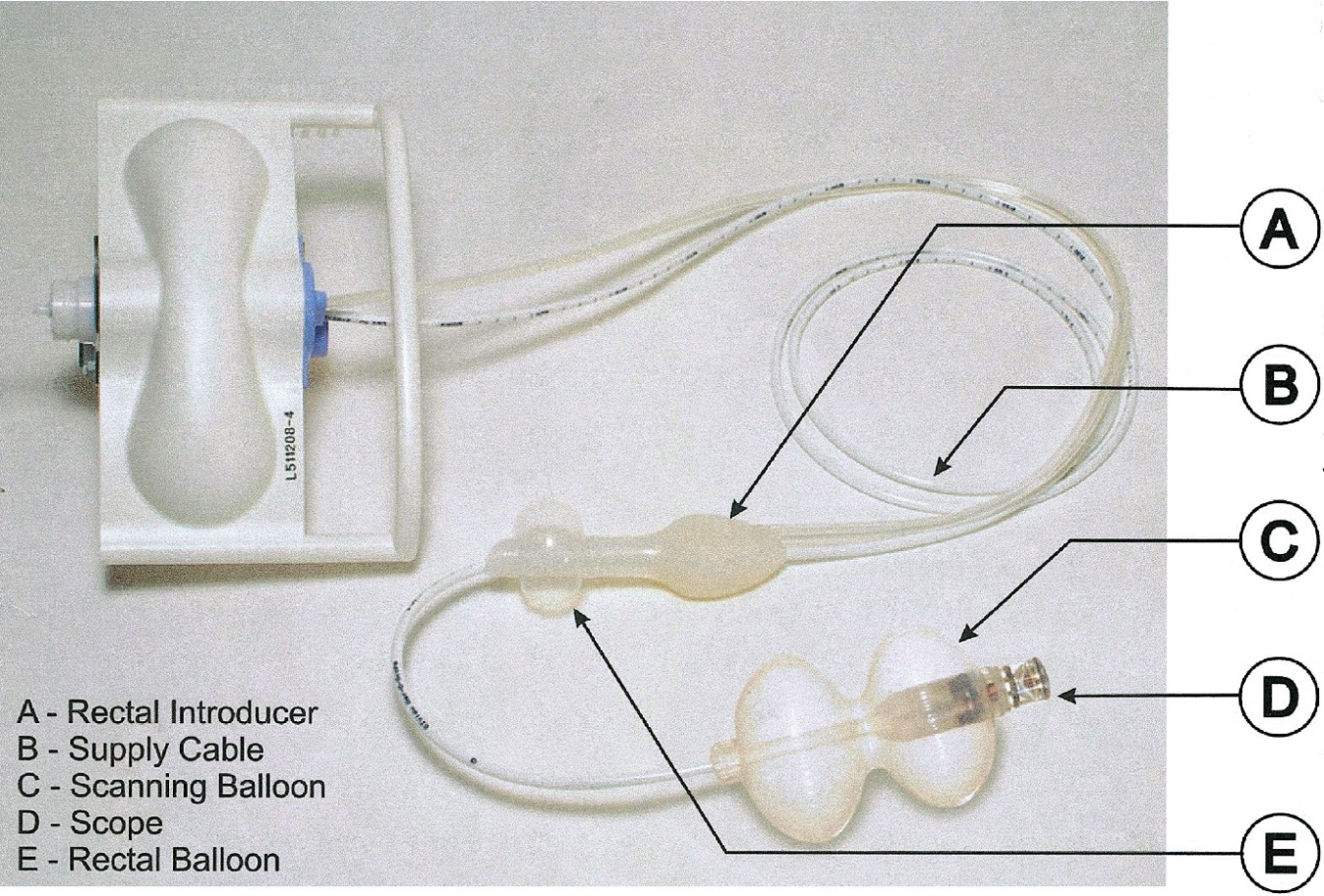
Figure 08: Disposable components of AER – O – SCOPE (Vucelic et al, The Aer-O-Scope, Gastroenterology 2006)
Retrieved from: (http://metcorner.gastro.org/article/S0016-5085(05)02528-X/fulltext)
For the driving mechanism, the two balloons are attracted to the cable, one of which is inflated and fixed at the rectum area where as the second balloon is mobile that slides with the scanner. The Carbon dioxide (CO2) gas is filled between the balloon area for driving the scope smoothly. The current available model of Aer-O-Scope Colonoscopy system only have the diagnostic capabilities and does not have polypectomy and biopsy options.
Although the design parameters DPs of the Aer-O-Scope colonoscope system has fulfilled the majority functional requirements (FRs) of the ADT, but the further evaluation revels that this system does not have any option for biopsies, therefore DPs of this model has failed to comply major (CRs) of the required colonoscopy system.
|
CR3: Biopsy function |
Analysis of NeoGuide Endoscopy System (Computer assisted colonoscopy):
NeoGuide Systems, Inc., USA, develop a colonoscopy system known as NeoGuide Endoscopy System that has a unique feature of computer assisted and controlled colonoscope tube. The colonoscope shaft or tube is composed of 25 segments followed by the tip of the scope, which is controlled by the control unit. All the 25 segments follow the scope’s tip angle, orientation and navigation through a computer bases software that is based on the principle of “follow the leader”. Therefore, each segment will organize itself according orientation of the tip (Van Dam, et al. 2006).
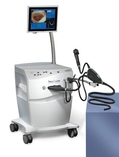
Figure 09: Computer-Assisted Colonoscopy (The NeoGuide Endoscopy System: Results of the First Human Clinical Trial).
Retrieved from: (https://www.researchgate.net/publication/6643701_Computer-Assisted_Colonoscopy_The_NeoGuide_Endoscopy_System_Results_of_the_First_Human_Clinical_Trial_PACE_Study)
Although the concept and the design of NeoGuide Endoscopy System eliminates the loop formation in the colon, but the main drawback is that the orientation of the scope cannot be changed randomly during the procedure in the colon as the shape is controlled by the computer.
The Design Parameter (DP) for that system is define as the shaft of the colonoscope follows the trajectory of its tip or in other words it could be defined as, the route of the colonoscope body is dependent on its tip (AXIOM 1 fails). However, the evaluation of the design of this system fulfils all the four constraint requirements (CRs) of the colonoscopy system, but the design parameters (DPs) of NeoGuide Endoscopy System fail to meet the Functional Requirements (FRs) of the Axiomatic Design Theory (ADT).
Analysis of Colonoscopy with Image Guided Techniques:
For the navigation and loop elimination of the colonoscope, image guided techniques have been used to create 3D images of the scope inside the colon during the colonoscopy procedure. These real time 3D images are acquired either by using X-Ray based Fluoroscopy system, or by using Magnetic Endoscopic Imaging (MEI) (Saunders, et al. 1995) technique which is first introduced by Olympus Corporation, USA.
Following are the two image guided techniques available in the market:
1. ScopeGuide Colonoscopy, based on Magnetic Endoscopic Imaging.
2. Fluoroscopy Guided Colonoscopy, based on X-Ray radiations.
Analysis of ScopeGuide Colonoscopy System:
ScopeGuide is an exclusive technology designed by the Olympus Corporation, USA. It is designed to provide real time 3D image of the shape of colonoscope inside the colon. The real time 3D image is made possible through built-in electromagnetic coils imbedded on the shaft of the colonoscope, that generates low frequency magnetic field. This technique is commonly known as Magnetic Endoscopic Imaging (MEI) (Shah, et al. 2000).
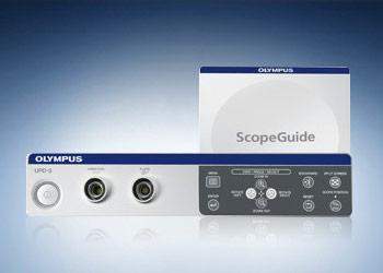
Figure 10: OLYMPUS ScopeGuide UPD-3 (Olympus Corporation, USA)
Retrieved from: (http://medical.olympusamerica.com/products/scopeguide-upd-3)
The magnetic pulses are received by the receiver dish system, which are then transmitted to the processor or workstation for generating 3D representation of the scope alongside the colonoscopy video image. The physician can change the orientation to control the loop formation by viewing the 3D real time images of the colonoscope.


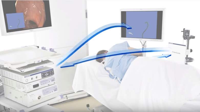
Colonoscope 3D real time view
Processing unit or Workstation
Receiver
Figure 11: 3D image formation by using ScopeGuide. (Olympus Corporation, USA)
Retrieved from: (http://medical.olympusamerica.com/technology/scopeguide)
However, ScopeGuide colonoscopy system is the most recent technology for the loop elimination but still the operator is unable to identify the required push or pull forces during the colonoscopy procedure, additionally the patient is exposed to the electromagnetic field. Therefore, for that reason the ScopeGuide system does not fulfil the functional requirements (FRs) of Axiomatic Design Theory (ADT). Furthermore, the design parameters (DPs) of the ScopeGuide system fail to meet the required constraint requirements (CRs) that are as follows:
|
CR2: Colonoscopy procedure Cost |
|
CR4: Patient Safety with the examination environment |
Analysis of Fluoroscopy Guided Colonoscopy:
The technology of X-Ray based fluoroscopy has been used with the colonoscopy system in order to guide the tip of the scope (Lim, et al. 2013). The images obtained by the fluoroscopy system allows the operator to precisely locate and control the orientation of the colonoscope tip, whereas the procedure time and procedure cost will increase using fluoroscopy system. Moreover, the patient need to expose with the radiations for guiding the colonoscope (Cirocco & Rusin, 1996).
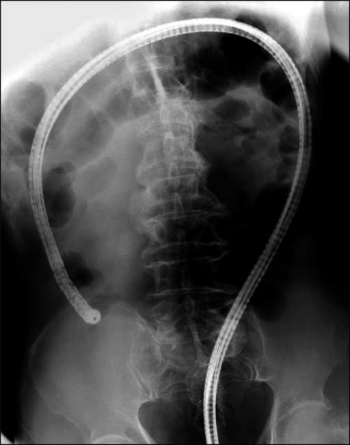
Figure 00: Fluoroscopic view of a patient with the successful colonoscopy trajectory. (Lim S.G. et al, 2013).
Retrieved from: (https://openi.nlm.nih.gov/detailedresult.php?img=PMC3661963_gnl-7-311-g001&req=4)
In this procedure, the guidance of the colonoscope is dependent on the fluoroscopy system. For that reason, the fluoroscopy guided colonoscopy fails to fulfil the Functional Requirements (FR) of Axiomatic Design Theory (ADT).
Furthermore, the Design Parameters (DPs) of this system fail to meet the required Constraint Requirements (CRs) of the colonoscopy system that are as follows:
|
CR1: Colonoscopy procedure Time |
|
CR2: Colonoscopy procedure Cost |
|
CR4: Patient Safety with the examination environment |
Analysis of Capsule Colonoscopy System:
By the advancement in the field of data transformation and micro-electronic technologies, the field of medical devices have been significantly influenced on the manufacturers and medical field personals. Capsule Colonoscopy is the best example for these advanced technologies, the patient need to swallow the capsule through water and then it self-propelled from the stomach towards the gastrointestinal tract by the natural procedure without feeling any pain and finally it will excrete out naturally. This is considered as the non-invasive technique that collects the information for the diagnosis of the complete gastrointestinal tract (small intestine and colon) [53 – 54].
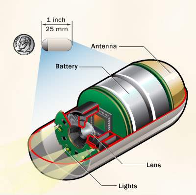
Figure 00: Capsule Colonoscopy Camera (Mayo Foundation for Medical Education and Research)
Retrieved from: (http://www.mayoclinic.org/tests-procedures/capsule-endoscopy/multimedia/capsule-endoscopy-camera/img-20008293)
The capsule consists of a small tiny wireless camera, batteries, lights for illuminating digestive tract and transmitter and these all components are fit into a vitamin size swallow able capsule. The camera takes hundreds of pictures of the gastrointestinal tract and then the data of pictures were transmitted wirelessly to the sensors that are placed on the abdomen of the patient. These sensors are connected to a recording device that is place in the belt wear around the patient’s waist, finally after few hours data has been transferred to the viewing workstation computer for the diagnosis purpose [55 – 56].
Medtronic, USA (previously known as Giving Imaging Ltd., USA) has developed a first capsule for colonoscopy known as PillCam Colon, that has a length of about 25 mm and diameter around 11mm [57 – 58]. Later, Olympus Corporation, USA, has launched their product namely EndoCapsule which have the same dimensions of PillCam [59].
In spite of the fact that, the design of the capsular colonoscope reflects the present era technology, but still it has some drawbacks when we compare it with requirement of the colonoscopy procedure. The main problem is that use of the capsule restricts to the diagnosis only, whereas non-invasive biopsy is the constraint requirement for the colonoscopy system. Secondly, the doctor or gastroenterologist could not get the closer images of the area of interest [61]. As the capsule is a compact, tiny and mobile unit so it has the limitation of the battery power, that could provide continues power to the camera, light and transmitter up to 6 to 8 hours [60].
The driving mechanism of the capsule colonoscopy is self-propelled and it does not need any external force for penetration, therefore it is free from the self-locking phenomenon. As its design parameters (DPs) is based on self-propelled concept, thus it fulfils the functional requirements (FRs) of the Axiomatic Design Theory (ADT). Furthermore, the evaluation revels that the design parameters of capsule colonoscope fail to compete the two constraint requirements (CRs) of the required colonoscopy system that can be defined as:
|
CR1: Colonoscopy procedure Time |
|
CR2: Colonoscopy procedure Cost |
|
CR3: Biopsy function |
Comparison of the Evaluation:
DESIGN MODEL OF COLONOSCOPE WITH FORCE AND FRICTION MONITORING SYSTEM TO AVOID LOOP FORMATION
After analyzing various concepts and types of colonoscopy systems available in medical field, it has been observed that loop formation is a very vast and common problem available in this area which create problems for colonoscopist to perform the procedure.
To overcome this problem equipment is suggested in this report which will be a best fit for the current principle of colonoscopy that helps to overcome the looping error and problem.
The suggested monitoring system here will be integrated with the colonoscope and will help measuring the applied force by the colonoscopist and the friction occurs between colon and scope’s tip and finally display their numerical values for comparison. So, if the driving force will be greater than the frictional force the loop formation will be avoided.
Benefits of the new integrated system are described as under:
- Advanced Indication of Loop formation.
- Real Time Mechanism.
- Applied Force and Resultant Forces will be in display form, therefore the colonoscopist or operator can be informed during procedure.
- Smooth Procedure
Basic Idea of new system in Block Diagram:
Colonoscopy System


Colonoscope (Shaft)
Colonoscope Force Monitor and Flexible Sensor


Driving Force Angle kept Greater Than Friction Force Angle
Process Applied to Human Body


NO
Colonoscope proceed smoothly in Forward Direction

Formation of Loop

YES

Information from CFM and sensor at Display
Information of Applied Force & Torque and Resultant Friction Force


Applied Force and Angle changed to avoid loop formation
Modelling of the new system for loop elimination:
The new integrated system of force and friction monitoring is defined below in detail, first we emphasize the block diagram of this new model.
Block diagram of new system:
Colonoscope

Colonoscope Force Monitor (CFM)
Hand Control Unit (Insertion side)


Record and Monitor Exert Force Data
Flexible Force Sensors
Distal end of Colonoscope Shaft (Bending Section)


Record Force of Friction
Real Time Display
Human Colon

Real Time Display
Description of Block Diagram:
Above mentioned block diagram is of a new embedded system with the Colonoscope. The description of the two colors (Green and Orange) used in the block diagram is as follows:

Orange: Shaft of Colonoscopy

Green: New proposed embedded system
Explanation of the model:
During the conventional procedure, the colonoscopist inserts the scope by using his hand making the direct contact with the shaft of the scope and drive the scope in the same manner. In the proposed model, the colonoscope is imbedded with a Colonoscope Force Monitor (CFM) at the controller side (insertion side) and a Flexible Force Sensor at the bending area. The insertion of the scope during the procedure will be done by griping the CFM body, that transmit the applied driving force by the operator on the CFM body to the scope. The CFM is designed in such a way that it can easily slides over the shaft of the scope and make a tough grip with the scope when an external force is applied on its surface.
 The flexible force sensor senses the frictional force between the colon and the bending section of the scope. Both CFM and flexible sensor converts the applied force and friction force into electrical form respectively and forward the data for display. Arrangement of the measuring device over the colonoscope is shown in the following block diagram. The detailed explanation of these two measuring units are explained in bellow sections.
| Hand Control Section | Colonoscope Force Monitor | Insertion Section (Shaft) | Flexible Sensor at Bending Section | Tip of the Scope |
Colonoscope
Explanation of Colonoscope Force Monitor (CFM)
The force monitor for the colonoscope commonly known as CFM, is a hand-held force measuring tool that would be mounted on the shaft of the colonoscope (handgrip for the colonoscope), and its equipped with force and torque sensors. It is designed to provide real time feedback to the operator related to the force and torque applied during the procedure of colonoscopy (Artann Laboratories, n.d.).
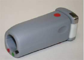
Figure 00. Hand-held Force and Torque monitor for Colonoscope (Metropolitan Gastroenterology Group, Washington, DC; Artann Labs, Ewing, NJ)
Retrieved from: (https://www-clinicalkey-com.cyber.usask.ca/#!/content/playContent/1-s2.0-S0016510714004921?returnurl=null&referrer=null)
The CFM constantly measures, records and display the applied push or pull forces and torque (clockwise and anticlockwise) applied to the insertion area of the colonoscope. Mainly CFM consists of two major parts (1) wireless handgrip assembly mounted on the colonoscope, and (2) the computer for data processing, recording and display (Sarvazyan, et al. 2004).


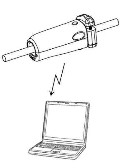
Hand Griper
Colonoscope Shaft
Wireless Data Transmitted to Computer for Display
Figure 00: Colonoscope Force Monitoring System (Sarvazyan, et al. 2011, Artann Laboratories, Inc.)
Retrieved from: (http://patentimages.storage.googleapis.com/US20110065991A1/US20110065991A1-20110317-D00000.png)
The handgrip part designed in such a way that it contains two layers of sleeves known as an internal sleeve and an external sleeve. The internal sleeve is positioned in direct contact over the shaft of the colonoscope, so that it can be released and repositioned over the shaft through a release button. The external sleeve covers over the internal sleeve and it provides an appropriate grip to the user. The force applied by the user or operator at the external sleeve will be transmitted to the internal sleeve through an engaging means, that contains engaging plates embedded between the internal and the external sleeves.
The engaging means are equipped with a set of force sensors such as strain gages, that measures the forces between the sleeves that are the forces applied by the operator to the shaft of the colonoscope. The data acquired by the sensors will then transmitted wirelessly to the computer for further processing and display.


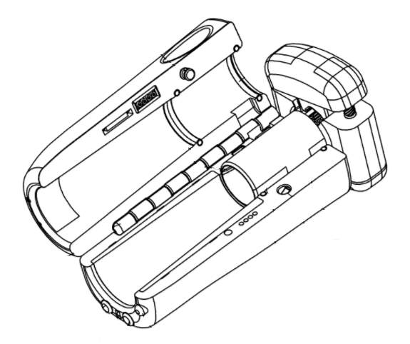
External Sleeve
Internal Sleeve
Figure 00: Internal view of CFM (Sarvazyan, et al. 2011, Artann Laboratories, Inc.)
Retrieved from: (https://www.google.com/patents/US20110065991)
Block diagram of CFM System working:
Force Sensor
Torque Sensor


External Sleeve
Data Acquisition and preprocessing
Internal Sleeve
Wireless communication
Wireless communication
Data processing and recording


Display
Flexible Force Sensor:
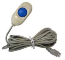
The flexible sensor is an ultra-thin and flexible printed circuit. One end of this sensor is applied to the insertion tube of the colonoscope for the purpose to collect the data of the contact force that occur between the colon tissue walls and colonoscope, which we are considering as the Friction Force. Whereas the other end of the sensor relates to the sensor handle technically known as Economical Load and Force (ELF) handle, once the sensor senses any force this handle will gather the data from the sensor, processes in into digital form and transfer it to the computer via USB connection for the display (Tekscan Inc., 2015).
The sensor is composed of two layers of substrate like polyester film, and on each layer conductive silver material is applied that is being followed by a layer of pressure/force sensitive ink. Adhesive is used to laminate the two layers of the substrate together to form the sensor. The sliver conductive material forms the conductive path that extends from the pressure/force sensing area to the other end of the sensor that connects to the ELF handle. The sensor acts as a variable resistor that changes its resistance according to the load/pressure applied on it. If the sensor is unloaded the resistance is very high, means the analog to digital convertor produces 0 Volts at output, when the force is applied the resistance decreases the output will very accordingly (Tekscan Inc., 2015).

(a)
(b)
Figure 00: (a) FlexiForce HT201 force and load sensor. (b) ELF USB handle (Tekscan, Inc., South Boston, USA)
Retrieved from: (http://ubsenthoff.de/wp/tekscan/ht201)
Block diagram of Flexible Sensor System working:

Pressure / Force sensitive ink

Conductive silver material


Data acquisition and pre-processing

USB communication


USB communication

Data processing and recording

Display
System Flow in case of Loop Formation:
By applying these force and friction measuring devices with the colonoscope, the colonoscopist will be able to identify current situation of a colonoscopy procedure. If there will be any loop problem or a self-locking mechanism occurs then the operator will be able to overcome it because real time information that acquired from CFM which is connected outside human body and flexible force sensor attached at the distal end of the scope will be send for real time display. Therefore, the operator will able to see force exerted to the tip of insertion tube and if it is not correct so he will change the orientation of the tip.
Insertion Tube
Human Body
Self-Locking


Colonoscopist
will review display (applied force and friction)
Message sends from CFM and Flexible Sensor
Orientation of scope will be changed in case of Loop


Evaluation of the Model:
The same Axiomatic Design Theory (Suh, 1998) will apply on this model which has been used in the previous section for the evaluation of the existing colonoscopy system. The proposed model has the functional requirements (FRs) that explains that during the procedure the distal end of the scope must kept away from the stick state and it also covers all the four constraint requirements (CRs) as well. Finally, the design parameter (DP) of the model depends on the push / pull of the scope in the forward direction while keeping the driving angle greater than friction angle.
|
Functional Requirements FRs |
Constraints Requirements (CRs) CR1 CR2 CR3 CR4 |
|||
| | | | | |
The further evaluation of the proposed model could be done by applying the concept presented by Dr. Zhang and his team on the function, behavior and structure model for design (Zhang, et al. 2011). The application of this theory evaluates the parameters defining the model as a good or a bad model. These parameters are as follows:
Validity: Upon receiving the information over a display panel of the force measuring devices, the operator follows the procedure as per defined over a display panel so process can be performed smoothly and validity of a system will remain as designed i.e. output will be accomplished in a perfect way.
Utility: Information occurring from CFM and flexible force sensor will be accurate and real-time on display. So, it will be depending on the colonoscopist or operator on how they perform a process. Otherwise, it will be a perfect utility to give required output.
Reliability: Process applied on a same patient multiple time after a regular interval for a same day, the results will always be obtained as same.
Comprehensiveness: Colonoscope is only required to be integrated with different companies of display panel or control unit, this is only area for the comprehensiveness. The system will be designed in such a way the integration will remain uniform whenever it combines with any other device.
Ease of use (usability): it will be a user-friendly device and its uses will be designed as easy for the use of all type of medical staff.
SIMULATION FOR APPLIED FORCE AND FRICTION FORCE DISPLAY
System Summary:
- In this simulation program, we are going to sense the force / pressure at the two places, which are considered as applied force (A.F) and friction force (F.F).
- It is also considered that, one force sensor is installed in the CFM and another installed at the distal end of the scope which will be inserted to the patient’s colon.
- For the simulation purpose the force sensor is constructed in the form of Force Sensing Resistor (FSR) and the change in force is considered as change in resistance of FSR.
- The display shows the Applied Force (A.F) in Newtons, which is basically the generated by the change in resistance by FSR 1. Similarly, the display of Friction Force (F.F) shown in the same manner produce by FSR 2.
- The system is based on the Arduino, which consist of a programmable PIC controller chip, two number of FSR (FSR 1 & FSR 2) sensors and the LCD (16 X 4), the complete system is power up by 5-volt supply achieved by LM7805 regulator IC or else.
- The value read by the sensors feed into the Arduino, where the values is processed by the processor embed by the C language program then further feed to the LCD which shows the applied and friction force on the sensors.
Required Software:
The circuit has been designed in Proteus 8 Professional and the coding of Arduino is done in C language.
Required Components:
- FSR: FSR’s are basically a resistor that changes its resistive value (in ohms Ω) depending on how much its pressed. These sensors are low cost, and easy to use but they’re very accurate. The variance level of these sensors is considered about +10%. So basically, when you use FSR’s you should only expect to get ranges of response. There are various kind of FSR available according to the application and use, which have distinct resistance variable values.
- ARDIUNO: Arduino is an open source computer hardware and software company, project, and user community that designs and manufactures single-board microcontrollers and microcontroller kits for building digital devices and interactive objects that can sense and control objects in the physical world. The project’s products are distributed as open-source hardware and software, which are licensed under the GNU Lesser General Public License (LGPL) or the GNU General Public License (GPL), permitting the manufacture of Arduino boards and software distribution by anyone. Arduino boards are available commercially in pre-assembled form, or as do-it-yourself kits.
- LCD 16 X 4: simple display with green or yellow back ground, which have 4 lines in each line only 16 characters can be shown, this LCD is readily available anywhere.
Circuit Diagram:
Applied Force


Friction Force

FSR 1 variable resistor
FSR 2 variable resistor
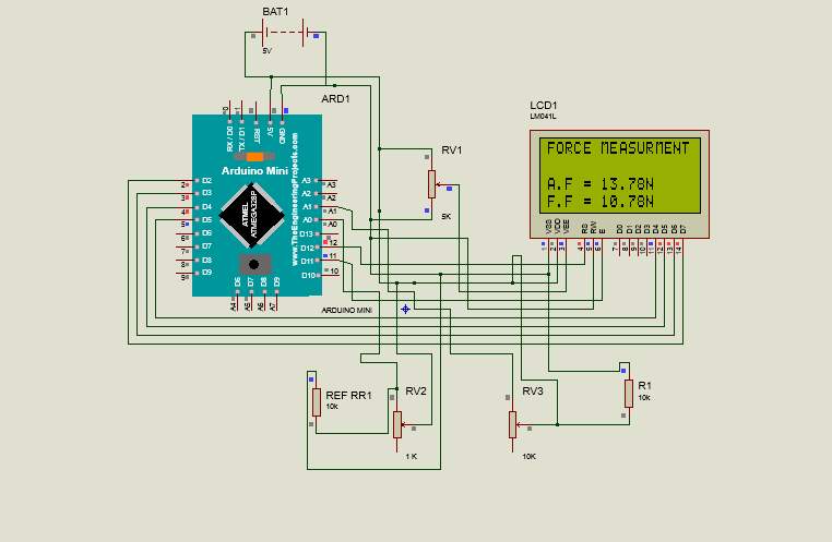
Figure 00: Circuit diagram for applied force and friction force measuring and display.
Description of Circuit Diagram:
- There are 13 digital ports defined in the PIC controller, we are using 6 digital ports out of which 4 are designated for 4-bit data transferring to LCD and 2 defined for writing and resetting the display.
- Apart from digital ports there are 4 analog ports in the PIC controller, we are using 2 ports to collecting the data from the FSRs.
- As we know the FSR is a type of transducer which convert force / pressure into resistance, so we are achieving data in the form of variable resistance but the analog port of PIC controller only accepts the data by mean of variable voltage or variable current so we used a resister in series with each FSR which are acting as voltage divider.
Steps to run the simulation program:
- First of it is required to download the complete version of PROTEUS 8 PROFESSIONAL (Proteus Design Suit 8.0) software.
- Copy the folder “Force and Friction measurement project” on the desktop. This folder must have two files named as “force2FSR” and “sketch_jul27a.ino.hex”.
- Now double click on the file “force2FSR” file. This will initialize the Proteus software as well as the circuit diagram for applied force and friction force measuring and display.
- Now double click on the IC AEMEGA328P. A new window “Edit Component” will open. In the Program File option define the path for the file “sketch_jul27a.ino.hex” and select OK.
- On the main bar of the Proteus 8 software select “Debug” and then click on “Start VSM Debugging”.
- Select again “Debug” and then click on “Run Simulation”. This will initialize the simulation program; the LCD display will start showing the different values of applied force (A.F) and friction force (F.F).
Sato K., Fujinuma S., Sakai Y., (2006), Original Article Evaluation of the looping formation and pain during insertion into the cecum in colonoscopy. Gastrointestinal Endoscopy.
Mitchell R.M., McCallion K., Gardiner K.R., Watson R.G., Collins J.S., (2002), Successful colonoscopy; completion rates and reasons for incompletion. Ulster Medical Journal.
Shah S.G., Saunders B.P., Brooker J.C., Williams C.B., (2000), Magnetic imaging of colonoscopy: an audit of looping, accuracy and ancillary maneuvers. Gastrointestinal Endoscopy.
Eickhoff A., Pickhardt P.J., Hartmann D., Riemann J.F., (2010), Colon anatomy based on CT colonography and fluoroscopy: impact on looping, straightening and ancillary manoeuvres in colonoscopy. Digestive and Liver Disease.
Park D.I., Kim H.J., Park J.H., Cho Y.K., Schn C.I., Jeon W.K., KimB.I., (2007), Factors affecting abdominal pain during colonoscopy. European Journal of Gastroenterology & Hepatology.
Moser M.A., Cheng W.B., Kanagaratnam S., Zhang W.J., (2012), Analysis of and mathematical model insight into loop formation in colonoscopy. Proceeding of Institution of Mechanical Engineers. Part H, Journal of engineering in medicine.
Dequidt J., Duriez C., Cotin S., Kerrien E., (2009), Towards interactive planning of coil embolization in brain aneurysms. Medical Image Computing and Computer-Assisted Intervention: MICCAI.
Cheng W.B., Moser M., Kanagaratnam S., Zhang W.J., (2012), Overview of upcoming advances in colonoscopy. Digestive Endoscopy: official journal of the Japan Gastroenterological Endoscopy Society.
Artann Laboratories, Colonoscopy Force Monitor. (http://www.artannlabs.com/technologies/colonoscopy-force-monitor.html).
Sarvazyan A., Korman L.Y., Tsyuryupa S., (2004), Colonoscope handgrip with force and torque monitor. US 6981945 B1, Artann Laboratories, Inc.
Tekscan, Inc. (2015), ELF & WELF 2 User Manual, (http://ubsenthoff.de/wp/tekscan).
Cite This Work
To export a reference to this article please select a referencing stye below:
Related Services
View allRelated Content
All TagsContent relating to: "Medical"
The word Medical refers to preventing or treating injuries or illnesses, relating to the study or practice of medicine. Medical care involves caring for a patient and helping them through their journey to recovery.
Related Articles
DMCA / Removal Request
If you are the original writer of this dissertation and no longer wish to have your work published on the UKDiss.com website then please:


