Data Communication in a High Security Environment: Financial Company
Info: 7221 words (29 pages) Dissertation
Published: 10th Dec 2019
Tagged: FinanceCyber Security
Data Communication in A High Security Environment
-The technology implementation in a financial company
Network topology of data centers
Protocols used in security point of view
OSPF (Open shortest path first)
Ethernet Protocol (IEEE 802.3)
Spanning Tree Protocol (STP/IEEE 802.1D)
Technologies used to implement network security
Remote Authentication Dial-In User Service (RADIUS)
Port-Base Network Access Control (802.1 X/PNAC)
IDS (Intrusion Detection System) Integration to the company
Network Intrusion Detection System (NIDS)
Host-Based Intrusion Detection System (HIDS)
IPsec (Internet Protocol Security)
ESP (Encapsulation Security Protocol)
TLS (Transport Layer Security)
Network Management and Security
VLAN (Virtual local area network/ IEEE 802.1Q)
Simple Network Management Protocol (SNMP)
Management Information Base (MIB)
HSRP (Hot Standby Router Protocol)
Disaster Recovery and Risk Assessment
Meeting Minutes and Attendance
Executive Summary
This research report is going to analyze a network which belongs to a large company in China. It is a financial company and is a merger of three companies. The company provides stocks, bonds, futures, etc. trading services to clients. It has very high-security standards for the simple reason it is a financial company. This company has more than 250 branches and 3 data centers. The network is very complex because 3 data centers and big branches divide their network into 3 levels, each level connects to different networks, for example, level 1 connects to the Internet, level 2 connects to exchanges and level 3 connect to branches. There are firewalls between each level, only a few types of traffic can go through them. The traffic must match trusted IP addresses, MAC address and certain type, for example, trade information traffic and trading traffic. There are three types of branches in this company, the branches have 3 levels of the network are type 1, which means their network structure similar to the data centers. Other two types are B and C which only have Internet access, the difference between them only bases on the number of PC, type 2 has more than 500 hundred PCs and type 3 has less than 500. They both connect to one of the data centers via VPN.
For security reason, this research report is not going to mention the name of the company, operation system version, configuration details or any sensitive information. It only focuses on the technologies that the company used and the security ideas behind its network design.
Introduction
Overview of the network
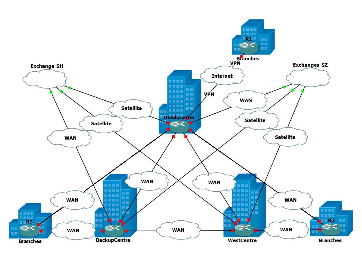
Figure 1: Overview of the network
Figure 1 is a brief diagram of the network of the company. In the middle of the diagram is the three data centers: Headquarter, Backup Center and West Center. They all have two links to exchanges and they connect to each other via WAN. In addition to all data centers and branches have their own two Internet connections which are provided by different ISP, data center has dozens of branches connected through WAN. For type 1 branches, which have two WAN connections, connect to 2 data centers. For other types of branches, they only have Internet access and connect one of data center via VPN. Also, data centers connect to exchanges through satellite or WAN, depending on the distance between data center and exchange.
Network topology of data centers
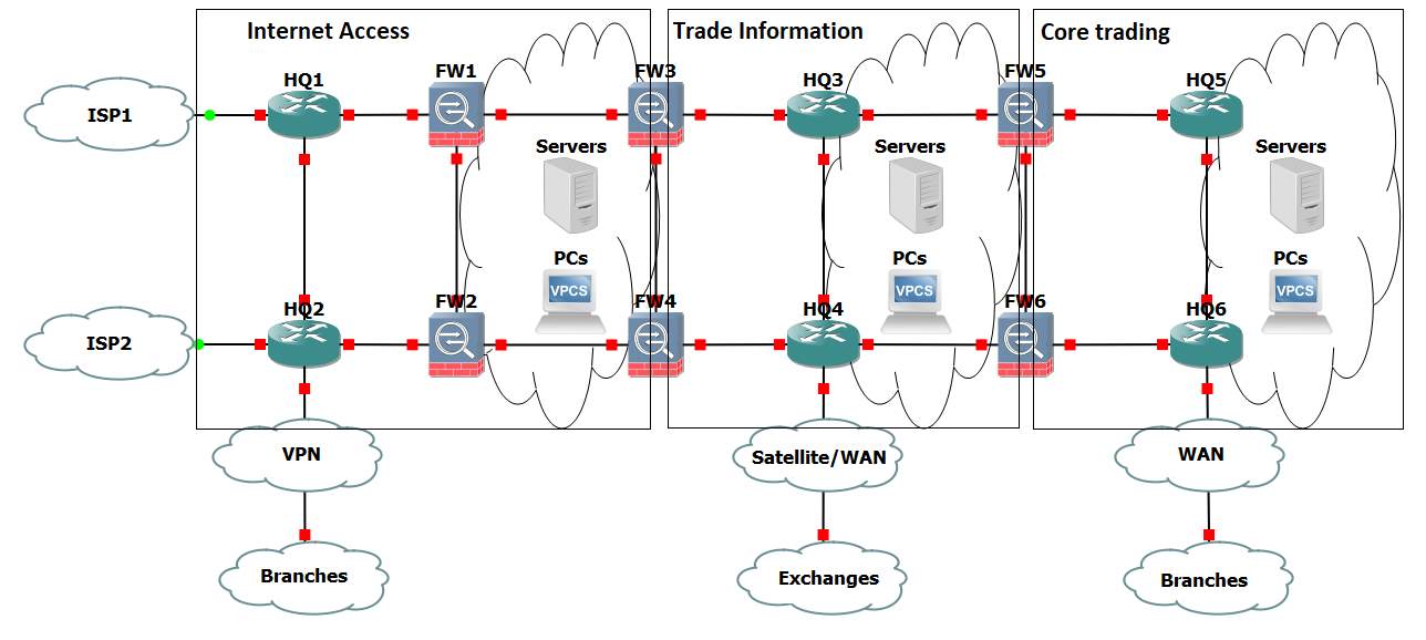
Figure 2: Network topology of data centers
As figure 2 has shown, the network is divided into three layers by firewalls, each layer does specific tasks. The name of Internet access is straightforward, this part of the network provides Internet access and connection to type 2 and type 3 branches via site-to-site VPN. Web servers are located in this part of the network.
The layer in the middle is so-called Trade information which receives real-time quotations, processes data, and indexes. This part of the network cannot access the Internet. The firewalls between trade information and Internet access only allow information from exchanges, trading information, system information and some peripheral information from trusted devices go through them. Also, the firewalls inspect all traffic go through them and report suspicious traffic to security information and event management server.
The network behind 3 layers of firewalls is the Core trading part of the network. This is the part where transactions happen and apply the most restrictive security standard. The access rules are one step further than trade information. The firewalls only allow trading information and system message go through them. In addition to client information, this is where transaction history and trading history stored. Also, this part of network connects to bank system.
Network topology of branches
There are three types of branches. Basically, the largest branches are type 1, which the network is similar to the data center, 3 layers of the network, connections to data centers via WAN, etc. The network of type 2 and type 3 branches is much simpler than type 1, they only have Internet access part and connect to data centers via site-to-site VPN. The difference between type 2 and type 3 is the size. Type 2 has more than 500 PCs and type 3 has less than 500.
Design concept of the network
As figure 1 and figure 2 has demonstrated, the priority of the design of the network is security. Redundancies are provided in every part of the network. Although most data centralized in Headquarter data center, a backup center is built in a different city. All data centers and branches have two Internet links from different ISP and redundancy devices, such as routers, firewalls, core switches and servers. For data centers, each connection to exchanges is able to receive trade information from both exchanges, so those two links can backup each other. The same happens in the Core trading part, two links to other data centers provide full mesh connection between data centers. Such design ensures that single failure in anywhere of the network cannot affect the entire network. Three-layer network architecture design fits the different security requirements for various services while stop threats from outside.
In addition to the information security measures mentioned above, the company also applies robust redundancy power supply and security management rules. For all data centers and type 1 branches, where trading traffic goes through them, have been equipped two UPSs which backup each other to support whole server room running in maximum power more than four hours. Further, diesel generators have been installed in case of long hours of power outage.
Just like the measures about information security and power supply security, the rules of access to the server room is restrictive.
Protocols used in security point of view
OSPF (Open shortest path first)
OSPF is an internal routing protocol that was initially designed to replace RIP and other IGP (Interior Gateway protocol) like IGP. Unlike previously popular standards, OSPF does not use bellman-ford distance vector algorithm but instead uses link state routing (Dijkstra algorithm) to dynamically base decisions on more than just hop count. OSPF uses a cost metric to calculate speed and impact of packets traveling over certain paths using the formulae “Interface Cost = Reference bandwidth/interface bandwidth”. By using total bandwidth and real-world bandwidth, this allows OSPF to gauge the speeds across the network and choosing the shortest/best path. OSPF also partners this cost information with a network topology map using Link State Advertisements (LSA). LSA messages are passed to adjacent routers and list routes along with cost metrics, building up an LSA database in which the topology of the network is created. Each router will have an identical network map but calculate its own cost based on the information it is sent (What is Open Shortest Path First (OSPF)?, 2017). To share LSA with other routers, OSPF will flood the local network to spread data using a multicast network address. A separate protocol solution called protocol independent multicast (PIM) takes care of the multicast traffic. OSPF can use flooding because it is an IGP and flooding will only spread within its own network. If a router using OSPF is a part of two networks, this router must keep two databases and make sure LSA don’t across into the other network. This router would be classed as an area border router (ABR). Since LSA are smaller in size compared to other IGP updates, link failures can be detected easily allowing the network to quickly update and converge.
When it comes to security, OSPF can offer network admins the ability to add authentication into their network (using IPv4, IPv6 will be explained later). OSPF can be used three ways, no authentication, plain text and MD5 hashing. The first option is to have no authentication, OSPF by default is set up with no authentication. Most small networks may not need this added authentication as it adds complexity and higher up layers already encrypt and protect user data. Plain text, adds an extra layer of security by using a key to authenticate other router updates. This is generally not used as it does add authentication but also makes it almost useless because keys are share in plain text. The last option is using MD5 to hash a key. Before spending an update, the spending router hashes specific identifying information and LSA into a fixed length result. The receiving router then uses an MD5 hashing function to match and authenticate the sending router. A common key is shared between routers and is used to help hash information. By using MD5, OPSF can reduce the likely-hood of spoofing attacks on a network by having all routers authenticate each other.
The OSPF protocol also has some quirks and disadvantages, the two main disadvantages are, same cost metrics on interfaces higher than 100Mbps and the lack of Quality of service. The first point, OSPF assigns all interfaces over 100Mbps with a value of one, so 1Gbps 10Gbps and 100Gbps are all the same speed and cost the same amount as a 100Mbps line. This can lead to traffic (if not paired with other protocols) to choose lower speed routes compared to the higher bandwidth routes (How to configure OSPF cost, 2017). This is easily solved with either auto calculation of routes or manually change the cost metrics of each router. Both do require admin setup. Problems that networks may face with this quirk is when adding new high-speed equipment, routers cost need to change to reflect the new costing values.
The second point is the lack of Quality of service. Like most other Interior Gateway Protocols, OSPF doesn’t have its own QoS and therefore relies on other protocols like Multiprotocol label switching (MPSL) to calculate QoS over the network. This is due to OSPF using static information on routes which must be configured manually. Research into IGP with QoS is still underway researchers but currently, there is no native solution.
When it comes to implantation, The company uses OPSF in throughout the whole internal network. This is paired alongside route map (as mentioned in this report), static routes and default routes. The information around the exact details of OSPF are secret and have not been disclosed. But based on details given, we can assume that the network uses OSPF because it’s the de facto standard for internal network routing. Since the network started off as three separate networks before merging them (after the three company’s merged into The company), this might give us an idea of why they use OSPF. OPSF is an open standard designed by IETF and was designed to work across many routers using IPv4[1]. It works well with using different vendors and models and is mostly used to enterprise networking due to it working on layer 3 and routing the internet protocol standard (IP) natively. Compared to other IGP’s, like EIGRP and IS-IS, OSPF has clear advantages over its competitors. EIGRP is an IGP that is powerful but is Cisco proprietary and only in 2013 was converted to an open standard (published 2016) (RFC7868, 2016). The company uses Cisco and Huawei products currently in their network, EIGRP would not be able to be used in this network due to the incompatibility. IS-IS is also another IGP that could have been used in the network, but due to its lack of market share in enterprise networking and because it was not designed natively for layer 3 routing, IS-IS would have been hard to implement in The company’s network. IS-IS is de facto standard for ISP networks in the network backbone due to its non-reliance on the IP standard (Goraiski, 2005).
Route Map
The route map is classed under Policy-based Routing and is used in a network to filter routes, limit reachability and enforce network policy. The route map is usually compared to an Access Control List due to its same fundamentally design and that it shares some common features. Route map overall can be a more flexible tool when managing networks due to the way it handles traffic filtering when it comes to rules and when it comes to redistributing networks.
Filtering
Comparing it to ACL, route map uses a similar listed based approach for policy clauses. A clause in route map referrers to a rule or statement, like what you would find in a firewall or an ACL. Both route map and ACL use an ordered list to filter traffic, when certain traffic matches a policy clause, that action corresponding to the clause is done. E.g. the first clause might allow all TCP/IP traffic from network 192.1.68.1.0 to access network 192.168.2.0, so any traffic from the 192.168.1.0 will match with this clause carry out a corresponding action. The lists clauses are also ordered, rules at the top of the list are checked first and filter down to the bottom. Cisco recommends numbering clauses in lots a ten (E.g. 10,20,30) this allows more clauses to be added later with little impact, this is considered to be best practice (Route-Maps for IP Routing Protocol Redistribution Configuration, 2005). Normally with an ACL, an implicit deny rule is at the bottom of the list, so any traffic not mentioned in the list will automatically be denied. With Route map, no implicit deny is mentioned and the traffic will be dealt with based on the application. Route map also uses another set of clauses to help filter traffic, these are the ‘match’ and ‘set’ values. These values allow route map to identify and ‘match’ traffic and can ‘set’ new routing information, these values are used when traffic is traveling to a different network that uses a different protocol. This is called route redistributing (RR) (Le, 2013).
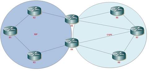
Figure 2: Route redistributing
Redistribution
The route map is usually used in networks to provide redistribution of routes for OSPF, RIP or EIGRP. In simple terms, going from one network that uses RIP to another that uses OSPF, route map redistributes the route and can change routing information so links can be compatible with other links. A common use case for route maps is when companies merge and the networks need to be linked. In the picture below, two networks are connected, one side is using RIP while the other is using OSPF. One method to glue the networks together would be to use the route map to redistribute these protocols so that if router one (R1) wants to talk to router five (R5) it can do with little to no problems. The route map can do this because it can change routing information of packets and translate network cost from hop counts used in the RIP to OSPF cost.
In the company, the route map is used with OSPF to setup and help with static routes and default routes (route map needs to setup OSPF default route). OPSF, static route and default are the backbone for internal routing with route map support the structure. The other use for route map is for security. In the company, branch routers are not allowed to be able to see or have access to other branches routing information. Allowing this would allow for extra risk as routers would be able to possibly map out the company’s network and increase the companies attack surface. The route map is used to reduce possible attack surface and network knowledge by filtering traffic and telling data center routers not to advertise branch routing information to other branches.
Ethernet Protocol (IEEE 802.3)
Ethernet in one of the main protocol which controls data transmitted over the LAN (Local Area Network). network and allow a computer to connect to another computer within the same network segment in Local Area network. Ethernet protocol most commonly using in LAN and WAN network. In order to connect to the Local Area network using by Ethernet protocol, a user needs to have some Ethernet hardware components in order to work Ethernet. Such as Ethernet adapter, Ethernet cable, Ethernet router and so on.
Ethernet is work on the link layer protocol in TCP/IP models which is connect with both layers, physical and data link layer (layer 1 and layer 2) on the OSI network model. Ethernet has two transmission unit call frame and packet. Ethernet has a Frame which spites the data into the multiple pieces call Ethernet frame and send these data transmissions one by one. Ethernet frame does not only include the just about the payload of the transmit data. It’s also addressing and identifying the information about the targeting network device MAC address “Media access control”. MAC address is assigned to hardware vendors and each network device get unique MAC address. This MAC address using an Ethernet protocol to transmit the data over the local area network.
When it comes to the speeds of the Ethernet network connection, its capable of transmitting the data fast and consistent rate up to (100mbps). Ethernet able to handle about 10,000,00 bit per second which can use in any type of computer. Ethernet has three main connection type such as Ethernet, Fast Ethernet and Gigabit Ethernet (IEEE 802.3u /IEEE 802.3z)
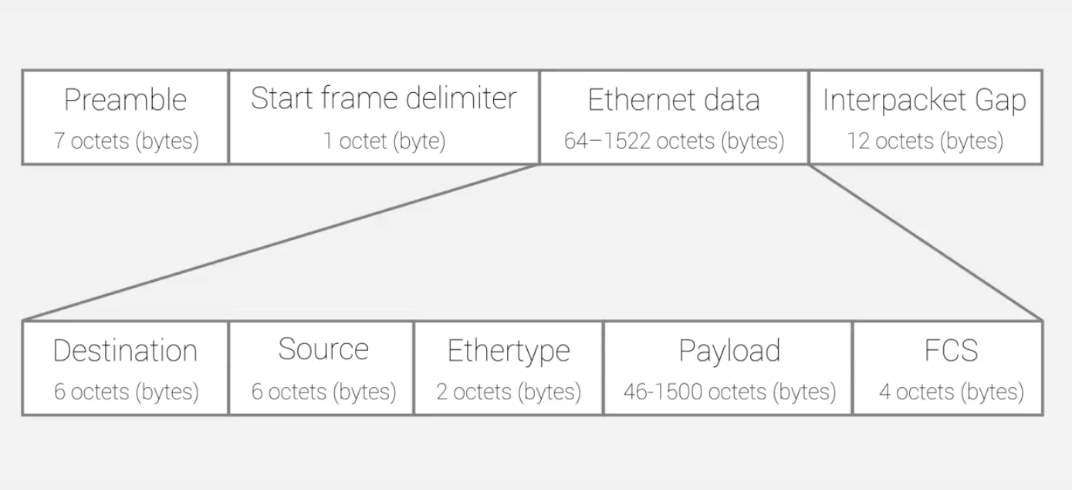
Figure 3: The format of Ethernet
As mention above Ethernet frame is split up data into the multiple data packets on the Ethernet and each frame header contain the details about targeting address and source MAC address. Before transmitting any packet over the network, devices need to get preamble out call start frame delimiter (SFD) which is initial sequence bits on the Ethernet frame. Once done with the preamble and frame delimiter, the device has to send the destination MAC address and followed by own MAC address.
If the user doesn’t know about the MAC address on targeting computer or wants to transmit data to every machine over the network, then has to use special broadcast MAC of all “F” which enable another machine to advertise services such as file shares and print availability with the other devices over the same network. Ethernet frame has another filed called (ether type) which can be used for deferent types of purposes. For example, if the number in this field is 1500 or lower it that indicate about the total length of the Ethernet frame. Although nowadays its typically use to indicate contents of the frame other than the length of the frame. After a check with this all information, devices can finally send the data over the network using Ethernet.
Spanning Tree Protocol (STP/IEEE 802.1D)
STP is a widely implemented protocol in networks which is in layer 2 (data link layer) network protocol using MAC address as running on the switches and bridges that help to prevent the condition of loop-free in the network. Normally when setting up the network in switches, it will take extremely long time for the port to initialize. Therefore, this spanning tree protocol basically necessary for switches to process the coexist. Spanning tree protocol has two major functions that allow switches environment to prevent switching loops. Switching loops happened when data packet gets into the loop if there more than one way to get from one path to another and its cycle it with in that loop which eliminate that process. The second function that has in spanning tree protocol is provided backup link as there have many links connect with one switch to another which allows when once link down or get failure its automatically start and open another link that links to provide a stable connection in between switches STP has following few main function such as:
- Prevent the issues happened by loops on network
- Planning and save redundant path (backup) due to some network failure
- Helping to find the shortest path to switch
Furthermore, spanning tree protocol implementing three deferent port role function such as root port designated port and block the port. The Root port is the closest port to the root switch which is all ways open and responsible for carrying the data packet over the network from this segment to the root switch, choosing closets path to get the root.
Talking about to designated port, on each segment there would be only one designated port which is facing to root port and it’s all ways open and responsible for forwarding the packet from root switch. The last one is Block port which does not send or receive any packet
STP elects a root switch and it would become the focal point of the network to determine which port goes into forwarding mode and which port goes into blocking mode. In switching environment, need to deal with multiple VLANs. Each VLAN in a network represents a separate broadcast domain of a network. Therefore each of these VLANs required its own root switch. Roots for all VLANs may retain in a single root switch and configure a root switch for each and every VLAN is very important.
There are several extended versions of STP. Some of those can be described as below.
PVST (Per-VLAN Spanning Tree)
In an environment where multiple VLANs exists, PVST can be used to allocate separate path for each VLAN. The extended version of PVST is PVST+.
MSTP (Multiple Spanning Tree Protocol)
This creates a separate spanning tree for each VLAN group and block all possible alternative paths but keeping one path open.
VTP (Virtual Trunk Protocol)
VLAN trunk protocol is one of the protocols which can be found in Cisco categorize series product switches that allows to form and maintain VLANs for a large type of network with interconnected switches and managed consistency over the network and reduces administration on a switched network. That means all the switches in the network use VPT (Virtual Trunk Protocol) to talk within the same network about VLAN configuration. There have 3 deferent versions of VPT such as version 1, version 2(both are slightly similar to each other) and the support for taken ring VPT V2. Virtual LAN distributes via all over the switches in the domain once user configures new virtual local area network on VTP server. This help to reduces of repeating the configurations same virtual LAN in everywhere which synchronize VLAN information.
Furthermore, discuss the value of the VPT. For example, if the company needs to create VLAN in 100 of switches without configuring the VPT, then the user has to manually set up the VLAN one by one and then it will take an amount of time for finish the configuration by manually which will be the result of wasting time. Using this VPT protocol allow the user to configure and create only one Virtual LAN in the switch which propagates the information with other switches result of creating the VLAN with other switches. on the other hand, in case of user want to delete the VLAN then the user can do the same thing likewise delete the one VLAN which will automatically delete of the VLAN what user want to delete inside the same virtual truck Protocol domain.
As mentioned above VTP help for user to manage the addition, renaming and deleting of the virtual local area network (VLAN) from the central point without manually configuring our set up the VLAN.
Technologies used to implement network security
Remote Authentication Dial-In User Service (RADIUS)
RADIUS is an application layer protocol which utilizes TCP / UDP as transport. RADIUS provides centralized Authorization, Authentication and Accounting (AAA) for network access requests. RADIUS work as Client / Server according to the implementation requirements (wikipedia, RADIUS, 2017).
RADIUS was originally developed by Livingston Enterprises, Inc. in 1991 as an AA (Accounting and Authorization Protocol) and later standardized by Internet Engineering Task Force (IETF). RADIUS server can be either run in Linux / Unix Servers or in Microsoft Server as a background process. The latest implementation of RADIUS in Microsoft 2016 is called Network Policy Server where it allows to configure RADIUS as RADIUS server, RADIUS proxy, and RADIUS Accounting.
RADIUS provide access authentication by using either Kerberos or Pre-Shared Key (PSK) authentication methods where the keys are protected with 802.1X authentication methods such as Extendible Authentication Protocol (EAP/EAPOL) and IPSec while wireless communication is protected by WPA2 with AES encryptions. Moreover, the shared key between RADIUS Client and the Server is never communicated over the network.
RADIUS is used by ISPs and Enterprises to manage access requests either to internal wired and wireless networks or to external networks (ex: Internet). These access requests are generated by wired and wireless networking equipment and end devices such as wireless access points, Network Switches, Servers (VPN and other), client PCs/ Laptops/ Tablets/ Mobile Phones etc. (Roland, 2004).
In the client-server model, NAS devices pass the user information to the RADIUS server for authentication. In return, RADIUS authenticates and authorize the client credential and pass that access token to the NAS device and NAS device then relay the access token to the end- device.
Network Policy Server (NPS)
NPS is the Microsoft version of RADIUS server and RADIUS Proxy. This is the successor of Internet Authentication Service (IAS). (jamesmci, 2017)
NPS provides the facility to configure and enforce enterprise-wide Network Access Policies to authenticate and authorize connection requests.
Moreover, NPS can be configured as a RADIUS Proxy to forward connection requests to another NPS server or to a RADIUS server to provide load balancing and to authenticate and authorize connection requests from the relevant domain (microsoft, 2008).
RADIUS server can be configured in 3 different ways as follows,
- RADIUS Server
NPS can be configured as a RADIUS server to perform AAA (Authentication, Authorization, and Accounting). Once configure the NPS as a RADIUS server, VPN servers, wireless APs, and NAS servers can be configured as RADIUS clients in NPS. Moreover, NPS policies and RADIUS accounting can be configured to authorize connection requests and to log the accounting information into the local HDD or to a SQL server DB respectively (networkradius, 2014).
Windows Server 2016 Standard Edition offers a facility to configure 50 radius clients while 2016 Datacenter Edition supports an unlimited number of RADIUS clients.
RADIUS authenticates dial-up remote access, VPN, Wireless and authenticating switches. NPS can be used in connection with RAS (Remote Access Service).
NPS uses AD DS or Local (SAM) for authenticating client requests. Mostly, AD DS is used and is helping single sign-on capability. RADIUS cashes authorized access tokens and offers seamless authentication for roaming clients.
RADIUS server can be configured to provide network equipment health check and MAC filtering as well.
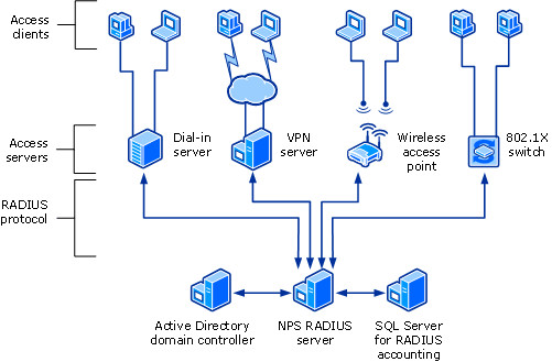
Figure 6: NPS RADIUS Server Communication
RADIUS Proxy
Once configured the NPS as a RADIUS Proxy, NPS policies can be configured to forward connection requests to other RADIUS servers. Furthermore, NPS can be configured to forward accounting information to be logged in one or more other servers or computers in another RADIUS server group. Once configured, RADIUS works as a central routing and switching point where all RADIUS access and accounting information flow through and it also cashes the messages which are forwarded.
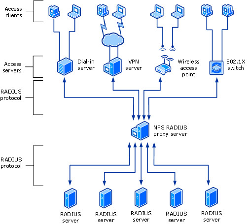
Figure 7: NPS RADIUS Proxy Communication
RADIUS Accounting
NPS logging can be used to log whatever the events needed to appear in event viewer and what are the other information which those events should be included. Moreover, it can be configured to save accounting information on the local computer or a SQL database which is located locally or remotely in another RADIUS server group.
This specific RADIUS server (Open RADIUS) has been kept inside the network on top of Linux based operating system to authenticate users based on Kerberos authentication. These RADIUS servers secured the network with port-based authentication and each and every time user change the working network port, required to reauthenticate with the radius server. This mechanism is typically implemented because this particular organization did not use any wireless communication mechanism due to high-security requirement. When a user is required to connect to the network, they were navigated to a web page where they have to put their credentials in order to get authenticated to access the network.
Port-Base Network Access Control (802.1 X/PNAC)
In current time there has some challenge to maintain the security in port and switches in the network. Basically, when somebody plugs their cable into switches interface, it will automatically have assigned access to the local area network, even its unauthorized device which will extremely effect privacy of the network. In order to prevent from that kind of situation 802.1 x, port-based authentication provides a safe environment to every port which asks authenticate first use by user credentials before access over the network through switch port.
To run this 802.1 X user, need to download some special software which can be download from the Cisco website. Once user downloads and install that software which will ask to authenticate the user name/ password to grant permission for access to the network. Once supplicant enter their username/password that authenticator which is switch will take that supplicant credential and pass it along to authentication server database to match with that credentials. Finally, the server sends back to the response to the authenticator to whether provide access permission or deny permission.
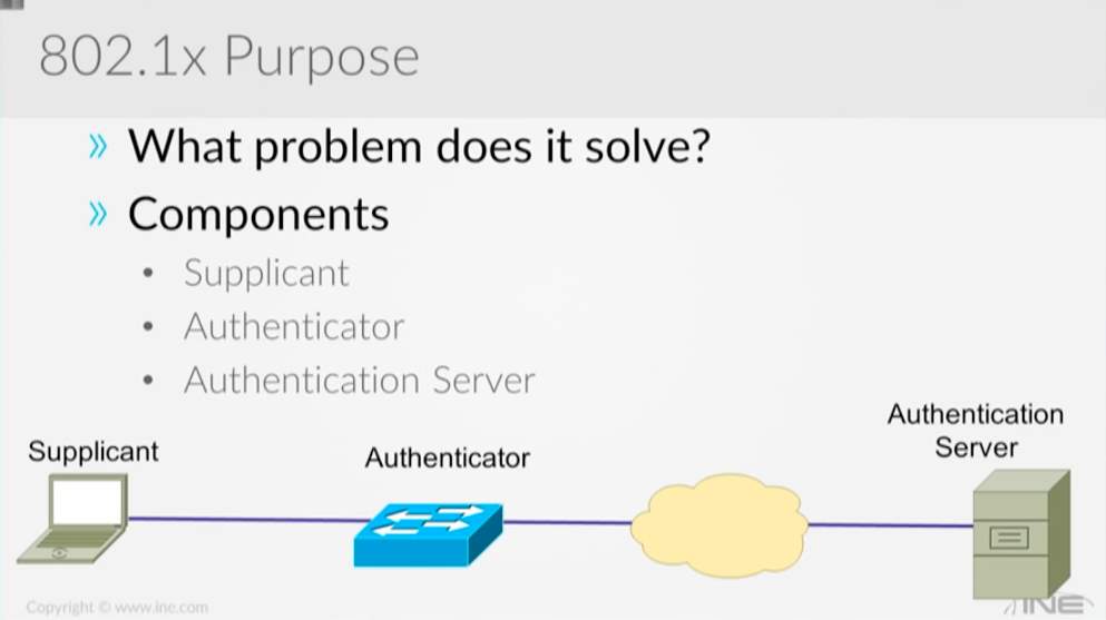
Figure 5: Components of 802.1x
Main protocol use in 802.1 X is extendable authentication protocol (EAPOL) and Radius. The Ethernet Frame going between supplicant and authenticator (switch) which is carrying EEP instead of carrying an IP address to the authenticator by the supplicant. This is the reason why supplicant required to have special software to create the body of the frame used by EEP. That same process goes through the authenticator (switch) to authentication server but that credentials of the user details which copy into radius packet from the authenticator to authentication server.
Firewalls
This company used Huawei as the main firewall brand. They have used several versions of the firewalls in branches and in its Data Center as below
- Data center firewalls: Huawei – USG6670/6660/6630/6620
- Branch firewalls: Huawei USG6320/6330/6350/6360/6370/6620
- Branch Firewalls: Sangfor
These firewalls placed in strategic points of the network according to the level of security required for each section of the network infrastructure, Firewall policies were also configured differently according to the requirement of the security level of each segment of the network.
NOTE:
Protocols which were opened through these firewalls according to the specific security requirement of each level were highly confidential and therefore we couldn’t access that information.
IDS (Intrusion Detection System) Integration to the company
Intrusion Detection Systems or IDS is a hardware and software solution configured to identify, analyses and alert network system admins to potentially harmful or suspicious traffic. This is system is one of many different elements to a network’s defenses. Other similar systems are intrusion prevention systems (IPS), traditional firewalls and newer defense systems like Unified threat management. All of these systems work in very similar ways to protect a network but execute their processes in different ways and focus are certain areas of network defenses. Intrusion detection systems focus on creating visibility for network admins and to alert them on any abnormal traffic on the network. It doesn’t stop traffic the same way a firewall or a IPS would, but instead monitors all traffic on the network. Firewalls and IPS systems are heavily focused on external traffic coming into the network and don’t (or do very little) monitoring once pass these systems. An IDS will instead monitor network traffic looking for security policy violations, infections on internal systems, keep track on certain data leaving the network (information leakage), check for security setup errors and for unauthorized clients. An IDS will usually work in tandem with an inbuilt or standalone security information and event management system (SIEM) to help log traffic and alerts. This provides an interface for the network admins to monitor network activity.
With more and more businesses and clients switching to cloud-based computing and bring-your-own-device (BYOD) like the smart phone, the potential for virus and malware getting into a network increases dramatically due to the now increased attack surface. By using an IDS, network admins can keep tabs on network traffic and be automatically updated if abnormal traffic is picked up. This is a proactive approach to security and can potentially identify attacks on the network before they begin. A good example is the enumeration stage of a cyber-attack, hackers will be prodding the network for information regarding the structure and security policies. An IDS will be able to track and alert possible attempts to gain information or access to the network. Network admins can then monitor and track attackers allowing them to understand what the attackers are trying to get hold of, building a better knowledge of who the attackers are and how to stop them. Using a traditional system like a firewall, traffic will be allowed or denied based on setup rules, if enumeration traffic can pass through the firewall without detection, network admins are not aware and cannot prevent or be ready for an attack.
Most enterprise networks these days use devices that include one or more of the aforementioned systems. Systems from Checkpoint, Huawei and Cisco will have all these systems integrated into one device allowing for streamlined and powerful security appliances, sometimes referred to as Unified threat management (UTM) (Rouse, Unified threat management , 2014). This UTM is more powerful than many individual devices due to two parts, one is information sharing and the second is being able to virtualize the workload. By using this approach, each sub-system can share information about threats and become smarter and have a larger context. Virtualization helps by being able to share the load between virtual firewalls and increase throughput and performance. This allows some firewalls to have more than 1000 virtualized firewalls running at one time. The company currently uses security appliances from Huawei in both their data centers and in the branches. The data centers use the Secospace USG6600 series while the branches use the smaller throughput models in the same series. By having the same series of security appliances, network admins can use similar settings across the company and can focus on the correct configuration for the network. This approach adds simplicity, one of the 5 steps of defense (Sarrafpour, 2017), but it also adds a disadvantage of limiting diversity in the network. Diversity in network equipment is a good way to protect a network against possible bugs in security appliances and adds another hurdle for attackers trying to learn how to circumvent network security.
The company has set up their network into 3 parts (details of topology are covered in previous sections) using these devices to the wall in each area. Important information in this model is kept closer to the middle of the network, where traffic must pass through 3 firewalls all with different rules and setup. They also have no wireless access to the network and don’t allow BYOD for employs, this reduces attack surface and monitor network traffic without the added noise and risk that BYOD brings.
IDS can be a Hardware Device or a Software Application which monitors the network traffic or traffic inside a Host Computer for policy violations or malicious activity. Detected violations are directly reported to the administrator or recorded in centralized Security Information and Event Management System (SIEM) where SIEM uses Alarm Filtering techniques to distinguish malicious activity from false alarms. There are IDS which can respond to detected intrusions. Those are called as Intrusion Prevention Systems (wikipedia, Intrusion_detection_system, 2017).
When comparing IDS with a general firewall, it can be said that both are IT security appliances, however, while firewall filters network traffic to prevent intrusion, IDS examine network traffic from inside and outside the network signature or anomaly detection and alert administrator or maybe disconnect the network link. IDS which takes actions according to the detections are called Intrusions prevention systems.
IDS can be classified into two distinct types considering where it operates as follows,
Cite This Work
To export a reference to this article please select a referencing stye below:
Related Services
View all


Related Content
All TagsContent relating to: "Cyber Security"
Cyber security refers to technologies and practices undertaken to protect electronics systems and devices including computers, networks, smartphones, and the data they hold, from malicious damage, theft or exploitation.
Related Articles

DMCA / Removal Request
If you are the original writer of this dissertation and no longer wish to have your work published on the UKDiss.com website then please: