Setting up of Educational Wind Tunnel and Printing 3d Test Models
Info: 6152 words (25 pages) Dissertation
Published: 10th Dec 2019
Tagged: EngineeringPhysics
SETTING UP OF EDUCATIONAL WIND TUNNEL AND PRINTING 3D TEST MODELS IN UNSW: Mid-Year Progress Report
Nelson W. Taisheng[1]
UNSW Australia School of Engineering (Aerospace)
Wind Tunnels are used to conduct research on flow field on aerodynamic models and the study of flow phenomena. As full-size wind tunnels can be costly and bulky, the Educational Wind Tunnel (EWT) presents itself as an alternative for budget-conscious users, with options that allow for full customizations to meet the customers’ requirements. It is to be set-up at the University of New South Wales, Sydney, as an educational tool. In today’s world, rapidly advancing technology drives product innovations to change the way of producing wind tunnel test models. This paper studies the future 3D methods of manufacturing of a test model and identifies the value of a EWT in comparison with a traditional wind tunnel.
Nomenclature
AM = Additive Manufacturing
CNC = Computer Numerical Control
EWT = Educational Wind Tunnel
FDM = Fused Deposition Modeling
LSWT = Low-Speed Wind Tunnel
MJM = Multi Jet Modeling
Re = Reynold’s number
RWT = Research Wind Tunnel
SLA = Stereolithography
SLS = Selective Laster Sintering
T
1) Introduction
ypically, a wind tunnel plays a key role in understanding the physical characteristics of, and teaching the essential fundamentals of, aerodynamic designs applied and the aerodynamic design of the aircraft. Institutions of teaching and learning, such as Colleges and Universities, use the Educational Wind Tunnel (EWT) to facilitate teaching as well as experimental and theoretical research. Exposure to the EWT greatly enhances students’ experiences by helping them to understand advanced fluid mechanics, fluid dynamics, propulsion and combustion problems through experiments. In most institutions, the introductory course in fluid mechanics is accompanied by a laboratory course. While institutional philosophies and orientations vary around the world, the end-goal of each laboratory is similar in that they seek to strengthen students’ understanding of fluid mechanics using a variety of laboratory exercises (Feisel & Rosa, 2005).
- TYPES AND CLASSIFICATIONS OF WIND TUNNEL
There are several types of wind tunnels and several ways to classify them. Wind Tunnels are intended for specific speed regime and purpose. There are two basic types of wind tunnels: Open-circuit wind tunnels (i.e. open at both ends), and Closed-circuit wind tunnels (i.e. connected to the inlet to allow the same air to circulate in the system in a regulated way). Other types of wind tunnels include Aerodynamic wind tunnels, Environment wind tunnels, and Low turbulence level wind tunnels.
Wind Tunnels are classified based on the velocity of flow in its test section. They are classified as Subsonic, Transonic, Supersonic and Hypersonic. A complete review on the types and classifications are presented in Section 2.3 of the literature review. This paper will mainly focus on the subsonic Open-Circuit Low-Speed Wind Tunnel (LSWT).
1.2 Description of the Aerolab’s Educational Wind Tunnel
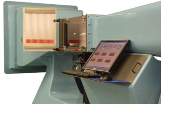
An example of an open-circuit LSWT is the Aerolab’s Educational Wind Tunnel (EWT). It is founded in 1947 by Prof. A. Wiley Sherwood, and has an air-flow slower than 100m/s (Table 1), which satisfies the incompressible flow condition. EWTs possess qualities of adaptability and flexibility which are important to today’s rapid-changing, technology-centered world. While aerodynamic flow principles have not changed, equipment and tools used to understand them has changed greatly. The Aerolab’s EWT is described as an Eiffel, or Open-circuit, with 0.3 x 0.3 x 0.61m test section. It has a top speed of 65m/s with near-infinite adjustability.
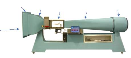
Figure 1. Aerolab’s Educational Wind Tunnel
- 3D-Printing background
Being an additive process, 3D models print at affordable prices. Contrastingly, Computer Numerical Control (CNC) machining, a subtractive process, take weeks or months to manufacture and costs tens or even thousands of dollars (Barlow, Rae, Pope et al., 1999). Since its introduction in the late 1980s, 3D printing technologies have grown tremendously in recent years. Fast-forward to 2007, the market saw its first system from 3D Systems for under $10,000 (3DPI, 2016). Due to its unfavourable price, the systems did not hit off until early-2009, when the first commercially available 3D printer was made available. From 2012, significant advances with applicability and capabilities at an industrial level contributed to a dramatic increase in awareness and demand across the market through the media and social networks. At present, a generic 3D-printer with decent specifications could be purchased at approximately $500 (Grieser, 2015).
- Materials and Methods Used
The aim of this paper was to evaluate the effectiveness of common Additive Manufacturing (AM), a term describing a set of technologies that create 3D printing objects for wind tunnel’s aerodynamic study. A traditional method of CNC machining needs four to five wind tunnel models to sufficiently test the model’s aerodynamics of a new airframe (Aghanajafi & Daneshmand, 2010). CNC machine takes a block of compact material, such as wood or aluminum, and removes unwanted parts by rotating a sharp cutter or tool around it. It is usually programmed by a Computer Aided Design (CAD) software and subsequently converted into a format readable by the printer. 3D modeling, also constructed from CAD, builds from scratch where successive layers of material are placed together in a controlled way to achieve its desired shape. Shun & Ahmed (2012) studies showed that wind tunnel testing using modern 3D printed models which contained complex details and results, were accurate and reliable. This allow for time and cost efficiency in research and manufacturing.
2) Literature Review
The first part of this literature review will be focusing on low-speed wind tunnels (LSWT); specifically examining two types of tunnels under this category with different purposes: The Educational Wind Tunnel (EWT) and the Research Wind Tunnel (RWT). The two LSWTs will be compared, to identify advantages, disadvantages, and cost. This thus provides rationale for my thesis project – where an EWT will be setup in UNSW to provide educators teaching tools to demonstrate experiments with ease and students with hand-on experiences.
The second part of this literature review will be built upon the earlier introduction to CNC and AM techniques, to identify differences and limitations between the two, and to elaborate the reason behind the rise in 3D printing – its low cost, simplicity and fast batch printing. An overview of three different 3D printing techniques (i.e. Fused Deposition Modeling (FDM) technology, Multi Jet Modeling (MJM) and Selective Laster Sintering (SLS)) will be examined.
2.1 BACKGROUND OF WIND TUNNELS
In the past, wind tunnels were extremely versatile tools that helped in understanding and studying various structures which have evolved into today’s technology. Earlier wind tunnels were purposefully used to study aircrafts in free flight. Most common aerodynamic experimental problems refer to the Direct Approach – the study of a body moving in a stationary medium, whilst Inverse Approach is the study of flow around a stationary body in the wind tunnel. Fluid mechanics laws are similar in Direct and Inverse approaches, where tunnel boundaries are neglected and dynamic conditions are strictly reversed (Martinez et al., 2016). In Wind Engineering, wind tunnel experiments were conducted to understand the forces of wind effects and to specify the required strength of such buildings. Furthermore, wind tunnel experiments and testing are also useful in the design of automobiles, where manufacturers find ways to increase vehicular efficiency.
2.2 Classifications of Wind Tunnels
Wind tunnels can be classified using three different category of classification criteria.
2.2.1 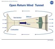 Category 1 Classification – Open vs Closed-Circuit Wind Tunnels
 Based on shapes, wind tunnels are classified as Open-circuit wind tunnels (Figure 2) and Closed-circuit wind tunnels (Figure 3). Open-circuit wind tunnels are open at both sides; hence there is higher potential for dirt particles to enter the tunnel. Thus, additional honeycombs (a layer of mesh to clean incoming air) are required for cleaner air. Open type wind tunnels can further be divided into two sub-categories: Blower tunnels and Suckdown tunnels. A blower throws the air into wind tunnel at the inlet of wind tunnel. The Suckdown tunnel’s inlet opens to the atmosphere and the axial fan is connected after the test section.
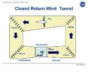
Closed-circuit involves circulating the air in a manner such that the wind tunnel does not either draw new air from, or vent it to, the surroundings. REF _Ref483675088 h * MERGEFORMAT Figure 3Figure 3 shows the configuration of a typical closed-circuit wind tunnel. The same air recirculates in the system in a controlled way and this ensures that the chances of dirt particles entering the system are very low. Therefore, closed-circuit wind tunnels have a more uniform flow as compared to open-circuit.
2.2.2 Category 2 Classification – Speed Regime
Wind tunnels are classified based on their maximum achievable speed. Traditionally, the ratio of the speed of any other object to the speed of sound is utilised. This ratio is called the Mach number, named after Ernst Mach. The classification is summarised in Table 1. Low subsonic or LSWT’s flow speed has a Mach number of 0.4. These types of wind tunnels are generally cost effective due to the low wind speed and design simplicity. LSWT is typically used in teaching and learning institutions such as colleges, schools and universities with low budgets. The maximum velocity of transonic wind tunnels can reach speed of sound of 412 m/s (meters per second) or Mach number of 1.2. These tunnels are commonly used in the aviation industry as most commercial aircrafts operate at this speed. Velocities of air in Supersonic wind tunnels wind tunnels can reach up to Mach 5. This is achievable by using divergent or convergent nozzles. These wind tunnels require large power input to function. Hypersonic wind tunnels’ velocity is between Mach 5 and Mach 15. They are used to test space vehicles and ultra-fast air craft.
| Name of flow or conditions | Range of speed in m/s | Range of speed in Mach number, M |
| Low Subsonic | Up to 137 | M < 0.4 |
| High Subsonic | 137 – 257 | 0.4 < M < 0.75 |
| Transonic | 257 – 412 | 0.75 < M < 1.2 |
| Supersonic | 412 – 1715 | 1.2 < M < 5.0 |
| Hypersonic | 1715 – 5145 | 5.0 < M < 15.0 |
2.2.3 Category 3 Classification – Educational or Research purposes
Wind Tunnels are also classified according to its purpose. If the wind tunnel is for research purpose, it is labeled as research wind tunnel. If it is specially designed for education use, it is labeled as educational wind tunnel. This will be elaborated in Section 2.3.1.
2.3 educational low-speed Open-circuit wind tunnel comparison
Wind tunnels are common in government and educational institutions. The table below shows a comparison of LSWT among universities and institutions. Example of Aerolab’s EWT users are University of Colorado and University of Arizona (United States), Kotelawala Defence University (Sri Lanka), and University of New South Wales (Australia).
Table 2
Comparison of Universities’ Open-Circuit LSWT data specifications
| Country | Name of Institutions | Test Section Specification | Speed Range | Contraction Ratio | Turbulence |
| Australia | University of New South Wales (EWT) | 3m x 3m | Up to 65 m/s | 9.5 to 1 | <0.2% |
| Belgium | The Von Karman Institute | 1.3m x 0.8m | Up to 45 m/s | 8 to 1 | <0.2% |
| Iran | Sharif University of Technology | 1.2m x 0.85m | Up to 80 m/s | 8 to 1 | <0.5% |
| United States | Purdue University | 0.5m x 0.3m | Up to 31 m/s | 25 to 1 | <0.3% |
| University of Michigan | 2.1m x 2.4m | Up to 50 m/s | 6.25 to 1 | <0.25% |
2.3.1 Usage of Educational Wind Tunnel (EWT) vs Research Wind Tunnel (RWT)
Many Wind Tunnels are known for its research purposes. RWT uses extensive high-quality instruments with superior materials in construction. It has the capability of obtaining all six force and moment components, with an accuracy of 1:3000. This translates to less than 0.1 percent result error (University of Michigan, 2017). RWT comes fully equipped with comprehensive systems too. However, this does not address the primary goals for educators from learning/teaching institutions, which is to inculcate students with theory and practice of experimentation (Ernst, 1983).
Reynold’s number (Re) is an important parameter in wind tunnel testing. It is a measure of ratio of inertia forces to viscous forces for given flow conditions that defines if the flow conditions are laminar or turbulent. The Aerolab’s Educational Wind Tunnel (EWT) is a compact version of a basic industrial-sized wind tunnel. It addressed the need to fulfill high-quality, affordable classroom tools. This provided simple and cheap alternatives to the private sector, academia and the military (Aerolab, 2017). The segregation between the two types of wind tunnels are made for several reasons. Firstly, a separate workstation helps to minimize interruption in researchers’ work in colleges or universities. Secondly, since EWT is a compact version of RWT, with simplified controls and system for educators to bring the message across, it is therefore appealing to budget-conscious customers such as many learning institutions. Thirdly, its compact sizing allows it to be fitted easily within most laboratory, while achieving the same work efficiency as traditional ones. Besides the many advantages, there exist some disadvantages of the EWT as compared to the RWT. As the EWT’s Re are not as close to RWT’s, smaller test sections meant smaller test-models, and scaled- down models. This thus decreased the results accuracy. Also, the basic components of the EWT is unable to achieve certain measurements unless additionally purchased. Despite these disadvantages, EWT is highly sought by learning institutions. This paper will continue to present on the EWT.
Hands-on experience is of utmost importance when education is concerned. EWT is built to provide valuable hands-on experience in a safe, simple and yet reliable understanding on aerodynamics. Teaching can be made easy without the complex research facilities or large-scale industrial wind tunnel (TQ, 2016). EWT is a compact and high-quality wind tunnel that comes with wide array of instruments to meet all laboratory and budgetary needs. This will be further presented in section 2.3.2. Where there is no risk of complications, putting theory into practice enhances learning process and experience. When it comes to planning, companies manufacturing EWTs have created basic set of experiments or even tailored ones to take the ease off educators. It can start as simple as learning the important first principles such as boundary layers, flow visualization, Reynold’s number and Bernoulli’s equation. Most importantly, it is cost and time efficient.
Some universities have multiple wind tunnels for different usages. Australia’s University of New South Wales School of Mechanical and Manufacturing Engineering’s laboratory facilities hosts five subsonic wind tunnels and one supersonic wind tunnel. It facilitates research work of aerodynamic testing of train, car, aircrafts, wind turbines, and roof ventilators, and provides educational teaching for students from various faculties (UNSW, 2017). United Kingdom’s University of Southampton has three wind tunnels: a 3’x 2’ tunnel is used for set-up work and project and calibration of instrumentations, a 7’x 5’ tunnel is used for undergraduate and postgraduate research projects, particularly for teaching and academic research, and lastly, the R. J. Mitchell tunnel is used for wide variety of industrial tests, including Indy Car and Formula One development work. (University of Southampton, 2016)
2.3.2 Aerolab’s Additional Features
 Educational Wind Tunnel gives alternatives to budget-conscious customers. The Aerolab’s basic EWT is a fully-functional wind tunnel that is upgradeable at any time the educator or researcher identifies a need to. Below, I present Aerolab’s optional add-on components to further enhance one’s capability, and the strength and flexibility of owning an Educational Wind Tunnel for educational purposes.
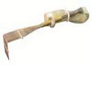
 Sting Force/Moment (Figure 4) – The basic EWT comes with a simple Force Balance component that measures only aerodynamic forces. However, to measure the pitching moment, Aerolab offers a 3-component “Sting” Force/Moment Balance. It measures Normal, Side and Axial Forces, Pitching, Yawing and Rolling Moment.
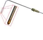
 Pitot-static probe (Figure 5) – Easily mounted in the EWT test section window probe port, it is a measurement of the dynamic pressure of a fluid in motion. It consists of a rounded-tip total- pressure tap and 6 static ports. Pitot-static probes can measure the different in total and static pressure, from which velocities can be calculated using the relation between dynamic pressure and fluid velocity (Hidayah & Hashim, 2012). Generally, the pitot-static probe is used in aviation and unmanned systems industries to determine its altitude, speed and Mach number.
Multi-manometer
- Data Acquisition, Display and Control System (DAC) (Figure 6) – It is capable of measuring, recording and displaying all types of instrumentation including force/moment balance output, position, temperatures, velocity and angle of attack. To further noise reduction, all analog sensor output signals are instantaneously converted to digital signals at source. The analog sensors are: pressure transducers, thermocouples, thermistors, stepper motors, rotary encoders and linear actuators.
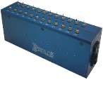 Pressure Transducer Array (Figure 7) – Multi-manometer, as shown in Figure 6, displays differing air pressures from 12, 18 or 24 input arrangements of Piezoelectric pressure openings in the Transducer Array. An airfoil develops lift through lower pressures above the wing and higher below with respect to the pressure of the approaching air. In addition, the lift force increases with higher angle of attack up to a critical angle. Beyond this critical angle the lift force decreases significantly and the wing is said to have “stalled”. The overall pressure distribution can be measured with small tubes embedded in the wing leading to a suitable pressure transducer. (Cattolica, Tynan, & Seshadri, 2014)
- Wake “Rake” (Figure 8) – consists of 18 total-pressure taps. The wake downstream of the model is measured with a rake consisting of total pressure and static pressure probes that feed into a single manifold to measure the averaged total pressure deficit in the wake of an airfoil. (Pifer, 2012)
2.4 3D printing Techniques/Additive manufacturing (AM)
Like the medical sector, the aerospace sector adopted 3D printing technologies during the earliest stages of its development. Companies worked with academic and research institutions to push boundaries of manufacturing application technology. Having already implemented AM in Research & Development (R&D) and prototyping, companies in these industries now show serious commitment to customized part manufacturing through 3D printing (IDC Research, 2017). Reputable and high-profile companies such as Airbus, Rolls-Royce, Boeing and EADS have taken realistic approaches to secure a stronger future in 3D printing technologies. It has aided General & Electric (GE) to produce all nineteen 3D printed fuel nozzles for their recent release of their LEAP engines that powers the new Boeing 737MAX and Airbus A320neo (Kellner, 2015). Government organisations like NASA have invested in its R&D in developing new alloys that allows 3D printed objects to survive in high heat environments and high speed while optimizing the engine’s strength-to-weight ratio (Scully, 2017).
2.4.1 Advantages and Disadvantages of 3D printing and CNC machining
Additives Manufacturing (AM) is excellent to produce intricate and complex designs as well as the manufacturing of prototypes. It reduces scrap metal by up to 90% compared to CNC machining (Scully, 2017). However, it is limited in terms of the variety of parts it can manufacture as compared to CNC machining. Further, the dimensional accuracy and surface finishing is not on par with what CNC machining can achieve. Printing doesn’t require human’s involvement after submitting for print.
CNC machines are suitable for geometric designs made from machining materials that require dimensional precision and quality surface finishing. More complex parts require skilled operators and CAD expertise, thereby increasing cost and lead time. CNC machine often requires more human input than 3D printers, with speed and quality heavily influenced by the operator.
Figure 9 compares the processes of 3D printing and CNC machining from start-to-finish. The simplicity of the former highlights that 3D printing has a bright future in the market.

Figure 9. 3D printing process (red) compared to CNC’s process (black) (3dhubs)
2.4.2 3D Methods Comparison
Table 3 compares the most common materials used in each class of 3D printing techniques. The type of bulk material used is the most vital factor that influences the properties of the final product in 3D printing technology.
Common 3D-printing techniques and its materials
| Printing Techniques | Materials Used |
| Fused deposition modelling (FDM) | Polylactic Acid (PLA)
Acrylonitrile Butadiene Styrene (ABS) |
| Multi Jet Modelling (MJM) | Acrylic Plastic |
| Selective laser sintering (SLS) | Thermoplastics, metal powders, ceramic powders Alumide, Nylon |
Table 4 presents significant parameters of the 3D printing techniques and materials discussed in Table 3. In summary, SLS with Alumide gave the best result, obtaining the highest tensile and flexural modules with the lowest fracture strain with medium surface roughness, while SLS with Nylon gave the 24% chance of fracture strain (elongation at break). While FDM produces strong parts, and demonstrates high thermal properties, it has the highest surface roughness due to the nature of process manufacturing. This makes it unsuitable for an aerodynamic object, unless it has gone through sanding or post-processing. MLM has excellent precision and quality surface finishing, however it has a long build process (Karalekas & Antoniou, 2004). FDM has the cheapest machine cost, followed by SLS. In comparison, machine cost was the major heftiest for MJM. It is thus clear that no single method is the best. Each has its own characteristics and functional use.
Table 4
3D-Printing Techniques and its technical data (Krzysztof & Piotrd.)
| MJM | FDM | SLS | SLS | |
| Material | Acrylic Plastic | PLA, ABS | Alumide | Nylon |
| Accuracy | ±0.025-0.05mm | – | ±0.15mm | ±0.15mm |
| Wall Thickness | 0.3mm | – | 0.8mm | 0.7mm |
| Tensile Strength | 26.2MPa | 22MPa | 48MPa | 48MPa |
| Flexural Strength | 26.6MPa | 41MPa | 72MPa | 58MPa |
| Fracture Strain | 9% | 6% | 4% | 24% |
| Thermal Properties | 46°C | 190-240°C | 172-180°C | 172-180°C |
| Density | 1.02g/cm3 | 1.05g/cm3 | 1.36g/cm3 | 0.93g/cm3 |
| Surface Roughness | Low | High | Moderate | Moderate |
| Recyclability | High | Medium | Non-recyclable | Medium |
| *Cost of printer (USD) | $70,000 to $200,000 | $500 – $5,000 | $2,000 – $15,000 | |
*Cost data retrieved from 3dhubs (2016).
Table 5 presents the cost and built time for wind tunnel models of three 3D techniques and CNC was included for comparison purposes. MJM has the lowest cost to build a sample model due to affordable resins, followed by FDM and SLS, where both techniques use filament. CNC fabricating aluminum or metal costs roughly ten times the amount, and four times the build time.
Table 5.
Cost and built time summary of CNC and the 3D printing techniques (Adelnia, Daneshmand, & Aghanajafi, 2006)
| 3D Techniques | MJM | SLS | FDM | CNC |
| Cost | $1000 | $1400 | $1200 | *$15,000 |
| Time | 2-4 weeks | 2-3 weeks | 2-3 weeks | *3.5 months |
Data retrieved from (Springer, 1998).
In summary, the accuracy of 3D printing was lower than of an aluminum or metal because of dimensional tolerance and surface finishing, but results were satisfactory and aerodynamic data for the level of preliminary testing phase. Currently, replacing machined-metal with 3D printed models for control surface effectiveness and detailed parametric aerodynamic is not practical due to the high configuration fidelity needed, and loads that deflects the control surface to be endured.
3) Methodology & Future Work
3.1 Setup of ewt in UNSW
The plan time to setup EWT optimistically begins in mid-end June. Setting up requires logistical planning and support as it will involve shifting from Ground Level to 1st Level. I will be assisting in the movement of the EWT during the break, and getting it set up and calibrated by end July. During my research year, I will be consistently working on EWT through means of research or calibration or trying out settings, also familiarizing myself with EWT’s software, LABVIEW. In the meantime, safety forms, procedures and manuals are to be created and documented before operations commence on the EWT. It will be used throughout the 2nd academic-semester, July – Nov 2017 for experimental and teaching purposes.
3.2 FUTURE WIND TUNNEL MODELS WITHIN UNSW
UNSW School of Mechanical and Manufacturing Engineering currently have five 3D printers. Two of them are SLA, one FDM, one SLS and one MJM. Based on the data comparison from Table 4, and the current availability of the printers, MJM and SLS are recommended for wind tunnel models due to low – moderate surface roughness. The design of the wind tunnel model is based on several variables such as its actual size, shape, speed, Reynold’s number, materials and production process. The design of the test model will be thought and done through the break and start of the semester 2. The plan is to produce one or two models for research, training and teaching purposes. The model(s) will be produced using the 3D printers available in UNSW, thereby saving time and cost. The printing of the wind tunnel model will be done in UNSW by August.
4) Conclusion
In summary, Educational Wind Tunnels play a vital role in teaching and learning institutions. They provide a simple and cheap alternative for the private sector, academia and the military. EWTs are equipped with tools and technologies for academic purposes and therefore cannot be compared with Research Wind Tunnels in terms of experimental result accuracy and data collection. The increase use of 3D printing technologies, along with the willingness of several high-profile companies to invest in Research & Development (R&D), will aid to strengthen innovation in the production of both aircraft parts and wind tunnel test models.
Acknowledgments
Most importantly, I want to thank God for His Blessings and Providence upon me. I want to appreciate my family for supporting and loving me even though I am many miles away from home. I would like to express my gratitude to my supervisor, Dr Zoran Vulovic, for having me as his thesis student and patiently guiding me throughout the course. Also, I would like to thank Omear, for teaching and showing me the ropes around the laboratory and wind tunnels, Tamsin and Eldad for assisting me in any queries and getting me acquainted with the 3D printing machines. Rahul Mohan, and Chuan Ling, who selflessly scarified their time to proof-read this paper.
References
(TQ), T. (2016). Technical teaching equipment for engineering. Retrieved May 28, 2017, from http://test.tecquipment.com/Aerodynamics/Subsonic/AF100.aspx
3DPI. (2016). 3DPI”s Beginner’s Guide to 3D Printing. Retrieved May 15, 2017, from https://3dprintingindustry.com/3d-printing-basics-free-beginners-guide/history/
Adelnia, R., Daneshmand, S., & Aghanajafi, S. (2006). Production of Wind Tunnel Testing Models with use of Rapid Prototyping Methods, 2006, 16–18.
Aghanajafi, C., & Daneshmand, S. (2010). Integration of Three-Dimensional Printing Technology for Wind-Tunnel Model Fabrication. Journal of Aircraft, 47(6), 2130–2135. https://doi.org/10.2514/1.C031032
Barlow, J. B., Rae, W. H., Pope, A., & Kassaee, A. (1999). Low-Speed Wind Tunnel Testing. John Wiley & Sons Canada, Limited. Retrieved from https://books.google.com.au/books?id=j8g5XwAACAAJ
Bournais-Varotsis, A. (2016). 3D Printing Technologies costing. Retrieved from https://www.3dhubs.com/knowledge-base/industrial-fdm-vs-desktop-fdm#production_capabilities_and_cost
Cattolica, R. J., Tynan, G. R., & Seshadri, K. (2014). Wind Tunnel Experimental Procedure, 1–12.
Feisel, L. D., & Rosa, A. J. (2005). The Role of the Laboratory in Undergraduate Engineering Education. Journal of Engineering Education, 94(1), 121–130. https://doi.org/10.1002/j.2168-9830.2005.tb00833.x
Franz Grieser. (2015). 3D Printing vs CNC: Explained and Compared. Retrieved May 25, 2017, from https://all3dp.com/3d-printing-vs-cnc-milling/
Hidayah, N. U. R., & Hashim, B. (2012). FABRICATING A SIMPLE FAN SYSTEM FOR SMALL LOW SPEED WIND TUNNEL AND STUDYING THE PARAMETER FOR FREQUENCY ADJUSTMENT.
IDC Research, I. (2017, February 7). European Aerospace and Healthcare Industries Leading 3D Printing Adoption for Finished Part Manufacturing but Still Facing Long List of Adoption Barriers. Retrieved from http://www.idc.com/getdoc.jsp?containerId=prEMEA42297617
Karalekas, D., & Antoniou, K. (2004). Composite rapid prototyping: Overcoming the drawback of poor mechanical properties. Journal of Materials Processing Technology, 153–154(1–3), 526–530. https://doi.org/10.1016/j.jmatprotec.2004.04.019
Kellner, T. (2015). The FAA Cleared The First 3D Printed Part To Fly In A Commercial Jet Engine From GE. Retrieved from http://www.gereports.com/post/116402870270/the-faa-cleared-the-first-3d-printed-part-to-fly/
Krzysztof, O., & Piotr, W. (n.d.). Evaluation of 3D Printed Aerofoil Models for Wind Tunnel Testing, 257–262.
Martinez, D., Meaurio, C., Alviso, D., Chaparro, J., Vargas, E., & Rolon, J. C. (2016). Design and Implementation of an Aerodynamic Balance in a Subsonic Wind Tunnel and Validation Through Numerical and Experimental Investigations of Lift and Drag Performances on Airfoils.
NASA. (n.d.). Figure 2: Diagram of an Suckdown Tunnel. Retrieved from https://www.grc.nasa.gov/www/k-12/airplane/Images/tunoret.jpg
Pifer, E. A. (2012). Measuring Wing Profile Drag using an Integrating Wake Rake. Technical Soaring, 36(3), 74–82.
Pope, A., & Rae, W. H. (1984). Low-speed wind tunnel testing. Wiley. Retrieved from https://books.google.com.au/books?id=Q_5TAAAAMAAJ
Scully, L. (2017). Metal 3D Printing to Shape the Aerospace Industry. Retrieved from http://www.machinedesign.com/3d-printing/metal-3d-printing-shape-aerospace-industry
Springer, A. (1998). Evaluating Aerodynamic Characteristics of Wind-Tunnel Introduction, 35(6), 1–5. https://doi.org/10.2514/2.3412
University of Southampton. (2016). University of Southampton Wind Tunnels. Retrieved May 26, 2017, from http://www.southampton.ac.uk/windtunnels/facilities/index.page?
UNSW School of Mechanical and Manufacturing. (2017). Aerodynamics. Retrieved May 28, 2017, from https://www.engineering.unsw.edu.au/mechanical-engineering/study-with-us/facilities/aerodynamics
Appendix A
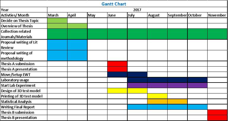 Gant Chart Timeline
[1] wong.nelsonts@gmail.com
Cite This Work
To export a reference to this article please select a referencing stye below:
Related Services
View all


Related Content
All TagsContent relating to: "Physics"
Physics is the area of science that focuses on various aspects of nature, energy, and other areas of natural science. The main purpose of physics is to use experiments and analysis to develop a greater understanding of the universe's behaviour.
Related Articles

DMCA / Removal Request
If you are the original writer of this dissertation and no longer wish to have your work published on the UKDiss.com website then please: