Electric Motor Characterization Investigation
Info: 9794 words (39 pages) Dissertation
Published: 10th Dec 2019
Tagged: EngineeringElectronics
Part 1: Electric Machine Characterisation
This part relates to the electric machine characterisation practical session. Write a critical discussion of the investigation undertaken, the results produced and relevance of the activity to real-world automotive applications.
Try to utilise appropriate academic literature to support the points you make and justify any conclusions. Also try to make links between the activity undertaken and challenges automotive engineering. Interpret and conclude on the results obtained rather than simply presenting them.
This part accounts for 20 marks out of 100 marks for this PMA. Suggested number of words for answering this part are 1500.
Part 2: Structured Essays
This part contain 2 sections:
Section 2.1: Write an essay entitled “Permanent Magnet Based Electric machine for Hybrid and Electric Vehicle applications”. The content should address the following points:
- Select a particular hybrid or electric vehicle into which a permanent magnet based electric machine is to be incorporated. Upon deciding the vehicle type (e.g SUV) and architecture (BEV), specify the required technical specifications of such a permanent magnet electric machine.
- A detailed description of the construction, principle of operation, manufacture and reliability of the permanent magnet based electric machine should be included. Use the technical specifications to guide this section.
- Describe the required control algorithm and power electronics need to drive such an electric machine in your chosen vehicle type.
- Describe the integration challenges of incorporating this complete system, including the thermal, electromagnetic, mechanical and electrical considerations. Consider end of life scenarios.
Section 2.2: Choose at least one future direction of research in the area of permanent magnet based electric machines for hybrid and electric vehicles. Include the motivations for this area of investigation and critically review it. Use appropriate literature to support the points you are making.
This part accounts for 50 marks out of 100 marks for this PMA. Suggested number of words for answering each section in this part is approximately 1300.
Effort and Coverage:
- Engineering and academic rigour.
- Use of references.
- Evidence of learning beyond the taught material.
- Depth and breadth of topic coverage.
- 15 marks are available.
Presentation:
- Document structure, spelling and grammar.
- Quality of communication.
- Use of diagrams, figures and tables.
- Format of references and bibliography.
- 15 marks are available.
Guidance for this PMA:
- Expect to spend approximately 60 hours on this assignment (this includes time spent on, for example, reading, which will be in addition to the time spent during the taught week.)
- Present the assignment at sufficient depth to demonstrate attainment of the key learning outcomes for this module.
- The format of presentation should be on a single, concise document, with appropriate formatting such as cover page (including name and student ID), page numbers, contents, introduction and conclusions,.
- Relevant diagrams, figures and calculations should be included.
- Ensure that the diagrams, figures and graphs are presented and labelled appropriately.
- Extracting key points of learning from the results, particularly from lengthy or complex calculations, is strongly encouraged.
- The assignment must be written in a technical and academic style.
- Utilise a variety of quality references to demonstrate learning beyond the taught material. Appropriate sources include:
- Journals and conference material from the Society of Automotive Engineers
- IEEE journals and publications
- IMechE and IET journals
- Text books and other peer-reviewed academic works
Marks Summary
Part 1 20 Marks
Part 2 50 Marks
Effort and Coverage 15 Marks
Presentation 15 Marks
PMA Total 100 Marks
MODULE TITLE
Table of Contents
Part 1: Electric motor characterization
1 Introduction
The aim of conducting these tests is to obtain the parameters for PMSM, which can be utilized in EV’s for on board simulation and analysis. The electric motor characterisation in the practical session deals with the measurement of electrical parameters, which can be used for vector control of the PM electric machine. These parameters are useful to set the gains for the PID controller and for sensorless control applications (Musak and Stulrajter, 2013)
The tests are conducted on Electric Motorsport PMAC-G8455 kit. The motor is a 10 kW three phase, Y-connected PMSM with four pole-pairs. A resolver is used for position sensing. The AC motor controller is a high efficiency Gen4-series using flux vector control. The testing was conducted in a thermal chamber using a dynamometer with temperature maintained at 25-degree Celsius.
2 Open Circuit Test
The open-circuit characteristic of a synchronous machine is a curve of the open-circuit armature terminal voltage as a function of the field excitation when the machine is running at synchronous speed (Fitzgerald, 2003).
Open circuit test is used to measure the back EMF which is the voltage generated by the electric machine when it is spinning. This test is essential in motor characterization as the velocity constant KV can be calculated using the BEMF. The velocity constant can be used to estimate the BEMF for any given RPM. Velocity constant is one of the essential parameters that can be used to estimate the speed of the motor using BEMF sensorless speed control techniques (Genduso et al., 2010)
The stator windings are not connected to load. A dynamometer is used to rotate the motor at different speeds .The test is carried in a room with constant temperature. The BEMF can be calculated by measuring the line-to-line voltage.
| S (RPM) | VOC (V) | Velocity Constant (RPM/V) |
| 500 | 6.49 | 76.94 |
| 1000 | 12.70 | 78.70 |
| 1500 | 19.28 | 77.78 |
| 2000 | 25.75 | 77.65 |
Figure 1: Open Circuit Test (Source: Practical Results)
3 Current Injection Test
Electric machines in automotive applications operate in varying conditions. Stator resistance is one of the parameters that indicates coil temperature in an electric motor. Monitoring the coil temperature of the electric motor is crucial to fully extract its thermal capacity. The process of directly measuring the coil temperature of the motor is complex and expensive. Hence, the temperature can be estimated by measuring the stator resistance. (Wilson, Stewart and Stewart, 2012)
The equation to find coil temperature is,
Ts=Rs-RsoαRso+To #Eq. 1
Where ‘Ts’ is the coil temperature at resistance ‘Rs’, ‘To’ is the coil temperature at resistance ‘Rso’ and ‘
α
’ is the temperature coefficient of copper.
In this test, the stator resistance is determined using voltage and current through the coil. The stator resistance is essential to define the shape of torque speed curve. The stator losses under open load are determined in this test. (Akin, Ertan and Uctug, 1994).
| I (A) | V (V) | R (Ohm) |
| 5 | 0.06 | 0.0120 |
| 10 | 0.1229 | 0.0122 |
| 15 | 0.1835 | 0.0122 |
| 19 | 0.2326 | 0.0122 |
Figure 2: Stator Resistance Measurement (Source: Practical Results)
In this test, a variable current was applied and the corresponding voltage between two phases were measured. Using Ohms law, the phase-to-phase winding resistance is calculated to be 0.012 Ohms. This value is similar to the specified phase-to-phase winding resistance of 0.013 Ohms. The deviation from the specified value is minimal and is caused by variance in signal measurement and processing.
4 Short Circuit Test (Stator Inductance Measurement)
The test is conducted at low rotational speed. The advantage of this is that the PMSM model is linearized at low speeds, as the cross-coupling terms in both d- and q-axis and back-EMF voltage component in q-axis are cancelled. (Musak and Stulrajter, 2013)
Due to the PMSM crucial structure and the EMF obstruction, the calculation of the d-axis and q-axis inductances is complex. The short circuit test is one the simplified methods that can be utilised to calculate the inductances.
This test is crucial as there can be a situation during the life time of an EV, when it may be subjected to a short circuit due to an accident or a fault. Even though the primary function of electric motors is to provide traction in an EV, the motor is far more complex as it is designed to withstand a short circuit situation.
In this test, the three terminals of the motor are short-circuited. The motor is rotated at low speeds and the resulting current and torque produced are measured.
D and q axis
| S (RPM) | Iarms (A) | Ibrms (A) | (Ia-Ib)rms (A) | EMF (V) | Torque (Nm) | L (H) |
| 50 | 69 | 65 | 115 | 0.714 | 14.1 | 0.095 |
| 100 | 124 | 120 | 207 | 1.25 | 24.2 | 0.119 |
| 150 | 164 | 161 | 277 | 1.875 | 29.3 | 0.090 |
Figure 3: Stator Inductance Measurement (Source: Practical Results)
As this test is a simplified method to measure inductance, the results will not be of high accuracy. There is also a safety aspect to be considered when conducting this test, as a short circuit scenario can be dangerous to the equipment and its surroundings. (Jäger, Grinbaum and Smajic, 2017)
5 Electrical Loading Test
There has been a lot of development in PM motors, power electronics and their control equipment. PMSM are associated with low loss and high peak efficiency. In EV’s, the load on the electric motor frequently varies and the analysis of the effect of these load changes on the electric machine are essential for an optimal design. This system is mostly used in prototype electric machine testing to analyse its performance before going into production. (Wang and Liu, 2011)
For an automotive manufacturer, it is essential to analyse the efficiency of the motor under different load conditions. The maximum efficiency for a PM motor is at approximately 75% load. Even though motors are designed for occasional overloading, continuous under loading or overloading can cause the motor to heat and efficiency will be reduced drastically.(US (Dept. of energy), 2012)
| Vin (V) | Iin (I) | Pin (kW) | WA (W) | WB (W) | PAC (kW) | T (Nm) | S (RPM) | POUT (kW) |
| 65 | 19.5 | 1.26 | 518 | 720 | 1.23 | 20 | 500 | 1 |
| 65 | 35 | 2.27 | 720 | 1350 | 2.07 | 20 | 1000 | 2.1 |
| 65 | 52.5 | 3.41 | 1341 | 1949 | 3.29 | 19.5 | 1500 | 2.9 |
| 65 | 65 | 4.22 | 1837 | 2263 | 4.10 | 18.5 | 2000 | 4 |
| 65 | 85 | 5.55 | 2192 | 2820 | 5.01 | 18 | 2500 | 4.7 |
| 65 | 102 | 6.66 | 3392 | 2951 | 5.54 | 17.5 | 3000 | 5 |
| 65 | 108 | 7.02 | 4000 | 2500 | 6.5 | 16 | 3500 | 5.6 |
| 65 | 121 | 7.85 | 4638 | 2650 | 7.28 | 15 | 4000 | 6.5 |
| 65 | 108 | 7.02 | 4897 | 1807 | 6.74 | 11 | 3500 | 5.11 |
Figure 4: Electrical Loading Test (Source: Practical Results)
In this test, the motor is connected to the dynamometer. A 65 V supply is connected to Sevcon drive and the three phase output is connected to the motor. The motor speed is varied and different parameters are measured, from which the inverter input power, inverter output power (motor input power) and the motor output power is calculated.
Currently there are different online parameter estimation techniques, to calculate the electric machine parameters when on load and are advantages as the parameters can be measured in real time. However, at present there are no alternative methods to electrical loading test to accurately estimate the motor parameters.(Liu, Zhu and Stone, 2013)
Electrical loading test analyses the conversion efficiency of the inverter and the electric motor. Along with the individual components, this test is used to characterize the complete system under different loading conditions, loading speed profile and generate the efficiency map. Sub-assemblies can be tested individually to build an efficient final electric machine. This test is automated to provide output under variable conditions.
Swirching losses
6 Conclusion
It can be observed that the test results are simple to interpret and correlate with actual values, implying that these testing techniques are useful to analyse the characteristics of the electric machine. The accuracy of the results obtained is confirmed by comparing with the specified values. The parameters required for computational simulation can be obtained using these tests. These tests can be used for investigating contamination in the winding and insulation faults that result in an output surge. Prototypes of electric machine can be tested and modifications can be made to get the desired parameter values.
Part 2.1: Structured Essays: Permanent Magnet Based Electric Machine for Hybrid and Electric Vehicle Applications
7 Introduction
8 Design Specification
In this report, a permanent magnet based electric machine design is proposed SUV with a 150kW traction motor powering its rear wheels. Write abt poles
9 Electric Propulsion Design
The electric machine is a vehicle are made of three main components
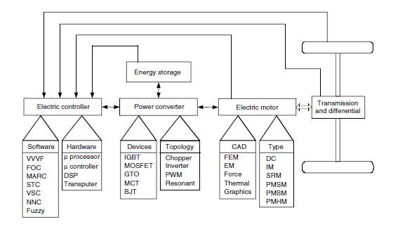
Figure 5: Electric Propulsion System Design (Ehsani, Yimin and Miller, 2007)
9.1 Electric Motor
The electric motor converts the electric energy to mechanical energy using EMF to provide traction. There are numerous benefits of integrating permanent magnets in electric machines for field excitation. Unlike IM and SRM, PM machines do not require rotor-winding excitation due to use of permanent magnets. The PM can produce magnetic field in the air gap without excitation and electric energy. This results in low losses, leading to higher efficiency, as they do not require external excitation. However, they are susceptible to varying rare earth magnet cost and are complicated to manufacture making them expensive. (Yildirim, Polat and Kurum, 2014)
Traditionally brush PM motors were common; they had the magnets integrated into the stator. The disadvantage of this design was that the electricity had to be supplied to the rotor through brushes and commutators. They required periodic maintenance of the brushes and suffered from significant losses at high speed. A brushless PM motor does not require brushes due to the integration of magnets into the rotor. They benefit from low losses, are capable of supplying higher torque and require low maintenance.
The PWSM can be DC or AC based on the shape of the BEMF of the voltage produced during rotation. The magnets, windings and the laminations dictate the shape of the BEMF. Brushless AC machines produce a sinusoidal waveform and have high efficiency. They have low torque ripple and have higher accuracy in control. Brushless DC machines produce a trapezoidal BEMF. They are simple to design but suffer from higher torque ripple. Due to the higher efficiency, a BLAC motor is implemented in this design. (Krishnan, 2017)
9.2 Power Converter
The power converter supplies the EM with the required voltage and current. Transistors are used as power devices due to their fast switching and low loss characteristics.
| BJT | MOSFET | IGBT | |
| Drive Method | Current | Voltage | Voltage |
| Drive Power | High | Low | Low |
| Switching Speed | Moderate (100 kHz) | High (500 kHz) | Low (50 kHz) |
| Current Ability | Low | High | High |
| Voltage Ability | High | Low | High |
| Drive Circuitry | Complex | Simple | Simple |
Figure 6: Comparison of Power Devices (Krishnan, 2017)
IGBT is a combination of MOSFET and BJT properties. IGBT are capable of high voltage as well as high current, making them high power devices. The gate has complete control over the operation of the IGBT.
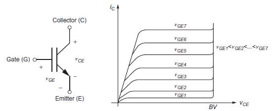
Figure 7: (a) N-channel IGBT Symbol (b) Static Characteristics of IGBT (Busarello, Simões and Pomilio, 2017)
IGBT’s are limited only by their switching speed. Even though there is ongoing research to improve the switching speeds of the IGBT, they still are much slower than BJT and MOSFET. They have a simple gate drive circuitry as they have a voltage controlled drive circuit and have low ON losses making them ideal for automotive applications. (Busarello, Simões and Pomilio, 2017)
9.3 Electronic Controller
The electronic controller behaves like a control unit; it provides control signals to the power converter in the form of PWM. It also controls the electric motor by providing the necessary torque and speed as per the driver requirements.
10 Design Parameters
10.1 Field Flux Direction
The electric motor can be classified based on the flux field orientation; radial and axial field motors. Axial motors, also known as “pancake” motors have high torque capability and used when space is a constraint, especially in hybrids and in-wheel motors. Radial flux motors are common in automotive industry and benefit from high speed. They are excellent for the design for a BEV in this paper as its size is not a major constraint. (Qu, Aydin and Lipo, 2003)
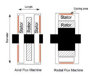
Figure 8: (a) Axial Flux Machine (b) Radial Flux Machine (Source: Class Notes)
10.2 Winding
The PMSM windings can be distributed or concentrated depending on the slots and poles available in the motor. The concentrated windings have lower losses and are highly efficient in comparison to distributed winding. Whereas distributed windings have better high speed, efficiency and lower torque ripple. In this design, the merits of distributed winding are more desirable.
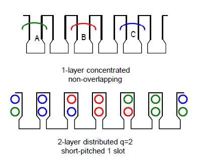
Figure 9: (a) Concentrated Winding (b) Distributed Winding (Source: Class Notes)
Three-phase power supply is used due to increased efficiency over single-phase power supply. Although higher number of phases mean increased efficiency, the output of a three-phase supply is optimum to the requirement of the motor. Having more than three phases means increasing the complexity, when the efficiency gained is not justifiable.
Winding can be connected in either star or delta configuration. Star connection consists of three phases connected at a common neutral point. Delta connection consist of three phases and a ground.
| Connection Type | Line Voltage | Line Current |
| Star | VL= √3 x VP | IL= IP |
| Delta | VL= VP | IL= √3 x IP |
Figure 10: Line Voltage And Current For Star And Delta Configuration (Alexander and Sadiku, 2001)
In this report, a star connection winding is selected, as only three wires are required between the inverter and motor and benefits from higher line voltage.
10.3 Rotor Types
The magnets in a rotor can be placed differently. The basic principle of the motor operation is the same regardless of the placement of the magnets. The commonly used rotor types in automotive and industrial applications are analysed in this section.
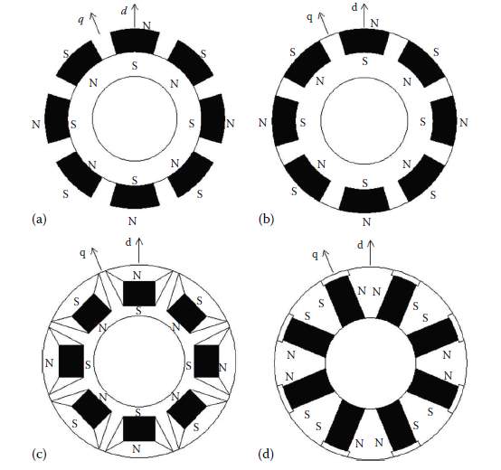
Figure 11: (a) Surface PMSM (b) Surface Inset PMSM (c) Interior PMSM (d) Interior PMSM with circumferential orientation (Krishnan, 2017)
10.3.1 Surface mounted PMSM (SPM):
Magnets are mounted on the outer edge of the rotor. This placement of the magnet benefits from the higher air gap flux density due to no interruptions of the magnets with the air gap. Structural rigidity is an issue as the magnets are not fully integrated into the rotor and are thus not preferred for high-speed applications that are subject to large centrifugal force.
10.3.2 Surface inset PMSM (SIPM):
The magnets are placed in channels in the outer diameter of the rotor. This design is mechanically robust, as the magnets are placed within the rotor diameter and do not project out. Even though they have a lower air gap flux density than SPM, they compensate for it with the ability to work in high speed applications.
10.3.3 Interior PMSM (IPM):
The magnets are placed within the rotor in horizontal positions. This is mechanically robust and can work at high speeds. The manufacturing is complex, as the magnets need to be embedded into the rotor. The motor suffers from low air gap flux density as the rotor can act as a barrier for the flux. Some rotors have conduits cut out to facilitate better flow of flux and help with weight reduction.
10.3.4 Interior PMSM with circumferential orientation:
The magnets need to be large and thus is expensive. Due to the placements of the magnets, the energy density is quite low.
In this design, a surface inset PMSM is selected due to the balance between energy density and mechanical rigidity.(Krishnan, 2017)
10.4 Magnetic material
There are different magnetic materials available for applications in PMSM. Magnetic materials in electric motors are present to generate magnetic flux. Hence, the material needs to have a high magnetization and be inexpensive.
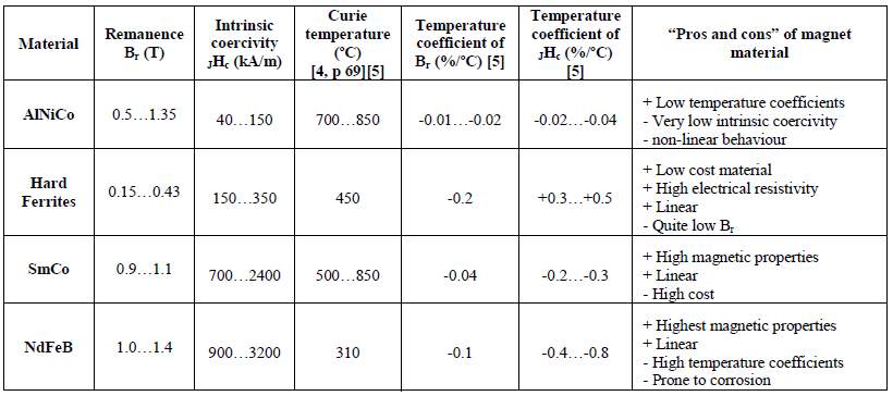
Figure 12: Comparison Of Permanent Magnet Materials (Ruoho, 2006)
Hard magnetic materials are the materials that can be permanently magnetised. In the comparison between the different magnet materials for PM, high coercivity is critical, as it is the capability of the material to resist demagnetisation. Even though Neodymium magnets (Nd-Fe-B) belong to Rare Earth magnet and are associated with high magnetic properties and linear nature, they are not suitable for motor applications due to its instability when surrounded in an electric field at high temperatures. This limitation is overcome with Nd-Dy-Fe-B material, which is an addition of dysprosium (Dy) material to Nd-Fe-B, which increases the intrinsic coercivity and makes it stable at high temperatures. (Gutfleisch et al., 2011)
11 PMSM Operational Sensing
11.1 PWM Signal Modulation
Pulse width modulation is used to control the motor by using digital control signal. It uses a fixed frequency and a fixed period signal with variable duty cycle. The longer the ON pulse, the faster the motor will rotate.
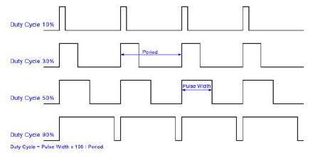
Figure 13: PWM Signal Modulation (Source: Class Notes)
By varying the duty cycle in PWM, any type of waveform can be created. Using PWM, the sine wave can be approximated as shown in the figure below.
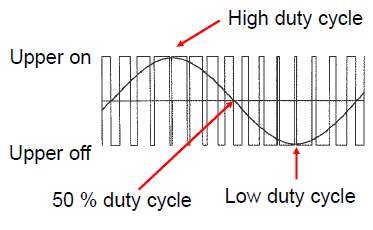
Figure 14: Sine Wave Created Using PWM (Source: Class Notes)
Switching losses are incurred for every ON-OFF cycle leading to EMC. There are different switches that can be implemented. However, transistors are used due to their high switching speed and low switching losses. An inductance in the load creates a smoother current profile. The energy that can be stored in an inductance is limited, leading to limitations in the power delivered during the OFF cycle. The type of switch used has a large impact on the switching losses. (Weber, 1965)
11.2 Rotor Position Sensor
Rotor position sensor is essential to provide feedback signal with respect to the rotor position. This feedback is used to match the variable frequency converter to the motor and mechanical inertia to generate torque. During regenerative braking, synchronisation is necessary for controlled braking. Position sensors are necessary to determine the position and speed of the rotor.
11.2.1 Encoder
Optical encoders are of two types: absolute and incremental encoders. Optical encoder is a simple system where a light is passed through transparent areas in a disk and is sensed using a photodetector.
An incremental encoder counts the output pulses using a reference point on the disk. It consists of two tracks. The limitation here is during the first turn, the reference point has to be detected to start counting.
An absolute encoder is a position verification device. It has unique information for every position and the accuracy is determined by its resolution. It can identify the position from the first rotation and does not need a reference point, as each point is unique. (Gieras, 2009)
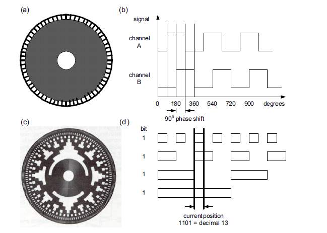
Figure 15: Incremental Encoder (a) disk (b) output and Absolute Encoder (a) disk (b) output (Gieras, 2009)
Encoders benefit from simple digital interface and have predictable noise characteristics. They are large and are prone to environmental conditions. The process of manufacturing an absolute encoder is complex and requires high precision, as the deviation tolerances are low.
11.2.2 Hall Effect Sensor
A magnetic field sensor outputs a voltage based on the current fed and the surrounding magnetic field. It is an inexpensive and low accuracy sensor and has limited capability at high temperatures.
11.2.3 Sensor less
Sensor less does not require any hardware and uses algorithms to estimate the position of the rotor. It benefits from lower cost and does not have limitations related to environmental conditions. There are different techniques to obtain the rotor position:
- Back EMF detection
- Stator 3rd harmonics
- Inductance variations
During start up, the position data is not accurate, but as the rotations increase, the motor can get feedback and then the accuracy will increase. Even though there is no hardware cost involved, it is complex to implement and currently there are no high accuracy sensor less techniques in production vehicles. (Yongdong, Hao and Open, 2008)
11.2.4 Resolver
A resolver uses a resolver position sensor, which is effectively a variable transformer; it provides output in the form of trigonometric functions for given inputs. This data is interpreted in a complex analogue resolver to digital converter. The position of the rotor can be obtained from the difference between the sine and cosine signal. Resolvers are analogue devices and hence are more tolerant to vibration and environmental variations. (Murray and Hare, 2002)
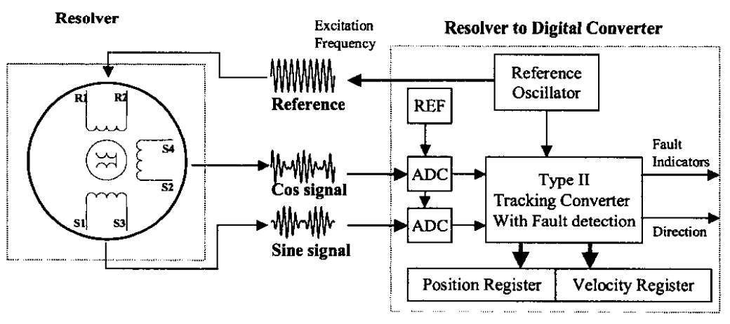
Figure 16: Resolver Position Sensing System (Murray and Hare, 2002)
Resolvers are inexpensive, compact and rugged making them favourable for the design in this paper.
11.3 Temperature Sensor
Temperature sensing in an important aspect in motor design. The windings can melt if sufficient cooling is not supplied. Ideally, multiple temperature sensors placed throughout the windings would help provide better data.
Thermistors are an inexpensive option but cannot accurately read over 120 degree Celsius. The motor windings can easily exceed these temperatures. Infrared can be accurate and no physical connection is required to the moving part. However, it can only measure the rotor surface temperature and not the actual winding temperature. By developing a thermal model, the cost can be reduced; however, it is complex and suffers from low accuracy. A well-designed thermistor for high temperatures is suitable for this design proposal.
12 Machine Control
There are two main aspects to machine control
12.1 Commutation
Commutation is specific to the technology of the electric machine implemented. It is positioning the magnetic field so that force is perpendicular. It is the process of optimally selecting the phase to rotate the motor in the required direction. A Six step switching is used in a three phase-star topology motor. In this design, IGBT’s are used as switches with diodes in parallel to facilitate reverse current flow.
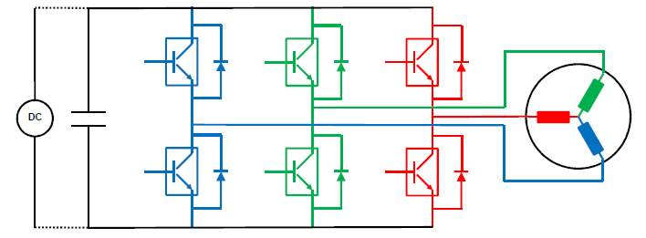
Figure 17: Simplified Three Phase Bridge Control of Motor (Source: Class Notes)
The six switches present are switched in pairs to ensure that the upper and lower switches are never at same position (on or off). This is done to prevent “shoot through” which can be caused due to short circuit. There is a redundancy mechanism in place in the form of dead bands during switching. There is a second redundancy in the form of logic gates which does not prevent both the transistors to switch on or off at the same time as well.

Figure 18: Different states for switches during operation and direction of current flow (Source: Class Notes)
For a three phase motor, there can be 23 types of combinations for the switching states. Based on the switches that are on and off, the direct of current flow changes as shown in the above figure. The states when all three switches are on or off cannot exist. The switches can be advantageous as they can be used for PWM and commutation.
12.2 Regulation
Regulation is the current control depending on the torque requirement. Torque is produced by the interaction of the magnetic fields and is controlled by regulating the current. Torque measurement is not present in the vehicle; hence, current is measured, as the current is directly proportional to torque.
The motor has an inbuilt inductance. Unlike voltage, which can be digitally switched on and off, current takes time to rise and fall. By changing the state of the switch, variable current control is achieved. The supervisory controller and the accelerator pedal position sensor specify the controlled target.
Control can be either open or closed loop. The open loop control does not account for variability; however, it is simple to design. The closed loop control constantly measures and adjusts to match the target based on the feedback. It is complex and expensive; however, better performance can be achieved. In this paper, a closed loop control is considered due to the improved response and performance.
12.2.1 Hysteresis Control
Hysteresis controller is a feedback loop with two comparators. It uses a tolerance band (h) around the required target (iref) within which the current is maintained. There is a trade-off between switching frequency and accuracy due to switching losses. (Guoqiang and Jianli, 2010)
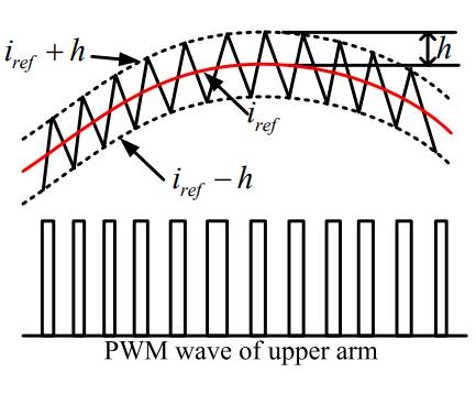
Figure 19: Principle of Hysteresis Control (Guoqiang and Jianli, 2010)
12.2.2 PID Control
Proportional–Integral–Derivative (PID) is a three-term controller for automatic control field. It adjusts the output with a weighed mix of three factors
- Proportional to the error (P): Shifts the output in proportion to the error
- Integral of the error (I): Shifts the output proportion to the duration and magnitude of the error
- Derivative of the error (I): Shifts the output in proportion to the speed of approach
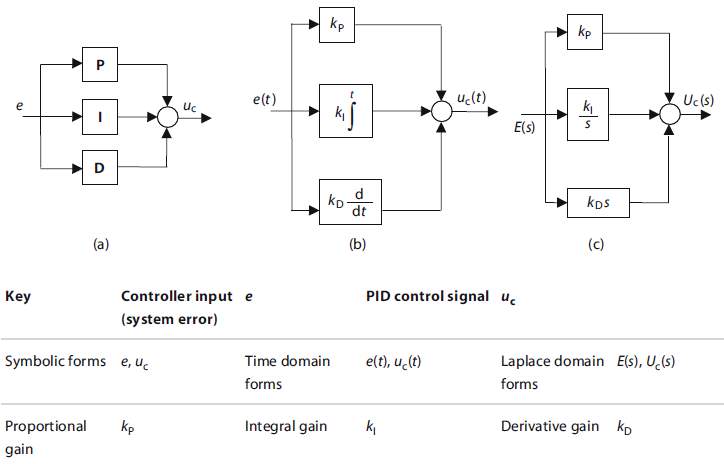
Figure 20: PID Control Representation (Johnson and Moradi, 2005)
PID controllers are commonly used in the industry due to their simple and efficient application. The gains need to be calibrated to get the desired response and there are various techniques available such as the Ziegler-Nichols method which can be implemented. (Foley, Julien and Copeland, 2008)
13 Thermal Management
An optimal thermal design is as crucial as the electromagnetic design to the electric machine, as it can have a considerable increase in the continuous performance of the PM machine.
13.1 Stator Cooling
PM motors have low heat losses, as they are highly efficient. Indirect conduction is cooling the stator using a heat exchanger at its external surface. PM motors have a thin yoke, due to which high heat transfer is possible. Cooling is performed using air, coolant or oils. High heat transfer rate can be achieved using direct cooling. Dielectric fluid is used to cool the windings directly. High power density can be extracted from the motor due to the increased cooling. (Gieras, 2009)
13.2 Rotor Cooling
In a PM motor, high heat build-up can lead to demagnetisation. In passive air-cooling, the rotors circulation is used to cool the rotor. Forced air-cooling requires an extra motor to circulate the rotor cavity air. It requires additional hardware but benefits from increased cooling. In this paper, a closed loop internal cooling is selected which circulates liquid oil inside the rotor. It requires rotating shaft seals but has the highest heat transfer. (Gieras, 2009)
14 Failure Mechanisms
Electric machines are generally reliable, but they do wear out and can fail as any other electro mechanical system. The different systems that can fail are
14.1 Machine failure
It consists of the mechanical failure that can occur such as
- Insulation Failure (Short Circuit)
- Connection Failure (Open Circuit)
- Demagnetisation
- Mechanical bearing failure
- Catastrophic rotor failure
14.2 Power Electronics Hardware Failure
The E-Machine consists of various power electronics devices and sensors. The components need to be well designed to prevent premature wear, open circuit or short circuit situations. Position sensors such as voltage sensor, current sensor and position sensor are essential to the control of the machine. Any incorrect information due to their failure can catastrophic damage to the inverter.
14.3 Control Software Failure
The control system is responsible for the operation of the E-machine. The failure can be caused due to software issues, failure of the controller hardware and due to communication failure. A well-designed system with redundancies should be able to prevent these failures.
14.4 ASIL Rating
Automotive safety integrity level is a key concept within the ISO26262 functional safety standard. It provides a robust framework for identifying and controlling the risk of personal injury due to these systems. There are three dimensions to ASIL:
- Severity
- Exposure
- Controllability
A common strategy employed by manufacturers is to reduce the required ASIL rating during the design to keep safety critical elements to the minimum. This makes the design process less complicated and can save the manufacturer lot of development costs.
Mechanical design reliabilty
EOL
Part 2.2: Future Direction of Research in the Area of Permanent Magnet Based Electric Machines for Hybrid and Electric Vehicles
15 Introduction
PM motors are used in EV’s due to their high efficiency, simple construction and low maintenance. As the demand for EV’s is increasing exponentially, there is a need to understand how PM machines can be enhanced in the future (Petrov et al., 2017). Although PM motors have several advantages, the major challenge currently is to find an alternative to scarce and expensive rare earth materials. Rare earths are concentrated geographically in china and japan making it inconsistent while sourcing and pricing. Material engineers are researching for an alternative to find equivalent cheaper ferrite components with similar magnetic properties (Pavel et al., 2017). Despite this challenge, PM motors continue to be preferred and future research seems encouraging.
The integration of the electric motor and the inverter into a single unit is referred to as integrated motor drive. The benefits of integration are lower interference, improved modularity etc. Currently the research is focussed towards In-wheel motor drive which integrate the motor and power electronics onto a single unit mounted on the wheel.
16 Motivation
The In-wheel motors have numerous functional and control benefits.
16.1 Lower EMC
The electromagnetic field around the high voltage cables in an electric machine is a source of interference. In a conventional electric machine, the inverter and the electric motor are placed individually, giving flexibility in packaging them in the space available. Depending on their placement in the vehicle, the amount of HV cabling required to connect them varies. HV cables are difficult to route throughout the vehicle, can induce unwanted currents in nearby conductors, and can interfere with the control system. (Guttowski et al., 2003)s
16.2 Lower Weight
The elimination separate enclosure, long cabling and complex cooling system for the electric machine reduces the machine weight substantially. It benefits from low centre of gravity as the motors are placed low, improving the handling of the vehicle.
16.3 Lower Volume
The integration of the inverter and electric motor into a single unit reduces the system volume. By downsizing the components and making the motor drive compact, the saved space can be used for the passenger compartment, battery storage or other purposes. (Jahns, 2017)
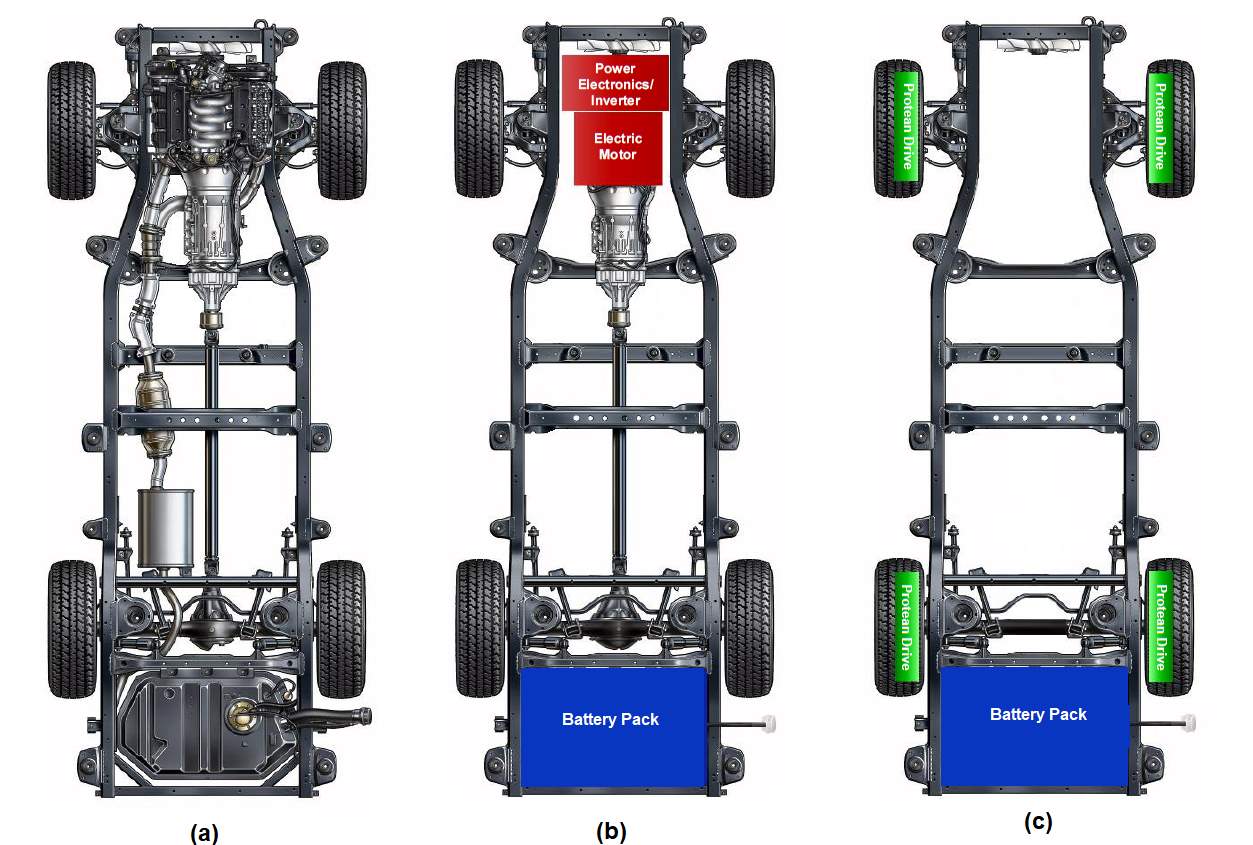
Figure 21: Vehicle Layout (a) Conventional ICE (b) Conventional EV (c) In-Wheel Drive (Murata, 2012)
In wheel PM motor are favourable as they are efficient by minimising transmission losses. Their smart topology provides electronic differential action. In-wheel PM frees up space that would have been otherwise used by differential gears. The space saved can be used to extend the passenger compartment, additional batteries or additional luggage space. (Wu, Song and Cui, 2007)
17 Design
17.1 In-Wheel Motor
The in-wheel drive motor requires compact design with integrated electronics. The electronics are subject to vibrations and environmental conditions, hence they need to be well sealed. The torque produced is proportional to the air gap radius. By selecting the largest air gap radius, the torque can be maximised. The design and delivery of in wheel motors is highly challenging to meet the environment constraints, torque and speed requirement, safety, and restricted packaging space.
Many Research and design teams have come up with innovative future designs for in wheel motors. Protean electric (Perovic, 2012) have come up with a direct drive based brushless PM machine with an outer ring. The power electronics are integrated to provide higher efficiency and reduced coil inductance. Segmented motor architecture of Proteans design make faults easily manageable. A stringent process of analysing faults and failure mechanism a helps design effective in wheel model.
While the issue of rare earths persists, it is important to strategically design with minimal magnets without compromising on the required torque capability. Research has proven that V shaped interior PM (VPM ) have higher resistance to demagnetization due to the iron shielding design. It shields the magnet from the opposite armature flux. Due to this advantage, a low thickness magnet can be used allowing reducing the cost involved. (Yang et al., 2014)
Software simulation and analysis of faults is done through modelling engineering applications. COSMOL is one such simulator that has been used to analyse fault and air gap measurements (Cosmol, 2017). Analysing electric and magnetic losses due to heating, a thermal management system is designed to cool the power electronics. In certain geographical locations that have ambient air temperature lower than the optimal operating temperature of the power electronics heat sinks can be incorporated using air cooling by guiding the direction of air flow. In locations with higher temperatures, a complex cooling system is crucial.
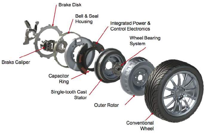
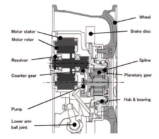
Figure 22: Section of In Wheel Motor (Murata, 2012)
The motor is structured to be high torque low speed motor. The dimension of the mounted system has be compact and precise making it challenging to compress to required size. As the entire setup is closely packed in a compact design, one of the challenges to be addressed is thermal management. The motor is capable of providing both positive and negative torque. By combining the foundation braking system with regenerative braking from the in-wheel motor, the foundation brakes can be significantly downsized. This is possible as the brake force can be distributed through the car by controlling the series regenerative braking on the individual motors. For high performance vehicles, torque vectoring can be implemented but can be quite complex and expensive. (Hilton, 2016)
Even though there are multiple concerns over the unsprung weight, simulations carried by (Schalkwyk and Kamper, 2015) show that the vibrations experienced by the occupants do not differ from normal wheels and regular suspension components can be used for in wheel motors without the need for any modifications. This has an additional benefit of retrofitting the motor in existing cars without complex modifications to the vehicle.
17.2 Integrated Electronics
Integrated power electronics are compact and their design differs from on vehicle inverters.
Traditional designs are not possible for required compact design due the need for large heat sinks and several passive components. The electronics are also exposed to environmental conditions and need to be sealed such that water, vibrations and dust do not affect them.
| On-Vehicle Inverter | Integrated Inverter |
| Easy electronics environment | Harsh Environment requiring sealing |
| High AC resistance and inductance | Low AC losses leading to low EMC |
| Complex routing of cables | Manageable routing |
| Low space constraints | High space constraints |
Figure 23: Comparison of On-Vehicle and Integrated Inverter (Fraser, 2011)
An excellent design is proposed to reduce the size of the power electronics components and to eliminate the heat sink in (Wang, 2013). This is done by replacing silicon based IGBT with wide band GaN transistors. These devices are proven to provide ultra high efficiency operation with close to 99% efficiency (Morita et al., 2011).
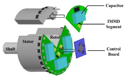
Figure 24: Integrated Modular Motor Drive (Wang, 2013)
The motors have a response time that is faster than the foundation brakes. Hence, the in-wheel motors can be implemented to work with ABS and ESP of the vehicle. There is a major safety aspect involved with having multiple motors. There need to be built in redundancies as a small fault which may cause one of the motors to shut down during high speed can have catastrophic damage. The design should ensure that a single fault should not cause the driver to lose control due to unintended braking or acceleration. Hence, these designs require high ASIL ratings, making the design complex and expensive.
18 Challenges
The primary concern for in-wheel motors is that it is a prototype design and has not yet been implemented. This design will restructure the physical design of the car by eleminitating the need for a hood. The design challenege for the in wheel motor itself is to downsize all its components to fit in the space reserved for a wheel. The speed a IWM will need to rotate at is much lower than the motor under the hood of an EV. Hence the IWM are high torque motors with gearing required for each wheel. To have a powerfull IWM expensive rare earths with high magnetic properties will be required increasing its cost. As a minimum of two IWM are required for an EV, the combined cost of the IWM,s will be much higher than a single traditional motor. Certain fundamental designs such as ABS, ESP and differentials will need to be modifies to adapt to the behaviour of an IWM almost requiring reinvention of the wheel.
Require big tyres
19 Conclusion
One of the most intriguing possibility for an EV is to fit motors inside the wheels. Although no production car is available with this architecture yet. It certainly seems to be a design for the future. Many concepts have been designed including proteam,mistibishi and Toyota which seem to be a promising design. The advantages mainly are more room and reduction of transmission losses. The cost of an IWM can be drastically reduced if the concept goes into mass production, where a common IWM can be shared throughout the different vehicles produced by manufacturers.
20 References
Akin, E., Ertan, H. B. and Uctug, M. Y. (1994) ‘A method for stator resistance measurement suitable for vector control’, 3, pp. 2122–2126 vol.3. doi: 10.1109/IECON.1994.398147.
Alexander, C. K. and Sadiku, M. N. O. (2001) Fundamentals of Electric Circuits, Organization. doi: 10.1017/CBO9781107415324.004.
Busarello, T. D. C., Simões, M. G. and Pomilio, J. A. (2017) ‘2 – Semiconductor Diodes and Transistors’, in Rashid, M. H. (ed.) Power Electronics Handbook (Fourth Edition). Fourth Edi. Butterworth-Heinemann, pp. 15–48. doi: https://doi.org/10.1016/B978-0-12-811407-0.00002-7.
Cosmol (2017) Finite Element Method based Investigation of IPMSM Losses. Available at: https://www.comsol.com/paper/finite-element-method-based-investigation-of-ipmsm-losses-51851 (Accessed: 2 January 2018).
Ehsani, M., Yimin, G. and Miller, J. M. (2007) ‘Hybrid Electric Vehicles: Architecture and Motor Drives’, Proceedings of the IEEE, 95(4), pp. 719–728. doi: 10.1109/jproc.2007.892492.
Fitzgerald, A. E. (2003) Electric machinery, Journal of the Franklin Institute. doi: 10.1016/0016-0032(85)90014-6.
Foley, M. W., Julien, R. H. and Copeland, B. R. (2008) ‘A Comparison of PID Controller Tuning Methods’, The Canadian Journal of Chemical Engineering, 83(4), pp. 712–722. doi: 10.1002/cjce.5450830412.
Fraser, A. (2011) ‘In-wheel electric motors the packaging and integration challenges’, in 10th International CTI Sympo-sium.
Genduso, F. et al. (2010) ‘Back EMF sensorless-control algorithm for high-dynamic performance PMSM’, IEEE Transactions on Industrial Electronics, 57(6), pp. 2092–2100. doi: 10.1109/TIE.2009.2034182.
Gieras, J. F. (2009) Permanent magnet motor technology : design and applications. 3rd Editio. CRC Press.
Guoqiang, C. and Jianli, K. (2010) ‘Simlation and anlysis of hysteresis current controller in motor control’, Proceedings – International Conference on Electrical and Control Engineering, ICECE 2010, pp. 4196–4199. doi: 10.1109/iCECE.2010.1019.
Gutfleisch, O. et al. (2011) ‘Magnetic materials and devices for the 21st century: Stronger, lighter, and more energy efficient’, Advanced Materials, 23(7), pp. 821–842. doi: 10.1002/adma.201002180.
Guttowski, S. et al. (2003) ‘EMC issues in cars with electric drives’, IEEE Symposium on Electromagnetic Compatibility. Symposium Record (Cat. No.03CH37446), 2, pp. 777–782. doi: 10.1109/ISEMC.2003.1236706.
Hilton, C. (2016) ‘Wheel Torque and Speed in a Vehicle with In-Wheel Motors’, (May).
Jäger, C., Grinbaum, I. and Smajic, J. (2017) ‘Dynamic Short-Circuit Analysis of Synchronous Machines’, 53(6).
Jahns, T. M. (2017) ‘The Past, Present, and Future of Power Electronics Integration Technology in Motor Drives’, CPSS Transactions on Power Electronics and Applications, 2(3), pp. 197–216. doi: 10.24295/CPSSTPEA.2017.00019.
Johnson, M. a. and Moradi, M. H. (2005) PID Control New Identification and Design Methods. doi: 10.1007/1-84628-148-2.
Krishnan, R. (2017) Permanent Magnet Synchronous and Brushless DC Motor Drives. CRC Press. Available at: https://books.google.co.uk/books?id=U-RxikH3aXEC.
Liu, K., Zhu, Z. Q. and Stone, D. A. (2013) ‘Parameter estimation for condition monitoring of PMSM stator winding and rotor permanent magnets’, IEEE Transactions on Industrial Electronics, 60(12), pp. 5902–5913. doi: 10.1109/TIE.2013.2238874.
Morita, T. et al. (2011) ‘99 . 3 % Efficiency of Three-Phase Inverter for Motor Drive Using GaN-based Gate Injection Transistors’, pp. 481–484.
Murata, S. (2012) ‘Innovation by in-wheel-motor drive unit’, Vehicle System Dynamics, 50(6), pp. 807–830. doi: 10.1080/00423114.2012.666354.
Murray, A. and Hare, B. (2002) ‘Resolver Position Sensing System With Integrated Fault Detection for Automotive Applications’, System, p. 864. doi: 10.1109/ICSENS.2002.1037221.
Musak, M. and Stulrajter, M. (2013) ‘Novel Methods For Parameters Investigation Of PM Synchronous Motors’, ACTA Technica Corviniensis – Bulletin of Engineering, pp. 51–56.
Pavel, C. C. et al. (2017) ‘Role of substitution in mitigating the supply pressure of rare earths in electric road transport applications’, Sustainable Materials and Technologies. Joint Research Centre, European Commission, 12, pp. 62–72. doi: 10.1016/j.susmat.2017.01.003.
Perovic, D. K. (2012) ‘Making the impossible, possible-overcoming the design challenges of in wheel motors’, World Electric Vehicle Journal, 5(2), pp. 514–519.
Petrov, I. et al. (2017) ‘Rotor Surface Ferrite Permanent Magnets in Electrical Machines: Advantages and Limitations’, IEEE Transactions on Industrial Electronics, 64(7), pp. 5314–5322. doi: 10.1109/TIE.2017.2677320.
Qu, R., Aydin, M. and Lipo, T. A. (2003) ‘Performance comparison of dual-rotor radial-flux and axial-flux permanent-magnet BLDC machines’, in Electric Machines and Drives Conference, 2003. IEMDC’03. IEEE International, pp. 1948–1954 vol.3. doi: 10.1109/IEMDC.2003.1210718.
Ruoho, S. (2006) ‘Demagnetisation of permanent magnets in electrical machines’, OH presentation, Helsinki University, (July), pp. 181–185. Available at: http://egdk.ttu.ee/files/kuressaare2007../Kuressaare2007_181Ruoho.pdf.
US (Dept. of energy) (2012) ‘Determining Electric Motor Load and Efficiency’.
Wang, J. (2013) ‘Evaluation and Design for an Integrated Modular Motor Drive ( IMMD ) with GaN devices’, pp. 4318–4325.
Wang, Y. and Liu, J. (2011) ‘Research on the load characteristics of permanent magnet synchronous motor’, Proceedings of the 2011 2nd International Conference on Digital Manufacturing and Automation, ICDMA 2011, pp. 2–5. doi: 10.1109/ICDMA.2011.256.
Weber, H. F. (1965) ‘Pulse-Width Modulation DC Motor Control’, Industrial Electronics and Control Instrumentation, IEEE Transactions on, IECI-12(1), pp. 24–28. doi: 10.1109/tieci.1965.229545.
Wilson, S. D., Stewart, P. and Stewart, J. (2012) ‘Real-time thermal management of permanent magnet synchronous motors by resistance estimation’, IET Electric Power Applications, 6(9), p. 716. doi: 10.1049/iet-epa.2010.0232.
Wu, S., Song, L. and Cui, S. (2007) ‘Study on Improving the Performance of Permanent Magnet Wheel Motor for the Electric Vehicule Application’, Ieee Transactions on Magnetics, 43(1), pp. 438–442.
Yang, S. et al. (2014) ‘Cost reduction of a permanent magnet in-wheel electric vehicle traction motor’, Proceedings – 2014 International Conference on Electrical Machines, ICEM 2014, pp. 443–449. doi: 10.1109/ICELMACH.2014.6960218.
Yildirim, M., Polat, M. and Kurum, H. (2014) ‘A survey on comparison of electric motor types and drives used for electric vehicles’, 16th International Power Electronics and Motion Control Conference and Exposition, PEMC 2014, pp. 218–223. doi: 10.1109/EPEPEMC.2014.6980715.
Yongdong, L., Hao, Z. and Open, A. (2008) ‘Sensorless Control of Permanent Magnet Synchronous Motor – A Survey’.
Cite This Work
To export a reference to this article please select a referencing stye below:
Related Services
View all


Related Content
All TagsContent relating to: "Electronics"
Electronics regards the science and technology involved in the development of electrical circuits and electronic devices and equipment that use them.
Related Articles

DMCA / Removal Request
If you are the original writer of this dissertation and no longer wish to have your work published on the UKDiss.com website then please: