Effect of Embedment Ratio on Load-Transfer and Failure Mechanisms of Helical Screw Piles
Info: 9421 words (38 pages) Dissertation
Published: 9th Dec 2019
Tagged: ConstructionEngineering
List of symbols and abbreviations
| Ap | area of the helical bearing plate |
| CSM | Cylinder shearing method |
| cu | undrained shear strength of soil |
| Dp | diameter of the helical bearing plate |
| Ds | diameter of the pile shaft |
| Fq | breakout factor that is applied for the cohesionless soil. |
| Hbottom | depth to the lowermost helical plate; |
| Heff | pile effective length on top of the uppermost helical plate which is normally calculated as Heff=Hemb-Dp |
| Hemb | embedment depth to the top helical bearing plate; |
| HembDp | Embedment ratio |
| Ks | a coefficient applied for the lateral earth pressure when it is loaded in compression; |
| KT | an empirical scaling factor for torque |
| Ku | a coefficient applied for the lateral earth pressure when it is loaded in tension; |
| Lcyl | length of the cylindrical shearing surface which is also the length from the uppermost plate to the lowermost plate |
| Nc | dimensionless factor for the bearing capacity in compression for cohesive soil. |
| Nq | dimensionless factor for the bearing capacity in tension for cohesionless soil |
| Nu | dimensionless factor for the bearing capacity in tension for cohesive soil. |
| Qbearing | Resistance that is developed by the helical bearing plate |
| Qcom | ultimate axial compressive capacity |
| Qshaft | Resistance that is developed by the pile shaft |
| Qten | ultimate axial tensile capacity |
| S | spacing between each helical bearing plate |
| Sf | is a factor applied for spacing ratio |
| SDp | spacing ratio |
| T | is the average magnitude of the final installation torque, which is achieved by averaging the value of the penetration distance at the end of the pile insertion equivalent to three times of the largest helical bearing plate diameter |
| ϒ’ | is the soil’s effective unit weight |
| φ | is the soil friction angle |
| α | is a factor applied for the adhesion |
| 2D | 2-dimensional |
| 3D | 3-dimensional |
 General background of helical screw piles
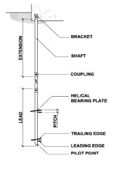
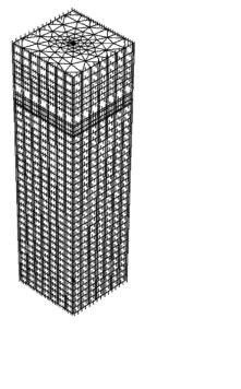
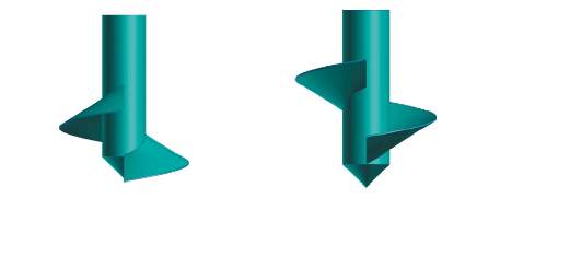
Helical screw piles are generally made of high strength steel. There are either one or more helical bearing plates attached to the pile shaft at specific spacing and a pointed toe with a 45-degree cut to facilitate the installation into the ground, as illustrated in Figure 1 (Arup Geotechnics, 2005). To minimise the soil disruption during the pile insertion, the helical plates are constructed with a carefully controlled pitch. The central shaft is typically a hollow circular steel pipe section or a solid steel square bar that is used for torque transmission during installation, transferring axial loads to the helical plates and providing structural stability against overturning and lateral forces. The screw piles are inserted into the soil by exerting rotation force using the hydraulic machine. Constant downward force is also required for advancing the downward movement of the piles. Once the installation is completed, capacities in both tension and compression will be gained for the screw piles which enable the structural loads to be transferred to the bearing stratum (Helical Pier Systems, 2010). Helical screw piles were first utilised by Alexander Mitchell, an Irish civil engineer, in the early 1800’s to support a series of lighthouses. Furthermore, screw piles were used to provide solid foundations for seaside piers and bridges over the weak and wet soil. When these piles were first developed, it required a lot of manpower to work the capstan for installation. Moreover, due to the development of steam hammer, driven piles became easier to install and reduced the use of screw piles. This situation remained until the hydraulic torque motors became available to allow easy and quick installation of screw piles (Perko, 2009). Furthermore, as the practical knowledge and engineering design continued to evolve, screw piles have become more popular. These piles allow loads to be carried in tension, compression and laterally. The current applications of screw piles include pipelines, power transmission towers, street lights and buildings foundation. Screw piles are used extensively because they offer distinct advantages over conventional piles. The advantages are as follow (Arup Geotechnics, 2005; Perko, 2009):
- Instead of using hammer to drive the piles into the ground, hydraulic torque method is used for screw piles installation which can minimise noise and vibrations significantly and lessen the impact created on the environment.
- Screw piles can be loaded immediately after installation without waiting for the concrete to cure and dissipation of excess pore water pressure.
- No drill spoil is produced which can benefit in contaminated ground.
- Since no additional equipment such as large drilled shaft rig or crane with pile hammers is required, installation is swift.
- Screw piles are a cost-effective option as they require minimal dewatering if there is a high groundwater table and they can be easily transported, removed and reused to provide temporary support to the structures.
Meanwhile, screw piles are determined to be not applicable under the soil conditions which consists of stiff or dense materials such as boulders, bedrock and cobbles. If they are installed under such situations, sustained damage to the helices may occur (Schmidt & Nasr, 2004).
It is anticipated that there is an expansion of helical screw piles into offshore renewable energy sectors. In this sector, offshore wind turbines are one of the main sustainable solutions that are highly focused by the engineers for electricity generation. Currently, monopiles are used for most of the offshore wind farms in water depths up to 30m. However, due to the increasing size of the wind turbines, they are required to be installed in areas with water depths up to 80m, which cause the deployment of monopiles in this case is cost-ineffective and multi-footing structures such as tripods and jackets will be required. Although they can carry high loads from turbines, they are found to be heavy, expensive, difficult to be transported and lifted in deep water. Furthermore, as three piles per turbines are required for tripods foundation, this prolongs the construction time and the noise pollution is created from the pile driven process. Due to concern over the impact on marine mammals, driven piling has been banned in certain areas of Europe’s regional waters (Saleem, 2011; Thomsen et al., 2006). Therefore, large-diameter helical piles are being considered as an alternative foundation for offshore structures due to the advantages of screw piles stated in Section 1.1 have the potential to overcome these issues. Since these piles are commonly used onshore and they are relatively small in scale, several aspects must be considered for the higher loading conditions for offshore structures wind turbine. Firstly, the design of screw piles in both diameter and length is required to be substantially larger than those used onshore to withstand the high loads. As the size of the piles becomes larger, higher magnitude of installation torque is necessary. To ensure the design method of the screw piles for offshore-scale can be developed safely and reliably, the process of verification of the analytical and empirical design methods with the field testing trials is required. In addition, several analyses which listed below can bring an improvement to the design method. These include analyses on (Byrne & Houlsby, 2015):
- piles behaviour under cyclic loading,
- effects that generated by a group of helical screw piles,
- response on the piles that are affected by the process of installation and remediation and
- piles stiffness.
Based on above description, it can be seen that the use of helical screw piles has considerably increased in various projects to provide high axial and lateral capacities in recent years. There is a demand of helical screw piles for more complex and efficient designs, such as application in the offshore renewable foundations which mentioned in Section 1. Currently, there are three most common design methods used for helical screw piles which include the cylindrical shear method (CSM), individual bearing method (IBM) and installation torque-to-capacity relationship. The first two methods are based theoretically, whereas the third method was developed empirically. These design methods enable the ultimate capacities of the screw pile obtained through equations (Mohajerani et al., 2016). However, these existing design methods have been shown to be inadequate, leading to under and over-conservative design approach. This is mainly due to the insufficient of full-scale field testing has been conducted which generally limited by the technical and economic issues. Eventually, it causes the load-transfer and failures mechanisms of helical screw piles cannot be fully understood by the engineers. Therefore, the application of numerical modelling has become a useful tool to provide additional insight regarding the effects of the helical screw pile loading on the vicinity soil in the full-scale field testing.
The aim of this dissertation is to develop a reliable 3D numerical model using a finite element software, namely PLAXIS 3D to investigate the effect of embedment ratio on the load-transfer and failure mechanisms of the helical screw piles under a ground that is mainly composed of cohesive soils. This investigation is performed through the estimation of their ultimate axial capacities by using several different numerical approaches.
- To apply a simple linear elastic-perfectly plastic constitutive model, namely Mohr-Coulomb model to simulate the behaviour of the undrained cohesive soils and as a first estimation for the numerical analysis.
- To calibrate the numerical model with the available field data along with several modelling approaches which include the selection of boundaries proximities, interface strength and mesh sizes.
- To validate the numerical model using the provided field cyclic tensile load testing data. This is to ensure a credible prediction of the performance of the helical screw pile can be achieved.
- To study the effect of embedment ratio by varying the depth to the top helical bearing plate and diameter of the plate accordingly using the validated numerical model.
- To identify the failure mechanism and load transfer for helical screw piles that are under compressive and tensile loadings.
- To compare the predicted ultimate capacities from the numerical and semi-theoretical method. This is to identify the applicability of the common used existing theoretical design method.
To provide a better perspective for the aim and objectives of the research continue herein, several relevant topics which consist of (1) the three different design methods, (2) some significant design issues and key parameters that influence the behaviour of the helical screw piles and (3) the available numerical modelling approaches for the prediction of the performance of screw piles are reviewed in this section.
The design methods used to predict the ultimate axial capacities named cylindrical shear method (CSL) and individual bearing method (IBM) were developed based on the identification of failure modes occur in the helical screw piles. The cylindrical shear method assumes a soil column connecting the uppermost and lowermost helical bearing plates is mobilised (Vesic, 1971; Mitsch & Clemence, 1985; Das, 1990). Whereas, the individual bearing method assumes each helical bearing plate behaves independently and the bearing failure develops at each plate (Meyerhof & Adams, 1968; Vesic, 1971). These methods generally follow the conventional Terzaghi’s general bearing capacity theory for foundation designs, but with appropriate modifications by taking account into the configuration of helical screw piles. Both methods have their respective analytical simplifications and approximations for determining the ultimate capacities.
 Cylindrical shear method (CSM)
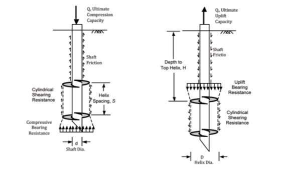
CSM is adopted when the distance between the helical plates is small. The top helical bearing plate will join with the bottom helical bearing plate and act as a group to form a cylindrical shearing surface (Mohajerani et al., 2016; Perko, 2009). In this case, the ultimate screw pile capacity is the summation of the shaft friction that is developed on the top of the uppermost helical bearing plate, resistance due to the shearing along the cylindrical surface and either the bearing resistance below the helical plate for compression or above the helical plate for tension, as shown in Figure 2.
This failure model assumes that if the spacing between each helical plate is far enough, each helical bearing plate will act individually. This also implies that the behaviour of each bearing plate would not be affected by other plates in the vicinity. In this case, the overall ultimate capacity of the helical screw pile is the summation of the bearing capacity that is developed by each individual bearing plate and the shaft friction above the top plate. However, it is noticed that the parameters affecting the ultimate compressive and tensile capacities are different, as illustrated in Figure 3. The ultimate compressive capacity of the screw piles shown in Figure 3(a) is governed by the area of each bearing plate and the undisturbed soil below the plate. Whereas, the ultimate tensile capacity of the screw piles shown in Figure 3(b) also depends by the area of 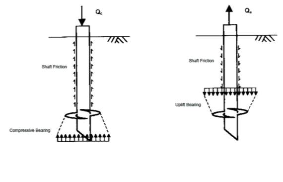 each bearing plate, but with the disturbed soil above the plate (Mohajerani et al., 2016).
An empirical method as shown in Eq (1) is commonly adopted in the modern industry. This method was discovered by Hoyt and Clemence (1989) to predict the uplift capacity of helical screw pile by making a relationship with the final installation torque. Since it was developed empirically, there was lack of geotechnical concepts to support this method. Therefore, a vast database that consists of information of more than 2500 installed screw anchors was used to perform a statistical analysis. Eventually, the result shows that this method has been applied successfully to estimate the uplift capacity for more than past 20 years in the construction industry (Hoyt & Clemence, 1989).
| Qten=KTT | (1) |
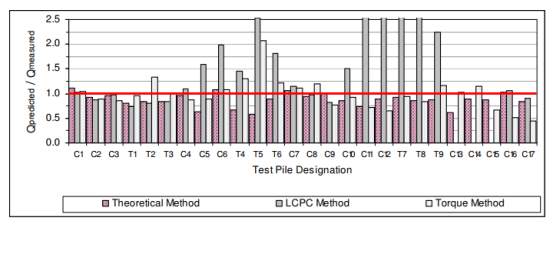
The magnitude of the final required torque to install the screw pile depends on soil consistency and strength, such as soil shearing resistance developed over the embedded area of the pile. Therefore, it is believed that an indication of the pull-out pressure and maximum bearing of the screw piles can be provided via the installation torque (Perko, 2009). Furthermore, KT suggested by Hoyt and Clemence (1989) is a constant that can only be affected by the shaft diameter of screw piles. To verify this relationship, they conducted 90 tensile load tests with different diameter of pile shafts. These tests were conducted at various sites with different soils materials including sand, silt and clay soils. The load test results were then used to compare with the estimated capacities calculated using CSM, IBM, and torque-based method. From the comparison, they concluded that the torque-based method has better precision than the cylindrical shear and individual bearing methods. Hence, this method can be used as an independent check for field verification. However, these three methods are unreliable as they over-predicted and under-predicted the ultimate capacity of the screw piles in a wide range of soil type. Investigation performed by Tappenden and Sego (2007) applying a KT factor of 9.2m-1 which is determined through the application of linear regression of the experimental data for the screw piles capacities estimation. Based on the obtained result as shown in Figure 4, they concluded that the uplift capacity of the screw pile which is installed to a shallower depth under sand condition could be over-predicted by a factor up to 2.5 times. Therefore, this method would not be used in engineering design as consultants have to back up design with insurance.
 Factors influencing the performance of helical screw piles
From the abovementioned design methods of screw piles, the capacities of helical screw piles are mainly determined based on its mode of failure. However, the suitability of either CSM and or IBM is difficult to determine as there is known to be interplay between both methods (Mohajerani et al., 2016). Based on previous research, the major contributors to the ultimate capacities of the screw piles include the disturbance of soil generated during the pile installation, soil conditions and the geometries of the screw pile such as the diameter of the helical bearing plate, spacing ratio and embedment ratio (Bradka, 1997; Mitsch & Clemence, 1985). Other than that, the shape of pile shaft, loading conditions and cyclic loading are found to have varying effects on the performance of screw piles (Zhang, 1999). Hence, these factors are discussed below to provide a better understanding on the behaviour of helical screw pile.
The embedment ratio (Hemb/Dp) is identified as the ratio of the distance between the surface of the ground and the uppermost plate to the plate diameter. This is proven to be a key factor that can affect the capacity of the helical screw pile significantly as it classifies if the pile behaves under shallow or deep condition (Zhang et al., 1998). Zhang et al. (1998) carried out experimental study including compression, tension and lateral pile load tests to understand the behaviour of screw pile in two different soil types which are sand dune and lacustrine clay. The obtained test results showed that the increase in embedment ratio generates larger ultimate compressive and tensile capacities under both cohesive and cohesionless soils.
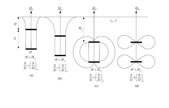
Furthermore, Rao et al. (1993) conducted an experimental programme using the pull-out test to explore the failure mechanism of multiple helical anchors that were installed in the soft marine clays at different embedment ratio which varied from zero to ten. Based on their observations, three different failure surfaces were identified at different ratios of embedment, as illustrated in Figure 5. These were then classified as shallow, transition and deep conditions. Shallow condition occurs when
HembDp≤2
, transition condition occurs when
2≤HembDp≤4
and deep condition occurs when
HembDp≥4
. As shown in Figure 5, the failure zone in shallow condition propagates to the surface and causes the formation of tension crack and surface heaving which leading to a clear gap observed between the pile shaft and the ground surface. The result also suggested that the shaft friction should not be considered in the shallow condition for the prediction of ultimate capacity. Under the transition condition, although the dissemination of the failure zone is found on the surface, the tensile cracks and surface heaving are less severe than in shallow condition. For the deep condition, no tensile cracks and surface heaving can be observed. In contrast to the shallow condition, shaft adhesion is considered for the transition and deep conditions as its contribution 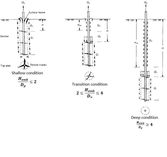 was identified in the experimental capacity.
It is noticed that the foregoing theoretical capacity calculations assume the screw piles behave in a deep mood. This allows the soil mass that sits above the top helical plate to provide sufficient pull-out resistance. Therefore, minimum embedment depth is found to be a key parameter that creates influence on the performance of screw piles. If the distance between the ground surface and the top helical plate is close enough, shallow failure can occur by creating a cylindrical shear surface between the plates and activating the wedge-shaped of soil on top of the uppermost helix. Eventually, surface crack is generated by this heaving action (Perko, 2009).
was identified in the experimental capacity.
It is noticed that the foregoing theoretical capacity calculations assume the screw piles behave in a deep mood. This allows the soil mass that sits above the top helical plate to provide sufficient pull-out resistance. Therefore, minimum embedment depth is found to be a key parameter that creates influence on the performance of screw piles. If the distance between the ground surface and the top helical plate is close enough, shallow failure can occur by creating a cylindrical shear surface between the plates and activating the wedge-shaped of soil on top of the uppermost helix. Eventually, surface crack is generated by this heaving action (Perko, 2009).
The spacing ratio (S/DP) used in helical screw pile is determined as the ratio of the distance between two helical bearing plates to the average diameter of the plates (Sakr, 2009). Rao et al. (1991) conducted load tests in the laboratory to investigate the influence of the spacing ratio and the total amount of the plates on the piles performance when they were installed to the remoulded clays. This investigation revealed that there would be a formation of a nearly cylindrical surface that encapsulates the top and bottom helical plates when the spacing ratio is 1≤SDp≤1.5 . Moreover, for screw piles that had a spacing ratio of SDp>1.5 , isolated soil plugs of soil around each helical plate can be observed which behave as individual bearing. Therefore, they concluded that failure mechanism of screw pile that changing from cylindrical shear to individual bearing happens when the spacing ratio is SDp>1.5 . Furthermore, a conclusion can be drawn from these observations was the screw piles can attain maximum capacity when they consist spacing ratio of 1≤SDp≤1.5 . Based on the observations from Rao et al. (1991), they proposed formulae to predict the load carrying capacity in both tension and compression. These formulae assume the cylindrical failure surface occurs between the uppermost and lowermost of the helical plates. These predicted values were used to compare with the experimentally obtained values. After the comparison, it was found that a good agreement occurred for the screw piles with spacing ratio of 1≤SDp≤1.5 , whereas over-prediction of pile capacity was observed for spacing ratio of SDp>1.5 . This implies that the estimated cylindrical shape of failure mechanism may only be applicable for spacing ratio of SDp<1.5 . To resolve the over-prediction of ultimate capacity at high ratio of S/Dp, a correction factor, SF, for cohesive soil was introduced by Rao and Prasad (1993), which is shown below:
| SF=1.0; forSDp≤1.5 | (2) | |
| SF=0.683+0.0693.5-SDp;for 1.5≤SDp≤3.5 | (3) | |
| SF=0.700+0.1484.6-SDp;for 3.5≤SDp≤4.6 | (4) |
Zhang et al. (1998) proved that screw piles under compression loads behave differently in cohesive and cohesionless soil through the field test results. It is found that screw piles that installed in cohesive soil yielded higher ultimate capacity with higher spacing ratio. Whereas in cohesionless soil, higher ultimate capacity was achieved with smaller spacing ratio. Hence, Zhang et al. (1998) concluded that the ultimate compressive capacity of screw piles could be improved and controlled by making an adjustment on the spacing between the helical bearing plates. On the other hand, the ultimate uplift capacity was confirmed by Zhang et al. (1998) to be independent on the inter-helix spacing in both types of soils as they obtained the same capacity with different spacing ratio of SDp=1.5 and SDp=3.0 (Zhang et al., 1998). Lutenegger (2009) presented vertical axial pull-out field tests results that were conducted under cohesive soil. Through this study, it shows that the behaviour of the screw piles is governed by CSM for spacing ratio of SDp≤2.25 , whereas IBM takes control when the spacing ratio is SDp≥2.25 . These findings are found different to the spacing ratio that determined by Rao et al. (1991). In addition, the load-displacement curve that produced by using the pull-out test results showing the screw piles behave in cylindrical shear when SDp≤3 . Meanwhile, the transition to individual plate bearing was not found which contrasts with the behaviour predicted from the analytical parametric study (Lutenegger, 2009). Apart from using both experimental and numerical technique to study the failure mechanisms that control the capacity of screw piles, Stanier et al. (2013) carried out a series of test on the small-scale physical model by adopting the use of transparent synthetic soil and particle image velocity. Through this analysis, the observation showed the cylindrical failure mechanism is dominant for the 1.5≤SDp≤3 .
 Effects on shape of pile shaft
Another factor that can affect the performance of screw piles is the shape of the pile shaft. When the square shaft is installed, adhesion can be created at the rounded corners of the shaft. This is because the void spaces that are formed between the corners have no contact to the shaft, as illustrated in Figure 6. However, to ensure the overall design is conservative, the shaft friction is typically neglected. Through the findings from Merifield et al. (2006), they concluded that higher uplift resistance could be achieved for circular anchors rather than the rectangular anchors.
Zhang (1999) reported that when multi-helix screw piles are installed in cohesive soil, the critical factor that controls the vertical capacity is the shear strength of the soil. This parameter is hard to be determined as it is dependent on the rate of loading, installation process and the type of tested soil. Under different conditions, the required parameters used for design is different. The undrained condition is considered when the pile is loaded rapidly, where the parameters determined for the soil strength will be only cohesion. When a sustained load is applied to the pile over a long period of time, it allows the pore water pressure to dissipate. Under such condition, the drained condition is applied where the required parameters to determine the soil strength will be both cohesion and frictional angle. Mitsch and Clemence (1985) studied the effect of triple helix anchors that installed in medium dense to fine sand for both undrained and drained conditions. The screw piles were installed to embedment depths ratio of four and eight which classified as shallow and deep conditions respectively. As the soil materials are considered as cohesionless which pore water pressure can be dissipated under short time, therefore, the screw piles behave similarly in both conditions and no noticeable effect from creep or plastic deformation. To understand the effect of long-term and short-term conditions in cohesive soil, Mooney et al. (1985) conducted rapid load tests and sustained load tests in the laboratory and at the field. The obtained results indicated that uplift capacities of screw piles under drained condition were approximately 20% higher than screw piles under undrained condition. However, drained shear strength from field sample is difficult to obtain and drained test for parameter determination is uneconomical to perform. As a result, undrained shear strength parameter is usually used for the axial capacity estimation in normally consolidated clay which also provide a more conservative design.
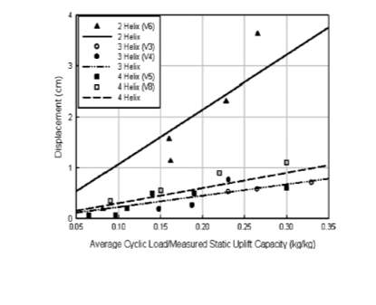
When a combination of sustained and repeated loads subject to the screw piles, it will cause cyclic loading and fatigue to occur. This can be found when they are used to provide wind resistance on the structures, such as wind turbines, communication towers and power poles (Perko, 2009). Zhang (1999) stated that the strain softening effect generated by cyclic loading is a significant concern for the piles when they are installed into soil that composed of sand and sandy silt. Adams and Radhakrishsna (1971) reported that under the stiff clay, the ultimate uplift capacities of the test footings have no significant effect on the repeated loading cycles if the cycles are within a stress range comparable to transmission-load variations. In addition, several researchers proved that the performance of the anchor and strength of the soils for both coarse and fine grain could be reduced by the cyclic loading. Meanwhile, research carried out by Clemence and Smithling (1984) showed that there was an improvement in static capacity for the repeated load application which was mainly due to the stiffening effect created by the soil-anchor system. This result can be confirmed by Cerato and Victor (2008) as they suggested that soil is compacted during cyclic loading which resulting in the capacity of the anchors increase. Other than that, cyclic load tests for helical anchors with a different number of helical bearing plates which ranging from two to four were conducted by Cerato and Victor (2008). The results showed that the anchor with two helical bearing plates tends to creep and considerably larger displacement is observed when compared to anchor with higher amount of the helical bearing plates, as shown in Figure 7.
Several studies adopted finite element method (FEM) to predict the capacity of helical screw pile through investigating the soil deformation, load-transfer and failure mechanisms of helical screw pile. FEM is a numerical method that has been employed increasingly to analyse complex geotechnical engineering problems. Appropriate use of numerical modelling not only increase the robustness and reliability on the engineering design but also save a considerable amount of cost and time that are required to perform the full-scale testing.
FEM allows the deformation patterns and distribution of stress at both the deformation and ultimate limit state stages to be captured (Laman & Yildiz, 2007). When FEM is applied, multiple iterations are performed to compute the effective stress and resulting strain at each node and each element respectively. The iterations will stop once every node and every element fulfil the relationships between the stress, strain and the boundary conditions. However, the accuracy of these approximations and estimations is highly affected by the input material properties and the model’s boundaries condition (Perko, 2009).
Perko (2009) shows the importance of an appropriate numerical modelling approach by using a FE model of a helical screw pile that was developed by Nasr (2007) as shown in Figure 8. The bottom of the model boundary is set as fully fixed which both of the vertical and horizontal deformations are not allowed. Whereas, only the movement in the horizontal direction is fixed at the side boundaries. Furthermore, the bottom and the side elements are suggested to place at a sufficient distance from the centre of helical screw pile. This is to ensure the result would not be affected by the boundaries effect. Moreover, the subsurface soil is discretised into finite elements. Each of the element has a defined Poisson ratio and stress-strain modulus to simulate the soil behaviour in the model. However, these parameters have not been commonly studied when compared to other properties of soil such as shear strength and density. The determination of the appropriate value for the soils properties that are required for a numerical model is not easy sometimes. It is suggested that the most useful way to obtain these values is through the analysis of a field load-testing programme. When the correct values that represent the soil properties are back-calculated from the numerical simulation, a parametric study regarding the effect on helical pile configurations can be performed by using the developed 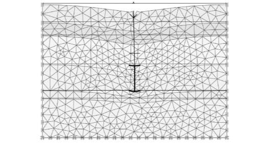 model (Perko, 2009).
(2008) created a numerical model using a software, named FLAC3D to simulate the full-scale testing of screw piles under stiff clay that was performed by Zhang (1999).
In this modelling, the elastic-perfectly plastic Mohr-Coulomb model and elastic model were adopted to simulate the behaviour of the stiff clay and the pile respectively. Interface elements were considered in the model to represent the shaft resistance. In reality, the strength of shaft friction varies along the helical screw piles. However, due to the lack of measurement was performed regarding the shaft resistance, it was assumed to be constant. When an uplift force is exerted on helical screw pile, the developed shaft resistance has a range between 0.3cu and 0.9cu (Mooney et al., 1985). This range was employed in the model to simulate the adhesion found on site. In addition, the interruption effect generated during installation that will decrease the cu of stiff clay was disregarded in the study as no relevant data given.
From the obtained results, Cui et al. (2008) confirmed that a remarkable influence on the accuracy of the result can be caused the value of shaft resistance applied in the model. It is found that the most appropriate simulation for the site can be achieved when shaft resistance was set as 0.55 cu. In addition, the load-displacement curves produced from the field test and the numerical model show that the result obtained from the model modelling starts to deviate from the field test result when the pile fails. This is due to the behaviour of strain softening and hardening of the undrained clay is not considered in the Mohr-Coulomb behaviour. Therefore, they concluded that the Mohr-Coulomb model is only suitable to evaluate the pile before failure, but not after.
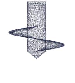
 Livneh and El Naggar (2008) conducted full-scale loading tests and developed a 3D FE model using PLAXIS 3D Foundation suite to understand how the square shaft helical screw piles transfer the load when they are under compression and tension in various soil types.
In this study, the intricacies of the geometry of helical screw piles were taking into account as PLAXIS 3D is a software that can analyse three-dimensional soil-foundation interaction realistically. The numerical model was created based on the actual scale geometry of the screw piles that used for load testing, except for the spiral section of the bearing plates which were modelled as circular discs. The vertical boundary was set at 40m below the top boundary of the model, whereas the lateral boundaries were located at 4m away from the centre of the helical screw pile. These sets of boundaries contours were used to eliminate the boundary effect on the response of the pile. The soil behaviour was described by using an elastic-perfectly plastic Mohr-Coulomb model. The essential input soil parameters including the friction angle and cohesion were obtained through prediction using the standard penetration test (SPT value) from the site and limited results from the triaxial test in the laboratory. Additionally, to increase the accuracy of the model, refined mesh was applied in the area that is near to the pile as shown in Figure 9. The soil-pile interfaces were modelled as “smooth” to control the relative displacement at the interface to a minimum. A small adjustment was made on the input soil parameters to enhance the match between the load-displacement curves that were obtained from the field and the numerical simulation.
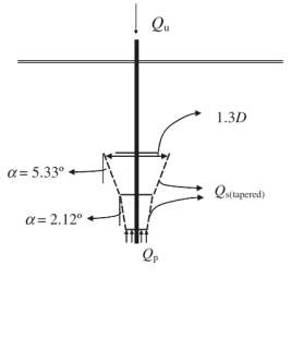
From the numerical finding, Livneh and El Naggar (2008) made a conclusion that the load-transfer mechanism from the screw piles to the surrounding soil is mainly via the cylindrical shape of the failed soil mass. The failure surface developed from the shear was found to follow the bearing capacity of the lead helix which has the identical direction as the applied load and the tapered profile of the interhelical soil profile as depicted in Figure 10. Since the overlapping between the affected soil area and the piles in the vicinity can pose an issue for the mobilisation of pile capacity, Livneh and El Naggar (2008) suggested the horizontal spacing has to be a minimum of 4D and 5D for the piles which are under compression and tension respectively, where D is the diameter of the top helix.
Livneh and El Naggar (2008) conducted full-scale loading tests and developed a 3D FE model using PLAXIS 3D Foundation suite to understand how the square shaft helical screw piles transfer the load when they are under compression and tension in various soil types.
In this study, the intricacies of the geometry of helical screw piles were taking into account as PLAXIS 3D is a software that can analyse three-dimensional soil-foundation interaction realistically. The numerical model was created based on the actual scale geometry of the screw piles that used for load testing, except for the spiral section of the bearing plates which were modelled as circular discs. The vertical boundary was set at 40m below the top boundary of the model, whereas the lateral boundaries were located at 4m away from the centre of the helical screw pile. These sets of boundaries contours were used to eliminate the boundary effect on the response of the pile. The soil behaviour was described by using an elastic-perfectly plastic Mohr-Coulomb model. The essential input soil parameters including the friction angle and cohesion were obtained through prediction using the standard penetration test (SPT value) from the site and limited results from the triaxial test in the laboratory. Additionally, to increase the accuracy of the model, refined mesh was applied in the area that is near to the pile as shown in Figure 9. The soil-pile interfaces were modelled as “smooth” to control the relative displacement at the interface to a minimum. A small adjustment was made on the input soil parameters to enhance the match between the load-displacement curves that were obtained from the field and the numerical simulation.
From the numerical finding, Livneh and El Naggar (2008) made a conclusion that the load-transfer mechanism from the screw piles to the surrounding soil is mainly via the cylindrical shape of the failed soil mass. The failure surface developed from the shear was found to follow the bearing capacity of the lead helix which has the identical direction as the applied load and the tapered profile of the interhelical soil profile as depicted in Figure 10. Since the overlapping between the affected soil area and the piles in the vicinity can pose an issue for the mobilisation of pile capacity, Livneh and El Naggar (2008) suggested the horizontal spacing has to be a minimum of 4D and 5D for the piles which are under compression and tension respectively, where D is the diameter of the top helix.
 It is noticed that the software cannot model the effects generated from the installation process correctly as the disturbed soil parameters are difficult to obtain from the site. Also, this analysis assumed the stiffness of the soil is constant throughout the depth which is incorrect in reality.
Kurian and Shah (2009) performed a numerical modelling to investigate the behaviour of the helical screw piles that are within the elastic and elastic-plastic range by considering soil-structure interaction. A constitutive model named, Drucker-Prager model was employed in this numerical simulation. Drucker-Prager model is used for cohesive materials that exhibit pressure-dependent yield which the strength of materials become higher as pressure increases (Abaqus 6.9-EF , 2009)
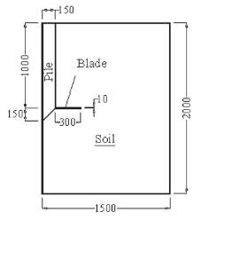
In order to reduce computational cost and time, all the researchers did not take the actual geometry of the screw piles into account, except for Kurian and Shah (2009) who consider the shape of the helical plate at a micro level using FEM, as shown in Figure 11. To eliminate the boundaries effect, the diameter and depth of the soil model as illustrated in Figure 12 were used. In the study, the soil was modelled to have a diameter of 3000m which is equivalent to five times of helical bearing plate diameter. Other studies used a soil diameter of 4500mm, and it was proven that the difference was not significant. Furthermore, soil-pile contact was represented by interface elements. Instead of using finer mesh for the whole model, it was only applied at the regions that were near to the interface elements. With this it can save the computational time and achieve relatively accurate results.
It is noticed that the software cannot model the effects generated from the installation process correctly as the disturbed soil parameters are difficult to obtain from the site. Also, this analysis assumed the stiffness of the soil is constant throughout the depth which is incorrect in reality.
Kurian and Shah (2009) performed a numerical modelling to investigate the behaviour of the helical screw piles that are within the elastic and elastic-plastic range by considering soil-structure interaction. A constitutive model named, Drucker-Prager model was employed in this numerical simulation. Drucker-Prager model is used for cohesive materials that exhibit pressure-dependent yield which the strength of materials become higher as pressure increases (Abaqus 6.9-EF , 2009)
In order to reduce computational cost and time, all the researchers did not take the actual geometry of the screw piles into account, except for Kurian and Shah (2009) who consider the shape of the helical plate at a micro level using FEM, as shown in Figure 11. To eliminate the boundaries effect, the diameter and depth of the soil model as illustrated in Figure 12 were used. In the study, the soil was modelled to have a diameter of 3000m which is equivalent to five times of helical bearing plate diameter. Other studies used a soil diameter of 4500mm, and it was proven that the difference was not significant. Furthermore, soil-pile contact was represented by interface elements. Instead of using finer mesh for the whole model, it was only applied at the regions that were near to the interface elements. With this it can save the computational time and achieve relatively accurate results.
 This numerical simulation was validated with the experimental work conducted by Rao et al. (1991). The input data of the soil properties, including the friction angle and cohesion was achieved by correlating the soil properties used by Rao et al. (1991) with the standard value that was achieved by Ranjan and Rao (2000).
Based on the finding from Kurian and Shah (2009), it can be concluded that percentage of the ultimate load in compression increase by 1719% when the diameter of helical plates increases from 300 to 900mm at zero coefficient of friction, μ, which the interface is assumed to be perfectly smooth. Furthermore, there is a 207% increase for ultimate load in tension between perfect smooth and perfect bond (no-slip) conditions with 900mm diameter helical plates. It is also observed that the ultimate compressive loads can be 301% and 117% higher when helical screw piles with a diameter of 900mm blades that given 30° downward inclination (Figure 13(a)) and 30° upward inclination (Figure 13(b)) to the horizontal respectively. However, the drawback of this analyses was the long computation time due to the shape of the screw piles which were not perfect symmetry.
Merifield (2011) employed a numerical modelling technique using displacement finite-element software, namely ABAQUS to interpret the behaviour of shallow and deep helical anchor foundation when they were installed in cohesive soils. Eventually, a practical methodology that used to design multiple helical anchors was developed.
This numerical simulation was validated with the experimental work conducted by Rao et al. (1991). The input data of the soil properties, including the friction angle and cohesion was achieved by correlating the soil properties used by Rao et al. (1991) with the standard value that was achieved by Ranjan and Rao (2000).
Based on the finding from Kurian and Shah (2009), it can be concluded that percentage of the ultimate load in compression increase by 1719% when the diameter of helical plates increases from 300 to 900mm at zero coefficient of friction, μ, which the interface is assumed to be perfectly smooth. Furthermore, there is a 207% increase for ultimate load in tension between perfect smooth and perfect bond (no-slip) conditions with 900mm diameter helical plates. It is also observed that the ultimate compressive loads can be 301% and 117% higher when helical screw piles with a diameter of 900mm blades that given 30° downward inclination (Figure 13(a)) and 30° upward inclination (Figure 13(b)) to the horizontal respectively. However, the drawback of this analyses was the long computation time due to the shape of the screw piles which were not perfect symmetry.
Merifield (2011) employed a numerical modelling technique using displacement finite-element software, namely ABAQUS to interpret the behaviour of shallow and deep helical anchor foundation when they were installed in cohesive soils. Eventually, a practical methodology that used to design multiple helical anchors was developed.
 Other than the failure modes of cylindrical shear and individual bearing, the helical screw piles were also found to fail through the shallow and deep mode of failure mechanisms (Merifield, 2011). The shallow mode of failure mechanism as depicted in Figure 14(a) and Figure 14(b) occurs if the anchors have no sufficient embedment depth, leading the soil surface to be affected. Whereas, deep mode of failure mechanism occurs when the top anchor plate is embedded into a sufficient distance from the soil surface. This deep failure mode can be divided into two types which the anchor can either fail (1) globally or (2) locally, as illustrated in Figure 14(c) and Figure 14(d) respectively. Moreover, Merifield (2011) confirmed that the failure behaviour of the anchor in either shallow or deep mode is controlled by the depth of the embedment and spacing ratio.
In the numerical analyses, the model within ABAQUS solved the problem by dividing it into two parts which are anchor and soil. Axis-symmetric analysis was applied by modelling the anchors into circular discs. The soil material was modelled as an isotropic elasto-perfectly plastic and the failure behaviour of the soil is defined by using the Mohr-Coulomb yield criterion. In reality, the introduction of shaft friction can provide extra pull-out capacity. However, this contribution which made by the shaft depends on the types of failure mechanism to the screw piles. It is found that for the small spacing ratio where the cylindrical shear method governs the failure mechanism, the effect of shaft friction is reduced. The reason is due to no relative movement between soil and shaft. Hence, the shaft friction is neglected in the analyses. Moreover, since the real soil-anchor interface has a behaviour of between perfectly smooth and rough and it was proved by Wang et al. (2010) and Merifield at al. (2003) that there is only less than 6% of difference in uplift capacity between these two cases, it can then be modelled in either conditions. In this study, Merifield (2011) modelled the interface strength as smooth. This assumes the anchors to behave as “immediate breakaway” which the tension cannot be withstood by the soil-anchor interface. In this situation, there may be a separation from the plate base with the soil beneath the interface once the load is applied. As a result, no suction or adhesion exists underneath the soil-anchor interface, where the vertical stress reduces to zero. The ultimate uplift capacity of wished in place, having circular bearing plates at varying spacing ratio and embedded to a deep condition was simulated by using small strain finite element analyses. Moreover, the failure load that the anchor cannot support was determined by applying a vertical prescribed-displacement to the anchor.
The results obtained by Merifield (2011) showed that the transformation of failure mechanism from cylindrical shear to individual bearing occurs at S/Dp=1.58. However, it is noticed that same soil strength through all depth was assumed in the analysis. This assumption is incorrect as the soil strength in reality varies with depth. It is also noteworthy that impact of the pile shaft and the installation process on the ultimate capacity was not considered in the axisymmetric analyses.
Woodcock (2012) evaluate the performance of helical screw piles in both ideally plastic soil and strain softening soil through an established 2D FE model. The actual geometry of the helical plate of screw pile was disregard and approximated as axisymmetric. Tresca failure criterion was used to analyse the soil behaviour. The strength of this criterion is independent to the normal stress but represented by the undrained shear strength (Davison & Springman, 2000). With this constitutive model, the soil was assumed to behave as ideally elastic-plastic initially and softening rule was considered at the later analyses to simulate the strain-softening effect in the undrained clay soils. Other than that, the interaction between the screw pile and the soil was considered as rough in the analyses.
Based on the findings, failure mechanism is found to be controlled by the mechanism that generated smaller capacity which is different from work done by previous researchers such as Rao et al. (1991), who stated that the failure mechanism of the helical screw pile is governed by the inter-helix spacing. Also, Woodcock (2012) concluded that the shaft stiffness of pile and brittleness index of soil are two of the critical parameters that affect the capacity of screw pile in softening soil the most. Nonetheless, the pile performance was not fully investigated as the parameters were examined independently. Furthermore, the failure mechanism, stiffness and length of piles were proved to be the most significant factors on the displacement at peak load. Piles displacement at peak load were small when they failed by cylindrical mechanism, whereas larger displacement at peak load was achieved when they failed by individual bearing mechanism. Moreover, since the behaviour of screw piles cannot be explicitly described by the number of helical plates, therefore mechanism capacity ratio is suggested as it can be used to consider the full geometry of the piles. With this, the failure mechanism of the screw piles can be predicted more accurately.
It is observed that the Woodcock (2012) ignored the process of installation in the analyses and allowed the pile-soil interface stress to follow the full stress-strain which this cannot be used for real representation. In fact, the installation of screw pile would create an impact to the interface which its strength would be reduced to residual. Hence, he provided a suggestion of using zero-thickness interface elements for future analyses to ensure the stress would not go beyond the residual strength.
Elsherbiny & El Naggar (2013) calibrated and verified the 3D numerical models using the data from a full-scale field load testing programme that were performed under sand and clay soils in Canada. The models were established by the software named, ABAQUS. Eventually, the predicted ultimate capacities of the helical screw pile from the numerical method were used to compare with the capacities that were developed theoretically. It was noticed that the ultimate capacities of the pile that had plate’s diameter larger than 620mm were obtained through the numerical modelling using a 5%Dp failure criterion.
To minimise the boundary effect, Elsherbiny & El Naggar (2013) set the radius of the soil column as 9m from the pile shaft centre which was approximately 33 times the diameter of the pile shaft, Ds. Whereas, the soil below the lowermost helical bearing plate had a depth of 4m, which is approximately 6.5Dp. The soil behaviour was depicted by using Mohr-Coulomb model where the elastic behaviour is characterised by Young’s modulus and Poisson ratio. Meanwhile, the dilation angle and friction angle were used to describe the behaviour of soil when it was under plastic deformation. The pile-soil interaction was simulated by using a penalty-type with tangential Coulomb’s friction model. This model entails that the shear force would not be transmitted until the value of the critical shear stress is achieved by the surface traction. Furthermore, an elastic model that had an elastic modulus of 200GPa and Poisson’s ratio of 0.3 was used to simulate the helical screw pile.
Based on their observation, they concluded that the ultimate capacity obtained theoretically for the pile under the sand condition was higher than the capacity estimated from the numerical modelling. Meanwhile, ultimate capacity developed from the theoretical method was observed to be consistently lower than the estimated capacity from the numerical analyses for the pile under the clay condition. From this, they asserted that the bearing capacity factor, Nc, which applied in the theoretical calculation is under-predicted. Hence, by considering the effects that generated from 3D, a value of 12 was suggested for Nc.
Other than the failure modes of cylindrical shear and individual bearing, the helical screw piles were also found to fail through the shallow and deep mode of failure mechanisms (Merifield, 2011). The shallow mode of failure mechanism as depicted in Figure 14(a) and Figure 14(b) occurs if the anchors have no sufficient embedment depth, leading the soil surface to be affected. Whereas, deep mode of failure mechanism occurs when the top anchor plate is embedded into a sufficient distance from the soil surface. This deep failure mode can be divided into two types which the anchor can either fail (1) globally or (2) locally, as illustrated in Figure 14(c) and Figure 14(d) respectively. Moreover, Merifield (2011) confirmed that the failure behaviour of the anchor in either shallow or deep mode is controlled by the depth of the embedment and spacing ratio.
In the numerical analyses, the model within ABAQUS solved the problem by dividing it into two parts which are anchor and soil. Axis-symmetric analysis was applied by modelling the anchors into circular discs. The soil material was modelled as an isotropic elasto-perfectly plastic and the failure behaviour of the soil is defined by using the Mohr-Coulomb yield criterion. In reality, the introduction of shaft friction can provide extra pull-out capacity. However, this contribution which made by the shaft depends on the types of failure mechanism to the screw piles. It is found that for the small spacing ratio where the cylindrical shear method governs the failure mechanism, the effect of shaft friction is reduced. The reason is due to no relative movement between soil and shaft. Hence, the shaft friction is neglected in the analyses. Moreover, since the real soil-anchor interface has a behaviour of between perfectly smooth and rough and it was proved by Wang et al. (2010) and Merifield at al. (2003) that there is only less than 6% of difference in uplift capacity between these two cases, it can then be modelled in either conditions. In this study, Merifield (2011) modelled the interface strength as smooth. This assumes the anchors to behave as “immediate breakaway” which the tension cannot be withstood by the soil-anchor interface. In this situation, there may be a separation from the plate base with the soil beneath the interface once the load is applied. As a result, no suction or adhesion exists underneath the soil-anchor interface, where the vertical stress reduces to zero. The ultimate uplift capacity of wished in place, having circular bearing plates at varying spacing ratio and embedded to a deep condition was simulated by using small strain finite element analyses. Moreover, the failure load that the anchor cannot support was determined by applying a vertical prescribed-displacement to the anchor.
The results obtained by Merifield (2011) showed that the transformation of failure mechanism from cylindrical shear to individual bearing occurs at S/Dp=1.58. However, it is noticed that same soil strength through all depth was assumed in the analysis. This assumption is incorrect as the soil strength in reality varies with depth. It is also noteworthy that impact of the pile shaft and the installation process on the ultimate capacity was not considered in the axisymmetric analyses.
Woodcock (2012) evaluate the performance of helical screw piles in both ideally plastic soil and strain softening soil through an established 2D FE model. The actual geometry of the helical plate of screw pile was disregard and approximated as axisymmetric. Tresca failure criterion was used to analyse the soil behaviour. The strength of this criterion is independent to the normal stress but represented by the undrained shear strength (Davison & Springman, 2000). With this constitutive model, the soil was assumed to behave as ideally elastic-plastic initially and softening rule was considered at the later analyses to simulate the strain-softening effect in the undrained clay soils. Other than that, the interaction between the screw pile and the soil was considered as rough in the analyses.
Based on the findings, failure mechanism is found to be controlled by the mechanism that generated smaller capacity which is different from work done by previous researchers such as Rao et al. (1991), who stated that the failure mechanism of the helical screw pile is governed by the inter-helix spacing. Also, Woodcock (2012) concluded that the shaft stiffness of pile and brittleness index of soil are two of the critical parameters that affect the capacity of screw pile in softening soil the most. Nonetheless, the pile performance was not fully investigated as the parameters were examined independently. Furthermore, the failure mechanism, stiffness and length of piles were proved to be the most significant factors on the displacement at peak load. Piles displacement at peak load were small when they failed by cylindrical mechanism, whereas larger displacement at peak load was achieved when they failed by individual bearing mechanism. Moreover, since the behaviour of screw piles cannot be explicitly described by the number of helical plates, therefore mechanism capacity ratio is suggested as it can be used to consider the full geometry of the piles. With this, the failure mechanism of the screw piles can be predicted more accurately.
It is observed that the Woodcock (2012) ignored the process of installation in the analyses and allowed the pile-soil interface stress to follow the full stress-strain which this cannot be used for real representation. In fact, the installation of screw pile would create an impact to the interface which its strength would be reduced to residual. Hence, he provided a suggestion of using zero-thickness interface elements for future analyses to ensure the stress would not go beyond the residual strength.
Elsherbiny & El Naggar (2013) calibrated and verified the 3D numerical models using the data from a full-scale field load testing programme that were performed under sand and clay soils in Canada. The models were established by the software named, ABAQUS. Eventually, the predicted ultimate capacities of the helical screw pile from the numerical method were used to compare with the capacities that were developed theoretically. It was noticed that the ultimate capacities of the pile that had plate’s diameter larger than 620mm were obtained through the numerical modelling using a 5%Dp failure criterion.
To minimise the boundary effect, Elsherbiny & El Naggar (2013) set the radius of the soil column as 9m from the pile shaft centre which was approximately 33 times the diameter of the pile shaft, Ds. Whereas, the soil below the lowermost helical bearing plate had a depth of 4m, which is approximately 6.5Dp. The soil behaviour was depicted by using Mohr-Coulomb model where the elastic behaviour is characterised by Young’s modulus and Poisson ratio. Meanwhile, the dilation angle and friction angle were used to describe the behaviour of soil when it was under plastic deformation. The pile-soil interaction was simulated by using a penalty-type with tangential Coulomb’s friction model. This model entails that the shear force would not be transmitted until the value of the critical shear stress is achieved by the surface traction. Furthermore, an elastic model that had an elastic modulus of 200GPa and Poisson’s ratio of 0.3 was used to simulate the helical screw pile.
Based on their observation, they concluded that the ultimate capacity obtained theoretically for the pile under the sand condition was higher than the capacity estimated from the numerical modelling. Meanwhile, ultimate capacity developed from the theoretical method was observed to be consistently lower than the estimated capacity from the numerical analyses for the pile under the clay condition. From this, they asserted that the bearing capacity factor, Nc, which applied in the theoretical calculation is under-predicted. Hence, by considering the effects that generated from 3D, a value of 12 was suggested for Nc.
 Knappett et al. (2014) contributed to the marine renewable energy sector by investigating the failure mechanism of helical screw piles under compression in sand and the critical design parameters that would influence the piles’ behaviour. This investigation was conducted through a small scale (1-g) physical modelling of screw piles, as illustrated in Figure 15, with different relative density of sands. The result obtained from the 1-g laboratory study will be used to verify the FE model by using a constitutive model that has a characteristic of stress-level dependent.
 A FEM software, named PLAXIS 2D was used to establish the numerical model. The shaft and flanges of the piles were modelled using a linear elastic solid section and elastic plate elements respectively. The interface strength between the screw pile and the soil was initially considered as relatively rough which having
δ'φ'=0.9
. However, a sensitivity analysis regarding the interface strength were performed and determined that the result would not be influenced significant by this value. The boundary conditions that were suggested by Kurian and Shah (2009) were applied to this model as shown in Figure 16. It was found that this set of boundary values can sufficiently minimise the boundary effect on pile response. Furthermore, Hardening Soil model with small-strain stiffness (HS Small) was used to describe the soil behaviour such that the response on the sand behaviour due to the small-scale model tests can be captured. The required input of soil parameters for this constitutive model was determined based on the proposed value for HST95 sand by Al-Defae et al. (2013).
Based on their findings, they concluded that a reasonable simulation of the small-scale model test was achieved through the adopted HS Small model. Moreover, S/Dp~
3 was found as an optimum value to use in screw piles design for dense sand under compression loadings. With this spacing ratio, a stronger shear mechanism developed by the soil column between the uppermost and lowermost of the plates was evident. It is also noticed that the capacity of pile becomes higher as the diameter of the flange increases. Therefore, to optimise the pile capacity for a given length, it is useful to maximise the diameter of the flanges keeps the S/Dp at 3. With this combination, the number of flanges can be reduced, resulting in a cost-effective pile for offshore structure.
Demir(2015) performed an experimental and numerical analysis to understand the uplift behaviour of helical anchors that consist of more than one bearing plate under the soft clay condition. The numerical modelling was done by using PLAXIS 2D. Cam-Clay model namely Soft Soil Model (SSM) was adopted in this analysis. This is an elasto-plastic model that simulates the non-linear soft clay behaviour under general states of stress.
In this research, the results obtained from the numerical modelling generally showed a good match with the physical modelling for the anchors embedded at different depth only at the part before the peak value occurred. Furthermore, Demir (2015) used different breakout factors, Fc, that were proposed by Merifield et al. (2003), Merifield (2011) and Singh and Ramaswamy (2008) using lower bound limit analysis, finite element analyses and model test result respectively to compare with the computed Fc from PLAXIS model. From the comparison, it shows the numerical results generating for single shallow anchor from PLAXIS give good agreement with other established methods. However, for the single deep anchor, values of breakout factor proposed by Merified et al. (2003; 2011) and Singh and Ramaswamy (2008) were overestimated and over-conservative respectively. Whereas, for multi-plate anchors in both shallow and deep conditions, the value of breakout factor increases with embedment depth ratio up to a critical ratio and it remains constant. Moreover, Demir (2015) deduced from the results obtained through PLAXIS that the transition between global deep and individual deep failure modes occurs when the critical value of spacing ratio is achieved.
A FEM software, named PLAXIS 2D was used to establish the numerical model. The shaft and flanges of the piles were modelled using a linear elastic solid section and elastic plate elements respectively. The interface strength between the screw pile and the soil was initially considered as relatively rough which having
δ'φ'=0.9
. However, a sensitivity analysis regarding the interface strength were performed and determined that the result would not be influenced significant by this value. The boundary conditions that were suggested by Kurian and Shah (2009) were applied to this model as shown in Figure 16. It was found that this set of boundary values can sufficiently minimise the boundary effect on pile response. Furthermore, Hardening Soil model with small-strain stiffness (HS Small) was used to describe the soil behaviour such that the response on the sand behaviour due to the small-scale model tests can be captured. The required input of soil parameters for this constitutive model was determined based on the proposed value for HST95 sand by Al-Defae et al. (2013).
Based on their findings, they concluded that a reasonable simulation of the small-scale model test was achieved through the adopted HS Small model. Moreover, S/Dp~
3 was found as an optimum value to use in screw piles design for dense sand under compression loadings. With this spacing ratio, a stronger shear mechanism developed by the soil column between the uppermost and lowermost of the plates was evident. It is also noticed that the capacity of pile becomes higher as the diameter of the flange increases. Therefore, to optimise the pile capacity for a given length, it is useful to maximise the diameter of the flanges keeps the S/Dp at 3. With this combination, the number of flanges can be reduced, resulting in a cost-effective pile for offshore structure.
Demir(2015) performed an experimental and numerical analysis to understand the uplift behaviour of helical anchors that consist of more than one bearing plate under the soft clay condition. The numerical modelling was done by using PLAXIS 2D. Cam-Clay model namely Soft Soil Model (SSM) was adopted in this analysis. This is an elasto-plastic model that simulates the non-linear soft clay behaviour under general states of stress.
In this research, the results obtained from the numerical modelling generally showed a good match with the physical modelling for the anchors embedded at different depth only at the part before the peak value occurred. Furthermore, Demir (2015) used different breakout factors, Fc, that were proposed by Merifield et al. (2003), Merifield (2011) and Singh and Ramaswamy (2008) using lower bound limit analysis, finite element analyses and model test result respectively to compare with the computed Fc from PLAXIS model. From the comparison, it shows the numerical results generating for single shallow anchor from PLAXIS give good agreement with other established methods. However, for the single deep anchor, values of breakout factor proposed by Merified et al. (2003; 2011) and Singh and Ramaswamy (2008) were overestimated and over-conservative respectively. Whereas, for multi-plate anchors in both shallow and deep conditions, the value of breakout factor increases with embedment depth ratio up to a critical ratio and it remains constant. Moreover, Demir (2015) deduced from the results obtained through PLAXIS that the transition between global deep and individual deep failure modes occurs when the critical value of spacing ratio is achieved.
Cite This Work
To export a reference to this article please select a referencing stye below:
Related Services
View all


Related Content
All TagsContent relating to: "Engineering"
Engineering is the application of scientific principles and mathematics to designing and building of structures, such as bridges or buildings, roads, machines etc. and includes a range of specialised fields.
Related Articles

DMCA / Removal Request
If you are the original writer of this dissertation and no longer wish to have your work published on the UKDiss.com website then please: