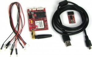
Fire and Gas Accident Avoider Using GSM Modem
Info: 7065 words (28 pages) Dissertation
Published: 11th Oct 2021
Tagged: TechnologyHealth and Safety
ABSTRACT
Fire causes huge loss of lives and properties every year in the world. Some of the main causes are insufficient fire defense materials, electric short circuit from faulty electrical wiring, presence of inflammable materials and violation of fire safety and lack of adequate awareness etc. Existing fire protection system does not work on the intensity of fire and moreover raises only alarm whenever fire is detected.
The proposed project of Fire safety is an intelligent self-controlled smart fire extinguisher system assembled with fire sensors, actuators and operated by micro-controller unit (MCU). Input signals from various sensors placed in different position of the monitored area are provided to the MCU which combines integrated microcontroller logic to identify fire breakout locations and severity. Data fusion algorithm facilitates the system to discard deceptive fire situations such as: LPG, smoke, CH4 etc. During fire hazard the proposed system monitors and controls the particular area using the inductive actuator and sends SMS through GSM to the fire service or maintenance room. Along with fire notification, also announces the fire affected locations and severity. To prevent fire from further spreading, isolation of electric circuits in the affected area will be carried out and also switch ON the ventilation and aeration fan pointing to the exact fire locations to evacuate the gas. Overall performance is evaluated through experimental tests by creating real time fire hazard prototype scenarios to investigate reliability. It is observed that the proposed system demonstrated its efficiency most of the cases perfectly.
Thus this proposed system minimizes fire hazards with fire alarm and also through SMS announces fire and also detect the severity. To prevent fire from further spreading the proposed work also incorporates isolating the electric circuits of the affected area, switch ON the gas ventilation on the hazard spot, calling fire service, and inform promptly building monitoring committee by text messages.
INTRODUCTION
1.1 Need for Fire Safety System
Fire accident causes huge loss every year in the world. Analyzing past fire incidents, facts are revealed. Some of the main causes are insufficient fire defense materials, faulty electrical wiring causes electric short circuit, presence of inflammable materials, fire safety violation and lack of awareness about the gas leakages etc. Many factories and buildings in India have proper installation and fire safety setup such as fire alarm, fire extinguishers, water supply system etc. But the argument is these conventional fire extinguishing systems are not enough to take prompt action during fire and save life. Manual system does not ensure 24/7 monitoring from fire. Moreover, existing fire system does not give the location of gas leakage or the amount of intensity in a building or factories.
1.2 Existing Fire System
Existing fire system raises only alarm whenever fire is detected at any place in a factory. Due to this alarm, people could start to run haphazardly. As a result worker in the factory get injured severely. Sometimes people do not realize the intensity of the fire and not willing to evacuate fire affected building quickly. It could lead a highly destructive.
1.3 Importance of Temperature Measurement
Temperature is an important factor in industrial and manufacturing companies like steel plants. Monitoring the temperature is a main process in industries, because a change in temperature can alter the entire manufacturing system. In existing period, there was no instrument or medium to detect the temperature. At a particular area, measuring the optimized temperature was difficult for further process. It was tough job to analyze the required temperature for proper production. As a result, industrialist suffers heavy losses. But nowadays detection of temperature has made possible at different instant of time. However, this is not sufficient for manufacturing companies, because they required continuous monitoring (24/7) for safe, secured and exact processing. This was made possible in upcoming years with the help of sensors which could continuously detect or monitor the temperature for the particular process.
1.4 Sensor Technology
The preference and development of sensor has increased which offers small dimensions, less power consumption and high reliability. Advancement of sensor technology has been boosted up by high-speed and low-cost electronic circuits which not only provide technical solutions but also improve the quality, reliability and efficiency of the products.
1.4.1 Main Characteristics of Sensor
Small size, low cost, limited processing power, low battery capacity, and short-range communications. A Wireless Sensor Networks consist of huge number of sensor nodes and is a set of hundreds or thousands of micro sensor nodes that have capabilities of sensing, establishing wireless communication between each other and doing computational and processing operations.
1.5 Motivation
The development of city gas has become an important symbol of urban modernization, but the resulting problem of gas safety using is becoming more and more serious, especially the outdoor pipeline network leakage, matter has become the priority of development of gas undertakings. Then emergencies and feasible measures and suggestions are put forward to make sure the safety operation of gas pipeline. Due to the large number of laying pipe and using for a long time, gas pipeline accidents occur frequently. So that gas sensor and fire sensor are advised to use in the industries to avoid fire accident.
OBJECTIVES AND SCOPE OF THE PROJECT
2.1. Objectives
- Detect Gas Leakage (like LPG leak, carbon-monoxide leak) or any such petroleum based gaseous substance that can be detected using MQ series Sensor.
- An SMS based Alert Mechanism and send SMS to mentioned mobile number which is given in the Arduino program
- When the fire is detected the alarm system is turned ON, the alarm get stop when the fire is under control or maintained at constant temperature.
- 16×2 LCD module will display the status.
The objectives of this fire and gas detector using Arduino is to sense the surroundings temperature with help of temperature sensor, and send SMS alerts to fire stations stored inside the Arduino program, if fire is detected using GSM Module.
2.2. Scope
The scope of the project deals with detection of gas and fire through respected sensor using a ATMEGA 328 microcontroller.
DEVELOPMENT ACCOMPLISHED
3.1 Study of Block Diagram

Fig 3.1 block diagram for fire and gas accident avoider
In the Fig 3.1 block diagram explains the industrial process parameters like temperatures and gas status are monitored remotely by using GSM communication, and thus enable to control various final control devices like drives, etc., with the use of a microcontroller.
In the transmitter section, Arduino transmitter will transmit the data to the GSM module receiver. In this safety system, the microcontroller is programmed to collect the data from an inbuilt ADC that continuously monitors temperature and 24/7 status parameters.
At the receiver side, the GSM module transmitter is connected to the Arduino receiver which will transmit the data to the Arduino receiver . In the embedded circuitry the data is transferred to the microcontroller. If the limit is exceeds by any of the parameters, then the relay driver IC receives the command signal from the microcontroller, because of this action the different loads such as motor, circuits, etc. LCD displays all these parameter information as machine human interface.by this controlling and monitoring the industrial parameters is possible through the short range low cost and low powered.
3.2 Hardware and Software requirements
3.2.1 Hardware requirements
- R3Arduino UNO
- Temperature Sensor
- Gas Sensor MQ6
- LCD
- DC Motor (FAN)
- LED / Lamp (Light)
- Driver Circuit
- Power Supply (+5V, +12V)
3.2.2 Software requirements
- Arduino IDE
- Proteus 8 Professional
3.3 Components Description
3.3.1 Arduino Uno
Arduino UNO has been used as an interfacing medium for the hardware and software. The LM35 is a temperature sensor which senses the temperature of the surrounding areas where the temperature is needed to be monitor. LM35 act as a input which transfer the surrounding temperature measurement to the Arduino. The Arduino code is done on Arduino software and burnt into the Arduino board. Once the temperature is sensed by the sensor, the data are transferred to Arduino board. The LCD shows the temperature in Celsius and fan speed.
3.3.2 What is GSM & why GSM?
GSM (Global System for Mobile) which is capable of receiving data from the surrounding and sending data over wireless medium is called GSM. The devices that provides to the wireless extends personal, household, public, business and any area that’s not affected by them now likely will be in the future. In daily life many of us see and interact with smart gadgets to our internet connected Smartphone’s, which have containing accelerometers, gyroscope, GPS and sometime heart rate monitor.
Applications of GSM
- for mobile operator
- for manufacture of smart devices
- for Banks and payment solution
- for Automobile industry
- for Airlines
- for Health
Wireless sensor network which deploy large number of sensors and data is received and transmitted to particular system for processing. There are many techniques to detect the fire. Some of those techniques include fire detection using image processing and sensors, fire detection using CCTV technology, Fire detection using zigbee.
3.3.4 Microcontrollers
The main objective of microcontroller is middle ware that sends data to system and detects fire generation or not. Microcontroller is the main part of this system. Where all the sensor outputs are given as input to microcontroller. Power supply is given to start the functions in the microcontroller. ARDUINO18f4550 has feature of inbuilt analog to digital convertor (ADC), which makes the circuit less bulky. This microcontroller transfer data to server.
3.3.5 Temperature Sensor
Temperature sensor will sense the temperature of its surrounding and send these details to the Arduino board. Here Arduino board is considered as a processing unit. Consider a constant value of temperature, whenever the sensor value is less than the constant value it will return zero else it will return one. This combination of zero and ones will be used to detect fire. LM35 is a temperature sensor which monitors the system temperature continuously and sends data to the processing unit.
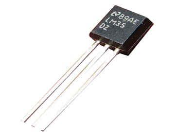
Fig 3.2 LM 35 Temperature Sensor
3.3.6 Gas sensor
Gas sensor is a sensor which detects gas which is released when fire is caused like carbon dioxide, carbon monoxide and many more. When the gases is detected the sensor will give value as one, if no particular gas is detected it returns zero. This combination of zero and ones will be used to detect fire as used in the temperature sensor.To prevent fire from spreading: some efforts are extremely important. Such as: breaking electric circuits of the affected area, releases fire extinguishing gas on the hazard spot, calling fire service, inform promptly building monitoring committee by text messages or telephone calls. The proposed intelligent system takes prompt attempt to accomplish these tasks.
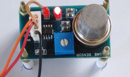
Fig 3.3 MQ-5 GAS Sensor
3.3.7 LCD (Liquid Crystal Display)
LCD screen is an electronic display module and it has a wide range of applications. A 16×2 LCD display is a basic and simple module and is widely used in various devices and circuits.
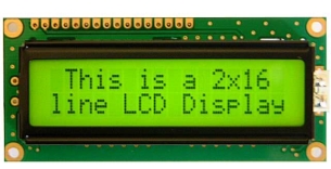
Fig 3.4 Liquid Crystal Display
A 16×2 LCD can display 16 characters in a single line and totally there are 2 lines in the display. Here each character is displayed in 5×7 pixel matrix. The two register of LCD are COMMAND and DATA. Command instructions given to the LCD are stored in the command register, the data register stores the data which is to be displayed on the LCD. The data is the ASCII value of the character to be displayed on the LCD.
The numerical, alphabets and alphanumeric character are displayed in LCD display in dot matrix and segmental displays. Nematic and Cholesteric are the two liquid crystal material which is used in display technology whose schematic arrangement of molecules is shown in fig 1.9. The Nematic Liquid Crystal (NLC) structure is the most popular liquid crystal. While retaining the complete translational freedom, the NLC molecule is align automatically which is parallel to a ordered arrangement. The NLC is normally transparent, the NLC will polarize and turn opaque when the strong electric field, disruption of the well-ordered crystal takes place. The polarized crystal will regain its original structure or original form by removal of the applied electric field and the materials become transparent.
LCD’s are classified into two types. They are,
(i) Dynamic scattering type
(ii) Field effect type.
Features of LCD
- 3-20V ac of operating voltage range.
- Slow decay time. 50 to 200 ms of response time.
- 100 degree of viewing angle.
- Invisible in darkness, so LCD requires external illumination.
- Life time is limited to 50,000 hours due to chemical graduation.
Advantages of LCD
- The required voltage is very small so that it can operate in any small voltage supplied units..
- Low power consumption. This is the important feature of the LCD module.It can operate for a long period of time by consuming very power.
Disadvantages of LCD
- LCD’s Devices are very slow. The ON and OFF times are quiet very large. Large.
- When used on DC, their life span is quite small. Therefore, they should be used with AC supplies having frequency less than 50 Hz.
Table 3.1 LCD pin descriptions
| Pin No | Function | Name |
| 1 | Ground (0V) | Ground |
| 2 | Supply voltage; 5V (4.7V – 5.3V) | Vcc |
| 3 | Contrast adjustment; through a variable resistor | VEE |
| 4 | Selects command register when low; and data register when high | Register Select |
| 5 | Low to write to the register; High to read from the register | Read/write |
| 6 | When a high to low pulse is given, the data is sends to the data pins. | Enable |
| 7 | 8-bit data pins | DB0 |
| 8 | DB1 | |
| 9 | DB2 | |
| 10 | DB3 | |
| 11 | DB4 | |
| 12 | DB5 | |
| 13 | DB6 | |
| 14 | DB7 | |
| 15 | VCC (5V) | Led+ |
| 16 | Ground (0V) | Led- |
3.4 Working description of Arduino Uno
3.4.1 Introduction
Arduino is an open source platform for prototyping based on user-friendly software. It provides a flexible base for engineers to experiment on designing interactive environments. They can be programmed for specific applications to create embedded systems which can control and sense real time parameters. It consists of a microcontroller ATmega328 which is programmed using the Arduino software.
Its main components are
- 14 digital input/output pins ( 6 can be used as PWM outputs)
- 6 Analog inputs(can also be used for digital I/O – so a total of 20 digital I/O’s)
- 16 MHz crystal oscillator
- USB connection
- ICSP header
- reset button
3.4.2 List of on-board peripherals
Table 3.2 On-Board Peripherals of Arduino
| Function | Peripheral | Pin number |
| For digital outputs: | 1 LED | 13 |
| For digital inputs: | – | 2, 3, 4, 5, 6, 7, 8, 9, 10, 11, 12, 13 |
| pulse generation & wireless communication | – | 3, 5, 6, 9, 10, 11 |
| pulse decoding & wireless communication | – | 0,1 |
| Analog sensors | – | A0. A1, A2, A3, A4, A5 |
3.4.3 The Microcontroller
The Arduino R3 comes with an ATMEGA 328 Microcontroller with an Arduino Uno Boot loader. The Boot loader facilitates the Programming of the IC from within the Arduino IDE.
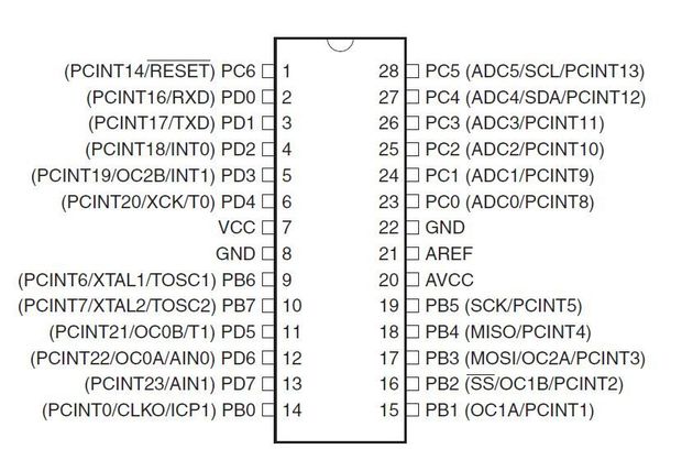
Fig 3.5 Microcontroller AT328P-Pin Diagram
Memory
Memory can be broadly divided into 3 classes:
- 32KB Flash memory –This is the storage space of the compiled program of which the boot loader uses 0.5 KB.
- 2KB SRAM – This is mainly used during run time.
- 1KB EEPROM –This is used for storing data that should not be erased upon switching off power.
Power Setup
The Arduino R3 operates at 5 Volts. It can either be powered through USB cable from the computer or through the DC jack provided on the Board.
USB Power
When powered through the USB, the 500mA Re-settable fuse on the USB power line is used to abstain the board from drawing current in excess.
USB Connectivity
Since the ATmega328 does not use USB communication directly, the need for a dedicated IC arises. FTDI FT232 IC is used to communicate between the microcontroller and USB serially .The drivers required for the Serial to USB converter has to be installed.
Hardware
The Arduino R3 / Arduino Uno Boards have 20 programmable I/O’s. They are grouped mainly as
- Pins 0 to 13
- Pins 0 to 5 [Analog Inputs 0 to 5]
Digital I/O’s
The 20 I/O’s can accept digital signals as input as well as outputs. The digital pins are numbered from 0 to 19.The Digital Pins can be used for controlling LED’s, Relays and for accepting input from Push-Buttons, Digital Sensors
Analog I/O’s
Analog inputs can be given to pins A0-A5.An inbuilt ADC Analog to digital converter is present that converts Analog voltages in the range of 0 to 5 volts to a 10-bit value. Analog sensors that sense changes in temperature or light can work with these inputs.
Analog Output
The six pins marked PWM are pins dedicated to produce Analog Output Signal. They can produce Analog voltages in the range of 0 to 5 volts with a resolution of 8-bits. They can be used for Intensity Control, Speed Control, Etc.
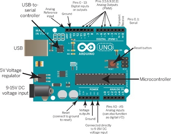
Fig 3.6 Arduino pin mapping
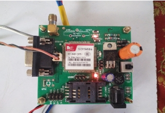
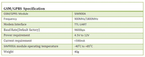
3.5 GSM/GPRS TTL UART MODEM-SIM900A
GSM/GPRS TTL UART Modem is assembled with Dual Band GSM/GPRS engine- SIM900A, GSM/GPRS TTL UART Modem works on frequencies 900/ 1800 MHz. the modem consists a interfacing voltage when the SIM card is inserted, the modem is connected to 5V & 3V3 for direct communication with microcontroller kit. The AT commands is implemented to configure the baud rate between9600-115200. The modem consists of internal TCP/IP to connect with internet via GPRS. When the TCP/IP is connected to internet via GPRS the modem can send suitable SMS, voice as well as DATA transfer application in M2M interface.
This UART modem can operate at both logic level they are TTL 3.3V logic level and 5V Logic Level, making the ARM based controller are compatible with suitable both logic level and while interfacing depending upon the controller’s logic level the voltage level differ to the Interface pin like 5V or 3.3V and the range of power to supply in the modem is between 4.5V-12V).
The SIM900A is a complete Dual-band GSM/GPRS solution in a SMT module which can be embedded in the customer applications allowing the benefit from tiny dimensions and less cost solutions. Featuring an industry-standard interface, the SIM900A delivers GSM/GPRS 900/1800MHz performance for voice, SMS, Data, and Fax in a small form factor and with low power consumption. SIM900A is compatible with these applications, especially for slim and compact demand of design.
3.5.1 Features
- Dual-Band GSM/GPRS 900/ 1800 MHz
- For direct communication with microcontroller, 3V3 & 5V interface are required.
- baud rate can be Configurable
- GSM Antenna with SMA connector.
- SIM Card holder for connecting to GPRS.
- Inherent Network Status LED
- Constitutional Powerful TCP/IP protocol stack for internet data transfer over GPRS.
- Audio interface Connector
- 4.5V-12V DC of input voltage
Table 3.3 Specification of GSM/GPRS Modem
Getting Started
Unlock the SIM card holder in the GSM module and insert the SIM card into the holder to start the module and to receive text messages to the registered mobile.
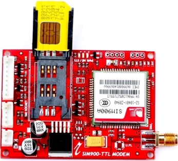
Fig 3.7 Insert an unlocked SIM card into the SIM card holder
- After that Close SIM card Holder and lock it. Both 1.8 volts and 3.0 volts SIM Cards are supported by SIM900A – the SIM card voltage type is automatically detected.
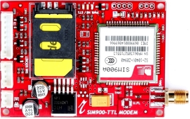
Fig 3.8 Close the SIM card holder
- Modem is assembled with the GSM Antenna
- Modem is connected to the serial cable
- Give power supply in range 4.5V – 12V through the power jack provided
- Give maximum Baud rate of 9600
- When the modem is powered-up, the Red LED on the modem (PWR) will be ON, the STS LED (GREEN) will light after 1-2 seconds and the NET LED (BLUE) will blink every second. After the Modem registers in the network (takes between 10-60 seconds), this LED will blink in step of 3 seconds.
3.6 Interface Circuit Diagram
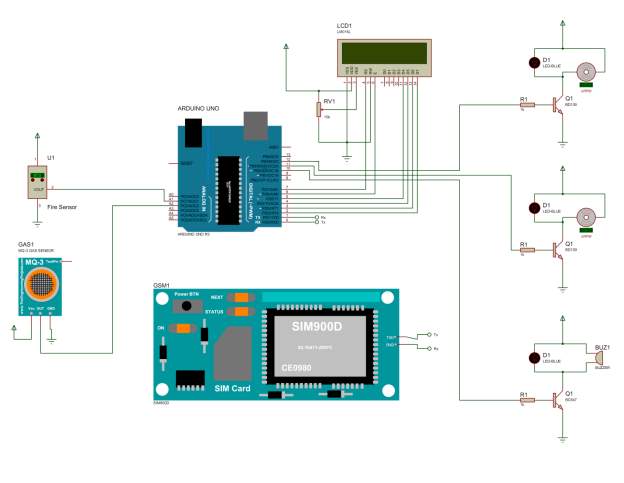
Fig 3.9 schematic representation of Fire and Gas accident avoider
Fig 3.4 shows the interface sections of Arduino with the sensor and GSM Module. In two ways GSM module to Arduino can be connected. The data are transferred from Arduino to GSM Modem. Transferring the data is always in serial. Initially connect GSM and Arduino, connect the Tx of GSM to Rx of Arduino and the Rx of GSM is connected to the Tx of Arduino. By this way the Arduino and GSM modem are connected in serial.
GSM Tx –> Arduino Rx and GSM Rx –> Arduino Tx. Then connect the ground pin of Arduino to ground pin of GSM module. These 3 connections are important to send and receive data within the Arduino and GSM. After the completion of connection load different program in Arduino to work with the GSM modem.
These are the 2 main work done by interfacing Arduino and GSM modem, they are
1) To a specified mobile number in the program, send SMS by using Arduino and GSM module.
2) The SIM card loaded in the GSM module, Receive SMS using Arduino and GSM Module.
LCD modules form a very important part in many Arduino based embedded system designs. So the knowledge on interfacing LCD module to Arduino is very essential in designing embedded systems. Interfacing an Arduino to 16×2 LCD.
Here we are using the LCD module in 4-bit mode. First, I will show you how to display a plain text messages on the LCD module using Arduino and then designed a useful project using LCD.
To control the fan speed you could reduce the drive voltage to the motor. This would be harder to do and could reduce the motor torque. PWM (Pulse Width Modulation) is easier with the Arduino and is basically like turning the motor on and off very quickly. We are turning on and off the LED inside the optocoupler which is turning on and off the transistor in the optocoupler which is in turn controlling the power transistor which is turning on and off the Fan motor. The longer the motor is on, the fast it will spin. The cycle time (OFF to ON) is very short, so short that you will not hear it occurring. Actually it occurs so fast that the fan averages the on and off times to run at a nearly constant speed.
3.7 Working description of suggested Algorithm
1) Interface GSM Modem with the controller
2) Interface GSM module to Arduino
3) Interface PWM with an Arduino-Fan speed control
4) Interface 16×2 LCD to Arduino Uno
3.7.1 Interface GSM Modem with the controller
Using hyper terminal in personal computer, check GSM/GPRS Modem:
- RS232-TTL Convertor is used to connect GSM/GPRS TTL UART MODEM-SIM900A and PC.
- Give external supply of 4.5v-12v DC to modem, then connect GSM modem with the system and make the ground supply of both modem and power supply are connected common. Likewise connect the convertor too. USB supply cannot power the modem as normal operation because it needed minimum current of 590 mA. It is better to use a power source with 1-2A current rating.
- For making connection with PC. One sample test is shown using GSM/GPRS TTL UART MODEM-SIM900A. FTDI Basic Breakout-5V is used here.
- Initially install a virtual serial port loading on the computer FT232RL drivers. After the driver installation, connect the modem, with USB/mini-USB cable, and that whether drivers are actually installed or not.
Fig 3.10 Schematic Diagram of GSM/GPRS TTL UART MODEM-SIM900A
3 ways to connect the devices, they are
- Make ground (GND-GND) common.
- TX (modem) - RX (converter TTL)
- RX (modem) - TX (converter TTL)
- In modern computers lack a hardware serial port but many embedded devices are transfer data over the serial port connection.
- To convert USB data to standard serial port data USB adaptors are used.
Fig 3.11 Schematic Diagram GSM modem connection
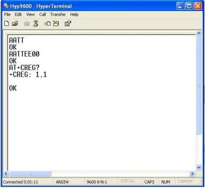
Fig 3.12 Commands to Check the SIM and Modem
- AT command (followed by enter) after “OK” command used to check that the Modem is working properly.
- ATE0 command (followed by enter) command is being used to stop the echo.
- AT+CREG (Followed by enter) command is used to check whether the SIM got registered or not.
Sending a text message from PC using AT Commands and HyperTerminal
- Let send a message using GSM/GPRS TTL UART SIM900A.
- For sending message, first send related AT commands to start the modem to send a text or messages.
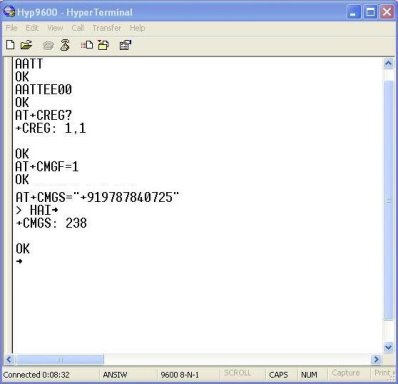
Fig 3.13 Commands to Send Text Messages
- When the command AT+CMGF=1 is implemented, then the GSM modem is sets in a SMS text mode.
- AT+CMGS=
followed by enter gives the carriage return character is represented by+z> ..
+CMGS: x and OK; where x = “number of SMS messages sent”.
3.7.2 Interface GSM Module to Arduino
Both the GSM Module and a GSM Modem (like SIM 900) are same which is connected to a PCB with different types of output taken from the board – say TTL Output (for Arduino, 8051 and other microcontrollers) and PC (personal computer) directly interfere and displays the output of RS232. The board also has pins or provisions to attach mic and speaker, to take out +5V or other values of power and ground connections. For different modules various type of provisions are made.
Booting the GSM Module
1. Insert the SIM card in the GSM module SIM card holder and close it.
2. To turn ON the GSM module, connect the power supply adapter in the GSM modem.
3. After the duration of 1 minute the ‘status LED’ or ‘network LED’ will blink. GSM module will take time to establish connection with mobile network
4. Once the connection is done with the mobile network, the status/network LED will blink every 3 seconds continuously. Try making a call to the SIM card which is placed inside the SIM card holder in the GSM modem. If a ring back in the mobile, the GSM module has successfully established network connection.
3.7.3 Interface PWM with an Arduino – Fan Speed Control
By reducing the drive voltage to the motor the fan speed is controlled. This could reduce the motor torque but this is harder to do. Arduino is easier with PWM (Pulse Width Modulation) and is simply turning the motor on and off very quickly. The longer the motor is on, the spin will be fast. The cycle time (off to on) is very short, so short cycle time will not hear it occurring. Actually cycle time occurs so fast that the fan, averages the on and off times to run at a nearly constant speed.
There are many kinds of microcontrollers are available which is very simple to program, less cost to buy, and can be built into circuits with only a few external components required.
Using an ARDUINO such as the commonly available designed for PWM output – for example, the pins labeled with a ~ on the ARDUINO board (pins 3,5,6,9,10, and 11) are PWM-enabled which means use them to control the brightness of LEDs connected. Below is a very simple circuit based around a ARDUINO board which will dim or brighten a single red LED depending on the status of the connected potentiometer dial. When the dial of the potentiometer is turned all the way anti-clockwise, +5V will go into the ARDUINO analog input pin A0. When the potentiometer is turned all the way clockwise, 0V will go into A0. Between those two limits, the voltage going into A0 will be somewhere between 0 and +5V and proportional to how far the dial has been turned back from the clockwise limit.
Pulse Width Modulation
The Pulse Width Modulation (PWM) is a superior method of dimming LEDs . With PWM strings of LED bulbs can all be driven with the recommended forward current, with the dimming achieved by turning the LEDs on and off at high frequency – so fast the human eye cannot see the strobing effect. The brighter the LEDs will appear to the observer, as long as the on periods are relative to the off periods.
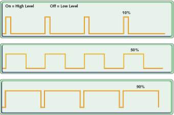
Fig 3.14 schematic diagram of Duty cycle at various percentages
Duty Cycle is a percentage measure of the time that the LED is physically on. If, for example, the LED cycles ON for 8/1000 of a second, and then OFF for 2/1000 of a second, the duty cycle is 80%: 20% of the time it is OFF, and 80% of the time it is ON. Therefore, in the undimmed level the intensity of the light will be approximately 80% as shown in Fig 3.12.
Different Output PWM Pulse
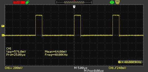
Fig 3.15 Duty cycle waveform at the speed of 20%
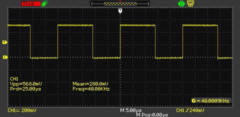
Fig 3.16 Duty cycle waveform at the speed of 45%
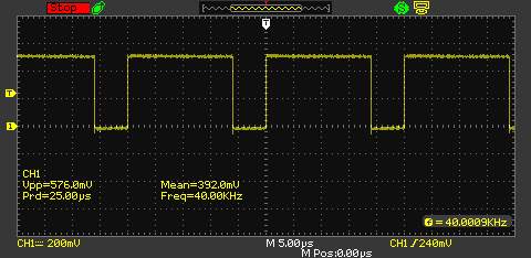
Fig 3.17 Duty cycle waveform at the speed of 65%
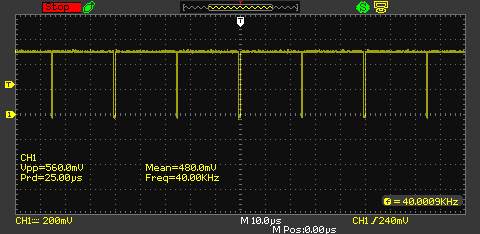
Fig 3.18 Duty cycle waveform at the speed of 85%
3.7.4 Interfacing 16×2 LCD to Arduino Uno
Interface LCD module to Arduino Uno as shown in Fig 3.17. In many Arduino based embedded system designs LCD modules 16×2 form a very important part. Interfacing LCD module to Arduino is very essential and important in designing embedded systems. LCD module used here is HD162A. JHD162A is a 16×2 LCD module based on the HD44780 driver from Hitachi.
The JHD162A LCD module has 16 pins and can be operated in 4-bit mode or 8-bit mode (using all 8 data lines). In the same way this LCD module is 4-bit mode. Initially check the LCD, by displaying a plain text messages on the LCD module using Arduino. This LCD module is connected as output from the Arduino (pin 11). Depend upon the condition in the Arduino program the LCD module display the message. Arduino receives input from sensor and it stores the data and depends upon the data the speed of the fan and temperature are displayed in the LCD module.
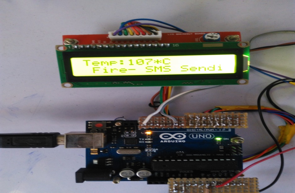
Fig 3.19 Interface LCD module with Arduino
3.8 APPLICATIONS OF SMS BASED FIRE ALARM SYSTEM
1. In remote areas SMS based Fire Alarm system are widely useful, where human commerce is limited. This kind of SMS based system is useful in mines, industrial areas, factories etc.
2. This SMS based system control and monitor the processing unit in 24/7. So the SMS based Fire Alarm system helps to monitor locations and alert during fire that occurs in night time.
3. Most of the fire damages occur due to lack of early fire detection. SMS based Fire Alert system gives messages and warning alarm immediately to multiple mobile numbers or the fire stations and hence next step actions can be taken earlier. So this helps to prevent major damages and losses created by a fire accident.
RESULTS AND CONCLUSION
4.1 Results
Fire and Gas Accident Avoider is a better way to avoid Fire accident in Industries and detect the Gas leakage within the particular area.
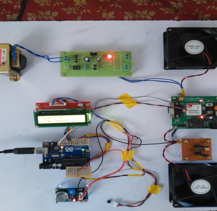
Fig 4.1 Entire Circuit connection of Fire and Gas Accident Avoider
Fig 4.1 shows the entire connection of this project, when the surrounding temperature is sensed by LM35 sensor, the sensed data is received by Arduino and display in the LCD module. The Gas sensor sense the Gas leakage from the pipeline which is received by Arduino depends upon the amount of leakage, the fan speed is controlled which is displayed on the LCD module namely 40%, 65%, and 85%. In this system one Exhaust fan and one Ventilation fan were used. To condensate the Gas from leakage Ventilation fan is used and to push out the leakage gas to the atmosphere Exhaust fan were used.
CONDITION FOR FAN SPEED
- If Temperature is
- If Temperature is == 27 then the Fan speed is increased to 20%.
- If Temperature is >= 30 then the Fan speed is increased to 40%.
- If Temperature is >= 35 then the Fan speed is increased to 60%.
- If Temperature is >=40 then the Fan speed is increased to 100%.
When the Temperature is greater than or equal to 40
4.2 Conclusion
There is an immense need of implementation of automatic fire detecting system to protect lives and assets from fire hazards. In this paper full fire protection systems are explained. Use of real-time control via the Internet or wireless network will extend the monitoring and control of fire safety systems outside of the building. The status of the fire safety system and other building systems can be monitored at any time and from anywhere via the Internet or wireless network. The fire safety systems located in many buildings will be controlled from one central facility office. This will increase the efficiency and reduce costs for building management operations, more efficiently discriminate between fire and non-fire threats and increase the time available for property and life protection. However, GSM based monitoring and control of fire safety service systems will need security protection to prevent false fire information being provided to building owners and fire brigades.
REFERENCES
[1] S.R.Vijayalakshmi and S.Muruganand, “DESIGN CHALLENGES INWIRELESS FIRE SECURITY SENSOR NODES”, International Journalof Embedded systems and Applications (IJESA) Vol.5, No.2, June 2015.
[2] Sadiccha C. Pol, Ashwini H. Wagh, Pooja T. Ramole, Smrati H. Sharma,”Fire Detection Using Image Processing and Sensors”, International Journalof Engineering Trends and Applications (I JETA) Volume 3 Issue 2, MarApr 2016.
[3] Osman S. da Penha Jr.,Eduardo F. Nakamura, “Fusing Light and Temperature Data for Fire Detection”.
[4] Jimin Cheon, Jeonghwan Lee, Inhee Lee, Youngcheol Chae, Youngsin Yoo,and Gunhee Han, “A Single-Chip CMOS Smoke and Temperature Sensor for an Intelligent Fire Detector”,IEEE SENSORS JOURNAL, VOL. 9, NO. 8,AUGUST 2009.
[5] Ren C. Luo Fellow, ZEEE, Kuo L. Su, Kuo Ho Tsai, “Intelligent Security Robot Fire Detection System Using Adaptive Sensory Fusion Method”.
[6] Kausik Sen1, Jeet Sarkar1, Sutapa Saha1, Anukrishna Roy1, DipsetuDey1, Sumit Baitalik1,Chandra Sekhar Nandi2, “Automated Fire Detectionand Controlling System”, International Advanced Research Journal in Science, Engineering and Technology Vol. 2, Issue 5, May 2015.
[7] Robert A. Sowah,Abdul R. Ofoli,Selase Krakani,Seth Fiawoo, ”Hardware Design and Web-based Communication Modules of a Real-time Multi-Sensor Fire Detection and Notification System using Fuzzy Logic”,DOI 10.1109/TIA.2016.2613075, IEEE.
[8] P. N. Narendra Reddy, P. I. Basarkod, S. S. Manvi, ”Wireless Sensor Network based Fire Monitoring and Extinguishing System in Real Time Environment”, Int. J. Advanced Networking and Applications Volume: 03, Issue:02, Pages:1070-1075 (2011).
[9] Zhigang Liu and Andrew K. Ki, “Review of Recent Development in FireDetection Technologies”.
Cite This Work
To export a reference to this article please select a referencing stye below:
Related Services
View allRelated Content
All TagsContent relating to: "Health and Safety"
Health and Safety is a set of regulations, policies, procedures, and guidelines that aim to prevent any accidents or injuries from occurring. Health and Safety procedures are essential to ensuring a safe, efficient working environment.
Related Articles
DMCA / Removal Request
If you are the original writer of this dissertation and no longer wish to have your work published on the UKDiss.com website then please:

