Design and Fabrication of a Go-kart
Info: 9248 words (37 pages) Dissertation
Published: 22nd Nov 2023
Tagged: EngineeringMechanics
DESIGN AND FABRICATION OF THE GO-KART
Abstract
Study on Rule book prescribed for go-kart, designing, fabrication and the methodology involved are studied in this paper. Through different design events, students are able to show interest towards designing and how it can be fabricated. Design of the Go-kart is based on the rules and regulations, set by the event organization, Imperial Society of Innovative Engineers, 2017(This rule book changes every year on considering the safety and innovative ideas). The Designing of the Go-kart is carried out in the SOLID WORKS and then the analysis is analyzed in ANSYS 17.0 by considering different types of materials and application of loads. Fabrication of the go-kart is performed in our University mechanical workspace. And the test drive on the go-kart is performed to check the performance of the engine, application of brakes and if any required modifications to be made.
Introduction
Go-karts may appear like little autos, yet there are some characterizing attributes that differ them from ATVs or other small auto-motives. Intelligibly, measure is a major factor, yet one noteworthy part of it is total absence of a customary suspension; here the hub is solidly appended to the edge, no differential, and keeping in mind that things like camber and caster might be customizable.
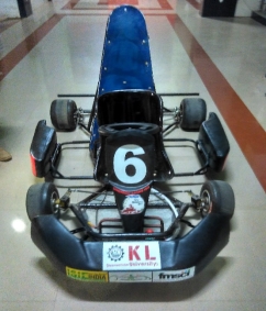
Fig.1 Go-kart
Typically, a kart has a solitary brake circle on the back and nothing on the front, and the brake pedal is arranged to one side of the kart, with the throttle on the right, constraining the driver to either learn left-foot-braking or go plunging off base. A kart ought to have an exceptionally cozy, perfectly sized seat and no belts of any sort, and considering that karts once in a while have move confines or genuine crash structures, that is starting to change. Be that as it may, regardless of conventional security highlights, karting is viewed as an extremely safe type of motorsport.
Description of the Go-kart
A go-kart is a kind of open-wheel auto. Go-karts come in all shapes and structures, from motor less models to powerful hustling machines. Numerous recreational karts can be controlled by four-stroke motors or electric engines, while hustling karts utilize a two-stroke or, once in a while, higher fueled four-stroke motors. A large portion of them are single seater yet some recreational models can oblige a traveler. In a few nations, go-karts can be authorized for use on open streets frequently alluded to as road tracks. To fabricate the complete go-kart, different parts like steering, braking, transmission systems, electrical and other innovative ideas are added to the go-kart.
Technical Specifications of Go-Kart
- Chassis Material
- Steering System
- Suspension System & Go-Kart Dimensional Configuration
- Braking System
- Tire and Wheel
- Engine & Transmission system
- Safety Materials
Step by step procedure involved in the fabrication of Go-Kart vehicle
1. Outline the rough chassis designs which can sustain more load and can distribute the loads to the entire chassis body.
2. Selection of the best chassis frame from the rough chassis body frames.
3. Designing of the selected chassis design in the SOLIDWORKS software by considering the rules and regulations that were made by the ISIE (Imperial Society for Innovative Engineers).
4. Analyzing of the designed chassis frame in the ANSYS software by considering various loads on it and by assuming different materials.
5. Fabricating prototype of the designed and analyzed chassis.
6. Cutting the chassis material based on the design dimensions considered.
7. As per design concern bending of chassis material, if necessary.
8. Arrangement of the chassis material that were made into required dimensions and welding is being performed to build the complete chassis frame.
9. Fine finishing should be processed at welded joints by grinding or buffing method.
10. Applying grease to the entire chassis frame, after welding is completed.
11. Mounting necessary mounts for the steering, transmission and braking systems.
12. Assembling of different systems like steering, transmission and braking.
13. Fixing firmly the bucket seat, firewall, bumpers and floor closeout to the chassis frame.
14. Assembly of tires to the Go-kart.
15. Fastening of all components with lock nuts.
16. Several trial runs are performed to make sure that fabrication of the go-kart is made perfectly.
17. Finally go-kart vehicle is ready to race.
Block Diagram
Study of Rulebook


Design and analysis of the chassis body
Theoretical Calculations


Design and analysis of the chassis body
Brakes
Transmission
Steering


Ordering necessary material
Arrangement of necessary material


Fabricating Chassis Frame
Assembly of Steering, Transmission and Brakes

Assembly of Bucket seat, Firewall and Floor close-out
Trail runs of the Go-kart kart
kart
Required modifications, if necessary
Go-kart is ready to go
Block Diagram of procedure involved in fabrication of go-kart
Team Formation
A Team is required to start the design and Fabrication of the go-kart, in a short period of time with adequate knowledge in design and fabrication process involved in the manufacture of go-kart. The team strength must be a maximum of 25 members. The team members should be in a way that they must divide the work and should be regular to work with interest.
Division of Work
As per the rules mentioned from the rule book a team must comprise of 25members. According to the specified rule the team members are divided 5members into each group with respect to their areas of work interest. Division of work is to breakdown of the work into groups from a team and complete the work in a low period of time and with high efficiency, the work will be completed in short period.


1. Fabrication process involved in go-kart
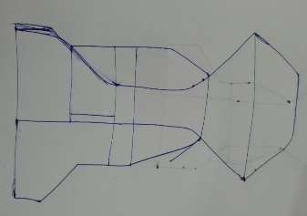
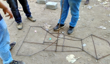
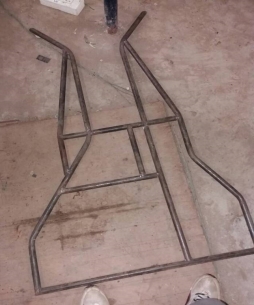
The Team members studied and analyzed the chassis designs of go-kart by considering what are the loads acting on the chassis frames and the parts attached to the chassis. Thereby designed the outline of the rough chassis designs and analyzed them in software to get the Standard chassis body.
Rough Chassis Deign 1 Rough Chassis Design 2
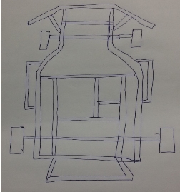
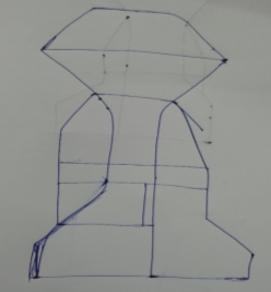
Rough Chassis Design 3 Rough Chassis Design 4
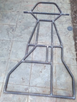
Selected Rough Chassis Design Frame:
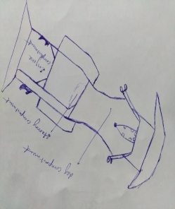
Roll Hoop
Roll hoop is placed between the engine compartment and the driver compartment. The Firewall sheets are attached to the roll hoop. The roll hoop should be placed at a distance of 2-3 inches from the seat and engine should be placed at a distance of 1-2 inch from the roll hoop. According to it the roll hoop should be adjusted on the chassis body with an inclination of 5-10° towards the engine. Height of the roll hoop should have a clearance of 3-5 inches from the top end of the driver helmet.
Bumpers
The bumpers should be placed at the front, rear and sides of the kart. The bumper material should be seamless pipes or fiber materials to cover the chassis body from all the angles. The bumpers should not allow the chassis body to deform during the accidents. The bumpers should take the max load during the accidents.
Driver’s leg compartment
The Driver leg compartment should be adjusted according to the driver comfortability of seating and his leg space for throttling and during application of brakes. Foot guard must be placed to protect the foot of the driver during accident or during collision with other kart.
Driver’s Seat compartment
Driver seat must be rigidly fixed to the chassis body. The driver seat must be positioned in an inclination according to the comfortability of the driver, so that the driver will not have back pain during riding of the go-kart. The driver seat must be bucket seat and there will be no seat belts present. Driver compartment should be arranged in a way that the driver should come out of the kart within 5 seconds during egress test.
Engine Compartment
The engine must be placed in the engine compartment in a way that it should be in diagonal to the driver seat arrangement to reduce the roll over effect of the vehicle. Engine compartment will have the engine, battery, transmission system, transmission shaft, sprocket and disc brake connected to the transmission shaft.Taking consideration of all the parts we should design the engine compartment.
Suspension system
There is no suspension system because the ground clearance of the go-kart is max 2 inches.
Wheel base
Wheel base of the go-kart is defined as the distance between the Centers of the front and rear axle tire. As per the rulebook of 3rd IKR, go-kart should have wheelbase of min 44 inches.
Track width
Track width of the go-kart vehicle should be min 75% of the wheelbase. Track width is the distance between the centers of the either front tires or rear tires.
Ground clearance
The go-kart should have a minimum ground clearance of about 2 inches. It is distance or gap between the lowest point of chassis to the ground.
Weight of the Go-kart
The weight of the go-kart is the important aspect in designingchassis body. The go-kart should be a light vehicle to achieve the max speed in race track. The go-kart total weight should be less than 165kg without the consideration of driver.
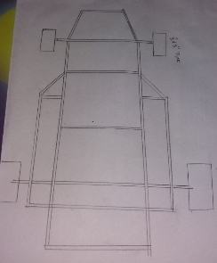
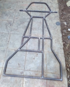
Prototype of Selected Chassis
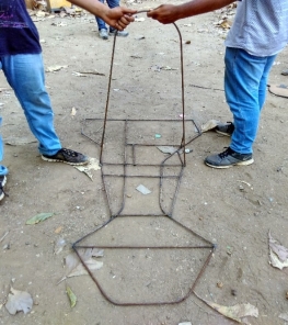
Front View
Side View
By considering the above parts and restrictions the fabrication of the go-kart chassis should be processed.
Design of Go-kart vehicle and analysis
The primary goal is to design a vehicle that is practical and easy to use yet obtaining high performance. The team is separated into individual departments: Frame and Structural, Materials Testing, Safety, System Integration, Administration and Finance. Each design department is responsible for their respective aspect of the design, except for System Integration. The specific task of the system integration department is to ensure a cohesive design for which they necessitate checking for clearance issues, certain part requirements, and overall ensured everything would come together perfectly.
Design process after selecting various systems to be designed and alternatives to those systems by modeling them in CAD software’s like Solidworks, Catia and Analysis was carried out in Ansys Workbench. After obtaining results of analysis, if any constraints were found we have gone for re-modeling and the systems or components were retested and the constraints were rectified. This design process is iterative and is based on various engineering and reverse engineering process depending on the availability of material, cost and all the parameters that are to be considered during selection of material. Our design mainly focuses on the strength, durability, safety, driver comfort, and pleasing look of the vehicle. To achieve the best design we have divided the design team into groups as mentioned below.
1. Modeling
Design Specifications:
| Roll cage/chassis | |
| Weight | 22 kg |
| Material | AISI 4130 |
| Outer diameter | 25.4mm |
| Thickness | 2mm |
| Vehicle Dimensions | |
| Ground Clearance | 2” |
| Wheelbase | 46” |
| Back Track width | 44” |
| Front track width | 42” |
| Overall Length | 68” |
| Overall Width | 48” |
| Height of RPS | 40” |
Table: vehicle specifications
Considerations:
| Consideration | Priority level | Validation |
| Weight | 1 | Light in weight kart gives best output |
| Durability | 1 | Material shouldn’t deform at span of time or condition |
| Cost | 4 | Cost is the deciding factor as kart should be within budget |
Table: vehicle considerations.
Software’s used:
| PURPOSE | SOFTWARE EMPLOYED |
| 2-D Model | AUTOCAD |
| 3-D Model | Solid Works Assembly Module |
| Structural Analysis | ANSYS Workbench |
Table: software’s used.
CAD model of chassis
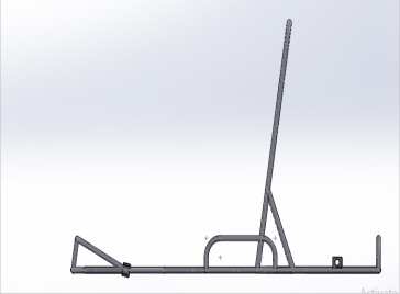
Figure: side view
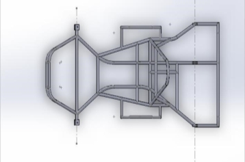
Figure: Top view
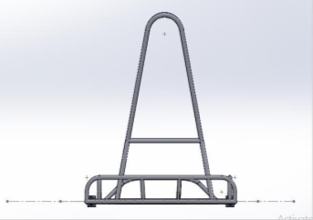
Figure: Right view
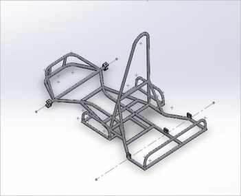
Figure: isometric view
2. Analysis
Material: AISI 4130
Material properties:
| Ultimate tensile strength (Mpa) | 655 |
| Ultimate yield strength (Mpa) | 415 |
| Bulk modulus (Gpa) | 140 |
| Shear modulus (Gpa | 80 |
| Elastic modulus (Gpa) | 210 |
| Poisson’s ratio | 0.3 |
| Brignell’s Hardness | 197 |
| Density (g/cc) | 7.85 |
Table: material properties
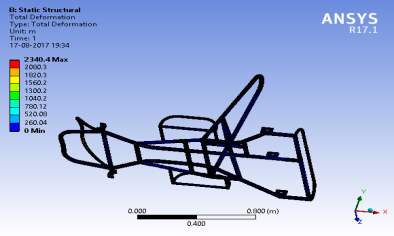
Roll-over protection Analysis
The load applied is 5000N at 10 degrees with the vertical onto the top roll member such that it is distributed over the length.
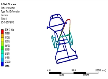
Figure: – load on RPS
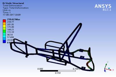
Analysis of chassis: At seating position
The load applied is 3000N
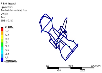
Figure: – load on seating position
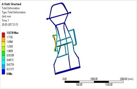
Figure: – load on side bumper
At front bumper
Front impact was calculated for and optimum speed of 60 kmph. From impulse momentum equation, 5g force has been calculated. Time of impact considered is 0.2 seconds as per industrial standards. F x t = m x (Vi – Vf), F x 0.2 = 180 x (17 – 0) => F approximately equal to 15 KN.

Figure: – load on front bumper.
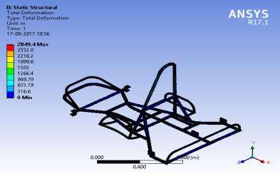
At back bumper
Back impact was calculated for and optimum speed of 50 kmph. From impulse momentum equation, 5g force has been calculated. Time of impact considered is 0.3 seconds as per industrial standards. F x t = m x (Vi – Vf) , F x 0.3 = 180 x (14 – 0) => F =8.4 KN
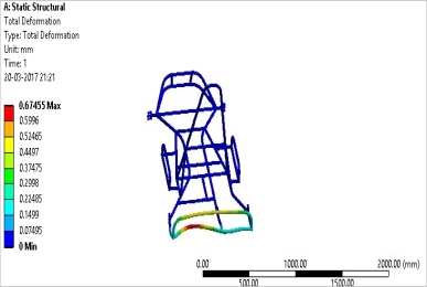
Figure: – load on back bumper
| S. No | Nature of Load | Load (N) | Stress(MPa) | Factor of Safety | Deformation (mm) |
| 1 | Roll over protection | 2500 | 646.09 | 1.15 | 6.56 |
| 2 | Seating position | 3000 | 582. 11 | 1.7 | 4.6 |
| 3 | Side bumper | 8400 | 911.24 | 1.2 | 1.92 |
| 4 | Front bumper | 10000 | 359.11 | 1.15 | 1.22 |
| 5 | Back bumper | 8400 | 336 | 1.23 | 0.67 |
Table: roll cage Analysis results
The chassis is designed in such a process that it should steer safe and the jade that applies does not change the structural strain of the chassis. The chassis is the backbone of the kart as it has to be malleable so that it must be equal enough to the suspension. Chassis construction is normally of a tubular interpretation, necessarily GI with different grades. In this kart, we consider ASTM A29 i.e., AISI 4340 material. The chassis supports the capability unit, power enable, the running system etc.
The impact forces acting on the chassis body:
i) Front Impact
ii) Rear Impact
iii) Side Impact
FRONT IMPACT
Front impact
REAR IMPACT
Rear impact
SIDE IMPACT
Side impact
Ergonomics and Safety
The seat in this kart is designed to be very light and is made of plastic material called as bucket seat. It is connected to the suspension by four indicates alongside elastic shrubberies lessen vibration to build driver’s solace. The pedal position is ergonomically good with the driver’s driving style. This kart has reduced cockpit which is agreeable yet sheltered. The guiding wheel is outlined to involve less space and simple to control. The off button which is mounted close to the front side of seat is in simple entry to the driver if there should arise an occurrence of crisis. Raise move circle is fused keeping in mind the end goal to secure the driver in the event of rollover of kart. The fire extinguisher on right side of driver clamped near to firewall in order to protect the driver in case of fire accident. The following figure shows the driver’s sitting posture in the go-kart.
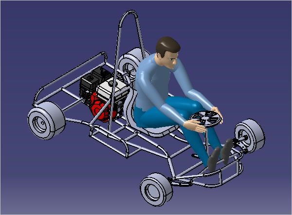
Figure: 2.6- Isometric view
Fabrication of Go-kart chassis body
The ordered material is galvanized in order maintain rust free from it. And on completion of all the design considerations and ergonomics, the prototype is made by the industrial rods. And after the prototype is completed and everything is set then it comes to the following procedure to be done. Before these procedures safety is important for fabricating the go-kart.
Safety Precautions to be considered while doing these operations
During cutting, grinding and welding safety precautions are must to be taken such that we can reduce accidents, such as;
- Putting on safety hand glouses, putting on the half handed lab dress and wearing fully covered glasses for eyes during the cutting process.
- In Welding process, welding gun should be properly handled, wear weld suit and the shield must be important to protect the eyes from strain due to high beam of rays during welding process and to see the weld path.
Cutting:
Add cutting of material pic
According to the design made the dimensions are taken. All the members are not being cut some of them are gone through bending and rest of them come here. The cutting of the material is done using the hand cutter machine. With respect to the design made the angle of cutting seamless pipe depends on it.
45°, 60° and 90° angles were some of them we used in cutting the material.
Grinding:
Same pic with grinding of welded material and on cut material
After cutting the material we can find the sharp edges to make those fine and smooth the bring operation is done. And it is also done after the welding for getting fine finishing at the weld joints. This process of smoothening the rough surface and removing the unwanted material to get a fine appearance after the welding is said to be grinding.
Bending:
Bent part material pic
Bending of the chassis material is done firmly where the material is placed between two rollers of different radii, one end is fixed and on the other end load is applied to bend the material up to the required angle that has been marked.
Welding:
Welding pic with safety in every pic
Welding is a manufacture or sculptural process that joins materials, typically metals or thermoplastics, by causing combination, which is unmistakable from bring down temperature metal-joining strategies, for example, brazing and patching, which don’t soften the base metal. Notwithstanding liquefying the base metal, a filler material is normally added to the joint to shape a pool of liquid material (the weld pool) that cools to frame a joint that is generally more grounded than the base material. Weight may likewise be utilized as a part of conjunction with warm, or independent from anyone else, to create a weld. Welding likewise requires a type of shield to ensure the filler metals or softened metals from being sullied or oxidized.
Types of welding:
1. Oxy-fuel welding
2. Shielded metal arc welding (SMAW)
3. Gas tungsten arc welding (GMAW)
4. Flux-cored arc welding (FCAW)
5. Submerged Arc Welding (SAW)
6. Electro slag Welding (ESW)
7. Electric Resistance Welding (ERW)
For our manufacturing process of kart we used the Gas Tungsten Arc Welding (GMAW) because every welding process has constraints due to the type of material used, thickness and chemical properties.
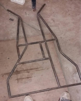
Fabrication of Chassis Design
Fabrication of chassis is developed by welding all the cutting and bending material according to the chassis design. The final input of the chassis design is taken by the lengths according to the design modified in the SOLIDWORKS.
Fabricated Chassis body
2. Steering System
2.1 Steering system
Mechanical steering mechanism of any type can be used (Rack and pinion/steer-by-wire is excluded). The steering wheel must be mechanically connected to the wheels. All parts of the steering system (steering column, tie rods, spindles (stub axles)) must be of metal.
Steering is the assortment of elements, linkages, and so on. That allows any car to follow the required course of direction. The mechanism need to have an effect on at least 2 wheels and should have agreeable steerage stops placed either on the uprights or at the rack.
Manual steering structures:
- Steering wheel and steer column;
- Linkages, steerage knuckles and ball joints;
- Wheel spindle assemblages.
Considerations:
| Factor | Priority Level | Validation |
| Simple Design | 1 | Minimize Weight To Increase Power |
| Low Steering Ratio | 3 | For Quick Steering Response |
Table: vehicle specifications
Steering wheel
The steering wheel can be taken of any diameter of different shapes. As per our IKR 3.0 rule book, the organizer needed a circle or oval shaped steering wheel with outer diameter 10 inches.
For elliptical steering wheel: Major axis diameter of 10 inches and minor axis diameter of 8 inches.
Allowable steering free play is limited to 7° total measured at the steering wheel.
Steering Column and Stub Axle:
The primary function, of steering column, is to transmit the turning moment of the steering wheel to the track rods. Therefore, steering column convert the rotary movement of the steering wheel in driver’s hand into the angular turn of the front wheels on road.
| Item | Dimensions (Inches) | Qty. |
| Steering wheel diameter | 10 | 1 |
| Steering column | 18 | 1 |
| Tie rods | 15 | 2 |
| Spindle brackets | 3 | 2 |
Table: steering components
Front Axle
Front axles are analyzed against the axial load of tie roads that were placed on the port of tie rod joint to the front axle while steering is on work. The material used for the axles is ASI-4140.Theoretically calculated load of 600N forces were placed on the axle in which the stress generated is under the safe mode and the factor of safety obtained is 2.5. Hence the overall analysis shows that the axle would be safe while working on the specified load conditions.
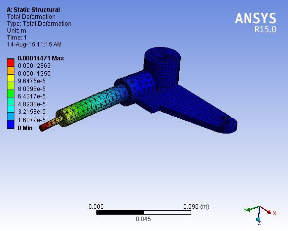
Figure: Structural analysis of stub axle.
Steering lock
The steering lock must be provided to the go-kart to steer the wheels up to a certain limit because over steer may lead to the contact of the chassis body with the wheels. So, steering locks are added to the steering system to steer the wheels in a particular angle up to a certain limit. While adjusting the steering locks we must also consider the turning radius of the go-kart.
Geometry parameters involved in Steering:
Camber angle:
Camber point is the edge made by the wheels of a vehicle; particularly, it is the edge between the vertical pivot of the wheels utilized for controlling and the vertical hub of the vehicle when seen from the front or back. It is utilized as a part of the plan of guiding and suspension. On the off chance that the highest point of the wheel is more remote than the base (that is, far from the pivot), it is called positive camber; if the base of the wheel is more distant than the best, it is called negative camber.
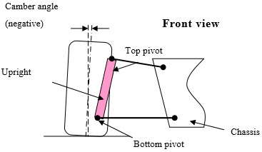
Camber.
A minor amount of positive camber of up to 7 degrees it is suggested in order to induce camber thrust.
Caster angle:
The caster edge is the precise dislodging of the guiding hub from the vertical pivot of a controlled wheel in an auto, bike, bike or other vehicle, estimated in the longitudinal course. It is the point between the rotate line (in an auto a nonexistent line that goes through the focal point of the upper swiveling appendage to the focal point of the lower swiveling appendage) and vertical. Auto racers once in a while alter caster edge to streamline their auto’s taking care of qualities specifically driving circumstances.
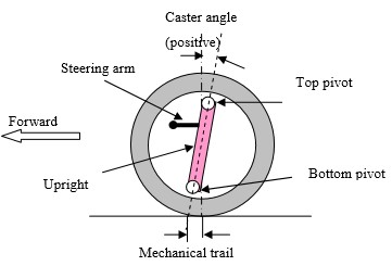
Caster.
Positive caster induces a self-correcting pressure that offers immediately line balance, but will increase steering effort. Caster ranges from approximately 2 degrees in racing vehicles up to 7 degrees.
Kingpin inclination
Kingpin inclination is the main joint in the steering system of a go-kart. It connects the steering mechanism and the spindles connected to the wheels to the chassis body.
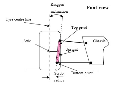
Kingpin inclination
Steering Calculations:
| Item | Dimensions (Inches) | Qty. |
| Steering wheel diameter | 10 | 1 |
| Steering column | 18 | 1 |
| Tie rods length | 19 | 2 |
| Spindle brackets | 3 | 2 |
Geometry parameters involved in Steering:
| Term | Degrees |
| Camber | 7 |
| Caster | 13 |
| Kingpin inclination | 11 |
| Toe-in | 6 |
Ackermann steering
Ackermann guiding geometry is a geometric plan of linkages in the controlling of a go-kart intended to take care of the issue of wheels within and outside of a swing expecting to follow out circles of various radii. A basic estimate to consummate Ackermann controlling geometry might be created by moving the guiding turn indicates internal so as lie on a line drawn between the directing bosses and the focal point of the back pivot. The directing turn focuses are joined by an inflexible bar called the tie pole. With consummate Ackermann, at any edge of directing, the inside purpose of the majority of the circles followed by all wheels will lie at a typical point.
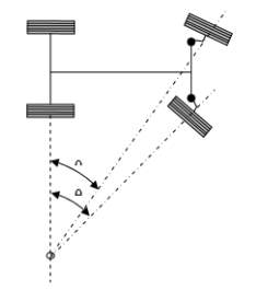
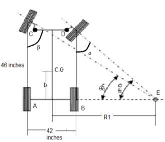
Consider Ackermann principle
b = 20.5 inches (distance from the rear wheel to the Centre of gravity)
w = wheel base = 46.2 inches
t = track width = 42 inches
Consider α = 35 degrees
From triangle CBE
Sum of angles in a triangle = 180 degrees
90 + 35 + θi =180
θi = 55 degrees
From triangle CBE
Consider BE = “x” distance
Tan θi = opposite side / adjacent side = 46.2 / x
x = 32.3529 inches.
AE = AB + BE = 42.6 + 32.352 = 74.952 inches
From triangle ADE
Tan θo = opposite side / adjacent side = 46.2/74.952
Θo = 31.64°.
Therefore θo°°
Turning radius with respect to Centre of gravity
From Fig.5.2
R1 = x + (42.6 / 2)
=53.652 inches
b = 20.5 inches
R=
Fd = the force applied to the pedal pad by the driver.
L1 = the distance from the brake pedal arm pivot to the output rod clevis attachment.
L2 = the distance from the brake pedal arm pivot to the brake pedal pad
Fd = (80÷4) ×9.8= 196N
L2 =6.35cm =0.0635 m
L1 =2.35cm =0.0235m
Fbp =196× (0.254÷0.065)
Fbp = 529.61N
Pedal Lock
Positive pedal lock should be placed to stop the pedal from free motion.
Brake Over-Travel Switch
Brake over travel switch is used to stop the vehicle. If the functioning of the brakes fails, the pedal over travels and push the kill over travel switch to stop the go-kart.
Brake light
Brake light is used to expose the vehicles behind you that the kart is slowing down. The brake light should be visible up to 10m of distance.
Braking Calculations:
Disc Specification: – pulsar 150(rear disc) – 160mm (dia) – 4 mm (thickness)
Dot 3 Fluid
Weight of Go-Kart – 185 kg
Rear Disc – 160 mm
Master Cylinder Diameter – 10 mm
Caliper Piston Diameter – 33.02 mm
Stopping Distance – 1.26 m
Stopping Time – 0.228 s
Gross Weight of the Kart: W = 185 * 9.81
= 1814.0 N Brake Line Pressure:
Force on the brake / Area of the Master cylinder
= 6.74 N/mm2 Clamping Force:
Brake line pressure * area of caliper piston * 2
= 11549.04 N Rotating
Force:
Clamping Force * No. Of brake pads * Coefficient Friction of pads = 6929.42 N
Braking Torque=Rotating Force * Effective Disc diameter
=1108.70 N-m
Braking Force: (Braking Torque / tire diameter) * 0.8
= 3175.51N
Deceleration: F = – m*a
a = -17.15 m/s2
Stopping Distance: 2 − 2 = 2 ∗ ∗
V = 0; u = 11.1 m/s (Assume initial speed u = 40kmph)
−(11.1)2 = 2 ∗ (17.15) ∗
S = 3.59 m
By considering friction of road
Assuming friction coefficient =0.8
S=3.59×0.8
S= 2.872 m
Stopping time: v = u + a * t t = 0.6472 sec.
Analysis on disc:
Analysis of break mount-The mount for the brakes was tested using the 3D stress analysis in ANSYS. The base of the mount was fixed, and a 110 lb. force was applied to the two bolt holes. The result is shown in figure. The maximum deformation that occurred in the stress analysis was .002mm at the highest point on the mount, which is negligible hence will not affect the design of the brake mount Analysis of break disc-The break disc is also analyzed in thermal module of ANSYS software in which the disc is analyzed by placing the boundary conditions as temperature, convection and coefficient of thermal expansion the total heat flux is calculated during the process as well as the heat generation. The results of disc analysis are shown in below figure.
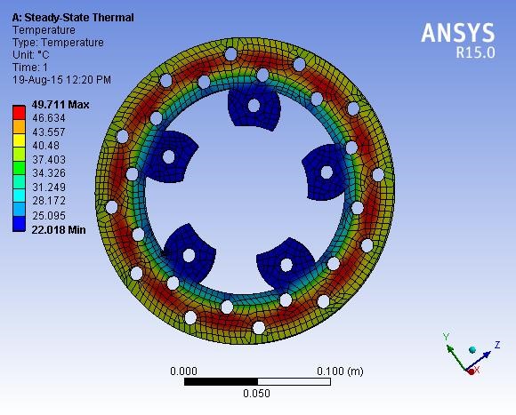
Figure 4.1: Thermal analysis of Disc
CONSIDERATIONS
| Factor | Priority level | Validation |
| Performance | 1 | Should be able to stop the vehicle at any speed |
| Light Weight | 3 | Prevents formation of air bubbles in lining |
| Reliability | 1 | Minimize the overall weight of vehicle |
| Ergonomics | 1 | Should be suitable to all the persons |
Table: vehicle consideration.
Essential-1; High-2; Desirable-3; Low-4
The following table gives the details of the brake calculations:
| Disc outer radius | 80mm |
| Disc inner radius | 40mm |
| Disc thickness | 4mm |
| Stopping time | 0.6472 sec |
| Stopping distance | 2.872mts, µ=(0.8) |
Table: brake calculations
Tire and Wheel
Tire: A tire (American English) or tyre is a ring-shaped component that surrounds a wheel’s rim to transfer a vehicle’s load from the axle through the wheel to the ground and to provide traction on the surface traveled over.
Wheel: A wheel is a circular component that is intended to rotate on an axle bearing.
| Type | Category | Dimensions | |
| Dry(slick)tires | front | D1 | 4.5 * 10.0-5 |
| Wet tires | front | W1 or W2 | 4.5 * 10.0-5 |
| Dry(slick)tires | rear | D1 | 7.1 * 11.0-5 |
| Wet tires | rear | W1 or W2 | 6.0 * 11.0-5 |
Table: tire details as per rule book.
Tires: dimensions of dry tires are
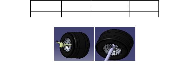
- Wheel Pattern:
Go-Kart must have 4 wheels and kart should be mounted using lock nuts.
Jack Points
Jack points must be oriented horizontally and perpendicular to the centerline of the go-kart. The jack point should be made of a flat steel plate attached to the bottom of the chassis.
Hitch Point
Every vehicle must have two hitch point one at the rear end and other at the front end. Hitch point will be used to attach push rod. Team members should fabricate detachable push rod that should have the capability of pulling the pushing the go-kart. It should be fabricated on the chassis body.
Push/pull Rod
Push/Pull rod is used to push or pull the vehicle from one place to another place by attaching pull rod to the hitch points which are fabricated on the chassis body.
Driver’s Seat
Driver seat must be of fire proof material and mostly bucket seat should be used in go-kart. The seat must be fixed at the bottom and at the sides. The driver seat must be fixed according to the comfortability of the driver during driving. For this process ergonomics of the driver should be studied and deigned in the software and analyzed the data.
Front Bodywork
The Front body work is designed to reduce the aerodynamic lift of the vehicle and should be designed to give driver a clear view of the obstacles present on the track.
Firewall
Firewall must be fire proof material and does not allowheat of the engine into the driver compartment. The firewall material must be of 1.5mm thickness. It separates all the fuel line system, Engine, motor and electrical connections from the driver. The firewall must be free from holes, drills, open patches etc.
Fast Guard
Fast guard or foot guard must be designed at the front bumper not to affect the driver legs during any collision or accidents. It should cover the top most leg part of the driver.
Floor Close-out
Floor close out should be made in the driver compartment to keep the legs during rest position. Floor closeout will be useful for driver during egress test, to jump out of the kart within 5 seconds. The floor closeout material should be of more thickness as it has to sustain the load of the driver during the egress test.
Driver Visibility
Driver visibility should be clear for the driver to observe the obstacles present on the track. The driver must have adequate visibility to the front and sides of the kart. The drivers view should not be restricted by the steering wheel.
Practical Work
Fabrication of Go-kart chassis
The fabrication of go-kart chassis starts after a series of researches of theoretical work on all the subsystems of the go-kart like Steering, Transmission and braking system and their position on the chassis body with calculations.
- The Required material for the fabrication of the go-kart should be ordered.
- Material should be cut into pieces and bended, according to the lengths of the chassis design.
- The material should be welded according to the lengths and angles based on the chassis design.
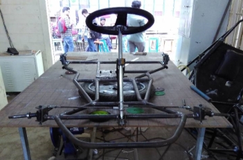
Chassis body during fabrication.
- Welding of Roll hoop to the chassis body supported by the braces.
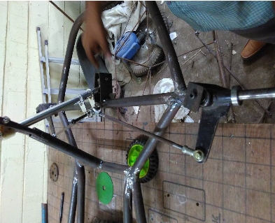
- Attachment of Steering Assembly (Steering column, Steering wheel, tie rods, c-clamps and spindles) to the go-kart chassis body at the front. Adjustment of C-Clamps angle according to the camber, caster angle and king-pin inclination should be perfectly welded.
- Arrangement of Transmission shaft and engine at the engine compartment. The sprocket, Disc brake should be fixed to the transmission shaft. The engine sprocket is fixed to the sprocket on the transmission shaft by means of a chain drive. The transmission shaft should be fixed to the chassis body means of bearings to provide easy movement of the shaft rotation. The bearings should be selected according to the outer diameter of the transmission shaft.
- Braking system used is Hydraulic braking system where the fluid is pressurized to hold the disc tightly (which is mounted on the transmission shaft) by means of a disc caliper. The brake pedal and the master cylinder will be present near to the front bumper and the disc caliper is attached to the disc at the rear side. The master cylinder and the disc caliper are connected by means of a brake hose pipe.
- Brackets are mounted on the chassis body for the attachment of floor close out and for the firewall sheets.
- Fixing of tires to the go-kart specified in the rulebook at front to the spindles and rear to the drive shaft. The front tires should be fixed to the spindles by placing the bearings and bushes into the front wheel for the easy movement of the front wheels.
- Electrical Wiring for the kill switches and brake light was done with proper insulation.
Innovation
This fire identification caution circuit depends on thermistor. A thermistor is only a variable resistor whose protection changes with temperature. Fire recognition is essentially conceivable by means of this minimal effort caution circuit.
A basic potential divider game plan utilizing thermistor is fit for detecting the temperature and alarming us with a signal. This is appropriate for your home security frameworks.
Parts required
1. Power supply Resistors (1kΩ)
2. Potentiometer (10KΩ)
3. Capacitor (10µF, 16V) BC548
4. Transistor High protection thermistor (NTC) Diode (1N4007)6V Buzzer
Working of flame caution circuit
Working depends on the switching property of transistor. The thermistor and R1 frames a potential divider arrange which drives the transistor. The heart of this circuit is a thermistor. Thermistors are minimal effort, effortlessly accessible temperature sensors generally utilized for uncomplicated temperature measurements. Thermistors are temperature touchy resistors. At the point when temperature expands protection offered by the thermistor abatement’s and the other way around. At ordinary temperature, the protection of the thermistor is around 10kΩ.All resistors change with temperature, however the semiconductor materials utilized for thermistors are particularly delicate to temperature. The transistor is turned ON by the voltage drop over the resistor R1. Consider the temperature of the climate is around 25°C, and after that the protection of thermistor is high so the voltage over the thermistor is additionally high as per the essential ohm’s law V=IR.
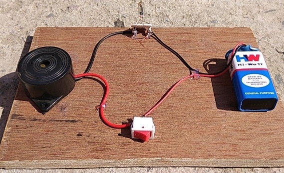
Fig.3: Fire Detector alarm
Testing of the Go-kart vehicle while running without attachment of Bumpers
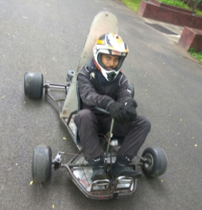
Fig.4.8
Testing
Weight test:
A weight of 2 persons of 180 kgs is placed on the vehicle under running at 30 km/hr. at this condition deformation of the vehicle is as per the analysis results.
Brake test:
Testing of brake has been done as per the rule book.
Vehicle speed -40 km/hr.
Braking distance -3 m.
Stopping distance -1.53m.
Stopping time – 0.95 sec.
Skid pad & autocross test:
This testing has been conducted as per rule book.
Distance between cones- 3 m.
Cornering radius – 5m.
Vehicle turning radius -1.26 m.
Acceleration test:
Acceleration of vehicle – 1.9129m/s2
Vehicle speed test:
Max velocity – 35km/hr @ 2400 rpm. 3300 rpm ekada
Electrical circuit testing: ( not necessary)
All kill switches and brake travel over switch are tested in running. Brake light is tested.
References
http://ijpam.eu/jsi/2017-116-5-7/articles/6/28.pdf
https://kartfab.com/go-kart-plans
https://www.scribd.com/doc/210560529/GO-KART-Design-Report-pdf
ISIE 3rd IKR 2017 RULEBOOK
Microsoft word- Faieza et al pdf.doc
If you're working on a university project and looking for dissertation writing help, the dissertation writing service at UKEssays.com can connect you with academic writers specialising in your field of study.
Cite This Work
To export a reference to this article please select a referencing stye below:
Related Services
View all


Related Content
All TagsContent relating to: "Mechanics"
Mechanics is the area that focuses on motion, and how different forces can produce motion. When an object has forced applied to it, the original position of the object will change.
Related Articles

DMCA / Removal Request
If you are the original writer of this dissertation and no longer wish to have your work published on the UKDiss.com website then please: