Factors that Influence the Mechanical Properties of Extruded Nylon Medical Device Tubing
Info: 7266 words (29 pages) Dissertation
Published: 15th Dec 2021
Tagged: MechanicsMedical Technology
To Investigate the Factors that Influence the Mechanical Properties of Extruded Nylon Medical Device Tubing
Abstract
The aim of this project was to investigate the factors that can change the mechanical properties of standard extruded medical device tubing and recommend any improvements to the current technique. Extensive research was undertaken to gain a deep understanding of all topics contained within this project from chemical formulations of polymers to the medical device industry as a whole. The procedure followed to produce medical grade tubes is outlined below along with the equipment needed to produce the tubing and carry out thorough testing. A sample of the research carried out in relation to this project is also shown below.
Glossary
(MRI) Magnetic Resonance Imaging
(EU) European Union
(CAD) Computer Aided Design
(FMEA) Failure Mode Effect Analysis
(OD) Outside Diameter
(ID) Inside Diameter
(PEEK) Polyether Ether Ketone
(MDD) Medical Device Directive
(AAT) Advanced Aging Time
(RT) Real Time
Nomenclature
| Symbol | Name | S.I Units |
| L | Length | mm |
| F | Force | N |
| M | Mass | kg |
| A | Area | mm2 |
| ID | Inside diameter | mm |
| OD | Outside Diameter | mm |
| Bp | Burst Pressure | Bar |
| σ | Stress | MPa |
Table of Contents
Click to expand Table of Contents
1. Introduction
1.1. Introduction
1.2. Aims and Objectives
2. Literature Review
2.1. Polymers
2.1.1. Overview of Polymers
2.1.2. Main Classes of Polymers
2.1.3. Nylons
2.1.4. Polymer Processing
2.1.5. Composites
2.2. Medical Devices
2.2.1. History of Medical Devices
2.2.2. Use of Plastics in Medical Devices
2.3. Test Equipment
2.3.1. Tensile Strength Tester
3. Materials & Methods
3.1. Introduction
3.2. Method for Changing Factors Through-out Trials
3.3. Tube Design and Material Used
3.4. Equipment Used
3.4.1. Tube Manufacturing Equipment
3.4.2. Tube Testing Equipment
4. Work Done to Date
4.1. Introduction
4.2. Tube Manufacture
5. Preliminary Results
5.1. Preliminary results
6. Future Work
6.1. Testing
6.2. Continual Research
7. Project Plan/ Gantt Chart
7.1. Project Plan
8. Discussion
8.1. Literature Review
8.2. Materials and Methods
8.3. Work Done to Date
9.Bibliography
Table of Figures
Figure 2‑1 Single screw extrusion machine (Abeykoon, 2011)
Figure 2‑2 A typical injection molding machine (Pruitt, 2011)
Figure 2‑3 Surgical scissors used in ancient Rome (University of Virginia, 2007)
Figure 2‑4 Typical Stress-Strain curve for a perfectly elastic material (Brown, 2002)
Figure 2‑5 Typical non-linear stress versus strain characteristic for a material with a yield stress greater than the failure stress (Brown, 2002)
Figure 3‑1 Low die gap parameter change.
Figure 3‑2 High die gap parameter reading.
Figure 3‑3 Low water bath temperature value.
Figure 3‑4 Low melt temperature value.
Figure 3‑5 High line speed value.
Figure 3‑6 Raw pure Nylon 12 polymer
Figure 3‑7 Raw Pebax 7233 polymer composite
Figure 4‑1 Novatec polymer bead dryer
Figure 4‑2 Temperature controlled water bath.
Figure 4‑3 Detailed breakdown of extruder machine setup.
Figure 4‑4 Digital readout from laser measuring device.
Figure 4‑5 Laser measuring device
Figure 4‑6 Belt puller for determining the speed of the extruded polymer from the die.
Figure 4‑7 Conveyor for collecting finished tubing.
Table of Tables
Table 2‑1 Classification of Polymers (Ghosh, 2001)
Table 2‑2 Comparison chart for commodity plastics and highly engineered plastics for the medical device industry and example of their uses (Sastri, 2013).
Table of Equations
Equation 2‑1 Stress formula (Brown, 2002)
Equation 2‑2 Percentage strain formula (Brown, 2002)
Equation 3‑1 Accelerated Aging Time (AAT) formula used to determine length of time in aging chamber (Westpak Inc., 2018)
1. Introduction
1.1. Introduction
Medical devices are an integral part of the modern word. The shear vastness of the medical device industry displays the wide array of products that can aid in diagnosing, treating and preventing illness. With the explosion of new technologies during recent years, it also demands that medical devices keep closely in toe. The market for medical devices in Europe (€63.6 billion) is nearly as large as that in the US (€79.4 billion) (Schreyögg, 2009). Both markets include items as diverse as medical aids (e.g. wound-care products), artificial body parts (e.g. hip endoprostheses), and technical equipment (e.g. MRIs) and are thus very heterogeneous. The specific device discussed within this report is nylon tubing which has many applications from fluid delivery to medical stent delivery in key-hole surgery. These devices have to fit within tight constraints such as outside diameter (OD), inside diameter (ID), concentricity, length, burst pressure and tensile strength which must be with pre-decided tolerances. Nylon is a typical polymer to manufacture medical grade tubes from due to its desirable mechanical properties such as drag, resistance to chemical corrosion, flexibility and tensile strength. One of the most common practices of manufacturing medical tubing is through extrusion. Some factors that are involved within this process can change the desired mechanical properties of the tubing which could lead to detrimental consequences such as death.
Through investigation of the manufacture of medical device tubing it was found that operators were being given a range between which the factors of water bath temperature, die gap, line speed and melt temperature could vary, the exact procedure for these changes will be discussed in section 3-2 of this report. This lead too many inconsistencies between batches of similar tubing which may lead to different batches having more or less desirable qualities such as tensile strength. It can also lead to a wastage of time to reach the required specification resulting in a loss of material and profits.
1.2. Aims and Objectives
The following are the aims and objectives of this thesis;
- To standardize tube extrusion practices
- To develop a mathematical model that can be applied to obtain the desired properties
- Mimic the manufacture of medical tubes
- Test manufactured tubing under controlled conditions
- Evaluate results and suggest improvements to the manufacturing process
- Produce CAD models of tubes
- Perform FMEA analysis of CAD model of tubes
- Reduce the occurrence of failed tubes due to the manufacturing process
2. Literature Review
2.1. Polymers
2.1.1. Overview of Polymers
The word plastic comes from the Greek verb plassein which means “to mold or shape”. Before the Second World War the class of plastics called the cellulosics were mainly produced from cellulose which is contained within plants. Until the mid-1950’s coal was the main raw ingredient for the production of plastics, as when coal is destructively distilled it breaks into four products: coal tar, coke, coal gas and ammonia. The resulting coal tar was the basis for many plastics such as polystyrene and nylons. In the modern era, the extensive development of the petrochemical industry has been the single biggest driver in the development of plastics, the two industries are intrinsically interconnected today and have an extreme degree of interdependence. The process of ‘cracking’ olefins to produce short chained fractions such as gasoline for fuel also produced ‘waste’ products which were later discovered to be the basis for most plastics today (Brydson, 1982). Plastics, due to their long chains of atoms or small molecules bonded in a repeating pattern have the ability to be shaped or moulded. Due to the refraction process of hydrocarbons such as oils the base for synthetic plastics and also natural plastics is the element carbon. Carbons electron configuration allows it to be easily bonded to other molecules to produce plastics, depending on which molecules and number of bonds this can produce many different plastics and also compounds of plastics that can be manipulated to produce more desirable characteristics such as increased rigidity or higher tensile strength. Polymers can be broken down into three structural groups, linear chained polymers, branched polymers or network polymers. Liner chained polymers can be distinguished into two subclasses:
- Homochain polymers which only contain carbon atoms in the main chain. These polymers are usually made using the ‘addition’ method of adding molecules too the main carbon atoms.
- Hetrochain polymers which can contain other atoms as part of the main chain. These polymers are usually made using ‘step-reaction polymerisation’.
Branched polymers are made by the condensation polymerisation of bifunctional monomers, this occurs when the addition of linear chained polymers creates secondary chains that are on the outside of the molecule and are not just connected to the main chain atom. Network polymers are formed by tri-functional, meaning three separate chains including the main base chain. This can create cross linking of higher molecular weight polymers, an example of a network polymer is the vulcanisation of rubber (Van Krevelen, 2009).
2.1.2. Main Classes of Polymers
Ghosh (2001) stated that polymers are classed into seven different categories which can be seen in the table below.
| Basis of Classification | Polymer Type |
| Origin | Natural, semisynthetic, synthetic |
| Thermal response | Thermoplastic, thermosetting plastic |
| Mode of formation | Addition, condensation |
| Line structure | Linear, branched, network |
| Application and physical properties | Rubbers, plastics, fibers |
| Tacticity | Isostatic, syndiotactic, atactic |
| Crystallinity | Non-crystalline, semi-crystalline, crystalline |
Table 2‑1 Classification of Polymers (Ghosh, 2001)
Below is an explanation of the four main basis of classification and the major polymer types contained within each class.
Origin
- Natural polymers are available within nature such as natural rubber and cellulose.
- Semisynthetic polymers are chemically modified natural polymers such as hydrogenated natural rubber.
- Synthetic polymers are man-made polymers and are normally conceived in a laboratory such as polyesters, polystyrene and poly-vinyl chloride.
Thermal Response
- Thermoplastic polymers can be softened and repeatedly reheated to a plasticised state without altering the properties, e.g. nylons, linear polyesters and polystyrene.
- Thermosetting polymers are originally created from a molten form but once they have cooled and set they cannot be reheated and reshaped this occurs in epoxy resins and diene rubbers.
Mode of Formation
- Addition polymers are formed from olefinic monomers, they all have a carbon atom along their main chain. They are produced by simply adding monomer molecules in quick succession along the main chain. Examples of such addition polymers include polypropylene and polyethylene.
- Condensation polymers are formed from reactions between bifunctional or polyfunctional molecules with reactive functional groups. The functional groups react with each other by condensing structural links such as occurs with polyethers and polyurethanes.
Line Structure
The line structure classification was discussed above e.g. linear, branched and network structures.
2.1.3. Nylons
Polyamide-imides are thermoplastic amorphous polymers that have exceptional mechanical, thermal and chemical resistant properties. These properties put polyamide-imides at the top of the price and performance pyramid. Polyamide-imides hold, as the name suggests, a positive synergy of properties from both polyamides and polyimides, such as high strength, melt processibility, exceptional high heat capability, and broad chemical resistance. Polyamide-imides hold, as the name suggests, a positive synergy of properties from both polyamides and polyimides, such as high strength, melt processibility, exceptional high heat capability, and broad chemical resistance.
2.1.4. Polymer Processing
There are many different ways of processing polymers from extrusion, injection moulding, thermoforming and calendaring. The first process to be discussed is polymer extrusion. Its key advantages are relatively low cost, straightforward design, ruggedness and reliability, and a favourable performance/cost ratio. This geometry is also referred to as a “single stage.” The single stage refers to the fact that the screw has only one compression section, even though the screw has three distinct geometrical sections!
The first section (closest to the feed opening) generally has deep flights. The material in this section will be mostly in the solid state. This section is referred to as the feed section of the screw. The last section (closest to the die) usually has shallow flights. The material in this section will be mostly in the molten state. This screw section is referred to as the metering section or pump section. The third screw section connects the feed section and the metering section. This section is called the transition section or compression section.
In most cases, the depth of the screw channel (or the height of the screw flight) reduces in a linear fashion, going from the feed section towards the metering section, thus causing a compression of the material in the screw channel. Later, it will be shown that this compression, in many cases, is essential to the proper functioning of the extruder. The basic operation of a single screw extruder is rather straightforward. Material enters from the feed hopper. Generally, the feed material flows by gravity from the feed hopper down into the extruder barrel. Some materials do not flow easily in dry form and special measures have to be taken to prevent hang-up (bridging) of the material in the feed hopper. As material falls down into the extruder barrel, it is situated in the annular space between the extruder screw and barrel, and is further bounded by the passive and active flanks of the screw flight: the screw channel. The barrel is stationary and the screw is rotating.
As a result, frictional forces will act on the material, both on the barrel as well as on the screw surface. These frictional forces are responsible for the forward transport of the material, at least as long as the material is in the solid state (below its melting point). As the material moves forward, it will heat up as a result of frictional heat generation and because of heat conducted from the barrel heaters. When the temperature of the material exceeds the melting point, a melt film will form at the barrel surface. This is where the solids conveying zone ends and the plasticating zone starts.
It should be noted that this point generally does not coincide with the start of the compression section. The boundaries of the functional zones will depend on polymer properties, machine geometry, and operating conditions. Thus, they can change as operating conditions change. However, the geometrical sections of the screw are determined by the design and will not change with operating conditions. As the material moves forward, the amount of solid material at each location will reduce as a result of melting. When all solid polymer has disappeared, the end of the plasticating zone has been reached and the melt conveying zone starts. In the melt-conveying zone, the polymer melt is simply pumped to the die. As the polymer flows through the die, it adopts the shape of the flow channel of the die. Thus, as the polymer leaves the die, its shape will more or less correspond to the cross-sectional shape of the final portion of the die flow channel.
Since the die exerts a resistance to flow, a pressure is required to force the material through the die. This is generally referred to as the die head pressure. The die head pressure is determined by the shape of the die (particularly the flow channel), the temperature of the polymer melt, the flow rate through the die, and the rheological properties of the polymer melt. It is important to understand that the die head pressure is caused by the die, and not by the extruder! The extruder simply has to generate sufficient pressure to force the material through the die. If the polymer, the throughput, the die, and the temperatures in the die are the same, then it does not make any difference whether the extruder is a gear pump, a single screw extruder, a twin screw extruder, etc.; the die head pressure will be the same. Thus, the die head pressure is caused by the die and by the flow process, taking place in the die flow channel. This is an important point to remember (Rauwendaal,2013).
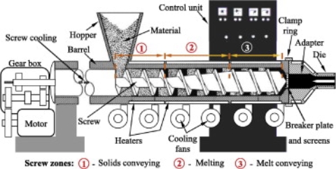
Figure 2‑1 Single screw extrusion machine (Abeykoon, 2011)
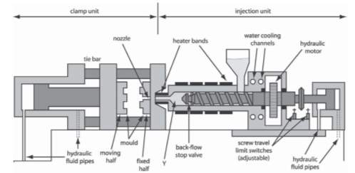
Figure 2‑2 A typical injection molding machine (Pruitt, 2011)
2.1.5. Composites
Composites can be defined as materials that consist of two or more chemically and physically different phases separated by a distinct interface. The different systems are combined judiciously to achieve a system with more useful structural or functional properties non attainable by any of the constituent alone. Composites, are becoming an essential part of today’s materials due to the advantages such as low weight, corrosion resistance, high fatigue strength, and faster assembly. They are extensively used as materials in making aircraft structures, electronic packaging to medical equipment, and space vehicle to home building. The basic difference between blends and composites is that the two main constituents in the composites remain recognizable while these may not be recognizable in blends.
The predominant useful materials used in our day-to-day life are wood, concrete, ceramics, and so on. Surprisingly, the most important polymeric composites are found in nature and these are known as natural composites. The connective tissues in mammals belong to the most advanced polymer composites known to mankind where the fibrous protein, collagen is the reinforcement. It functions both as soft and hard connective tissue. Composites are combinations of materials differing in composition, where the individual constituents retain their separate identities. These separate constituents act together to give the necessary mechanical strength or stiffness to the composite part. Composite material is a material composed of two or more distinct phases (matrix phase and dispersed phase) and having bulk properties significantly different from those of any of the constituents.
Matrix phase is the primary phase having a continuous character. Matrix is usually more ductile and less hard phase. It holds the dispersed phase and shares a load with it.
Dispersed (reinforcing) phase is embedded in the matrix in a discontinuous form. This secondary phase is called the dispersed phase. Dispersed phase is usually stronger than the matrix, therefore, it is sometimes called reinforcing phase.
Most commercially produced composites use a polymer matrix material often called a resin solution. There are many different polymers available depending upon the starting raw ingredients. There are several broad categories, each with numerous variations. The most common are known as polyester, vinyl ester, epoxy, phenolic, polyimide, polyamide, polypropylene, polyether ether ketone (PEEK), and others. The reinforcement materials are often fibers but can also be common ground minerals. The various methods described below have been developed to reduce the resin content of the final product.
As a rule of thumb, hand layup results in a product containing 60% resin and 40% fiber, whereas vacuum infusion gives a final product with 40% resin and 60% fiber content. The strength of the product is greatly dependent on this ratio. Polymer matrix composites are very popular due to their low cost and simple fabrication methods. Use of non-reinforced polymers as structure materials is limited by low level of their mechanical properties, namely strength, modulus, and impact resistance (Thomas, et al. 2012)
2.2. Medical Devices
2.2.1. History of Medical Devices
Sastri (2013) stated that medical devices range from simple devices like syringes, and bandages to highly sophisticated imaging machines and long-term surgical implants. Examples of medical devices include surgical instruments, catheters, coronary stents, pacemakers, magnetic resonance imaging (MRI) machines, X-ray machines, prosthetic limbs, artificial hips and knees, surgical gloves, and bandages. The Medical Device Directive (MDD) classifies devices as Class I, Class II, Class IIa, and Class III in order of increasing risk.
An example of a Class I medical device is simple bandage, a Class IIa is polymer film dressing, an example of a Class IIb device include diagnostic x-ray devices and Class III devices which carry the highest level of risk include devices such as prosthetic heart valves.
Materials like metal, wood, ceramics, glass, and plastics are used in many medical device applications. Surgical instruments have been manufactured since the dawn of human existence. Rough instruments for performing round craniotomies were discovered in archaeological digs around the world. The Bronze and Iron Ages saw the development and use of surgical instruments such as scalpels, lancets, curettes, tweezers, forceps, probes, dilators, tubes, and surgical knives. Over time, many other instruments were invented and designed for amputations and other surgical procedures. With the discovery of the use of ether, chloroform, and nitrous oxide as anesthetic agents, new surgical instruments were invented to penetrate various inner parts of the body.
Sterility also became a major need. The nineteenth and twentieth centuries saw an explosion of medical devices, and materials such as stainless steel, titanium, ceramics, and plastics were used in their manufacture. The demand for precision instruments for microsurgery in neurosurgery, ophthalmology, and otology was possible, and in the second half of the twentieth century, energy-based instruments like electrocauteries, ultrasound, electric scalpels, surgical tools, and surgical robots were developed.
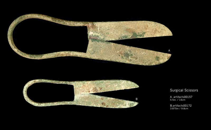
Figure 2‑3 Surgical scissors used in ancient Rome (University of Virginia, 2007)
2.2.2. Use of Plastics in Medical Devices
The increased use of disposable devices is leading to the increased use of plastics over metals, ceramics, and glass. With the increase in infectious diseases around the world, disposables are the product of choice, in order to prevent the spread of infection. Shorter hospital stays and an increase in home health care also have increased the use of disposables. The changes in sterilization technologies from steam sterilization to radiation and high-energy sterilization also have increased the use of plastics, as they are more amenable to gamma and electron beam radiation sterilization. Compared to metals, glass, and ceramics, plastics require much lower processing temperatures (25 – 500 °F) versus steel (2500 – 4000 °F), glass (2700 – 4200 °F), and ceramics (3600 – 5400 °F).
As devices become functionally more complex and smaller, their components (like gears, levers, buttons, axels, actuators, and counters) need to be smaller, while still maintaining their high performance, dimensional stability, durability, and reliability. Micromolding of such components with plastics allows the manufacture of precision parts with tight tolerances. A typical plastic is about half as heavy as aluminium and one-sixth as heavy as steel. As a result, products that use plastics have a significant positive effect on transportation costs, cost of parts per unit weight, and performance-to-weight ratio.
Depending upon the end use, the environment of use, and the chemicals that the device might be exposed to plastics provide a wide range of selections for the application. Many new drug therapies require the use of lipids for dissolution and delivery. Some plastics are inherently lipid resistant and others can be made lipid resistant with the incorporation of additives. With more applications for minimally invasive devices and implants, biocompatibility is another requirement for such applications. Many plastics are inherently biocompatible or can be made biocompatible. This is a major advantage of plastics over metals (Sastri, 2013). Below is a comparison chart between commodity plastics found in everyday life and highly engineered thermoplastics used in the medical device industry:
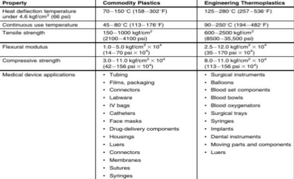
Table 2‑2 Comparison chart for commodity plastics and highly engineered plastics for the medical device industry and example of their uses (Sastri, 2013).
2.3. Test Equipment
2.3.1. Tensile Strength Tester
Brown (2002) determined that short-term tensile characteristics of a material are probably the most commonly derived of all the properties that can be determined. Although there are many standards relating to short-term tensile testing (the most significant of these will be discussed later), they all endeavour to quantify a number of specific characteristics which relate to the strength and deformation of a material. Knowledge of these characteristics can give materials scientists, technologists, materials specifiers and designers an insight into the potential performance of a material. Tensile stress-strain characteristics are derived by monitoring both the force required to pull a material apart and the displacement that the material undergoes as a result of the applied force at a constant deformation rate. In order to convert the force and displacement into stress-strain characteristics it is necessary to introduce a number of definitions:
Stress (MPa) = Force (N) / Area (mm 2)
Equation 2‑1 Stress formula (Brown, 2002)
It is common practice to express strain as a percentage and this is simply accomplished by multiplying by 100:
Strain (%) = (Extension δ l (mm) / Original length l 0 (mm)) x 100
Equation 2‑2 Percentage strain formula (Brown, 2002)
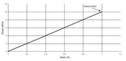
Figure 2‑4 Typical Stress-Strain curve for a perfectly elastic material (Brown, 2002)
An idealised stress-strain relationship for a typical tough plastic material with a yield stress greater than the failure stress is shown in Figure 6.
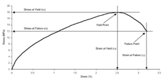
Figure 2‑5 Typical non-linear stress versus strain characteristic for a material with a yield stress greater than the failure stress (Brown, 2002)
The core piece of apparatus is the tensile testing machine (which generally can also be used for compression, flexural and shear tests) which incorporates fixed and driven members together with a load cell for measuring force. Grips are required to hold the test piece and when elongation or modulus is to be measured an extensometer is necessary (Brown, 2002).
3. Chapter Three Materials & Methods
3.1. Introduction
This section will explain the methodology and what materials and equipment were used during this project. It will show each step in the manufacture of the nylon tubes and the equipment required. It will also discuss the testing procedure to determine the changes in mechanical properties.
3.2. Method for Changing Factors Through-out Trials
The procedure for changing process parameters was as follows;
Low die gap – this was the distance between the face of the die and the position when the semi solid tube enters the water bath. The typical measurement for this parameter is 11mm, to obtain a low die gap the water bath was moved to 6mm from the die face as shown in Figure 3-1.
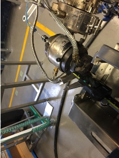
Figure 3‑1 Low die gap parameter change.
High die gap – The same procedure was followed for high die gap as low die gap except the water bath was moved to 22mm from the die face as seen in Figure 3-2.
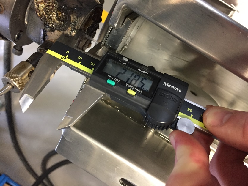
Figure 3‑2 High die gap parameter reading.
Low water bath temperature – The temperature of the water contained in the water bath was reduced be increasing the flow of cold water into the bath and reducing the flow of heated water. The standard value that was selected for water temperature was 25°C, this value was lowered to 18°C as seen in Figure 3-3.
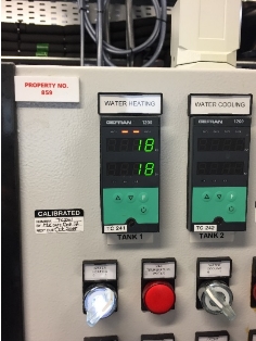
Figure 3‑3 Low water bath temperature value.
High water bath temperature – To obtain a high water bath temperature the reverse of the procedure for low water bath temperature was followed. The value for high water bath temperature was set at 40°C.
Low melt temperature – This parameter was altered by reducing the value of the heating pads on the outside of the extruder barrel. The standard value for this parameter was 490°F. This was lowered to 470°F. This is shown in Figure 3-4.
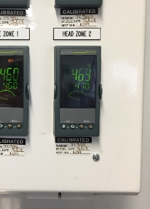
Figure 3‑4 Low melt temperature value.
High melt temperature – This factor was altered by increasing the temperature of the heat pads on the outside of the barrel. This value was set to 510°F.
High line speed – This parameter determines the speed at which the tube is pulled through the process of cooling. This was changed by setting the value of the puller belt to 32m/min. The standard value for the parameter is 19m/min. this is shown in Figure
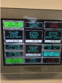
Figure 3‑5 High line speed value.
Low line speed – This parameter is obtained by lowering the line speed to 11m/min.
3.3. Tube Design and Material Used
The specifications of the manufactured tube were as follows:
- Outside diameter – 1mm ± 0.05mm
- Inside Diameter – 0.95mm ±0.05mm
- Length – 300mm ± 30mm
- Single layered
- Single lumen
- 300 pieces per changed factor
- 8 trials per material
The polymers that was selected for the tubes were Nylon 12 which is a pure nylon that has no additives added to its chemical structure and Pebax 7233 which is a composite polymer that has a base material of nylon. The use of two different materials would lead to a comparison being drawn whether the factors changed during production had a greater effect on a pure or composite nylon.
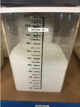
Figure 3‑6 Raw pure Nylon 12 polymer
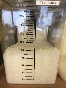
Figure 3‑7 Raw Pebax 7233 polymer composite
3.4. Equipment Used
3.4.1. Tube Manufacturing Equipment
The equipment used to manufacture the two different types of nylon tubes was a single barrel extrusion machine as shown in Figure 1. This machine was used as it directly mimicked the real-world production process of these tubes. A 1mm holed diameter die coupled with a 0.95mm air flow tip was used to acquire the exact dimensions of the tube. A high speed rotary cutter was used to cut the tubes to exact length. A variable temperature open top water bath was used for solidifying the extruded molten polymer.
3.4.2. Tube Testing Equipment
The testing apparatus for determining the two tube properties which are being investigated as part of this project are:
- Tensile tester, which has been discussed above in section 2.3.1 of this report.
- Burst pressure tester which submerges the tube underwater with both ends sealed to prevent water from entering the cavity of the tube. The pump the subjects the tube to pressurised air which increases incrementally over time until the tube bursts. This is an accurate indicator of the strength of the tube when subjected to internal pressures.
- Aging chamber, is used to simulate natural aging of the tube. This is done by placing the tube in a specially designed oven which maintains a desired temperature for a period of time which is calculated using the formula:

Equation 3‑1 Accelerated Aging Time (AAT) formula used to determine length of time in aging chamber (Westpak Inc., 2018)
4. Work Done to Date
4.1. Introduction
Throughout this project to date a lot of research has been completed to acquire any relevant information about the wide array of topics this project involves from a detailed understanding of polymers and the chemistry related to the polymers medical device industry, a complete history of medical devices from the Ancient Roman era to the present day. A small example of the main research topics that were researched for this project are shown above in chapter two of this report. The significant task of tube production has also been completed which will be outlined below. A Microsoft excel sheet has also been prepared to record results obtained from testing, this is shown in appendix
4.2. Tube Manufacture
To manufacture the medical tubing for this project the polymer beads as seen in Figure 3-1 and Figure 3-2 were firstly dried to lower the moisture content using a Novatec polymer dryer show in Figure 4-1 this ensured that during the melting process within the barrel of the extruder steam did not build up creating unsafe conditions.
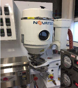
Figure 4‑1 Novatec polymer bead dryer
The dried beads were then loaded into the barrel of the extruder under the force of gravity. They are then picked up by the screw within the extruder barrel and moved along heating zones as shown in Figure 2-1. Once in a molten state they are forced through a die which has a tip that passes compressed air through the extruded polymer to create the lumen. A break-down of this step is shown below in Figure 4-3. Once the extruded tube exits the die it is semi-cooled from contact with cool air, this created the die gap factor of the investigation, the semi cool tube is then fed into a temperature controlled water bath (Figure 4-2) which cools the tube fully solidifying its shape, the temperature of this bath was also a factor that was thought to have an influence on the mechanical properties of the tube.
Figure 4‑2 Temperature controlled water bath.
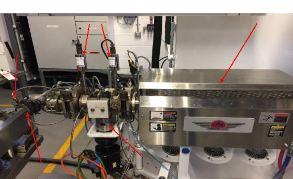
Figure 4‑3 Detailed breakdown of extruder machine setup.
The solidified tube was then passes through an air drier to remove any excess liquid of the surface of the tube. To accurately measure the critical dimensions of the tube it was passed through a laser measuring device (Figure 4-5) which produced a digital readout for the operator to monitor as seen below in Figure 4-4. The tube was then pulled by two adjacent belts, this determined the line speed factor of the investigation as seen in Figure 4-6.
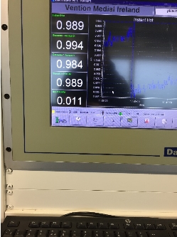
Figure 4‑4 Digital readout from laser measuring device.
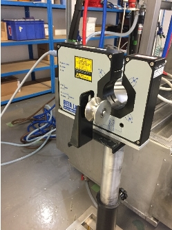
Figure 4‑5 Laser measuring device
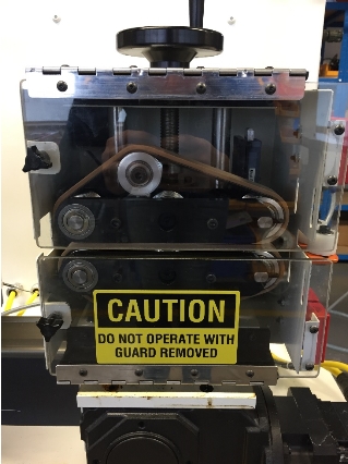
Figure 4‑6 Belt puller for determining the speed of the extruded polymer from the die.
The continuous tube was then fed through a rotary cutter which cut the tube to the length specified, these cut tubes were fed onto a conveyor (Figure 4-7) and finally collected from the operator.
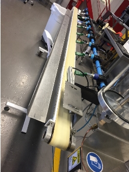
Figure 4‑7 Conveyor for collecting finished tubing.
5. Preliminary Results
There are no preliminary results at this time as no testing has been carried out.
6. Future Work
6.1. Testing
All mechanical property tests are to be carried out by the week beginning 22nd of January 2018, as testing equipment mentioned above in section 3.4.2 will be available from this date. This can be seen on the project Gantt chart below in section . The tubes will also be subjected to an aging chamber which is discussed in section 3.4.2 for a total of 19 days which is the equivalent to six months aging.
6.2. Continual Research
The literature review for this project is ongoing and will not be completed until final write up begins to ensure a deep knowledge of the topics contained within this project.
7. Project Plan/Gantt Chart
7.1. Project Plan
Due to the extensive nature of this project there will be six weeks allocated for final write up which allows seven more weeks from the present date to analysis results and continue researching topics related to this project.
8. Discussion
In this chapter I will discuss the development of the project thus far and outline any problems that were encountered in-preparation for this report.
8.1. Literature Review
The literature review I have found to be the most challenging aspect to this project as it requires a vast amount of time sieving through extensive amounts of information which can be very tedious. Although with a large amount of research already completed I feel I have a good understanding of all aspects contained within this project.
8.2. Materials and Methods
The decision to compare two similar materials I feel will add another level to the results and analysis and produce a clearer picture of exactly which factors have an effect on the mechanical properties of the respective tubes.
8.3. Work Done to Date
I am pleased with the progress of the project as the actual manufacture of the tubes was a large milestone in the project and to have this work completed before February is encouraging in itself.
9. Bibliography
Schreyögg, J., (2009), ‘Balancing adoption and affordability of medical devices in Europe’, Health Policy, 92(3), 218-224
Brydson, J.A., (1982). Plastics Materials. (fourth ed.), Butterworth Scientific.
Van Krevelen, D. W., (2009). Properties of Polymers: Their Correlation with Chemical Structure; Their Numerical Estimation and Prediction from Additive Group Contributions. (fourth ed.), Elsevier.
Ghosh, P., (2001), Polymer Science and Technology: Plastics, Rubbers, Blends and Composites, (second ed.), Tata McGraw-Hill.
Rauwendaal, C., (2013). Polymer Extrusion. (fifth ed.), Carl Hanser Verlag: Munich.
Sabu, T., et al., (2012) Polymer Composites : Macro- and Microcomposites, John Wiley & Sons
Sastri, R., (2013), Plastics in Medical Devices : Properties, Requirements, and Applications, Elsevier Science
Abeykoon C. Modelling and control of melt temperature in polymer extrusion.Ph.D. thesis. Queen’s University Belfast; 2011.
Surgical Instruments from Ancient Rome, University of Virginia. 2007
Pruitt, L., (2011). Mechanics of Biomaterials: Fundamental Principles for Implant Design, Cambridge University Press: UK
Visaka, P. M., Sabu, T., (2012). Handbook of Engineering and Specialty Thermoplastics, Nylons: Nylons, John Wiley & Son
Cite This Work
To export a reference to this article please select a referencing stye below:
Related Services
View all


Related Content
All TagsContent relating to: "Medical Technology"
Medical Technology is used to enhance the medical care and treatment that patients are given in healthcare settings. Medical Technology can be used to identify, diagnose and treat medical conditions and illnesses.
Related Articles
DMCA / Removal Request
If you are the original writer of this dissertation and no longer wish to have your work published on the UKDiss.com website then please: