Material and Manufacturing Analysis of Engineering Components for the Titanic
Info: 9963 words (40 pages) Dissertation
Published: 2nd Sep 2021
Tagged: EngineeringMaritime
Contents
2. Materials used for construction:
5. Standard forms and quality of the material
8.1 Joining plates to the hull
8.2 Rivets which contributed to the disaster
8.3 Steel frame of the hull construction
8.4 The failure of the Hull of ship
9. Modes of failure of titanic
10. Safety factors of materials
11.3 Normalising (before rolling plate)
11.4 Tempering (after rolling plate)
12.2 Magnetic particle testing
14.1 Impact test result analysis
16 Non-destructive testing result analysis
Executive Summary
The overall purpose of this report is to highlight the key failures which led the titanic to sink. This includes concepts such as material & manufacturing failures in components which ultimately played a big part in the disaster which unfolded during the year of 1912. The method I used to carry out the analysis included doing destructive and non-destructive testing on different material specimens to see weather the materials we have today could of had impact back then as well as analysing previous manufacturing methods to see if they were at fault for the disaster in any way. The results that were collected show us that materials and manufacturing process were partially at fault for the disaster and that alternatives materials and manufacturing methods should have been sourced in order to limit the damage to vessel at that time. The report has series of conclusions which state the alternative materials and methods they could have used back then. The recommendations of this report is that changes should be implemented in the way we source and choose materials for certain applications without disregarding the unfoseen consequences of our actions, the ship building industry should be aware of these mistakes that have previously occurred and should never happen again.
1. Introduction
The titanic was one of the supreme distinguished, British passenger liners; it was commissioned by the white star and was manufactured in Harland and Wolff shipyard, which is situated in Belfast. The manufactures of historic ship started work on the date 31st March 1909. The titanic was an iconic structure, it was the most quickest and most impressive liner created during that era.
After three years passing, the titanic construction had been completed, the “deluxe streamline machine” was ready to set sail from Southampton to New York, on-board was many civilians which included stingy millionaires to heartbroken emigrants, all in searching for a new life in the USA.
Whilist the voyage was taking its toll on the fifth day, the titanic was making an instantaneous progress across the Atlantic Ocean. The commander of the vessel had set a new course as he had previously heard previous ships, commentary that ice will be in the titanic path. During the night of Sunday 14th February 1912, temperatures, severely destabilised, the sky was clear and the sea was calm like a floating river, all these influential conditions made ice in the sea, difficult to sea in the ocean.
At 11:40pm on the same day, a lookout spotted a gigantic ice berg in the path of barge and he sounded the alarm, the alarm came too late, as 40 seconds later the iceberg slashing a series of holes on the side of the hull, the titanic had six section which were meant to be water tight but they were breached, five of the water tight areas were being invaded within an hour, as the result of this the titanic had started to sink, within 3-5 hours later the ship was completely submerged in to the sea, Which resulted in loss of lives and seen of chaos amongst the families of the dead.
2. Materials used for construction
The titanic was constructed out of:
- Thousands of one-inch thickness mild-steel plates.
- Around three million steel and wrought iron rivets
- The plates of streamline machine were made out of low grade steel.
The hull of the titanic was riveted three times, they used mild steel rivets which were metal and double rivets of wrought iron and these were used on the central length of the barge, where they presumed maximum tension anticipated to be.
| Table II. The Composition of Steels from the Titanic, a Lock Gate, and ASTM A36 Steel | |||||||||
| C | Mn | P | S | Si | Cu | O | N | MnS: Ratio | |
| Titanic Hull Plate | 0.21 | 0.47 | 0.045 | 0.069 | 0.017 | 0.024 | 0.013 | 0.0035 | 6.8:1 |
| Lock Gate* | 0.25 | 0.52 | 0.01 | 0.03 | 0.02 | — | 0.018 | 0.0035 | 17.3:1 |
| ASTM A36 | 0.20 | 0.55 | 0.012 | 0.037 | 0.007 | 0.01 | 0.079 | 0.0032 | 14.9:1 |
| *Steel from a lock gate at the Chittenden ship lock between Lake Washington and Puget Sound, Seattle, Washington. | |||||||||
The use of using wrought iron rivets and mild steel rivets was ultimately one of the reasons for the titanic disaster, instead they could have used steel rivets, which is a ferrous metal and has really good tensile strength, whereas the iron rivets aren’t as strong.
Table 1 Composition of steel (Titanic) (Felkins, 1998)
2.1 Chemical composition
From recent a studie, it’s been claimed that the hull of the titanic contained low nitrogen content, this means that the steel wasn’t made by the proper processes which is normally used to make the steel; this is called the Bessemer process. However, they used the hearth furnace which was used to make steel, which involves the steel being placed on a shallow hearth and burning of gases and hot air over it.
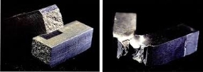
Figure 1 Steel samples that have been tested from Titanic (Gannon, 1995)
Metals are extremely versatile type of material and have a huge range. The properties and performance of the metal is from its direct structure, Metals are a kind of material that is used for several different purposes depending on the form of metal that is used, metals are typically appeared to have a glossy surface, strong in strength and have a good electrical and heat conductivity, metals are commonly malleable and easy to bend this is important in production
Ferrous metals that contain iron in them; examples of ferrous metals are cast iron, stainless steel and carbon steel. These metals usually have a high density, malleable to shape, and do not rust.
2.3 Metallic bonding
Steel and iron have these key properties of metals which distinguishes them from other materials such as there bonding, in most metals. Metallic bonding provides free electrons, resulting in high thermal and electrical conductivity, it also provides glue in bonding metal atoms together, the bonding within the structure allows the metal structure to move, which then gives the metal there inherent of plasticity.
In the diagram below it shows that the metal ions have free electrons on the outer shells of the metal atoms.
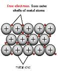
Figure 2 Free electron Structure
A common characteristic of metallic elements is that they contain only one to three electrons in the outer shell, when an element has only had one, two and three valence electrons, the bond between these electrons and nucleus relatively weak. The robust metallic bonding usually means it will be dense, strong materials with high boiling and melting points.
3 Crystal structures
All metals, have a crystal structure, the atoms within the metal arranges its self into a geometric lattice.
Body- centred cubic
The figure of atoms in a body centred cubic is that 1/8th of an atom belongs to the corners of a body centred cubic and there is one in the centre so this means it totals up to 2 atoms. The body centred cubic structure of iron was used on the rivets of the titanic and the mild steel used on the hull of the ship can come in a body centred cubic lattice structure.
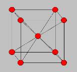
Figure 3 Body-centred cubic structure
The atoms within these metals are closely packed together and are quite dense and are fairly ductile.
2.1 Allotropes
Most metals retain their crystal structure but a few important one change their structure depending on the temperature.
Iron has BBC structure when it’s heated above a certain temperature (912C) it transforms into a FCC structure; these different forms are called allotropes.
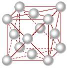
Figure 4 Face-centred cubic structure
2.2 Microstructure of steel
Steel is fundamentally an alloy of iron and carbon, in this universe there are many different types, ranging from soft ductile sheet steels to hard steel. The properties of the steel depend on their microstructure.
A Phase of iron is known as ferrite. Iron is able to exist in different phases or atomic arrangements based upon its temperature. At room temperature, iron exists as a body centre cubic structure called ferrite.

Figure 5 Ferrite crystal structure
Ferrite is mostly pure iron with small particles of carbon; this makes the material soft and easy to shape. The carbon dissolves in the iron interstitially, that is smaller carbon atoms fit between the iron atoms. The maximum carbon content in a ferrite is 0.02%
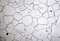
Figure 6 Microstructure of ferrite
3.4 Structure of carbon steel
Every crystal has to cool down from a liquid to a solid, carbon steels has a process which produces the crystals is a bit complicated. Iron combined with carbon will form iron carbide, many people know this is known as cementite, which has a distinctive colour white and is very firm as well as brittle.
If steel has more cementite, the more brittle and breakable it comes, when cementite forms in steel, 87% is iron and 13% is cementite. This structure is called pearlite. Low carbon steel contains crystals which have iron and pearlite.
3.5 Solidification
As the liquid in a metal cools, small particles form and acts like a seed around the crystal structure, many of these seeds form independently and a crystal which grows around each one. As they grow they interfere with neighbouring crystals and many randomly arranged crystalsform in to metal.
When the steel was made for the titanic, we can argue that steel didn’t solidified properly which then caused a malfunction in the crystal structure meaning the properties of that material were reduced, which means that the material was constructed accurately when manufactured.
3 Grains
Whenever a crystal grows it is known as grain.
The grain structure has a large influence on the properties of the metal.
A structure with small grains will improve the strength, hardness and impact resistance of metals.
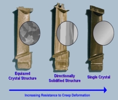
Figure 7 Grain structure
As we all know materials have small grains concealed within their structure, I can infer from what I know that that the metals were manufactured to a poor quality which resulted in the grains in the material being bigger than normal, as from previous research metals with small grains will normally have a good strength, hardness and good resilience to impact, I can therefore assume the steel on the titanic didn’t have these properties, which may have contributed to this terrible event to take place.
4 Periodicity
The titanic was made out of steel; steel is not in the periodic table because it’s not an element and the periodic table contains elements only. Steel contains a mainly iron, which is a transition element.
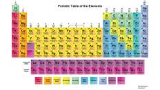
Table 2 Periodic table
These are the many properties of iron, which are stated below:
- Iron is the first element in the eighth column of the periodic table. It is classified as a transition metal.
- Iron which is known as pure is fairly soft, it is very reactive and will readily corrode or rust. It is malleable and a good conductor of electricity and heat.
- From all the elements in the periodic table iron is the greatest naturally magnetic of the elements.
- Iron becomes significantly tougher when alloyed with other elements such as carbon.
- Iron can be found in four allotropic forms. The most stable form of iron at normal temperatures is alpha iron and is known as ferrite.
These are typical properties of a transitional element:
- Transition elements will form colored compounds
- Every transition element, we know on this earth, has a good conductivity of heat and electricity.
- All transition elements can be beaten in to shape using a mallet and can be deformed into shape easily.
- Transition elements are usually hard as well as tough
- Higher densities are usually acquired by transition elements.
5 Standard forms and quality of the material
When the titanic was constructed the hull of the ship was formed by 2000 steel plates, which were held by 3 million rivets. The rivets of the titanic were made out made out of no 3 round bar, the rivets were manually made by casting into bar. The rivets and plates were used to hold the hull of the titanic together by reinforcing it by using a t-section. Please refer to figure 8
plates


Rivets
T-section
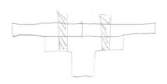
Figure 8 T-sections used to reinforce plate
The steel plates used on the titanic was inadequate as it was low- grade as well as being brittle which was incorporated in its properties as solid state. The steel was manufactured by using open hearth furnace, the hearth process was used for the bulk of the cheaper grades of steel. This process affected the quality of the plates used on the titanic and the toughness and other properties of the steel which was like they were unknown, when this tragic disaster took place.
T-sections are being made from a process called extrusion and the plates of the titanic are made from a manufacturing process called hot rolling.
Extrusion is a metal creating process which involves a work piece, of a certain distance and cross-section, “by forcing it to go through the die of a smaller cross-sectional area, this creates a new section”. The distance of the piece which is extruded can fluctuate; this depends on the amount of material used and the profile extruded. (Manufacturing, no date)
T- sections are good structural elements as they are able to bear heavy and large loads from the resistance which is created by the beam or internal reinforcements. T- sections can be used on ships, piers and finally bridges, the list is endless. This sort of section has more than one pillar, with a horizontal bed on top. However, the upright bit of the pillar is carrying the maximum compression applied, when this happens the material alters over several years but the simple structure stays the same. The only negative about T-sections is that they exposed to shear stress, this means extra material would have to be added to reduce the stress levels, depending on application.
A process called hot rolling was used to make the titanic plates, this process involves heating up steel approximately 1700 Fahrenheit which is far above “recrystallation temperatures, when this process is done to steel it can now be formed and shaped easily” and the sizes can be increase as it becomes bigger. Hot rolled steel is stereotypically less expensive than cold rolled steel because it mainly manufactured without any treatments in the methods used to create it, so therefore making the steel hot again Is not needed. When the cooling process takes place steel expands due to austenite to ferrite phase transition, FCC to BCC structure. This is how rivets fill up their holes. (Supermarkets, 2014)
Plate was used on the titanic, to form the hull, the reason why plate was used was due to its material properties it provided, and it was believed that using a process called hot rolling would increase the strength of the steel, making it better than other materials available on the market. Another reason why the hot rolling was ideal to make the plates, it allowed the steel to be stretched out more, meaning they could create the any thickness of plate, which was required to cover the mass-surface area of the hull.
6 Open-hearth furnace
One of the critical purposes of using an open hearth- furnace is that it removes excess carbon and other impurities from iron to create steel. Manufacturing steel is extremely challenging, due to the high melting points used in manufacturing but using this process has overcome these tricky obstacles.
The open hearth- process was used to manufacture the steel rivets for the titanic. The process was favourable amongst material manufactures because it allowed the “high melting points and decontaminating of large amounts of unused iron and steel.” These were one of the many positives of using this process; another reason why they used this process was because it did not expose the steel to large quantities of nitrogen, when steel is exposed to nitrogen it becomes more brittle, meaning it’s easy to control and manufacture. (Britanica, 2008)
7 Rivets used on titanic
In the rivets used on the boat, there was high slag content and it was aligned in the direction of the grain structure, which therefore means the iron that was used was rolled. Slag content in the rivets was more than three times as high as is normally found in modern wrought iron, making it less ductile and more brittle. Furthermore, when the titanic hit the iceberg, typically rivets should distort before failing but in this case the ductility and water temperatures below sub-zero, the rivets had become extremely brittle.
8.1 Joining plates to the hull
“The steel rivets weren’t as often due to their expense. The steel rivets attached to plates and hull + frame and had to be created by hydraulic riveters; these were” extremely large U-shaped steel machines upwards of six feet high that had to be laboriously positioned on either side of the plate to be riveted”. Then the rivet, were shaped similar to a blunt round headed nail, would be heated and inserted into its hole through the two overlapping hull plates to be joined, and squeezed between the jaws of the riveter. “This squeezing formed heads on both ends, and as the rivet cooled, the resulting explanation due to phase transformation provided tension that held the two steel hull plates together in a watertight joint”. Please refer to figure 9
8.2 Rivets which contributed to the disaster
In the first picture shown, the rivets were used to seal the plate’s hull together, which therefore hammered the end on exterior.
In the second picture, the pressure which was from the iceberg may have caused some of the rivets to come open, which therefore caused the seams to open, when this collision happened.
In the third picture, the steel could and rivets couldn’t take the any more pressure from the iceberg. This caused the water to torrent in.
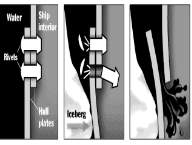
Figure 9 Diagram of how the rivets were fastened
8.3 Steel frame of the hull construction
During that period of time it was a well-known practise, that warship production and most trader ship construction to construct an inner skin, which had the exact distance away from the outer skin, which was along the bottom of the titanic and it was from the keel all the way to bilge, which means it was covering huge areas of the hull.
The keel aimed at the titanic was placed upon blocks of keel, the vertical kneel plate were placed, then the double bottom. Well over 500,000 rivets were used to secure the double bottom. After using the keel blocks rib framing began, whilst this was under way, the stern frame and the deck beams were riveted in to place, this was done so the rib framing could be produced into a strong structure. It took just under a year for the framing to be done. After this the steel plates were formed which was then known as the hulls skin, these plates were then riveted to the frame manually as well using heart-piercing hydraulic machinery. The rivets which were made out of iron and steel were done hydraulically and the wrought iron rivets were done by hand. The places where double tension on the hull may have been presumed, this was double then plated.
8.4 The failure of the Hull of ship
At the time, of the titanic ship colliding with the iceberg, the wrought iron rivets failed because of a brittle fracture which occurred in the hull of the ship.
The brittle fracture occurred because of freezing conditions, below sub-zero, and really bad sulphur content, which made the metal more brittle. From recent studies, “it’s been verified that the steel used for the titanic had low levels of manganese, which also caused the brittleness of the material, steel with higher amounts of manganese is more ductile, meaning the chances of it breaking were slim. End of the day the water was cold, the titanic was travelling at really blistering speeds and the hull steel contains large fragments of sulphur”. (Bassett, 1998)
Impact test were carried out, to see how brittle the material used was the wrought iron was found to be very brittle compared to the steel sample. Please refer to figure 1
Before the titanic crashed in to the huge bulk of ice, the rivets would normally have deformed before the failing this was because of their ductility, however the temperature of the water was cold, so therefore the rivets have become exceedingly brittle.
The materials used to make the titanic, ultimately caused it to sink, in the manner that it did, if you add nickel to steel it increase toughness, even when the vessel was in extremely low temperatures.
On the titanic nickel was absent in resources being used in manufacturing the titanic, furthermore it can be argued that cold surroundings caused the ship to sink, but if you the use of nickel in the ship, the would have stayed floating for a longer period of time, because of the properties that nickel has.
A study by a professor of metallurgical engineering at the university of Minnesota Rochester, stated the “steel of the Titanic played a significant role in the sinking of the titanic, steel which was recovered from the ship’s hull and bulk head was bigger than any other which was previously found, now they could determine why steel cracked on the hull”. (Leighly, 2008)
The rivets were low grade meaning they did not have the required so they were sub-standard therefore the rivets properties had large contribution to the failure.
8.5 The composition
The professor did some impact test based on the steel sample, the team mates were able to identify that steel used to build the ship was much more inferior to modern steel used today. The steel used on the titanic was about 10 times more brittle than steel that is used on our ships today. Tests displayed high doses of sulphur, phosphorous, oxygen and low manganese. The key reason of this happening was because the steel was being produced using an open-health furnaces. Fragments of steel from the hull appeared almost shattered, with no evidence of bending and deformation.
9 Modes of failure of titanic
When the Titanic hit the iceberg, the exterior of the vessel was damaged. This was known as hull and was made out of steel and wrought iron rivets holding it together, which was caused by a brittle fracture. A type of failure in structural materials, brittle fracture occurs without prior plastic deformation and at extremely high speeds.
The root reasons of why this brittle fracture happened was due to temperatures which were extremely low as well as, high impact loading, and huge amounts sulphur content being present. On the evening of the Titanic tragedy, each of these three factors was present: The temperature of the waters which the titanic was sailing in were sub-zero. The vessel was travelling at blistering speeds on impact as well as the fact that that a critical component of ship (Hull) had extreme levels of sulfur.
Brittle fracture: is what caused the Titanic sink this is when a material is without prior plastic deformation and is at certain conditions on which leads it to fracture instantly, the core conditions on which caused the brittle fracture is if the material is at low temperatures, has a high impact of load and has some sort of sulphur content, the titanic had all these factors contributing, which made it sink.
10 Safety factors of materials
A safety factor is how much stronger the system is than it needs to be for its intended load. Ship constructions like the titanic are constructed considerably tougher than required for ordinary practise to allow for emergencies, unforeseen loads, mismanagement or degradation.
Safety factor is calculated by this formula:
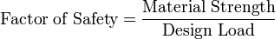
Equation 1 Calculating safety factor
This means a structure with a safety factor of 2 will tail at twice the design load
Safety factors are based upon many different things such as:
- Loads
- Wear estimates
- Strength
- Environmental effects
- Consequences of engineering failure
When the titanic was hit the gigantic mountain of ice, a brittle fracture occurred which meant holes were created, unleashing tonnes of water to torrent in. There were three major safety reasons relating back to material flaws which were incorporated in the material. This brittle fracture occurred due to the freezing waters the titanic was situated in, the speed the vessel was travelling at and the sulphur in the ships material. Researchers have been analysing the samples of ship’s hull and found some interesting findings. The hull sample had sharp wrecked edges so they determined it crushed upon impact, meaning that it did not bend or deform like the inferiority and ductility, which the steel normally has, which means it could have stopped the holes for occurring. Additional flaws have been found in the safety of the rivets which were connected to the plates of the hull. The impact to the vessel resulted in the rivets being scraped off from the side of the hull by the huge ice burg. The rivets used on the titanic should have been stronger this would have increased safety to passengers and reduced causalities.
11 Heat treatement
11.1 Heat treatment (steel)
The steel on the titanic will have been heat treated; this would have created a mass diversity within their micro- structures and properties. When heat treatment is used it uses a phase transformation, during heating and cooling the micro- structure, so it changes in to a solid state.
This diagram is about iron and carbon- diagram established on heat treatment.
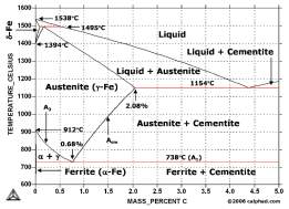
Figure 10 Phase diagram of Fe-c
Cooling rates can vary from each structure type; we can differentiate from the two main heat treatment processes:
- Quenching
- Annealing
Quenching gives non- equilibrium structures whereas annealing creates an equilibrium structure to Fe-Fe3C graph, other than these methods stated their other heat treating methods like stress relieving and normalising.
11.2 Quenching
When this process takes place, the soaking temperature is between 30-50 degrees Celsius, after this cooling occurs really quickly in oil or water. The rate of cooling appears to go beyond its critical value. The critical cooling rate is needed to create a non-equilibrium structure called martensite.
Martensite has many properties which incorporated in its structure. Properties include brittleness as well as hardness.
Quench hardening is a process where the speed will affect the amount of martensite formed, the rate of cooling will depend on the size and materials of the component as well as the quenching type used.
The cooling rate of quenching will not have happened overnight; this cooling happens really slowly when quenching. This will allow time to ensure maximum hardness to the structure.
11.3 Normalising (before rolling plate)
When this process occurs, the soaking temperatures are 30-50 degrees Celsius within austenite; the temperature depends on the content of carbon, after soaking the alloy, which is then cooled in air. This cooling rate will be applied to temperatures of small grain sizes. “A small grain structure increases toughness as well as strength. When normalising takes place we use refinement of grains process this is related with allotropic transformations when heated. During this process, austenite does change the size of the grains when cooling happens”. (Tottin, 2006)
11.4 Tempering (after rolling plate)
The tempering process is carried out to get rid of internal stresses as well as to harden the steel. It’s also tries to remove the brittleness which is caused by the cooling drastic cooling rates.
When the steel is tempered is heated to a temperature approximately around 400-800 degrees, this all depends on the properties which is needed for its intended application. Heat energy lets the carbon atoms to diffuse out of its structure, meaning it will release some internal stresses, if this happens the hardness which I previously mentioned will be severely reduced and ductility will increase. There multiples effects because of this which mean the material has become more resilient as its more tough than it was before and now’s its able to cope with a certain degree of shock. The ship Yard which was making the titanic could have used this heat treating method on the rivets as it would have decreased the brittleness and increase the toughness.
11.5 Thermal equilibrium
“Thermal equilibrium diagrams are present to display, what state the alloys are in at different temperatures. Thermal equilibrium is classed under Zeroth Law Of thermodynamics, this is the indication that the material with significantly high temperature which is transferring warmth to material with a significantly low temperature and then they will get to a point where they will consonantly have to remain the same temperature.” (Nave, 2000)
which therefore means the two materials are in thermal equilibrium with each other.
The image below is a phase diagram which shows the different phases when each material is heated to a certain level and it also depends on the mass percentage of the material used, we know the rivets of the titanic were heated well above austenite temperatures; we can interpret this on the diagram above by looking each phases on the diagram. In the diagram iron for the rivets of the titanic contain 0.21% carbon, as room temperature we have got ferrite, the rivet was heated white hot, this happened within the austenite temperature range which will be about 850 degrees according to the diagram, when this happens the BCC structure turns into a FCC structure and when it cools it turns back to ferrite a BCC structure.
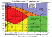
Figure 11 Cast-iron diagram
When we were being talking about ferrous and non- ferrous alloys, thermal equilibrium diagrams are good because they show the changes of what happens in an alloy. Engineers which often study materials, have a look at these diagrams, which results in them realising the typical changes on how the liquid occurs into a solid and this a type of information know as thermal information.
Engineers also observe how two alloys perform on the solidification process, and how they associate with each other, when referring back to the titanic, the hull steel of the titanic it was a mixture of an alloy, which contained carbon and iron.
12 Non-destructive testing
Non- destructive testing is when a series of tests are carried out for a certain material. This is done so we are able to determine if there are any defects in the material without it needing to be destroyed.
12.1 Penetrant test
I carried out a number of tests to prove the sustainability of a range of materials for their intended purpose.
The first test I did is called dye penetrant testing; I did this process on a mechanical component called a casting, weld and finally a forge which is made out of metal. Doing this test will help me to see if there any defects on each one of the individual components, which normally can’t be seen by the naked eye.
This test is done to identify cracks and surface defects, by checking for these impurities in the component as it helps us to see if the component is fit for use, as in industry any component which is not up to standard will be scraped, as this can affect the production line further on.
These are steps below that we did on the dye penetrant casting:
- First, I got some solvent and started to clean the work piece, this is done thoroughly and all-round the piece, the purpose of doing this is to make sure the dirt and dust on the cast doesn’t affect my results.
- The second step is to take a visual inspection of the piece to see if you can see any defects to the piece.
- Apply the die, make sure you are about 30cm away from the work piece you are spraying it to, as adding to much won’t make difference, make sure the whole cast is covered and the sides. Let it dry for 4-8 mints.
- Now use a dry wipe to remove the die, this process can take about 3-5 minutes to clean the cat depending on size.
- Next, use a solvent wipe to remove excess which the dry wipe failed to do, with the dry wipe you couldn’t take all the dye off the cast, that’s the reason why we use a solvent wipe again, this to make sure the dye is totally off.
- After doing the previous step, I added the developer, the purpose of adding this is to make any of the defects to the material visible.
- Check for any impurities and surface defects in the cast and record them down below, after doing this make sure you clean the cast with the solvent cleaner.

Figure 12 Processes of dye penetrant application
12.2 Magnetic particle testing
The second test I did is called magnetic particle testing; there are many different types magnetic practical testing these was known as:
- Cable wraps
- Prods
- Bench units
- AC and DC Yoke
- Permanent magnets
- Induction coils
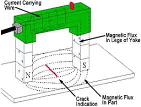
Figure 13 Ac yoke
When carrying out magnetic particle testing with association with lavender, we had used an engineering instrument called electromagnetic yoke, this process involves a longitudinal electromagnetic field being produced through the electromagnet on which it gives an indication on the surface of the material if there were any cracks or defects on it, I did this by spraying chemical cleaning solvent on to the metal (cast) and then wisely assigning the electromagnetic in a horizontal direction on the road to where I were examining any defects which may have occurred, the scrutinizing area is located in a circle between tow poles of the magnetic on where by I carried out our inspection for any defects.
13 Destructive testing
At Sheffield Hallam University, we did a series of destructive testing; the descriptions of the tests are visible below:
13.1 Impact Testing
In this experiment, we use different metals and put a little cut in them so that impact testing machine has a starting point. We test all 4 (50 mm long) metals: low carbon steel, pure zinc, brass and aluminum alloyed at 5 different temperatures: -78, freezing point, room temperature, 50C and boiling point. One by one we put the metals inside the impact testing machine and line the metal there the cut is with the (2 mm) notch and close the grad and press start, the hammer comes from 150C angle with energy of 50J.
13.2 Hardness Testing
In this experiment, we polish the 4 metals and place them in the machine and press start and the machine makes the diamond shape on the metal and then we us the machine to measure the diamond from both side and write the results in my book.
13.3 Tensile Testing
In this experiment, we measure the elongation and the radiation then we place the metals inside the machine and reset all the reference values to 0 and press start and when the metal breaks take it out and measure the elongation and radiation and note it down in your book.
14 Results
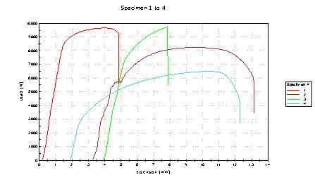
Figure 14 Tensilee Stress graph of different material specimens
|
|
|
|
|
|
|
|
|
|
|
|
|
|
|
|
|
|
|
|
|
|
|
|
|
|
|
|
|
|
|
Table 3 Different temperatures, the specimens were
t
|
|
|
|
|
|
|
|
|
|
|
|
|
|
|
|
|
|
|
|
|
|
|
|
|
|
|
|
|
|
|
|
|
|
|
|
|
|
|
|
|
|
|
|
|
Table 4 Statistics showing the individual material properties before fracture.
14.1 Impact test result analysis
From the impact test, mild steel was the best material to use, because when the temperature was at -75 degrees, the piece impact strength of 45J whereas all the other materials were less resilient by force applied, even when it was +100 degrees it was leading the race as it got a reading of 50J. Brass got a score of 23J at the temperature of -75 and when it was 100 degrees+ it got a score 18J. To conclude, from the impact test done, the designers of the titanic were right to use mild steel as it was resilient to impact, if they had use brass or any other material stated above, the chances of the ship sinking quicker would have increased, this proven to be fact as the materials stated above couldn’t with stand the shear force applied in this test, so they got an lower score. If mild steel wasn’t available they would have had use brass, however this would have made the vessel less resilient and would have sunk quicker as it hit the iceberg.
14.2 Hardness test analysis
Doing the hardness test, we came across some interesting findings. Specimen 1 load started to dramatically increase to a load 9000 and then it stayed the same and then the load dropped to 5000 with an extension of 4.5mm. Concluding from the results specimen 3 would have been ideal to use as the hull of the titanic, on the graph specimen 3 gradually starts to increase with the extersion staying the same for a bit and starting to decrease 7500. The hull of the titanic would have benefited from using specimen as the load increased and stayed steady for the longest period of time before decreasing. Although specimen 1 load increased dramatically it shouldn’t be used on the ship’s hull because the hardness of material for specimen wouldn’t have lasted long whereas specimen gradually disappears.
14.3 Tensile test analysis
From the tensile test the 0.1% steel was the best according to test results, it had the longest elongation percentage of 37 and area of red 57. The hull of the titanic should have been form this material, as the titanic would have benefited from the properties, it has got to offer but if this material wasn’t available, they would to use a different type, then I would recommend stainless steel to create the hull because, in the result below the hardness and strength is higher than the results given to me about mild steel, stainless steel would be better as it provides extra material properties which mild steel struggles to give.
15 Conclusion
In conclusion specimen one (mild steel) is the best because on three of the tests which were carried out, this on the sample it came on top all three tests compared to any other materials used in the test. This means sample one it is more inferior and has more properties which resulted in the material showing its end product when put to the test. Using mild steel was the best option around that era because development of materials was limited and they used skills sets and processes which we see as outdated. Alternatively, back then they had brass this could have been used to create the titanic, although it’s not as strong and robust as mild steel but it would have done its job, on the strength test for brass it came second and wasn’t far off from taking first place, so it would have been a good substitute if mild steel wasn’t available.
16 Non-destructive testing result analysis
16.1 Casting results
There weren’t any defects nor cracks visible from the test I did on the cast, however the public servant from lavender said “there are no defects apparent however the black was hugging in to the edges of the circular cast is an indication something is wrong and wouldn’t come out”, this component needs further investigation into the cast, so we can rule out any complications before its available for use. This shows how important to use different types of testing on this component so we can investigate the problems at early stage so therefore the risk further on is minimized.
16.2 Forging results
When carrying out, the magnetic particle test on the forging I uncovered two deep cracks which weren’t apparent before we did the test. These cracks are now noticeable from the top and bottom of the forging. The defects are 13mm away from the top and 62mm is the actual size of the cracks which is now obvious. The results of this test need to be taken further so we can identify the problems of this forge, doing these test have helped us identify the problems where as a visual inspection would have not have been able to see the cracks, so therefore we would have assumed the forge is fine, these are reasons why we use a series of different, which eventually give us explanation of what’s wrong with the component and how it happened.
16.3 Welding results
As we were carrying out the magnetic particle test on the component piece which is most commonly known as a weld, whilst an analysing the findings we exposed the flaws which were unnoticeable in the weld before we did the test. The weld had scarring and crack which was 115mm away for the diameter of the square piece. The weld is either not strong enough or has a flaw in the way it was created, to be on the safe side this piece is not suitable for its intended application.
17 Conclusion
At this stage of the investigation I carried out two different types of non- destructive testing on three dissimilar kinds of components, I did these tests so I could find out if there anything wrong with any of the components, as we all know now that there were cracks and surface defects on nearly all the components, testing these components have helped us to find out whether they are fit for their intended application. Spotting these problems early on will have resulted is less hassle further on in the line, so now further testing can be done to find the root cause of the problem, these are the reasons why non- destructive testing is important as it allows us to see, what can’t be seen.
Bibliography
Bassett, v. (1998). Causes and Effects of the Rapid Sinking.
Britanica, E. (2008). Open-hearth process.
Felkins, K. (1998). The Royal Mail Ship Titanic: Did a Metallurgical Failure Cause a Night to Remember? JOM, pp12-18.
Gannon, R. (1995, February). What Really Sank The Titanic.
Leighly, D. P. (2008). Steel of Titanic. pp6-7.
Manufacturing, T. L. (no date). The Library Of Manufacturing. Retrieved from http://thelibraryofmanufacturing.com/privacy_policy.html
Nave, D. R. (2000). Hyper Physics. Retrieved from http://hyperphysics.phy-astr.gsu.edu/hbase/hframe.html
Supermarkets, M. (2014, September). Retrieved from https://www.metalsupermarkets.com/difference-between-hot-rolled-steel-and-cold-rolled-steel/
Tottin, G. (2006). Steel Heat Treatment. CRC Press.
Cite This Work
To export a reference to this article please select a referencing stye below:
Related Services
View all


Related Content
All TagsContent relating to: "Maritime"
Maritime is something relating to the seas and oceans. The term is commonly used in nautical and seaborne trade matters. Not to be confused with “marine” which relates specifically to the seas, oceans and the life within them.
Related Articles

DMCA / Removal Request
If you are the original writer of this dissertation and no longer wish to have your work published on the UKDiss.com website then please: