Implementation of Hybrid VPN model in Cost-Effective Enterprise Networking Solution
Info: 13748 words (55 pages) Dissertation
Published: 13th Dec 2019
Tagged: Computer Science
“Implementation of Hybrid VPN model in creating Cost-Effective Enterprise Networking Solution”
The digital era is finally taking its shape with more and more refinements in Internet technology day by day. There has been a massive growth of Internet over the last decade and many businesses are relying upon their e-businesses to target their right customers separated by geographical boundaries. Cloud services are heavily depended by businesses to effectively deliver their services by keeping their costs low and transparency high with their stake holders.
There are phenomenal expectations by e-businesses to run their infrastructure more secure, scalable, reliable and manageable. Today’s enterprise infrastructure are characterized by geographical coverage, end to end connectivity with no hassles around keeping security, scalability, performance and cost as a prime factor of delivery.
This study is on various VPN models with various vendor proprietary protocols that can be designed to deliver a Hybrid VPN model to achieve cost effective enterprise managed networking solutions. The current practice of connecting Arrow branch offices over the single leased line connection leaves the office vulnerable to the network outages. A failure of that single connection is extremely costly to a company unless there is no appropriate backup network facilities. Hence the need for better WAN engineering and optimization became necessary to identify, prioritize and load balance traffic with an appropriate backup network paths.
Broad Academic Area of Work: Computer Networks, Internetworking Technologies.
Key Words: VPN, IPSec, DMVPN, Managed Enterprise Infrastructure.
Signature of the Student Signature of Supervisor


_____________________ ______________________
Name: Alok Hiriyur Name: Shafi Kowsar Mohammad
Date: 31-March-2017 Date: 31-March-2017
Place: Pune Place: Bangalore
ACKNOWLEDGEMENT
I take this opportunity to express my profound gratitude and deep regard to my supervisor Mr. Shafi Kowsar Mohammad, Arrow Electronics India Pvt Ltd, Bangalore for his exemplary guidance, monitoring and constantencouragement throughout the course of this Dissertation work.
I extend my sincere gratitude to Mr. Sathish Kumar Jaiswal, Xoriant Solutions, Pune for providing tips and suggestions throughout the course of this dissertation.
I would like thank my guide Mr. Mahadev Anant Gawas of BITS, Goa Campus for providing expert thoughts and suggestions throughout this dissertation work.
I am grateful to my friends and teammates who assisted in technical and general ways, and helped preserve, protect, and defend my general sanity.
The support, understanding, encouragement, and wisdom of these individuals and groups helped sustain and inspire me throughout.
TABLE OF CONTENTS
2.1 MPLS (Multi-Protocol Label Switching) VPN Model: (RFC 2547, RFC 4364)
SSL VPN – Secure Socket Layer.
GRE – Generic Routing Encapsulation
DMVPN – Dynamic Multipoint VPN
Redundancy and High Availability using HSRP
Checklist of items for the Final Dissertation Report
List of Figures:
Figure 1. 1: Source to Source VPN
Figure 1. 2: VPN Classification.
Figure 1. 3: Layer-2 Overlay VPN model, Source: Cisco Press
Figure 1. 4: Overlay VPN Model, Source: Cisco Press
Figure 1. 5: Layer-3 Overlay VPN model, Source: Cisco Press, VPN models.
Figure 1. 6: Peer to Peer MPLS VPN Model, Source: Cisco Press
Figure 1. 7: Site to Site VPN, Source: Cisco Press, Formation of 3 logical tunnels.
Figure 1. 8: SSL VPN for Mobile Users
Figure 2. 2: MP-BGP Update Message Type. Source: Cisco Press, Packet Life
Figure 2. 3: MPLS VPN Overview.
Figure 2. 4: MPLS Label, Source: NOA
Figure 2. 5: Inner and Outer Label, Source: Cisco Press
Figure 3. 1: Cisco Express Forwarding. Source: Cisco Press, Website: cisco.com
Figure 3. 2: Router Logs showing the CEF, Prefix mappings to Next hop and exit interfaces.
Figure 5. 1: IPSec Tunnel Mode
Figure 5. 2: IPSec Transport Mode
Figure 5. 3: IPSec Tunnel & Transport Mode
Figure 5. 7: Filtering interesting traffic using ACL (Access Control Lists).
Figure 5. 8: Diffie Hellman key exchange pattern
Figure 6. 3: Point to Point GRE
Figure 6. 4: Tunnel Mode IPSec over GRE
Figure 6. 5: Transport Mode Header IPSec over GRE
Figure 7. 1: Configuration: Configuring DMVPN Hub “New York”
Figure 9. 1: HSRP Configuration Setup
Figure 11. 1: Hybrid VPN Design -1
Figure 11. 2: Hybrid VPN Design -2
Figure 11. 3: High-level Design – Hubs
Figure 11. 4: High level design – Spokes
Figure 11. 5: Low-level diagram at spokes
Chapter – 1
Introduction
The Network Technology that we are using at Arrow Electronics to connect different ‘high priority’ branches within the same region is through the leased line point to point circuits. They are highly expensive and incurs huge operational costs. Leased lines are a private point to point link hired from the service provider to connect two branches. While, MPLS is more scalable solution where multiple branches can be connected by full-mesh topology under a single service provider cloud. Customers use VPNs primarily to reduce operational costs. VPNs provide the same security to that of traditional point to point circuits as it has a security mechanism to prevent unauthorized users penetrating into the network securing the data sent over the unsecure channel.
Due to ever growing business operational demands, IT professionals are facing challenges day by day to deliver wide ranges of services. The most important goal of the following project is to achieve seamless secure network connectivity through a hybrid VPN model across 400 plus Arrow Electronics branches in the Globe keeping the cost budget as low as possible without compromising on;
- Efficiency & Performance regardless of the type of data: Dynamic Path Control automatically balances the traffic, maximizing the WAN investment and isolating an erratic connection before it impacts the application. Reduce costs by replacing expensive leased line connections with aggregated, more affordable Public Internet links.
- Security: Networks that are constructed using advanced encryption technologies.
- Scalability: Technology should be adaptable dynamically with respect to the growth of business.
- Fault Tolerance: Prevent problems before they occur by detecting signs of a failing path and proactively switching traffic to a backup path.
- Ease of administration: Improve availability by adding a secondary connection without wasting any bandwidth.
- Simplicity: Easy to understand in order to isolate the problems on the go.
Hence, I will begin by showcasing the different kinds of VPNs and vendor proprietary protocols that are in great demand in today’s emerging markets due to the growing cost concern. In the upcoming chapters, I will showcase an ideal working model to interconnect the product based organization like Arrow Electronics branches spanning globally across 400 locations and also the future scope to be ready for the Software-Defined-Networking.
1.1 – The VPN Terminology
VPN is virtualized extension of the private network in the unsecure public internet cloud maintaining security compared to that of dedicated point to point circuits using advanced encryption and tunneling protocols to connect source & destination or to multiple destinations.
The figure 1.1 below represents the logical point to point encrypted tunnel connecting two different customer sites across the different geographies over the unsecure public network (Typically the Internet).
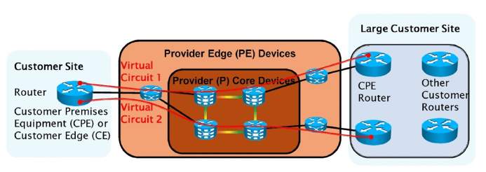
Figure 1. 1: Source to Source VPN
Source: Cisco Press, Site to Site VPN.
1.2 VPN Categories
VPNs are classified into four categories namely;
- Trusted VPN: The legacy VPN which are ‘trusted’ by customer, Leased from the Service Provider. Customer’s responsibility is to implement security policies and trust their service provider that their traffic is not interfered. It is not trusted because anyone with the access to the physical device can compromise the customer’s traffic.
Example: Frame relay, ATM, X.25.
- Secure VPN: While the security being a concern, advanced encryption and decryption methodologies are used on both ends of the node to secure the information passed between them.
Example: IPSec, GRE, DMVPN, L2TP, SSL VPN.
- Hybrid VPN: A well combined standards of Secure and Trusted VPN where a customer controls the security implementations and service provider guarantees the trusted aspect.
Example: MPLS + IPsec over GRE.
- Service Provider provisioned VPN: A VPN that is designed, implemented and administered by a service provider.
1.3 VPN Implementation Models
VPN services can be offered in 2 different models of implementation;
- Overlay Model: The service provider establishes virtual point to point links.
- Peer to Peer Model: The service provider participates in customer routing.
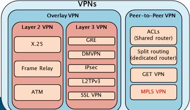
Figure 1. 2: VPN Classification.
Source: Cisco Press, Classification of VPN Models.
Overlay Model:
Overlay VPN models are categorized into Layer 1, 2 and 3 models based upon their implementations and technology which will be explained in this section.
Overlay models provide private point to point connectivity between the customer sites across the service provider’s shared wide area network infrastructure. Overlay VPNs are implemented at multiple layers of OSI model at which they work at. They are, Layer-1 using the leased lines, layer-2 using the Frame Relay virtual circuits having DLCI numbers or through legacy ATMs or X.25 virtual circuits and layer-3 using GRE, IPSec, DMVPN, SSL VPN or L2TP(Layer-2 Tunneling Protocol).
In the overlay model, customer routers will be running the routing protocols across both the ends by the virtual circuits provisioned by service provider. The service provider will have no knowledge about the network architecture of their customers.
The figure1.3 below illustrates how the Layer-2 Overlay VPN can be implemented between source and destination using the virtual circuits by the technologies such as x.25, Frame relay or ATM.
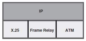
Figure 1. 3: Layer-2 Overlay VPN model, Source: Cisco Press
The figure 1.4 below illustrates the overlay model provisioned by the service provider connecting the customer’s Hub location Bangalore through their frame relay virtual circuits VC#1 and VC#2 to their spokes Pune and Delhi.
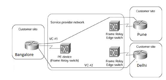
Figure 1. 4: Overlay VPN Model, Source: Cisco Press
Note: Layer 1 and 2 overlay VPN models are mostly deprecated in the modern enterprises.
Layer-3 Overlay VPN Model:
The figure 1.5 below illustrates Layer-3 Overlay VPN model implementations where VPN is implemented IP over IP traditionally referred to as IP tunneling. These IP tunnels are established with Generic Routing and Encapsulation (GRE), IP Security (IPSec), Dynamic Multipoint VPN (Cisco proprietary DMVPN) and Secure Socket Layer VPN (SSL VPN for Remote Access) etc. L3 Overlay VPNs are discussed extensively in the following chapters.
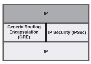
Figure 1. 5: Layer-3 Overlay VPN model, Source: Cisco Press, VPN models.
Advantages of Overlay model:
- Easy to Implement.
- Service Providers do not participate in customer routing.
- Customer network and service provider’s network are isolated.
Disadvantages of Overlay Model:
- Not a scalable solution for architects, policies can vary between site to site exchanging customer’s traffic. (Bandwidth may have to be configured on site to site basis.)
- Expensive for ISPs: In order to provision this, ISPs should implement fully meshed point to point circuits across geographical boundaries.
- It incurs encapsulation and encryption overhead on the VCs resulting in bandwidth wastage, increased router CPU cycles (IPSec over GRE).
Peer to Peer VPN Model:
Peer to peer VPN model was introduced to alleviate the problems faced in the Overlay VPN model, it guarantees optimal routing between many customer sites. It is easier to scale up the infrastructure like provisioning new site. Easier to provision the bandwidth as it can be provisioned using CAR (Committed Access Rate) and CDR (Committed Delivery Rate) both inbound and outbound. Customer routes are exchanged with service providers who participate in the routing. The service provider undertakes all the complexities to provide easier end to end connectivity to the customer’s implementation.
The figure 1.6 below illustrates the peer to peer model provisioned by the service provider connecting the customer’s Hub location Bangalore through their MPLS VPN circuits to their spokes Pune and Delhi.
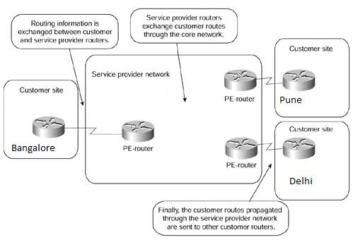
Figure 1. 6: Peer to Peer MPLS VPN Model, Source: Cisco Press
Advantages of Peer to Peer Model:
- Routing between different customer sites are optimal.
- Multi-tenancy of customers across provider’s edge router isolated using VRF.
- Circuit capacity sizing (Bandwidth Allocation) is not an issue unlike Overlay model.
- Simpler routing configurations for customers.
Disadvantages of Peer to Peer Model are:
- As the Service providers participate in the customer’s routing ACL (Access Control Lists) filters need to be applied across customer’s as well as provider’s routers. More filters means more CPU overheads in the router.
- Customers are reliant on service providers for the convergence.
- Complex configuration at service provider’s end as they need to ensure security of every customer while multi-homing many customer’s traffic across their routers. (VRF, Virtual Route Forwarding should be used to segregate customers).
1.4 VPN Types
In the ongoing IT era, organizations have been increasingly dependent on the VPNs due to its features such as lower cost & flexibility of upscaling, several number of VPN protocols are developed by vendors and manufacturers. IEEE and IETF have been further standardizing it to fit into the dynamic nature of exponential growth of Internet. Thus the following protocols that are discussed in this study are GRE, SSL VPN, MPLS VPN, IPSec and DMVPN.
The VPN protocols can also be categorized in two major groups.
- Site to Site VPNs.
- Remote Access VPNs.
Site to Site VPNs:
Site-to-site VPNs are implemented to interconnect corporate branches with their remote sites via VPN through various models such as Overlay L1, L2, L3 and Peer to Peer models.
Site-to-site VPNs are also called as Intranet VPNs or Extranet VPNs. [8]
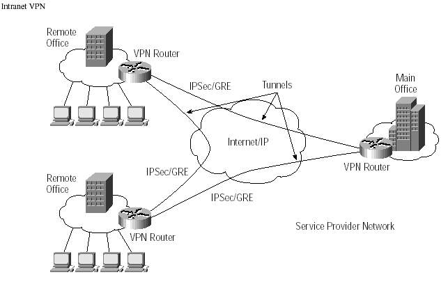
Figure 1. 7: Site to Site VPN, Source: Cisco Press, Formation of 3 logical tunnels.
Intranet VPNs can simply be the connection between the headquarters and the remote branch belonging to single network infrastructure. User access between Intranet sites can be implemented with site to site encryption and encapsulation within the customer premises equipment. Extranet VPNs refers to connection between the organization and service provider such as SaaS, PaaS, and IaaS etc. User access between these sites should be securely controlled by both the parties at their respective ends. Generally, extranet VPN’s are connected over to the firewalls at both ends (Customers, Clients or Service providers) where tough security policies are implemented.
Remote Access VPNs:
VPNs that are deployed to the individual remote users to directly connect to their corporate networks. This is made possible using SSL (Secure Socket Layer) VPNs using client side application and web browser for the remote authentication.
SSL provides both encryption and authentication services.
Figure1.8 below illustrates the SSL VPN providing virtual encrypted connectivity between the mobile users and corporate network.
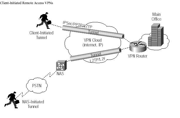
Figure 1. 8: SSL VPN for Mobile Users
Chapter – 2
VPN Models
2.1 MPLS (Multi-Protocol Label Switching) VPN Model: (RFC 2547, RFC 4364)
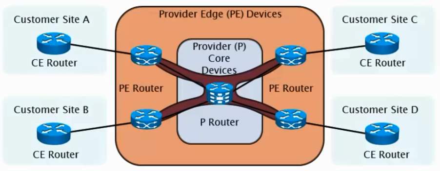
MPLS which is often referred as Layer 2.5 as it works between the Datalink layer and the Network layer of the OSI model. MPLS VPN model combines the best of Overlay model as well as Peer to Peer Model. Customer’s security and segregation compared of that of Overlay Frame Relay circuits are achieved using Virtual Route Forwarding (VRF) tables. Each customers has their own routing table instance on the Service provider’s routers. Label Switching is enabled on the Service Provider’s core router (P router or Route Reflectors).
Source: Cisco Press
From the Figure 1.9, CE router exchanges the routing information to the PE router with a normal IP packet like that of peer to peer model. Inside the PE router, the data from the CE router will be Label Switched across another PE router. At the PE router, Service providers maintains the separate VRF table (Virtual Route forwarding) for every customer. In order to exchange the routes across PE routers forming VPNV4 Peering among the other PE routers or to the Route Reflector routers (P Router) in the image above.
- P router forwards the packets to PE based on label.
- P and PE router share the same IGP (Interior Gateway Protocol, OSPF, EIGRP) etc.
- PE routers uses separate customer specific IP routing table (distinguished by VRF) with CE and MPLS labels with P routers.
VRF: Virtual Route Forwarding
VRF is a concept of Multi-Homing or Multi-Tenancy of customers inside the Service Provider’s Edge router. Each VRF acts as a virtual independent router separated by a logical interfaces inside the router. It can run its own routing protocols as VRF has a separate Routing Plane and a Forwarding Plane.
Each customer’s routes are learned through the VRF routing table on the PE. The backbone routes inter-connecting different PE’s are generally configured by IGP, BGP or label switched among each other by service provider.
Note: Only few routing Protocols support the concept of VRF, they are RIP, OSPF, EIGRP, ISIS and BGP.
MPLS VPN: Control Plane: VPN route propagation
It contains 2 tables that are RIB (Routing Information Base using Routing protocols) and LIB (Label Information base using Label Distribution protocol).
The layer 3 routing information and the routing protocols are managed by control plane. Between the Provider core routers, it runs the LDP (Label Distribution Protocol) for the faster switching of data at layer – 2 exchanging the labels.
The control Plane for MPLS VPN is Multi-Protocol BGP. MP-BGP customizes the VPNV4 customer routing information as per the VRF configured at the PE router.

Figure 2. 2: MP-BGP Update Message Type. Source: Cisco Press, Packet Life
MP-BGP Update message contain RD (Route Distinguisher), RT (Route Target), IPv4 Header and Label. 8 byte header information called Route Distinguisher is prepended to the 4 byte IPv4 address in order to distinguish or segregate the IPv4 address to be globally unique BGP VPNV4 address within the Service Provider network at the PE. RD is configured inside the VRF at the PE router.
Route Distinguisher (RD) is used to keep the Customer’s routing tables unique and Route Targets (RT) are used to forward routes between the specific VRF’s and VPNs.
Route Distinguisher
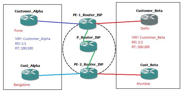
Figure 2. 3: MPLS VPN Overview.
Example:
Customer Alpha: 1:1:10.1.0.0/24
Customer Alpha: 1:1:10.2.0.0/24
Customer Beta: 2:2:10.1.0.0/24
Customer Beta: 2:2:10.2.0.0/24
Note: In the above example Route distinguisher is prepended to IPv4 prefix. Both, the Customer Alpha and Beta has the same IP prefix. Even then the following routing is segregated using the RD in Service provider’s network. How? By using the RT (Route Targets).
Route Targets
Having segregated the customer’s prefixes as BGP VPNV4 unicast address, how do other PE routers identify which routes belong to which customer? That is achieved using Route Target. RT (Route Target) identifies the VRF for the received VPNV4 prefix. Each VRF is configured with set of RT to identify and forward to specific VPNV4 route.
Example:
ip vrf Customer_Alpha
rd 1:1
route-target export 100:100
route-target import 100:100
!
ip vrf Customer_Beta
rd 2:2
route-target export 200:200
route-target import 200:200
!
int gi0/0
description connection to Customer_Alpha
ip vrf forwarding Customer_Alpha
int gi0/1
description connection to Customer_Beta
ip vrf forwarding Customer_Beta
In the example of RD and RT configuration above, Customer Alpha has Route Target value 100:100 to routes from Customer Alpha prefix segregated by RD across the other PEs in a different geographical locations, the other PE router checks the vpnv4 BGP table and import and export the routes having the Route Target value 100:100 and add them into a separate Virtual Routing & Forwarding (VRF) table for Customer Alpha. Likewise, for the Customer Beta, the PE routers exchanges the information logically separating the customers across the provider’s backbone networks.
Summary:
- PE router receives an IPv4 update from Customer router via eBGP or EIGRP or OSPF or ISIS etc.
- PE router translates it into BGPVPNv4 address and constructs MP-iBGP UPDATE message
- It associates the RT values exporting 100:100 in case of Customer_Alpha inside the VRF configuration.
- It further assigns a label and does the label switching inside the PE’s (For faster forwarding).
- On the receiving end of PE router, it checks the Route Target 100:100 if configured locally as import RT as given in the configuration within the VRF, if Yes, then
- The receiving PE router translates VPNV4 prefix into IPV4 prefix to forward it to the Customer_Alpha.
- It further updates the VRF CEF (Cisco Express Forwarding, Explained Shortly) table for the Customer_Alpha’s prefix with a unique label for a faster MPLS forwarding between the PE’s.
MPLS VPN Forwarding Plane: VPN packet forwarding
The Data or a Forwarding plane contains LFIB i.e, Label Forwarding Information Base. LFIB contains a 20 bit label value field inside the MPLS header as per the below diagram which defines where the label needs to be forwarded.
Referring to the Figure 2.1, MPLS VPN maintains two separate forwarding tables that are Global forwarding table and VRF specific forwarding table.
- Global Forwarding Table stores next-hop routes with associated labels.
- PE to Provider Core routes are typically learned through labels LDP (Core Label Distribution Protocol).
- In the VRF Table, VPN routes are learned through BGP.
- Labels are learned through MP-BGP as explained above.
Referring to the figure 2.3, Customer_Alpha from Pune tries to communicate to its Branch in Bangalore, the PE-1_Router_ISP prepends two MPLS labels (Headers) destined to Bangalore.
Referring to figure 2.4 and 2.5, Outer Label and Inner Labels are prepended into the IPv4 header. Outer Label is learned through LDP (Label Distribution Protocol) corresponding to their IGP protocol. It is used for switching packet inside the MPLS networks. Inner label is learned via MP-BGP corresponding to VPNv4. Inner labels are used to identify the VPN.

Figure 2. 4: MPLS Label, Source: NOA
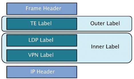
Figure 2. 5: Inner and Outer Label, Source: Cisco Press
MPLS uses 32 bit label header inserted between Layer 2 and Layer 3 of the OSI model containing:
- 20-bit label.
- 3-bit experimental field.
- 1-bit bottom stack indicator and
- 8-bit TTL field.
Chapter – 3
Cisco Express Forwarding
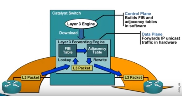
Figure 3. 1: Cisco Express Forwarding. Source: Cisco Press, Website: cisco.com
Cisco has developed a proprietary protocol for forwarding packets (Layer-3) called Cisco Express Forwarding. A faster layer-3 switching methodology. Traditionally, a router performs a route table lookup to forward traffic from source to destination. Every time when router does route table lookup to forward traffic, it may lead to latency and congestion.
Thus CEF is introduced to optimize the router to make it able to forward packets much faster.
How?
Before a packet arrives into the network, Router maintains layer-3 routing table into a separate hardware. Hence it can provide a wire speed lookup compared to that of legacy software based route table lookup process.
CEF segregates Control Plane and Data Plane as an independent entity.
Control Plane contains information such as routing protocols and runs on the route processor. It performs the normal route table lookup first and builds FIB and adjacency table (maintaining the exit interface of the router) in the software and then copies the routing and adjacency entries into the Hardware based Data Plane.
Now, Data Plane contains Forwarding Information Base (FIB) and Adjacency Table (Exit Interface mapping to specific route). Thus router need not have do the route table lookup to forward the packet thereby greatly reducing the latency and CPU overhead. Thus it forwards in wire speed based upon the information inside the Data Plane.
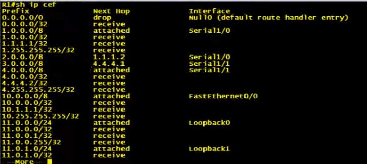
Figure 3. 2: Router Logs showing the CEF, Prefix mappings to Next hop and exit interfaces.
Chapter – 4
SSL VPN – Secure Socket Layer.
(Full Tunnel Mode for Remote Access VPN)
SSL provides authentication, privacy and integrity by its cryptographic framework. SSL VPNs are mainly used for Remote Access. It can run on any of the Web browser, it encrypts the traffic using Public Key Infrastructure (PKI). It allows users to connect remotely to their organization network from their Home Internet. SSL VPN clients negotiate a connection using TLS (Transport Layer Security). Netscape developed the SSL and now IETF has adopted and redefined developing SSL to TLS standard (RFC2246).
Web based portals allow users to authenticate to SSL VPN Concentrator.
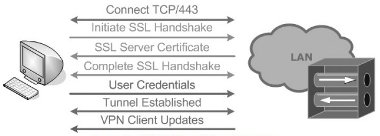
A web browser connects to SSL VPN Concentrator address secured with SSL (HTTPS), A TCP connection to the port 443 is established to initiate SSL handshake between the client and the VPN concentrator to allow SSL protocol handshake. Remote client is typically authenticated by LDAP or RADIUS or TACACS+ server. SSL certificate is then validated by the concentrator to initialize the SSL session for the remote access.
Figure 4.1 below refers to the authentication process in SSL Remote Access VPN in full tunnel mode. Source: packetlife.net
The Cisco solution enhances the SSL VPN functionality to provide many deployment modes that include the following, [8]
• Clientless mode: Provides secure access to corporate resources, specifically web and e-mail servers, without loading any applets or other clients. [8]
• Thin client mode: Provides access to most of the TCP-based protocols, such as SMTP, POP, Secure Shell (SSH), Terminal, and Telnet by loading a Java applet on the client machine. [8]
• Full tunnel mode: Provides full access to corporate resources as if you were connected directly to the network. This mode requires you to use a dynamically downloadable SSL VPN client before access is granted. [8]
Chapter – 5
IPSec VPN – IP Security.
IPSec is collection of protocols developed by IETF to allow communication in a secure manner by authenticating and encrypting each IP packet of a session in the public unsecure network (Internet). IPSec is dynamically scalable to the growth of the business as it can accommodate large networks. IPSec can be implemented in Cisco IOS as well as Firewalls from different vendors such as Cisco, Palo Alto, Juniper, PIX and Checkpoint.
IPSec is the only standard Layer – 3 technology that provides:
Confidentiality: Ensures no one reads the information, uses several encryption algorithms to encrypt the clear text data into encrypted format. (Discussed Later)
Data Integrity: A method where a particular data is not modified in transit, Runs a Hashing algorithm at both the ends and validates by comparing the data sent and received.
Authentication: Method of verifying the peers by using some password based authentication in an Internet channel.
Replay Detection: Ensures packet receives only once tracking through its sequence number, receiver rejects old or duplicate packets. It is a mechanism to defend DDoS (Distributed Denial of Service) attacks.
Thus it makes the IPSec as secure as leased line point to point connections.
5.1 IPSec Modes
IPSec can be used to build Site to Site as well as Remote Access VPN.
However, there are 2 modes of IPSec Implementations, They are:
Tunnel Mode:
In the Tunnel mode, the entire IP packet is protected by IPSec encryption.
It adds a new IP header and sends to the VPN end point.
Commonly used in site to site implementation where there is Firewalls or Advanced routers as a gateway device
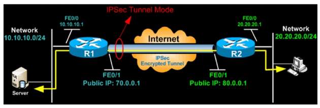
Figure 5. 1: IPSec Tunnel Mode
Source: Firewall.cx [10], IPSec Tunnel Mode.
Transport Mode:
It is commonly used between clients to site end to end VPN setup. E.g.; Client to Server or Remote Desktop.
It encrypts only the payload and ESP trailer.
IP header of the original packet is not encrypted.
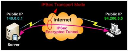
Figure 5. 2: IPSec Transport Mode
Source: Firewall.cx [10], IPSec Transport Mode.
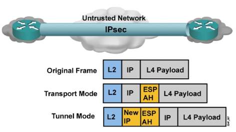
Figure 5. 3: IPSec Tunnel & Transport Mode
Source: Network Online Academy, IPSec Transport Mode.
IPSec Process
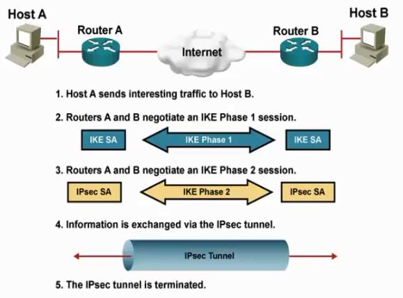
Source: Network Online Academy
The entire IPSec process goes into a five different steps as defined above.
IPSec Incorporates 3 major protocols creating the robust security framework in 2 Phases, They are;
Phase – 1: Setting up ISAKMP (Internet Security Association Key Management Policy) Security association between peers. Secure channel to peer communication (VPN Endpoints) happens in phase – 1.
Internet Key Exchange (IKE):
- Provides framework for negotiating security parameters.
- Establishment of Authenticated keys.
Phase – 2: Negotiating IPSec Security association parameters. Actual encrypting and application of security and authentication policies happens in phase – 2.
Encapsulating Security Payload (ESP):
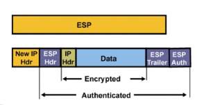
Source: Firewall.cx [10]
- Provides framework for encrypting, authenticating and securing of data.
- Works on IP Protocol Number 50.
- Has more overhead which offers Authentication, Data Integrity and Anti-Replay mechanism.
Authentication Header (AH):
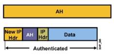
Source: Firewall.cx [10]
- Provides framework for authenticating and securing data.
- Works on IP Protocol Number 51.
- It adds less overhead and also offers Authentication, Data Integrity and Anti-Replay mechanism.
- AH does not support encryption.
First step is to identify and define the interesting traffic required for peering. (Site to Site VPN).
ACL is set filtering the routes destined to Pune from Bangalore as Interesting Traffic to which IPSec needs to be applied. Traffic destined to Internet are sent in clear-text format.
Bangalore(config)#access-list 100 permit ip 192.168.1.0 0.0.0.255 192.168.2.0 0.0.0.255
Bangalore(config)# permit any any
Pune(config)#access-list 100 permit ip 192.168.2.0 0.0.0.255 192.168.1.0 0.0.0.255
Pune(config)# permit any any
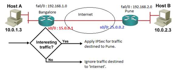
Figure 5. 7: Filtering interesting traffic using ACL (Access Control Lists).
In the Phase – 1, the policies defined on one of the end point should reflect the same in other end point as well, only then the IKE tunnel will form between the endpoints. (Internet Key Exchange).
- In ISAKMP policy, we need to define the authentication, encryption policies and hashing algorithm in order to build an ISAKMP secure channel between the VPN endpoints.
- DES, 3DES, AES encryption algorithm are used for the data encryption between end points. AES encryption is stronger than 3DES and DES.
- Diffie-Hellman algorithm is used to establish the secret key between VPN end points.
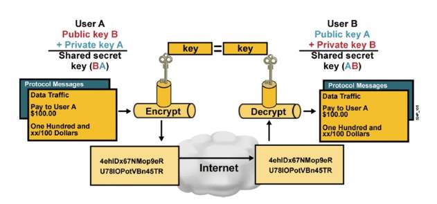
Figure 5. 8: Diffie Hellman key exchange pattern
Source: Cisco Press, Diffie Hellman Key Exchange pattern.
- MD5 and SHA1 algorithms are used for hashing to provide data Integrity.
Authenticating VPN endpoints is done through Pre-shared keys or RSA Signatures. Pre-shared keys should match at both the end points else, the VPN end points do not peer.
On Both Bangalore and Pune Routers:
Step – 1: IKE Phase – 1 configuration:
Enable ISAKMP policy on both the end points.
Bangalore(config)# crypto isakmp enable
Pune(config)# crypto isakmp enable
Step – 2: Define Encryption, Authentication and Hashing algorithms to be used inside the ISAKMP Phase -1 policy.
Bangalore(config)# crypto isakmp policy 1
Bangalore(config-isakmp)# encryption aes
Bangalore(config-isakmp)# hash md5
Bangalore(config-isakmp)# authentication pre-share
Bangalore(config-isakmp)# group 2
Pune(config)# crypto isakmp policy 1
Pune(config-isakmp)# encryption aes
Pune(config-isakmp)# hash md5
Pune(config-isakmp)# authentication pre-share
Pune(config-isakmp)# group 2
- ‘Pre-share’ – Uses pre-shared key as authentication method.
- ‘Group-2’ – Diffie-Hellman group to be used.
Step – 3: Configure Pre-share keys for peer authenticating the end points.
Bangalore(config)# crypto isakmp key cisco123 address 25.0.0.2
Pune(config)# crypto isakmp key cisco123 address 15.0.0.1
IKE Phase – 2
- Establish IPSec security associations, IPSec transform sets.
- A transform set is a combination of algorithms and protocols that enforces a security policy between the VPN end points.
Bangalore(config)# crypto ipsec transform-set MYSET esp-aes esp-md5-hmac
Pune(config)# crypto ipsec transform-set MYSET esp-aes esp-md5-hmac
- ‘MYSET’ is the name given to the Transform set which bundles the Encryption and Hashing algorithms.
- It periodically re-negotiates IPSec SA to ensure the security and performs Diffie-Hellman key exchange.
Step – 4: The final step is to create the Crypto Map and applying to the public interface of both Bangalore and Pune Routers.
Bangalore(config)# crypto map MYMAP 1 ipsec-isakmp
Bangalore(config-crypto-map)# match address 100
Bangalore(config-crypto-map)# set peer 25.0.0.2
Bangalore(config-crypto-map)# set transform-set MYSET
Pune(config)# crypto map MYMAP 1 ipsec-isakmp
Pune(config-crypto-map)# match address 100
Pune(config-crypto-map)# set peer 15.0.0.1
Pune(config-crypto-map)# set transform-set MYSET
Applying the IPSec parameters defined in the Public interface of the Bangalore Router.
Bangalore(config)#int s0/0
Bangalore(config-if)# crypto map MYMAP
Applying the IPSec parameters defined in the Public interface of the Pune Router.
Pune(config)#int s0/0
Pune(config-if)# crypto map MYMAP
- ‘1’ is the ISAKMP Policy Number created on Step – 2.
- ‘MYMAP’ is the name given to the Crypto Map.
- ‘100’ is the ACL for the interesting traffic filtered in Step – 1.
- ‘MYSET’ is the name given to the Transform set in the Step – 3.
Tips & Tricks Implementing IPSec:
- IPSec is now established and Security Associations are exchanged between the peers.
- The negotiated security services are then applied to the traffic making IPSec the most secure protocol.
- Care should be taken as the TCP port numbers 50 and 51 are not blocked and UDP port number 500 is not blocked inside the router or firewall wherever it is implemented.
Chapter – 6
GRE – Generic Routing Encapsulation
GRE is a Cisco Proprietary virtual point to point tunneling protocol designed to encapsulate the wide range of network layer protocols inside the point to point links. Packets are encapsulated and de-capsulated as they enter and leave the tunnel. It encapsulates the original IP packet with its own standard IP header and GRE header as per the figure below [11].
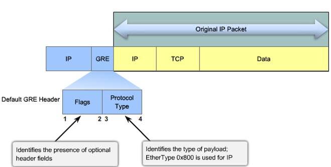
Source: [11]
The GRE tunnels are not encrypted, it is required to statically configure unique IP addresses on all the end points to manually establish the tunnel. Hence, this is not a scalable solution even if there are more than 50 end points due to IP addresses exhaustion and too much of configuration requirement.
As the GRE is encapsulating protocol, it adds the Flag field identifying the presence of optional header and Protocol Type header that identifies the payload type. Hence the maximum transfer unit (MTU) is set to 1400 bytes and maximum segment size (MSS) as 1360 bytes since most of device’s supporting MTUs are less than 1536 bytes. Thus additional GRE headers can be accommodated into the original IP Packet.
By doing so, GRE is greatly useful in sending non IP traffic over the IP network thereby supporting multicast and broadcast traffic over its tunnel. All routing protocols are supported and can be implemented in GRE.
One of the best and simple flowchart found on the below website that could be handy to network architects.
tcpflag.blogspot.in/2011/01/configuring-site-to-site-gre-tunnel.html
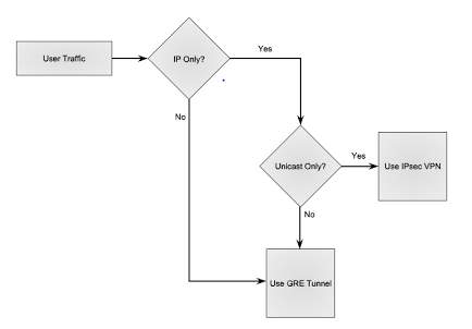
Source: [11]
GRE Implementation
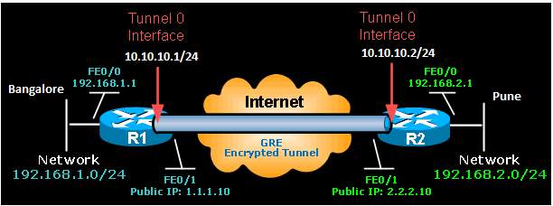
Figure 6. 3: Point to Point GRE
On the Bangalore router:
Bangalore(config)# interface Tunnel0
Bangalore(config)# description GRE Tunnel to Pune
Bangalore(config-if)# ip address 10.10.10.1 255.255.255.0
Bangalore(config-if)# ip mtu 1400
Bangalore(config-if)# ip tcp adjust-mss 1360
Bangalore(config-if)# tunnel source 1.1.1.10
Bangalore(config-if)# tunnel destination 2.2.2.10
On the Pune Router:
Pune(config)# interface Tunnel0
Pune(config)# description GRE Tunnel to Bangalore
Pune(config-if)# ip address 10.10.10.2 255.255.255.0
Pune(config-if)# ip mtu 1400
Pune(config-if)# ip tcp adjust-mss 1360
Pune(config-if)# tunnel source 2.2.2.10
Pune(config-if)# tunnel destination 1.1.1.10
Hence the GRE tunnels are created between Pune and Bangalore.
IPSec over GRE Implementation
IPSec when used along with GRE it provides security as well as flexibility combining the benefits of encryption and encapsulation.
To run IPSec over GRE, We create a new profile named ‘GRE’ with previously defined ISAKMP and IPSEC policies under ‘MYSET’.
Bangalore(config)# crypto ipsec profile GRE
Bangalore(ipsec-profile)# set transform-set MYSET
Pune(config)# crypto ipsec profile GRE
Pune(ipsec-profile)# set transform-set MYSET
Bangalore(config)# interface Tunnel 0
Bangalore(config-if)# tunnel protection ipsec profile GRE
Pune(config)# interface Tunnel 0
Pune(config-if)# tunnel protection ipsec profile GRE
Thus the tunnel can be encrypted using IPSec over the GRE encapsulation.
However, the drawback of IPSec over GRE is it adds the overhead onto the packet thereby adding latency by decreasing the payload size, high bandwidth on the WAN links, higher CPU cycles in order to process these packets by the router.
There are 2 modes of IPSec over GRE like that of IPSec. They are;
IPSec over GRE Tunnel Mode
In the IPSec over GRE Tunnel mode, entire GRE IP packet and the original IP packet is encapsulated, encrypted and protected inside an IPSec packet. Tunnel mode implementation also support Multicasting thus providing a platform to run dynamic routing protocol between sites. Hence it provides the fool-proof security as even IP header is not compromised.
The original IP header of the packet is encrypted and encapsulated with a new IP header that is to be sent.
The size of the IV (Initialization Vector) can vary upon the encryption algorithm that is used. ESP trailer can vary in its size based upon the Pad Length, Next Header information and ESP Trailer fields. Calculating the overhead as per the below figure,
ESP Header: 20 byte IP Header + 8 byte ESP Header + 8 byte Initialization Vector + 4 byte ESP Trailer + 12 byte ESP Authentication Trailer = 52 Bytes Encapsulation Security Payload.
GRE Header: 20 byte GRE IP Header + 4 byte GRE containing protocol type and flags = 24 Bytes GRE overhead.
Total Overhead: ESP Overhead + GRE Overhead = 76 Bytes
To select the Tunnel mode of implementation:
!
crypto ipsec transform-set MYVPN esp-aes esp-sha-hmac
mode tunnel
!

Figure 6. 4: Tunnel Mode IPSec over GRE
Source: firewall.cx/cisco-technical-knowledgebase [10]
IPSec over GRE Transport Mode
In the IPSec over GRE Transport mode, GRE IP Header is placed in front which is not encrypted thereby exposing the same. However, there are restrictions as this type of implementation does not support if NAT (Network Address Translations) or PAT (Port Address Translations) in in between the VPN end points. Hence Transport mode can be better implemented as Client to Site model of VPN.
Likewise to that of Tunnel mode, the size of the IV (Initialization Vector) can vary upon the encryption algorithm that is used. ESP trailer can vary in its size based upon the Pad Length, Next Header information and ESP Trailer fields. Thus calculating the overhead as per the below figure,
ESP Header : 20 byte IP Header + 8 byte ESP Header + 8 byte Initialization Vector + 4 byte ESP Trailer + 12 byte ESP Authentication trailer = 52 Bytes Encapsulation Security Payload Overhead.
GRE Header: 4 byte GRE header containing Flags and Protocol type fields = 4 Bytes GRE Overhead.
Total Overhead: ESP Overhead + GRE Overhead = 56 Bytes.
To select Transport mode of implementation,
!
crypto ipsec transform-set MYVPN esp-aes esp-sha-hmac
mode transport
!

Figure 6. 5: Transport Mode Header IPSec over GRE
Source: firewall.cx/cisco-technical-knowledgebase [10]
Summary
However, it is evident that IPSec over GRE transport mode has lesser overhead compared to that of tunnel mode but has may limitations in implementing the same as pointed out. Although, there are issue with maximum overhead on tunnel mode, it can certainly not be ignored for the fact that it provides the fool-network security.
Chapter – 7
DMVPN – Dynamic Multipoint VPN
Cisco introduce DMVPN (Dynamic Multi Point VPN) to alleviate the problems in GRE. It uses the concept of Multi-point GRE (mGRE) that do not have tunnel destination. This implementation model keeps the running costs low, minimizing the configuration complexity and also increases the flexibility.
Hub and Spoke topology is where one router with high processing power is centrally placed in the Headquarters as Hub and remote branches are deployed with a normal router acting as a Spoke.
DMVPN incorporates 2 major implementation designs namely;
- DMVPN Hub & Spoke Model, used to deploy headquarters-to-branch interconnections where spokes communicate with each other securely through the Hub.
- DMVPN Spoke-to-Spoke Model, used to deploy secure branch-to-branch interconnections.
Static IP is assigned to the routers in Headquarters in both the deployment designs.
DMVPN combines mGRE, IPSec, NHRP (Next Hop Resolution Protocol) and Dynamic Routing protocols such as EIGRP, OSPF, and BGP to dynamically build the VPN tunnel reducing the overhead job for a Network Engineer.
NHRP means Next Hop Resolution protocol. It provides L2 address resolution protocol and caching services like that of ARP (Address Resolution Protocol) and inverse ARP. It maps the tunnel IP with NBMA (Non Broadcast Multi Access) address (Static or Dynamic). NHRP builds dynamic database containing IP addresses of spokes.
- Hub router acts as a server while the spoke router works like a client. NHRP builds the dynamic database stored on the Hub with information about spoke’s public IP Address. Thus the Hub maintains NHRP database of public IP Addresses of spokes to build a dynamic VPN tunnels.
- The Public IP Addresses of each spoke is copied into the Hub router and the spokes queries the NHRP database stored in HUB router for the public IP addresses of the other spokes to build a spoke to spoke dynamic VPN tunnel.
BENEFITS OF DMVPN [10]
DMVPN provides a number of benefits which have helped make them very popular and highly recommended. These include: [10]
Simplified Hub Router Configuration. No more multiple tunnel interfaces for each branch (spoke) VPN. A single mGRE, IPSec profile without any crypto access lists, is all that is required to handle all Spoke routers. No matter how many Spoke routers connect to the Hub, the Hub configuration remains constant. [10]
Full Support for Spoke Routers with Dynamic IP Addressing. Spoke routers can use dynamic public IP Addresses. Thanks to NHRP, Spoke routers rely on the Hub router to find the public IP Address of other Spoke routers and construct a VPN Tunnel with them. [10]
Dynamic Creation of Spoke-to-Spoke VPN Tunnels. Spoke routers are able to dynamically create VPN Tunnels between them as network data needs to travel from one branch to another. [10]
Lower Administration Costs. DMVPN simplifies greatly the WAN network topology, allowing the Administrator to deal with other more time-consuming problems. Once setup, DMVPN continues working around the clock, creating dynamic VPNs as needed and keeping every router updated on the VPN topology. [10]
Optional Strong Security with IPSec. Optionally, IPSecurity can be configured to provide data encryption and confidentiality. IPSec is used to secure the mGRE tunnels by encrypting the tunnel traffic using a variety of available encryption algorithms. [10]
DMVPN OPERATION – HOW DMVPN OPERATES? [10]
DMVPN operation in a network is summarized clearly by following points from the author of [10];
- Each spoke has a permanent IPSec tunnel to the hub but not to the other spokes within the network.
- Each spoke registers as a client of the NHRP server. The Hub router undertakes the role of the NHRP server.
- When a spoke needs to send a packet to a destination (private) subnet on another spoke, it queries the NHRP server for the real (outside) address of the destination (target) spoke.
- After the originating spoke learns the peer address of the target spoke, it can initiate a dynamic IPSec tunnel to the target spoke.
- The spoke-to-spoke tunnel is built over the multipoint GRE (mGRE) interface.
- The spoke-to-spoke links are established on demand whenever there is traffic between the spokes. Thereafter, packets are able to bypass the hub and use the spoke-to-spoke tunnel.
- All data traversing the GRE tunnel is encrypted using IPSecurity (optional)
NHRP: Next Hop Resolution Protocol
- In NHRP (RFC 2332), Routers can be configured as Next Hop Servers (NHS) and Next Hop Clients (NHC).
- NHS maps all the NHCs and replies to the query made by NHCs.
- NHCs send query to NHS if it needs to communicate to another NHC.
NHRP Messages
Registration Request
- NBMA and the tunnel IP each spoke is copied into to NHS.
- Necessary in building hub to spoke tunnels.
Resolution Request
- Spokes query for NBMA and tunnel IP of other spokes.
- In order to build dynamic spoke to spoke tunnels.
Redirect Message
- NHS answers spoke to spoke data plane packet through it.
- Used in DMVPN Phase 3 to build spoke to spoke tunnels.
DMVPN Phases
Phase 1
- Deprecated Design.
- Hub to Spokes are configured mGRE and Spokes to Spokes are configured P2P GRE.
- No Dynamic Spoke to Spoke tunnels.
- All traffic goes through the Hub.
Phase 2
- Both Hubs and Spokes are configured as mGRE.
- Spoke to Spoke tunnels are dynamically created.
- Spoke to spoke resolution is done through NHRP.
Phase 3
- Hub to Spoke and Spoke to Spoke direct communication is made possible.
- Scalability is improved drastically by using NHRP redirects.
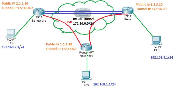
Figure 7. 1: Configuration: Configuring DMVPN Hub “New York”
DMVPN Configuration & Implementation:
Firstly, assigning the IP address for the LAN and WAN network. IP reachability is maintained by Routing Protocols.
interface FastEthernet0/0
description LAN-Network
ip address 192.168.1.1 255.255.255.0
duplex auto
speed auto
!
interface FastEthernet0/1
description WAN-Network
ip address 1.1.1.10 255.255.255.0
duplex auto
speed auto
interface Tunnel0
description mGRE – DMVPN Tunnel
ip address 172.16.0.1 255.255.255.0
no ip redirects
ip nhrp authentication cisco
ip nhrp map multicast dynamic
ip nhrp network-id 1
tunnel source 1.1.1.10
tunnel mode gre multipoint
On Configuring the Tunnel Interface, Tunnel destination is not configured as it is multipoint GRE tunnel.
- ‘map multicast dynamic’ enables forwarding of multicast traffic across the tunnel to dynamic spokes which is usually required for OSPF, EIGRP advertisement messages.
- ‘ip nhrp network-id 1’ identifies the DMVPN cloud, All routers (Spokes or Hubs) participating in this DMVPN should have a same network-id configured to form the end points or tunnels.
- ‘nhrp authentication’ segregates the unwanted NHRP queries out of the DMVPN network.
Now, Configuring DMVPN Spoke ‘Bangalore’
interface FastEthernet0/0
description LAN-Network
ip address 192.168.2.1 255.255.255.0
duplex auto
speed auto
!
interface FastEthernet0/1
description WAN-Network
ip address 2.2.2.10 255.255.255.0
duplex auto
speed auto
Configured LAN and WAN network, now configuring Tunnel Interface on Bangalore Router.
interface Tunnel0
description R2 mGRE – DMVPN Tunnel
ip address 172.16.0.2 255.255.255.0
no ip redirects
ip nhrp authentication firewall
ip nhrp map multicast dynamic
ip nhrp map 172.16.0.1 1.1.1.10
ip nhrp map multicast 1.1.1.10
ip nhrp network-id 1
ip nhrp nhs 172.16.0.1
tunnel source FastEthernet0/1
tunnel mode gre multipoint
On ‘Pune’ Router, configuring LAN and WAN interface,
interface FastEthernet0/0
description LAN-Network
ip address 192.168.3.1 255.255.255.0
duplex auto
speed auto
!
interface FastEthernet0/1
description WAN-Network
ip address 3.3.3.10 255.255.255.0
duplex auto
speed auto
Configuring Tunnel Interface on Pune Router.
interface Tunnel0
description R3 mGRE – DMVPN Tunnel
ip address 172.16.0.3 255.255.255.0
no ip redirects
ip nhrp authentication firewall
ip nhrp map multicast dynamic
ip nhrp map 172.16.0.1 1.1.1.10
ip nhrp map multicast 1.1.1.10
ip nhrp network-id 1
ip nhrp nhs 172.16.0.1
tunnel source FastEthernet0/1
tunnel mode gre multipoint
Output:
R1# show dmvpn
Legend: Attrb –> S – Static, D – Dynamic, I – Incomplete
N – NATed, L – Local, X – No Socket
# ENT –> Number of NHRP entries with same NBMA peer
NHS Status: E –> Expecting Replies, R –> Responding
UpDn Time –> Up or Down Time for a Tunnel
==========================================================================
Interface: Tunnel0, IPv4 NHRP Details
Type: Hub, NHRP Peers: 2,
Ent Peer NBMA Addr Peer Tunnel Add State UpDn Tm Attrb
—– ———————- ————— —– ——– —–
1 2.2.2.10 172.16.0.2 UP 00:04:58 D
1 3.3.3.10 172.16.0.3 UP 00:04:12
These GRE Tunnels can further be secured by encrypting with IPSec profile ‘GRE’ implemented in the previous section. Implemented both on the hub as well as spokes.
New_York(config)# interface tunnel 0
New_York(config-if)# tunnel protection ipsec profile GRE
Bangalore(config)# interface tunnel 0
Bangalore(config-if)# tunnel protection ipsec profile GRE
Pune(config)# interface tunnel 0
Pune(config-if)# tunnel protection ipsec profile GRE
DMVPN: Summary
The revolutionary VPN architecture design providing flexibility, scalability, stability, low administrative overhead, ease of administration makes it the VPN solution in today’s ever-growing IT infrastructure. With the point to point GRE with IPSec Encryption Spoke to spoke traffic had to pass through the HUB. But, in case of DMVPN, spoke to spoke traffic can communicate directly. No need for any changes in the HUB during the addition of Spokes unlike the point to point GRE with IPSec VPN. One mGRE tunnel can connect to multiple end points creating multiple instances of DMVPN.
Chapter – 8
Summary
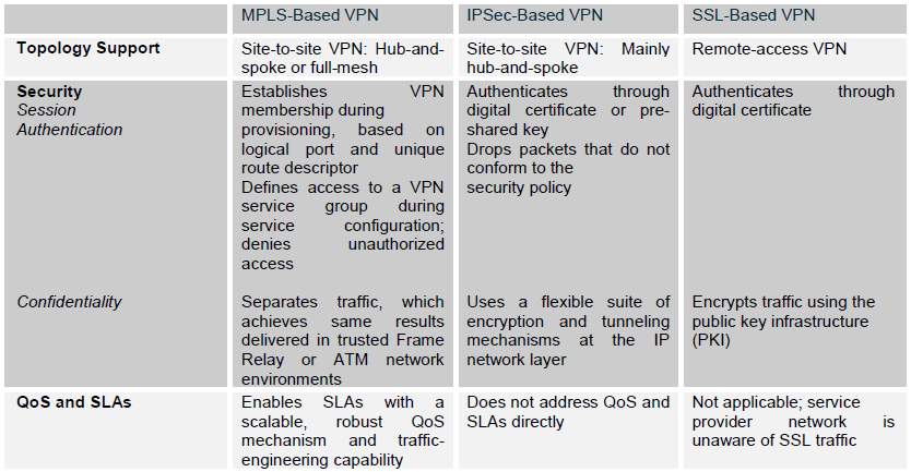
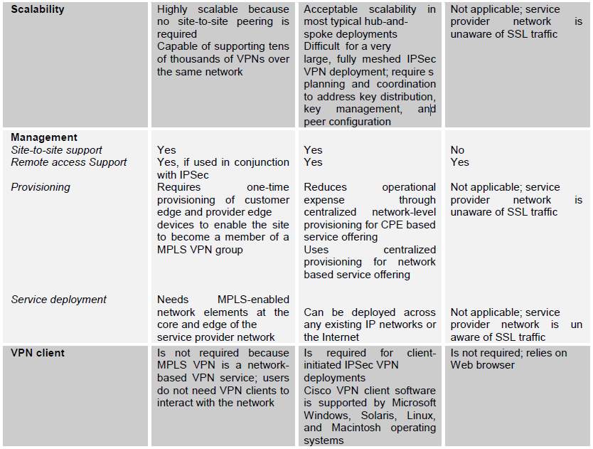
VPN Architecture Comparison Table [9]

Chapter – 9
Redundancy and High Availability using HSRP
High availability is critical in almost all the networking infrastructure. To attain device high availability and real time failover, Cisco developed their proprietary protocol named as HSRP (Hot Standby Routing Protocol).
The failover redundancy mechanism is achieved having two separate routers acting as a single virtual gateway and MAC address.
HSRP exchanges ‘Hello’ messages to form HSRP group. If multiple HSRP is running on the Router, the unique HSRP group number needs to be identified to run the desired HSRP instance. The role of an HSRP router is dictated by its priority. The ‘Higher’ priority is preferred as a gateway.
HSRP States
HSRP propagates from the following states in the following order during the event of changes in HSRP.
Disabled: When the router interface is administratively shutdown.
Initial: Interface entering the learning state.
Learn: Learns the virtual IP address.
Speak: Router participating in the election of Active and Standby role.
HSRP Roles
- Active Router: Router running as a Gateway.
- Standby Router: Backup to the Active Router.
- Listening Router: All other routers participating in their HSRP instances.
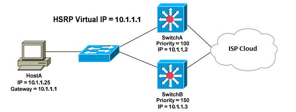
Figure 9. 1: HSRP Configuration Setup
Configuration
On Switch A:
SwitchA(config)# interface vlan 100
SwitchA(config-if)# ip address 10.1.1.2 255.255.255.0
SwitchA(config-if)# standby 1 authentication md5 key-string 7 CISCO
SwitchA(config-if)# standby 1 ip 10.1.1.1
SwitchA(config-if)# standby 1 priority 110
SwitchA(config-if)# standby 1 track <exit interface> 60
SwitchA(config-if)# standby 1 preempt
On Switch B:
SwitchB(config)# interface vlan 100
SwitchB(config-if)# ip address 10.1.1.3 255.255.255.0
SwitchB(config-if)# standby 1 ip 10.1.1.1 Virtual IP
SwitchB(config-if)# standby 1 priority 150 Highest priority preferred as Gateway.
To specify an MD5-hashed authentication string:
SwitchB(config-if)# standby 1 authentication md5 key-string 7 CISCO
The priority of the switch will decrease by 60. The objective is to decrement the priority enough to allow the standby router to take over as active.
SwitchB(config-if)# standby 1 track <exit interface> 60
SwitchB(config-if)# standby 1 preempt
Chapter – 10
Policy Based Routing
Chapter – 11
Network Design
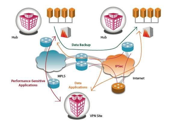
Figure 11. 1: Hybrid VPN Design -1
Source: TATA’s Hybrid VPN, White paper
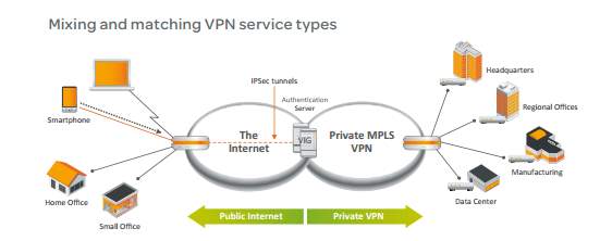
Figure 11. 2: Hybrid VPN Design -2
Source: AT&T’s Hybrid VPN, White paper
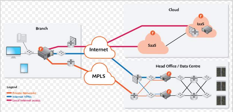
Comparing the above Hybrid VPN designs by the two very famous service providers, we understand that the Organization’s main Headquarters and their Disaster Recovery is often connected over the ISP guaranteed MPLS VPN separated by VRF at the provider’s edge as we have studied earlier.
The remote branches are connected as phase 3 model of Dynamic Multi Point VPN with IPSec encrypted security between Hub and Spoke’s mGRE. Thus it provides fool proof security across the public internet.
The Redundancy and Failover of the network devices across all the Branches are configured with HSRP as studies earlier.
Having two links to the service provider network, the traffic is load balanced across both the links prioritizing the Intranet traffic across the Hub on dedicated connection and Internet traffic browsed locally out of the firewall in the remote site.
High Level WAN Diagram:
Hub locations are interconnected by MPLS VPN which offers advanced QoS and Traffic Engineering.
Remote Branches are connected as spokes to the Hubs on the DMVPN setup. The remote branches are connected as phase 3 model of Dynamic Multi Point VPN with IPSec encrypted security between Hub and Spoke’s mGRE. Thus it provides fool proof security across the public internet.
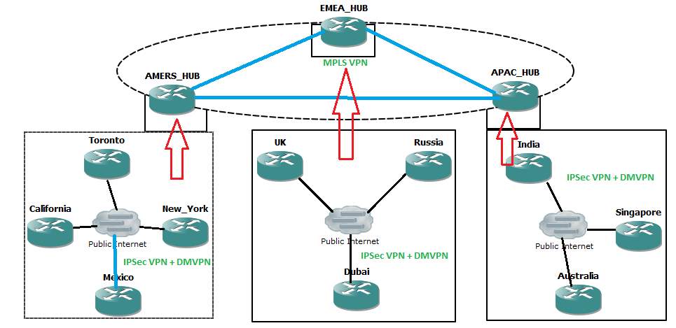
Figure 11. 3: High-level Design – Hubs
Redundancy in HUB location:
Low Level Diagram : At the Hub
In the below diagram, The Hub location is further bifurcated into the redundant paths. While Hub-1 connected over to provider edge through ABC Service provider and Hub-2 is connected over to provider edge of XYZ Service provider thereby having the redundancy and failover capabilities and is implemented based on the HSRP explained earlier.
Low Level Diagram: At the Hub
Spoke to Spoke redundancy is also achieved by the below network design where connectivity to Hub-1 and Hub-2 provides hardware level redundancy over the same service provider’s MPLS VPN. The implementation is achieved using the concept of PBR (policy based routing) and HSRP for the redundancy at the DMVPN Spokes as explained in earlier section.
The same model is replicated across EMEA as well as APAC networks.
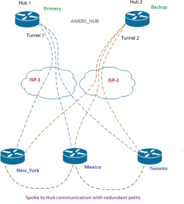
Figure 11. 4: Low Level Diagram – Hub
Low Level Diagram: At the Spoke
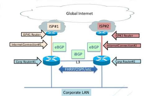
Figure 11. 6: Low-level diagram at spokes
Policy based routing are applied at the router 1 and router 2 of the spoke, the routes are redistributed to into the IGP. Internet traffic is dedicated to a different gateway. Caution is exercised to be high available and fail over dynamically propagating all the traffic over to the redundant path. In case of one of the ISP fails, HSRP will take care of dynamically moving the traffic to redundant path and PBRs will take care of congestion control in a bottleneck link as explained in PBR concepts earlier.
Glossary
| Term | Definition |
| BGP | Border Gateway Protocol |
| eBGP | External Border Gateway Protocol |
| iBGP | Internal Border Gateway Protocol |
| MP-BGP | Multi-Protocol Border Gateway Protocol |
| MAN | Metropolitan Area Network |
| MPLS | Gateway Load Balancing Protocol |
| HSRP | Hot Standby Routing Protocol |
| IME | Internal Messaging Environment |
| IPSec | Internet Protocol Security |
| QoS | Quality of Service |
| L2, L3 | Layer2, Layer 3 |
| OSPF | Open Shortest Path First |
| GRE | Generic Routing and Encapsulation |
| SNMP | Simple Network Management Protocol |
| STP | Spanning-Tree Protocol |
| MPLS | Multi-Protocol Label Switching |
| LDP | Label Distribution Protocol |
| VLAN | Virtual Local Area Network |
| VPN | Virtual Private Network |
| VRF | VPN Routing and Forwarding Instance |
| VRRP | Virtual Router Redundancy Protocol |
| WAN | Wide Area Network |
| PBR | Policy Based Routing |
| CE | Customer Edge (router) |
| RIB | Routing Information Base |
| mGRE | Multipoint GRE |
| NTP | Network Time Protocol |
| DMVPN | Dynamic Multipoint Virtual Private Network |
| FIB | Forward Information Base |
| NHRP | Next Hop Resolution Protocol |
Chapter – 12
Future Scope & Conclusion
VPN is an emerging technology which is in great demand in dynamic IT industries. From an insecure public internet to a powerful business network that uses the Internet as its gateway. VPN technology is dynamically developing to meet the ever-growing business needs such as security, scalability and ease of administration. With VPN, businesses now have alternative benefits to offer to their employees, where employees can work from home while still being productive and have access to work at any time. This greatly reduces the business operation costs where a company need not provide a conveyance, office space, electric power to their employees. VPN thus help start-ups and several small scale businesses to grow and expand geographically creating a virtual office setup across the international boundaries capturing talent in this emerging world of IT. MPLS VPNs have fundamental traffic engineering and QoS capabilities to support optimal performance. IPsec traffic will traverse the MPLS VPN for a double layer of security.
Hybrid VPNs are the future network services. If properly implemented, they can simplify network operations while reducing huge capital expenditures. For most organizations, the inception is to connect widely separated workgroups in highly efficient manner. Service providers can influence the main technology as a foundation for offering additional services such as application hosting, videoconferencing or other emerging cloud services.
References
- Inter-AS Hybrid for MPLS VPN over IP Tunnels – Cisco Systems, http://www.cisco.com/c/en/us/td/docs/ios/12_0s/feature/guide/hybrd10b.html
- Dayananda M S, Ashwin Kumar, “Architecture for inter-cloud services using IPsec VPN”, © 2012 IEEE.
- Fahad A. Arshad, gaspar modelo-howard, saurabh bagchi “to cloud or not to cloud: A study of trade-offs between in-house and outsourced virtual private network”, © 2012 IEEE.
- Siddeeq Y. Ameen, Shayma Wail Nourildean , “Firewall and VPN Investigation on Cloud Computing Performance” , IJCSES, April 2014.
- Su Hua Sun, “The advantages and the implementation of SSL VPN”, ©2011 IEEE.
- Ferguson, Paul, and Geoff Huston. “What is a VPN” (1998).
- Bacon, Germaine, et al. “Virtual Private Network.” (1998).
- Jazib Frahim, Qiang Huan, “SSL Remote Access VPN”, Cisco Press, June 2008, ISBN: 978-1-58705-242-2, 1-58705-242-3
- Cisco Systems, “Managed VPN – Comparison of MPLS, IPSec, and SSL Architectures”, White paper, Cisco Systems.
- Firewall.cx, http://www.firewall.cx/cisco-technical-knowledgebase/cisco-routers/
- tcpflag.blogspot.in/2011/01/configuring-site-to-site-gre-tunnel.html
- Vivek Alwyn “Advanced MPLS Design and Implementation”, Cisco Press, Sep 25, 2001, ISBN-10: 1-58705-020-X; ISBN-13: 978-1-58705-020-6.
Checklist of items for the Final Dissertation Report
This checklist is to be duly completed, verified and signed by the student.
|
|
Is the final report neatly formatted with all the elements required for a technical Report? | Yes |
|
|
Is the Cover page in proper format as given in Annexure A? | Yes |
|
|
Is the Title page (Inner cover page) in proper format? | Yes |
|
|
(a) Is the Certificate from the Supervisor in proper format?
(b) Has it been signed by the Supervisor? |
Yes
Yes |
|
|
Is the Abstract included in the report properly written within one page? Have the technical keywords been specified properly? | Yes
Yes |
|
|
Is the title of your report appropriate? The title should be adequately descriptive, precise and must reflect scope of the actual work done. Uncommon abbreviations / Acronyms should not be used in the title | Yes |
|
|
Have you included the List of abbreviations / Acronyms? | Yes |
|
|
Does the Report contain a summary of the literature survey? | Yes |
|
|
Does the Table of Contents include page numbers?
|
Yes
Yes Yes Yes Yes Yes |
|
|
Is the conclusion of the Report based on discussion of the work? | Yes |
|
|
Are References or Bibliography given at the end of the Report?
Have the References been cited properly inside the text of the Report? Are all the references cited in the body of the report |
Yes
Yes Yes |
|
|
Is the report format and content according to the guidelines? The report should not be a mere printout of a Power Point Presentation, or a user manual. Source code of software need not be included in the report. | Yes |
Declaration by Student
I certify that I have properly verified all the items in the checklist and ensure that the report is in proper format as specified in the course handout.

Signature: ———————-
Place: Pune
Date: 31-03-2017
Name: Alok Hiriyur
ID No: 2014HT13511
Cite This Work
To export a reference to this article please select a referencing stye below:
Related Services
View allRelated Content
All TagsContent relating to: "Computer Science"
Computer science is the study of computer systems, computing technologies, data, data structures and algorithms. Computer science provides essential skills and knowledge for a wide range of computing and computer-related professions.
Related Articles
DMCA / Removal Request
If you are the original writer of this dissertation and no longer wish to have your work published on the UKDiss.com website then please:


