Vulnerabilities and Threats for IoT and Security Mechanisms Available
Info: 11501 words (46 pages) Dissertation
Published: 16th Dec 2019
Tagged: Cyber SecurityInternet of Things
IoT/WSN Security
Table of Contents
Introduction and Report Outline
2.4 IOT in WSN and its security
2.5 Study of WSN suitable simulators:
2.5.1 Study of Suitable Hardware platform:
2.5.2 Study of Arduino Platform, Wi-Fi Shield and sensors.
2.5.4 Technical Specifications:
2.5.6 Temperature Sensor: LM35
3.1.7 Other Risks and Vulnerability analyzed in Wireless sensor:
Formation of Physical and Virtual nodes
Interfacing Arduino Data with Simulator Securely
7.1 Security to the Data transferred
8.5 Security Challenges in WSN:
8.5.7 Denial of Service (dos):
8.6.3 Components explanation in AES:
CHAPTER 1
Introduction and Report Outline
1.1 Aims and Objectives:
As we all aware of the current market trend toward IoT and its applications swelling day-by day, security is one important parameter to be considered for the IoT applications for assuring privacy of data stored, transmitted or received through internet to end points protecting from hackers.
As we move towards more sophisticated world, where our machines communicate with another machine to get the job done for us, the key element here are sensors and cloud data. The sensor is the element which collects the data, processes it and sends the information to the cloud for leveraging. This data is sent to the user end points which are taking our life in a much smarter, advanced and automated way. It is to be said that Internet of things does not make any value without sensors and cloud network. But the very big question rising in our minds is, is the data transferred or received is secured and unaltered?
One of the most common and reliable network of IoT in today’s world is through WSN (Wireless sensor networks). WSN is a network of small electronic devices or nodes which consist of different sensors. The prime purpose of Wireless sensor is to collect the data and pass it to base station or edge node securely in its network. This data is then passed to the internet to reach the end user points.
This project aims in exploring the vulnerabilities and threats available to IoT (Internet of things) and thereby analyzing the security mechanism available for the IoT devices used in any specific application. Once getting a clear information about the vulnerabilities, threats and security mechanisms for an IoT, security mechanism over simulation tool will be applied to any one IoT application networks (WAN,WSN,LAN).Preferably choosing WSN as it is the most used application in Industries and corporate. Adding to the simulation part, a real sensor node will be selected and then its sensed data will be fed to the simulator securely. Finally, the communication and performance from real node and virtual node in the simulator will be seen in the analytics.
1.2 Literature Survey:
- A detailed analysis on IoT,WSN along with IOT facts related to its process and security factors has been discussed.
- Study of WSN suitable simulators. (Simulator which supports combination of physical come virtual devices).
- Study of Arduino microcontroller platform which receives the input from sensor nodes and processes the output.
- Study of Wi-Fi shield, which helps to connect to the internet wirelessly through Arduino
- Study and selection of sensor nodes (Temperature sensor nodes)
- Formation of nodes in Simulator with base station node
- Interfacing of physical node data to Simulator
- Applying Security to nodes communication to base station.
Theory: A brief details about the analytical work carried on for this project.
High Level Architecture: A detailed diagram about the IoT system and explanation about the overall process.
Requirements: Discussion of software and hardware requirements and way to do it.
Implementation: Implementation of the project phase by phase
Reference: A detailed reference for all the inputs gathered in the report.
CHAPTER 3
THEORY
3.1 Analytical work:
As IoT is comprised of multiple components like protocols, hardware and software, security is a major challenge in it and due to this there are a lot of vulnerabilities found in IoT components are discussed in detail in the below document.
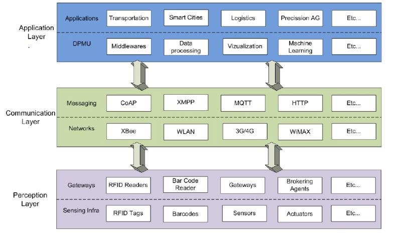
To start with IoT layers to know what each layer is responsible and role of each layer, we shall look at the below diagram for our understanding.
 [9]
[9]
Layer description and vulnerabilities found in each layer of IoT
The role of the physical layer in any device is to transmit and receive the raw data over a physical medium. The medium can be electrical, mechanical or functional interfaces. Ultimately it carries the signal to the upper layers. For IoT applications, physical layers should have considered with the following functionalities. They are modulation, data rate, transmission mode and channel encoding, frequency generation and signal detection[16]
The most famous attacks in physical layer especially in WSN environment is jamming and tampering. Jamming is one such DOS attacks which will affect the network by sending a high broadcast signal. Tampering is more related to physical attacks where the user can extract the key security information from the node, alter it and replace it. [17]
The data link layer is responsible for error-free data and this is the layer which has a hardware address for the sensor. The actual topology for the hardware connections is defined in this layer. This layer supports both connection and connectionless services. The common protocols implemented in physical and data link layers in IoT are Ethernet,3g,4g, GSM, WiFi etc. [18]
The threats in this layer are continuous channel access where a malicious node disturbs the MAC by continuously sending signals over the channel which will make other nodes to starve. The other attack in this layer is collision attack where two nodes transmit the information at the same frequency which will ultimately cause checksum mismatch error. [19]
This is the layer where the routing protocols for the local network are configured. The unique IP of each device is defined in this layer and way for communication to other networks is configured here. Some of the WSN routing protocols are GEAR, LEACH, TEEN (APTEEN) and SPIN. These routing protocols help the individual node to process the data to next nearby node and to find the best route to reach the destination.
The network layer is more susceptible to many attacks such as spoofed routing information, sinkhole, hello flood and acknowledgment spoofing etc. Among this spoofed routing information is the most common attack as the target attack is on the routing information exchanged between the sensor nodes. Through this attack, hackers can cause network traffic, generate fake messages and cause a delay in latency. [19]
An important consideration in IoT is security layer. This is the layer where security mechanism is designed over the routing protocols and acts as a savior for the data collected and transferred to the gateway. Implementation of security algorithms has thoroughly analyzed before execution as most of the IoT devices have the low processing power and memory storage due to which all security algorithms cannot be implemented as they require large storage and processing power which nodes cannot provide. Security administrators should know the type of application and dependency of security on it to implement the best available security mechanism. The key here is to compromise some features of security algorithms and node features to get the better performance and efficiency. Security algorithms depend upon technologies being used. Some of the security mechanisms based on different technologies are as follows.
| Communication Protocols | Security mechanism |
| WIFI | WEP, AES,TKIP, 802.1x,WPA and WPA2 |
| Zigbee | Link Layer Encryption using AES 128, TLS, EAP |
| 6LowPAN | Access Control List , 802.15.4 link layer encryption |
| Bluetooth | Secure pairing |
[9]
The most vulnerable layer in WSN is transport layer as it is prone to an enormous number of attacks like flooding, de-synchronization, energy drain attacks, black hole attacks, node replication attacks and homing. Among them, flooding and de-synchronization a most common attack. Flooding is where the attacker gives request repeatedly where at one point the connection is exhausted or would have reached its maximum limit. Ultimately this will drain the Cpu resource which will result in the low performance of the sensor node.
This is the most important layer in IoT where various applications can use IoT for service enhancement. Applications can be categorized based on various parameters like type of network, business model, and size and network coverage. The scalability differs based on the type of application it is involved. E.g ,for home based applications the available number of users will be less so the scalability here is either medium or small, whereas scalability in the enterprise is large as a lot of applications rely on IoT in enterprise level. [20]
3.1.7 Other Risks and Vulnerability analyzed in Wireless sensor:
Some of the possible attacks on sensor networks in wireless mode are, a hacker can eavesdrop on the communication sent from one node to another or to gateway. Apart from this traffic analysis can be done, replay attacks, false injection of messages can be done, denial of service attacks which is jamming off the channel with multiple packets creates congestion in the networks. Ultimately all these attacks drain sensor battery which will result in a performance drop. [21]
Some other attacks performed on IoT device especially on sensors are gaining access to the internal state of the node through injecting some software bugs on the sensor nodes or in the base station. Physical attacks are the next dangerous risk in IoT devices. They can be in any form ranging from medium to very large. Some of them are as follows
- Replacement of sensors and chipsets
- Simulating Electrically Erasable Programmable read only memory
- Changing the programed interface at the controller level.
- Brute force password guessing
- Other Invasive attacks [21]
Overall in IoT layers,Vulnerabilities are found in perception layer (sensor and gateways) Communication layer (networks and messaging) and finally application layer (application and service unit).
3.1.8 Perception layer:
Sensors, gateways, RFID, M2M terminals are the major components of this layer.These components involved here have the low processing power and memory so a minimum level of security configurations are applied here with respect to the performance of the nodes. They possess multiple security vulnerabilities such as Integrity, confidentiality, authentication, denial of service attack, forwarding attack, sybil attack, eaves dropping attack, sniffing attack, wormhole attack and acknowledgment spoofing attack. [9]
3.1.9 Communication layer:
This layer is the key layer which utilizes wireless, network infrastructure and data transport mechanism. IoT network and wireless infrastructures are prone to passive and active attacks. Active attacks are DoS (Denial -of-Service), IP spoofing, man in the middle attack Wireless signal jamming, frame injection, flooding and collision attack and de-synchronized attacks. Passive attacks include packet sniffing using sniffer tools. [9]
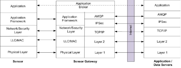
This layer translates the protocol used in sensor networks to Ip family protocols which is suited to internet applications. This is achieved with the help of messaging protocols like HTTP, CoAP, MQTT, AMQP etc. Again these protocols are vulnerable to IP spoofing, port scanning, denial of service, Ip fragmentation and connection high jacking. [9]
 [9]
[9]
3.2 High Level Architecture

3.2.1 Description of High- level architecture:
The above diagram shows the conceptual view of the IoT/WSN hybrid model set up where there is an interfacing of the real sensor node and virtual nodes in the simulator through HIL interface. A physical sensor is selected which can sense any data like temperature, pressure, humidity etc. The sensor is battery powered or can be supported by an external power supply as shown in the diagram.
The sensed data is passed to the simulator through a microcontroller, which processes the data as programmed and this hardware platform is selected to be as Arduino which is an electronic open source platform. The hardware platform can receive the input from sensor and process it to suitable output as expected for the application. The processed output is sent to the simulator through an HIL interface.
The HIL is the technique used to test and run the testbeds output in the simulator which will ultimately save the cost and deployment efforts. As the simulator (Omnet++) is having the capability of accepting a combination of physical sensor nodes and virtual nodes through INET framework, we are forming a set of virtual nodes in the simulator environment. Once the set of virtual nodes is formed, a security mechanism is implemented over the routing protocol used for the communication between the nodes to the base station.
Similarly, security is configured for the physical sensor data as well which is communicating to the simulator. Overall the performance of the physical sensor and virtual sensor nodes is seen in some analytics which will be helpful to determine the efficiency of hybrid implementation. Security in both real node and virtual node communication will be achieved at the end of complete setup.
CHAPTER 4
Software Requirements
4.1 OMNET++
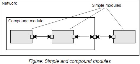
OMNeT++ is an object-oriented discrete event network simulator which has a general architecture. Due to this, it can be used in various platforms. One of the best things about OMNeT++ is it provides infrastructure and tools for writing simulations. Its infrastructure is component architecture for simulation models. Models are assembled for reusable components known as modules. [22]
Here each module can be connected to other modules through gates. Modules communicate through message passing. These modules can pass messages via either gates, connections or directly to their destinations. Connections to direct destinations are mostly used in wireless applications. Each module may have a separate parameter that shows their behavior. The module at the lowest level is called simple module and they encapsulate from here. Simple modules as a group are called as compound modules. The programming language used for programming modules behavior or adding parameters is through C++.
[22]
Some of the applications or uses of OMNeT++ are as follows
- Communication and wired and wireless networks
- Protocol Modelling
- Simulation of hardware models to software
Overall, modelling and simulation of any system where the discrete event simulators is suitable and convenient to map entities communication by exchanging messages. [22]
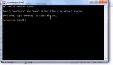
4.1.1 Installing Omnet++
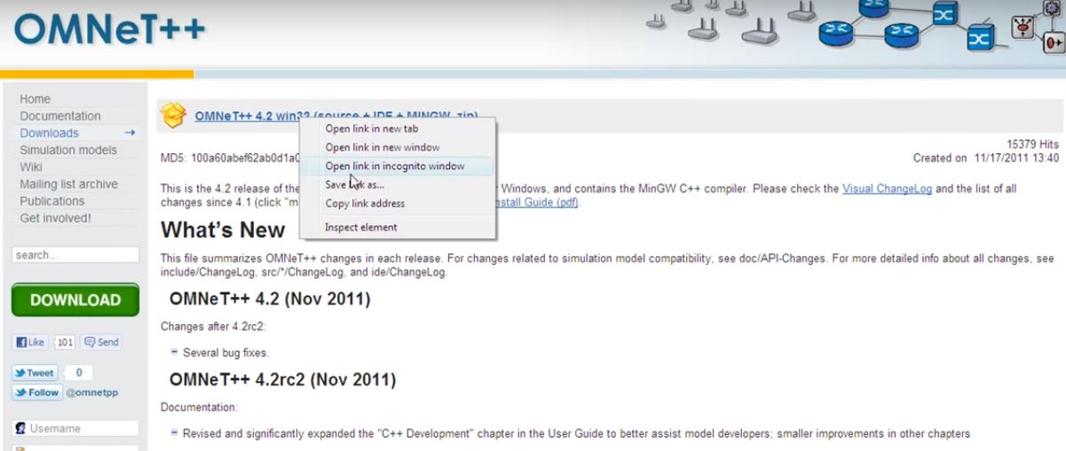
Download the package and install the Omnet++ software in System. Steps are as Follows.
[22]
Once the software is placed in the location to be installed, double-click the Mingwenv.cmd which will prompt for an MSYS bash shell. The Installation will take some time.
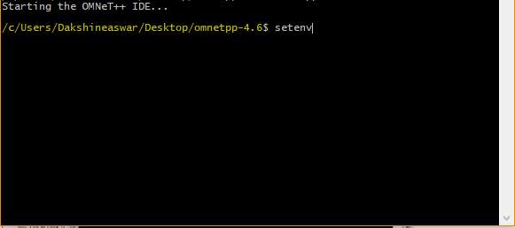
Once successful Installation, type “.setenev” which will set the environment variables
- $ .setenv
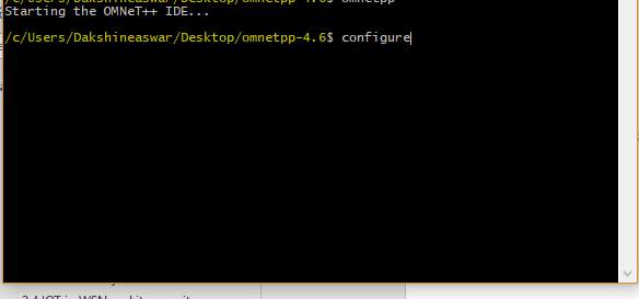
Followed by this type, configure the system by typing following commands
- $ ./configure
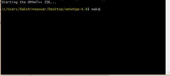
Finally,compile and run the make file by typing the following command.
- $ make
[23]
For adding the environment variables, in the environment variables section, select path and add append, now provide the bin directory path of Omnet++ without any space.
- For example: C:/Omnet-4.6
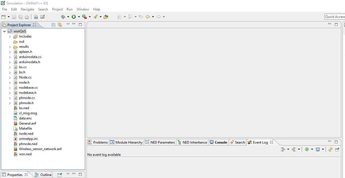
Finally start the Omnet++ IDE by typing
- $ Omnetpp
[22]
Configuration and Building of Omnet++
- $ ./configure
Before configuration, checks the user file to make sure that it contains all the settings we need.Then type the following commands
- $ make
[23]
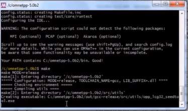
Verifying the Installation, you can now verify that the sample simulations run correctly.
Once done, you should be able to see the GUI. [23]
CHAPTER 5
Formation of Physical and Virtual nodes
Once setting up the simulator, initializing the nodes is next progress. Node creation is done with some of the parameters like energy, distance, temperature slot, node ID. First and foremost, the base station node is created as base station node is the manager of all nodes. Also, all nodes creation is done with gates in and out which is required for communication flow between nodes and among nodes. Once base station node is created, the formation of other virtual nodes can be done with the same parameters but with different values. The speed of the node’s communication is set at a fixed level and it is 40 mps. The setup of nodes is done in 2 dimensions in the format of x and y. Both these dimensions are associated with distance which is necessary for the nodes communication flow. The below shown code is for the creation of base station with the respective parameters.
Being a parent node, the base station has some extra capabilities than the normal nodes. It includes the capacity to count the number of nodes, their distance, nodes status, energy, ability to handle the message and respond to it. [24]
network WSN
{
parameters:
int numNodes;
double trRange;
int rounds;
int frames;
double xMax;
double yMax;
@display(“bgb=2000,2000,white”);
submodules:
bs: BS
{
parameters:
id = 1;
xpos = 1;
ypos = 1;
@display(“p=298,102;is=l;i=device/antennatower”);
}
node[numNodes]: Node
{
parameters:
energy = intuniform(499900, 500000);
id = index+2;
xpos = intuniform(0, xMax);
ypos = intuniform(0, yMax);
@display(“i=device/palm2;t=Sensor Node”);
}
connections allowunconnected:
}
The extra capability configured for the base station nodes is shown below.
void BS::initialize()
{
int i;
cModule* parent = getParentModule();
this->myId = par(“id”);
this->xpos = par(“xpos“);
this->ypos = par(“ypos“);
this->nrNodes = parent->par(“numNodes”);
this->nrGates = parent->par(“numNodes”);
this->nrRounds = parent->par(“rounds”);
this->deadNodes = 0;
this->roundsDone = 0;
this->oldDeadNodes = 0;
this->nrStatusRec = 0;
this->halfDeadCtr = 0;
this->halfDead = 0;
this->calledEnd = 0;
this->roundEnergyLoss = 80001.0;
for (i = 0; i < 104; i++)
{
advInfo[i].id = 0;
advInfo[i].energy = 0;
advInfo[i].status = 0;
}
this->setGateSize(“out”, nrGates + 1);
this->setGateSize(“in”, nrGates + 1);
cMessage* cmsg = new cMessage(“init“);
cmsg->setKind(SMSG_INIT);
scheduleAt(simTime(), cmsg);
}
void BS::initNodes()
{
cModule* parent = getParentModule();
cModule* mod;
int numNodes;
int trRange;
int i;
numNodes = parent->par(“numNodes”);
ev << “BS numNodes is: ” << numNodes << “ ”;
trRange = parent->par(“trRange”);
ev << “BS trRange is: ” << trRange << “ ”;
for(i=1;i<=simulation.getLastModuleId();i++)
{
mod=simulation.getModule(i);
if(strcmp(mod->getName(),”node”)==0)
{
nodePtr[((Node*)mod)->myId]=(Node*)mod;
}
}
}
void BS::handleMessage(cMessage* msg)
{
if (msg->isSelfMessage())
{
ev << “BS: got self message type ” << msg->getKind() << “ ”;
if (msg->getKind() == SMSG_INIT) {
ev << “BS: got start message ”;
this->initNodes();
}
}
else
{
if (((ClusterMessage*) msg)->getProto() == CL_TOBS)
{
ev << “status message ” << “ ”;
double energy;
int cluster;
int status;
int sender;
int clHead;
double curHEnergy;
int curHStatus;
double rating;
double xpos, ypos;
sender = ((Status2BSMessage*) msg)->getSrcAddress();
energy = ((Status2BSMessage*) msg)->getEnergy();
cluster = ((Status2BSMessage*) msg)->getCluster();
status = ((Status2BSMessage*) msg)->getStatus();
xpos = ((Status2BSMessage*) msg)->getXpos();
ypos = ((Status2BSMessage*) msg)->getYpos();
}
} [24]
The temperature set for virtual nodes is constant, set to 36 degrees Celsius and 40 plus virtual nodes are formed with all the parameters mentioned above, which decides the behavior of the node’s temperature for physical nodes is read through the slot created in the node.cc file and this temperature are processed in encryption and decryption (AES 256 bit) along with the virtual nodes temperature. The below shown code is the formation of nodes with the defined parameters.
simple Node
{
parameters:
int id;
double energy;
double xpos;
double ypos;
int temp=default(36);
@display(“p=$xpos,$ypos;i=device/pocketpc”);
double speed @unit(“mps”) = default(10mps); // denotes the speed
double startX @unit(“m”) = default(0m);
double startY @unit(“m”) = default(0m);
double txRange @unit(“m”) = default(200m);
gates:
input in[];
output out[];
}
Next important parameter among nodes is message. Messages are categorized into different forms like status messages, cluster messages, TDMA messages and data to base station messages. Status messages are nothing but letting know the status of the self-node to other nodes and base station with their energy level and the distance between the source and destination nodes.
Cluster messages will be in act when we apply the routing protocol which is required for the communication between and among nodes. The routing protocol used here is APTEEN (adaptive periodic threshold sensitive energy efficient sensor network protocol). Basically, cluster messages consist of the node status, energy level and their distance from the communicating node. Cluster messages will be sent by all nodes to base station so that base station will be able to choose the cluster head.
TDMA messages are meant for transmission time for each node to avoid data collision. In any sensor network, close-by nodes fall in the same cluster which sense similar data and sending the same leads to collision. There is a special parameter in this TDMA messages and it has been named as frames. For each transmission of data, time frames are noted and acknowledged. All these messages will be active once the simulation is started and a suitable routing protocol is applied over the nodes. TDMA message will be broadcasted every 30 seconds as per the set up and the rest of other messages will be in flow among and between nodes.
TDMA messages are meant for transmission time for each node to avoid data collision. In any sensor network, close-by nodes fall in the same cluster which sense similar data and sending the same leads to collision. There is a special parameter in this TDMA messages and it has been named as frames. For each transmission of data, time frames are noted and acknowledged. All these messages will be active once the simulation is started and a suitable routing protocol is applied over the nodes. TDMA message will be broadcasted every 30 seconds as per the set up and the rest of other messages will be in flow among and between nodes.
CHAPTER 6
Routing Protocol
The selected protocol for data transfer is APTEEN in the project. As we all know that application of WSN is huge and has a variety of different scenarios, selecting a routing protocol for communication among and between nodes is very much important. In most applications, there will be more number of nodes where each node is not directly connected. Here routing protocols comes to the rescue by discovering and maintaining the routes in the network. The main task of a sensor node deployed is to collect data from respective domain and process the same to the base station. However because of the slow processing characteristic of the WSN sensor node direct communication from a distant node to base station is not a good idea and so the data are processed by the intermediate nodes so that multiple hops to the base station is established. [25]
In the sensor network model, we have allotted homogenous energy to all nodes and base station have extra power to transmit to the other nodes about their status and role. However other nodes ,once the simulation starts cannot have the same energy as the processing power is very low due to the limited power. Cluster nodes have little bit extra energy than the normal nodes as they must accumulate the data to be sent to the base station. The major advantages of this model are as follows. [26]
- All the nodes need to transmit only to their immediate cluster head.
- The cluster head needs to perform additional processing such as data aggregation etc,
- The routing complexity is reduced as only the cluster head knows the route to the base station.
Once the cluster head is selected in APTEEN, cluster nodes broadcast the needed parameters such as TDMA, schedule, Attributes and thresholds
Attributes: Set of physical parameters for which the user queries the base station to obtain the data.
TDMA: This is like assigning a slot to each node.
Count time: One of the mandatory and necessary parameters is count time, the time between two successive reports sent by a node. Also in a model, there are chances of data duplication. To avoid data duplication, we are using TDMA such that each node is assigned a transmission slot. [27]
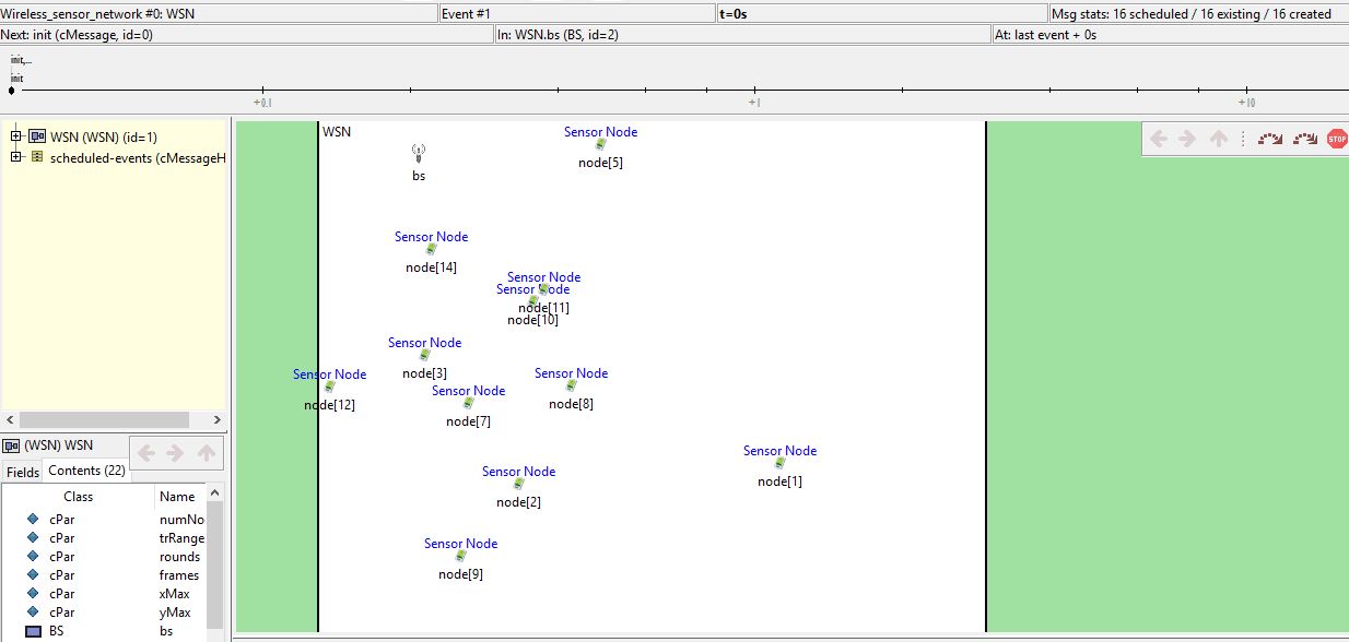
The crucial point in the project is we are sending the live data of the node to the simulator which means whenever the user wants to query the base station it gives the live data. This is responsive to important situations. In this way, APTEEN is both proactive and reactive. Energy consumption is controlled by count time. We have not set the threshold functions but if needed it can be set too. The below image shows the cluster set up of nodes formed.
The coding part of the project is explained below.
#ifndef APTEEN_H_
#define APTEEN_H_
#define NANO 0.001
#define PICO 0.000001
//message types for clusters
#define CL_TOBS 1 // red
#define CL_TOHEAD 2 // green
#define CL_TDMA 3 // blue
#define CL_CHDATA 4 // yellow
//self- message types
#define SMSG_SENDDATA 11
#define SMSG_DATA2BS 12
#define SMSG_STATUS2BS 13
#define SMSG_MAKETDMA 14
#define SMSG_INIT 15
#define SMSG_CHANGESTATUS 16
#define BROADCAST 0
//status
#define STATUS_OK 1
#define STATUS_DEAD 2
// event and times
#define INIT_WAIT 1
struct _node{
int id;
int status;
int outgate;
int hops;
int bcount;
int scount;
int seqNumber;
};
struct _adv{
int id;
double energy;
int status;
double rating;
double xpos;
double ypos;
};
struct _peerInfo{ //Getting the Peer node Infor and status
int id;
double xpos;
double ypos;
}; [28]
The above code shows the setup of routing protocol APTEEN for data transfer. As there are various messages, we have given color code for each type of message. Also, the status ID is defined as 1 for alive and 2 for dead. Each node has its own characteristics at the same time they also have the capability to capture the peer node behavior. The key features of this protocol as follows.
- As this is a combination of proactive and reactive protocols, it responds to any immediate changes and sends periodic data when the user queries the base station.
- In real time scenarios, it offers the user to set the threshold and time flexibility.
- Energy consumption can be highly saved with the help of counters and threshold times.
- Due to its nature of hybrid setup, it is very useful in major applications of WSN.
CHAPTER 7
Interfacing Arduino Data with Simulator Securely
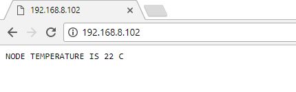
The temperature sensed by the LM35 is now sent to the Arduino Uno and this data is sent to the user system through an Arduino WIFI medium. The communication between the Arduino and the system is done in Arduino IDE and the source code is shown below with explanation.
The code contains the slot for SSID and Password for the same, where the user has to give the SSID and Password of their WIFI and thereby the socket connection in port 80 checks for SSID and if there are a SSID and Password, it will try to connect the same and the Arduino IP is displayed in the serial monitor of IDE. This is a Client-Server setup. The sensed data is processed here with the following calculation shown below:
int sensorReading =(4.3 * analogRead(0) * 100.0) / 1024;
client.print(“NODE TEMPERATURE IS “);
client.print(sensorReading);
client.print(” C “);
Finally, in the serial monitor, it will display the SSID name, Signal Strength and the IP address of the board. Along with this,the keep alive signal is also displayed. Once getting the data in the HTTP browser, next step is to interface the data to the simulator and secure the communication between the nodes to the base station. This is done by creating a socket between the user browser and the interface file where the socket is open and an HTTP GET request is created with the Arduino IP as the source. Once the data that is available in the browser is collected in the Interface file, the same value is sent to the AES function for securing the data which is going to be sent to base station created in the Simulator. The below code shows the process which is explained above.
void arduinodata::readsensornodedata()
{
string request;
string response;
int resp_leng;
char buffer[BUFFERSIZE];
struct sockaddr_in serveraddr;
int sock;
WSADATA wsaData;
char *ipaddress = “192.168.8.102”;
int port = 80;
request+=”GET /test.html HTTP/1.0 ”;
request+=”Host:192.168.8.102 ”; //The IP request sent to browser
request+=” ”;
//init winsock
if (WSAStartup(MAKEWORD(2, 0), &wsaData) != 0)
die_with_wserror(“WSAStartup() failed”);
//open socket
if ((sock = socket(PF_INET, SOCK_STREAM, IPPROTO_TCP)) < 0)
die_with_wserror(“socket() failed”);
//connect
memset(&serveraddr, 0, sizeof(serveraddr));
serveraddr.sin_family = AF_INET;
serveraddr.sin_addr.s_addr = inet_addr(ipaddress);
serveraddr.sin_port = htons((unsigned short) port);
if (connect(sock, (struct sockaddr *) &serveraddr, sizeof(serveraddr)) < 0)
die_with_wserror(“connect() failed”);
//send request
if (send(sock, request.c_str(), request.length(), 0) != request.length())
die_with_wserror(“send() sent a different number of bytes than expected”);
//get response
response = “”;
resp_leng= BUFFERSIZE;
while (resp_leng == BUFFERSIZE){
resp_leng= recv(sock, (char*)&buffer, BUFFERSIZE, 0);
if (resp_leng>0)
response+= string(buffer).substr(0,resp_leng);
} [29]
//display response
int value;
response.c_str();
cout << response << endl;
const char *ct= response.c_str();
int hr= parseInt(ct, &value);
cout << value << endl;
AESENC(hr);
//disconnect
closesocket(sock); [29]
The above code shows that value got from browser is sent to the AES function. Here we are parsing the entire string “Temperature value “to the AES algorithm.
7.1 Security to the Data transferred
As we all know the demand of WSN which is widely being used in all major applications in today’s world especially in areas such as monitoring, tracking and controlling. For all these applications, security is the important requirement. But due to the low processing power and less memory capacity of WSN, all security algorithms will not be suitable and it should be selected precisely based on the application needs. Some of the major threats in security aspects of WSN are as follows. Also, the below -mentioned aspects are possible in the project, if the data from physical node to the simulator is not given security.
Key Security risks in the project:
1. Eaves Drop: It is very easy as we are using wireless sensor networks.
2. Malicious Message in the network: The hackers can easily inject malicious messages in the network. Also, the sensor node constraints make the wireless sensor more likely to be attacked by denial of service attacks in which attackers try to exhaust the resource available to the victim node by sending extra unnecessary packets.
3. Attack on Information: Finally, in sending the information to the monitoring system may be altered, spoofed or vanished.
In many cases, sensors in wireless sensor networks may need to work together to accomplish the task resulting in Sybil attacks which attack the distributing mechanism in the model. So, we have a lot of privacy risks involved in the WSN applications. Generally, the monitoring center has all information, so hackers target this as the victim to get the data, especially by eaves dropping and traffic analysis.
CHAPTER 8
Security Goals for WSN
8.1 Confidentiality:
It is the ability to preserve any messages communicated in the sensor network in a protected way defending from passive or active hackers. The basic methodology is to provide encryption for sensitive data with a secret key that only receiver possesses. [30]
8.2 Integrity:
It is the guarding of data against improper modification or tampering including ensuring information non-repudiation and authenticity.
8.3 Authentication:
It ensures the reliability of the messages by identifying its origin. Data authentication is a property such that message has not been modified while in transit (Data Integrity and the receiving part can verify the source message.[30]
8.4 Availability:
Ensuring timely access and reliability to and use the Information.
8.5 Security Challenges in WSN:
Most routing protocols in WSN have no security implementations and because of this, a hacker can easily enter the routing protocols loop holes.
There are so many threats to WSN which can be divided into many categories.
8.5.1 inside attacker:
This kind of attacker is very dangerous as he/she may have access to encryption keys and other codes used inside the network.
8.5.2 outside attacker:
Outside attacker can do eaves dropping which is already discussed in the above notes. We can easily identify outside attacker if there are any active attacks.
8.5.3 Laptop Class attacker:
These types of attackers are more powerful as they hack access to laptops/systems through which they can control all the nodes deployed in the network.
8.5.4 Mote Class attacker:
These types of attackers gain access to few motes deployed in the network which is having similar capabilities like other motes in the network.
Unlike passive attack, the active attack is more likely to be detected rather than to prevent. There are many categories of active attacks.
A capture of information to produce an unauthorized effect.
This is to deal with Integrity where the messages sent from the sender is either tampered or modified in halfway and when the message received at the receiver end it is not the original message.
8.5.7 Denial of Service (DoS):
This type of attack is attacking the availability service of the network by sending floods of hello packets which will degrade the service and exhaust the energy source of the device.
[30]
8.6 Why AES?
AES -Advanced Encryption Standard. It is approved cryptographic algorithm that can be used to protect our plain text data.
The First and foremost reason for selecting AES in this project is because of its robustness, speed and security. Other reasons are parameter flexibility, possibility of optimizing cipher elements for different environments. One more important reason for selecting AES algorithm is it is efficient in both hardware and software across a variety of platforms. [31]
8.6.1 AES Features:
- It uses a variable block size of 128, 192, 256 bits and key size of 128,192, or 256-bit
- Variable number of rounds (10,12,14)
- 128-bit round key is used for each round such that the calculation is as follows
- 128 bits = 16 bytes= 4 words
- Needs Nr+1 round keys for Nr rounds
- State : 4 by 4 array of bytes ( 128 bits = 16 bytes) [31]
8.6.2 Description of AES:
The below shown is the high-level description of AES working
State = X
AddRoundKey (State, Key )
For r = 1 to Nr-1
SubBytes (State , S -box )
ShiftRows (State )
MixColumns (State)
AddRoundKey (State. Key Nr)
Y= State
[31]
8.6.3 Components explanation in AES:
8.6.3.1 Add round key:
In AES, state is represented as 16 bytes. It consists of the Input to be encrypted along with the Key. The input is 128 bit plain text along with 256 bit key size. The long key and input are put into a 4 * 4-byte box . In each one of these boxes in its state and the cipher key is hexadecimal. Hexadecimal is the easiest way of representing actual 1’s and 0’s which is the very base of a computer code. This concept is very important one in AES algorithm. The diagram shown below tells us how the input is given in a state along with a cipher key. [32]
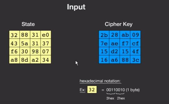
The state goes for encryption process and the cipher key goes for key schedule.
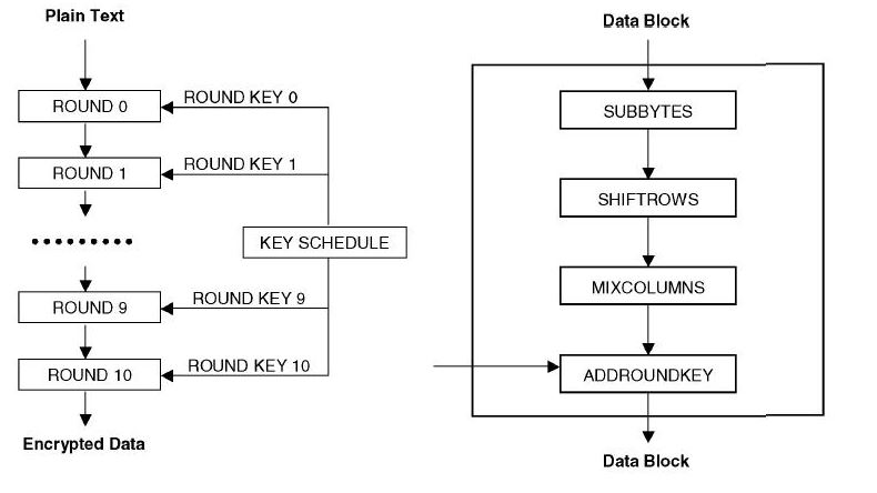
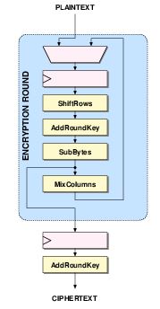
8.6.4 Encryption Process:
The state goes through a number of steps, First and foremost is Add round key step followed by other transformations in the order of SubBytes, ShiftRows, Mix Columns and finally, AddRoundKey.This will be carried on till 13 rounds as the key size we have used here is 256 bit and one final round that is 14 th.to output the cipher text.
8.6.4.1 Sub Bytes: In the code, we have the main function which takes the value to be encrypted and the key size. By using cipher function which has the variable for the input, the round key and the number of rounds.It takes the input in a one -dimensional array and it converts it into 2 -dimensional array. The SubByte takes each block of the state and aligns it in SBOX. SBOX is a box of values that replace the input values. For example, if the input hex decimal value is 32, SBOX takes the 3rd row and 2nd column and the value there replaces the first box in the state. Like this, all the values in each box is replaced by the SBOX values.
In the code, there is a function SBOX which takes the input as state and followed by two nested for loops which have the state variable equal to the value got from SBOX. Below shown is the code for the same.
void arduinodata::SubBytes()
{
int i,j;
for(i=0;i<4;i++)
{
for(j=0;j<4;j++)
{
state[i][j] = getSBoxValue(state[i][j]);
} [33]
The getSBoxValue function simply takes the input and creates local variable which is the huge array of S-Box. Finally, it returns the value of S-Box and this number being the input number along with certain other things to make sure that it is in hexadecimal language.
int arduinodata::getSBoxValue(int num)
{
int sbox[256] = {
//0 1 2 3 4 5 6 7 8 9 A B C D E F
0x63, 0x7c, 0x77, 0x7b, 0xf2, 0x6b, 0x6f, 0xc5, 0x30, 0x01, 0x67, 0x2b, 0xfe, 0xd7, 0xab, 0x76, //0
0xca, 0x82, 0xc9, 0x7d, 0xfa, 0x59, 0x47, 0xf0, 0xad, 0xd4, 0xa2, 0xaf, 0x9c, 0xa4, 0x72, 0xc0, //1
0xb7, 0xfd, 0x93, 0x26, 0x36, 0x3f, 0xf7, 0xcc, 0x34, 0xa5, 0xe5, 0xf1, 0x71, 0xd8, 0x31, 0x15, //2
0x04, 0xc7, 0x23, 0xc3, 0x18, 0x96, 0x05, 0x9a, 0x07, 0x12, 0x80, 0xe2, 0xeb, 0x27, 0xb2, 0x75, //3
0x09, 0x83, 0x2c, 0x1a, 0x1b, 0x6e, 0x5a, 0xa0, 0x52, 0x3b, 0xd6, 0xb3, 0x29, 0xe3, 0x2f, 0x84, //4
0x53, 0xd1, 0x00, 0xed, 0x20, 0xfc, 0xb1, 0x5b, 0x6a, 0xcb, 0xbe, 0x39, 0x4a, 0x4c, 0x58, 0xcf, //5
0xd0, 0xef, 0xaa, 0xfb, 0x43, 0x4d, 0x33, 0x85, 0x45, 0xf9, 0x02, 0x7f, 0x50, 0x3c, 0x9f, 0xa8, //6
0x51, 0xa3, 0x40, 0x8f, 0x92, 0x9d, 0x38, 0xf5, 0xbc, 0xb6, 0xda, 0x21, 0x10, 0xff, 0xf3, 0xd2, //7
0xcd, 0x0c, 0x13, 0xec, 0x5f, 0x97, 0x44, 0x17, 0xc4, 0xa7, 0x7e, 0x3d, 0x64, 0x5d, 0x19, 0x73, //8
0x60, 0x81, 0x4f, 0xdc, 0x22, 0x2a, 0x90, 0x88, 0x46, 0xee, 0xb8, 0x14, 0xde, 0x5e, 0x0b, 0xdb, //9
0xe0, 0x32, 0x3a, 0x0a, 0x49, 0x06, 0x24, 0x5c, 0xc2, 0xd3, 0xac, 0x62, 0x91, 0x95, 0xe4, 0x79, //A
0xe7, 0xc8, 0x37, 0x6d, 0x8d, 0xd5, 0x4e, 0xa9, 0x6c, 0x56, 0xf4, 0xea, 0x65, 0x7a, 0xae, 0x08, //B
0xba, 0x78, 0x25, 0x2e, 0x1c, 0xa6, 0xb4, 0xc6, 0xe8, 0xdd, 0x74, 0x1f, 0x4b, 0xbd, 0x8b, 0x8a, //C
0x70, 0x3e, 0xb5, 0x66, 0x48, 0x03, 0xf6, 0x0e, 0x61, 0x35, 0x57, 0xb9, 0x86, 0xc1, 0x1d, 0x9e, //D
0xe1, 0xf8, 0x98, 0x11, 0x69, 0xd9, 0x8e, 0x94, 0x9b, 0x1e, 0x87, 0xe9, 0xce, 0x55, 0x28, 0xdf, //E
0x8c, 0xa1, 0x89, 0x0d, 0xbf, 0xe6, 0x42, 0x68, 0x41, 0x99, 0x2d, 0x0f, 0xb0, 0x54, 0xbb, 0x16 }; //F
return sbox[num];
}
[33]
8.6.4.2 ShiftRows
Working of ShiftRows: The first row of the state does not move, the second row of the state move by 1 byte, followed by the second row of the state by 2 bytes and finally the third row of the state by 3 bytes.
The source code contains the function ShiftRows which has the state as input and we have a temporary variable along with all other variables that help in execution. The source code for ShiftRows is shown below. [34]
void arduinodata::ShiftRows()
{
unsigned char temp;
temp=state[1][0];
state[1][0]=state[1][1];
state[1][1]=state[1][2];
state[1][2]=state[1][3];
state[1][3]=temp;
temp=state[2][0];
state[2][0]=state[2][2];
state[2][2]=temp;
temp=state[2][1];
state[2][1]=state[2][3];
state[2][3]=temp;
temp=state[3][0];
state[3][0]=state[3][3];
state[3][3]=state[3][2];
state[3][2]=state[3][1];
state[3][1]=temp;
}
[33]
we have cipher function where the ShifRows takes the state as the input arguments.
8.6.4.1 MixColumns:
Working of Mix Columns:It takes each column of the state and multiply withmatrix, finally getting the replaced column. From the source code, the function MixColumns take state as the input along with couple of temporary variables, for loops from 0 to 3 to keep track of columns. With the help of temporary variables, we are assigning it to XOR operations. We also have the “X” time function which returns the bit XOR value of a bit shift operation and a bit AND of a bit shift operation and one times hexadecimal number. [34]
#define xtime(x) ((x<<1) ^ (((x>>7) & 1) * 0x1b))
void arduinodata::MixColumns()
{
int I;
unsigned char Tmp,Tm,t;
for(i=0;i<4;i++)
{
t=state[0][i];
Tmp = state[0][i] ^ state[1][i] ^ state[2][i] ^ state[3][i] ;
Tm = state[0][i] ^ state[1][i] ; Tm = xtime(Tm); state[0][i] ^= Tm ^ Tmp ;
Tm = state[1][i] ^ state[2][i] ; Tm = xtime(Tm); state[1][i] ^= Tm ^ Tmp ;
Tm = state[2][i] ^ state[3][i] ; Tm = xtime(Tm); state[2][i] ^= Tm ^ Tmp ;
Tm = state[3][i] ^ t ; Tm = xtime(Tm); state[3][i] ^= Tm ^ Tmp ;
}
} [33]
8.6.4.1 The AddRoundKey
It takes each value of each row in the state and round key for getting the replacement value. The round key is the key which we provided (256BIT in the project) . The XOR operation is performed between these two values. It gets applied to all columns in the state. In the source code, the AddRoundKey function has the state (the bit XOR of the state and the round key), then RoundKey on figuring it what value it has got. We also need round step as one of the arguments in the function
AddRoundKey
void arduinodata::AddRoundKey(int round)
{
int i,j;
for(i=0;i<4;i++)
{
for(j=0;j<4;j++)
{
state[j][i] ^= RoundKey[round * Nb * 4 + i * Nb + j];
}
}
}
AddRoundKey(0);
for(round=1;round<Nr;round++)
{
SubBytes();
ShiftRows();
MixColumns();
AddRoundKey(round);
}
[33] The above explained are the four major steps of AES algorithm in encryption part. These transformations are applied to the state for 13 more rounds. The final round does not include Mix column transform. [35]
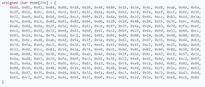
Key Schedule:The key that is inputted in the project is 256 bit. It shows what happens to the key after we put it into the AES box. We are going to take the last column of the Key and going to apply the Rotword. It means placing the top value of the column in the bottom of the column. We’ll take the current Rotword value to the sub byte. Sub Byte is the same process which we discussed earlier. Now, this value is added with three other values. The first one is the column which is 3 columns behind the one which we are currently using (4th column) along with the R column. R column is a table with exponents’ values. The Key schedule uses AES S-box. Now when these three values are added, we‘ll get a new value which is the next step for key schedule. Now, this new column value is added to the column value which is three columns behind this and it gets repeated until we finish 4 steps. Once the 4th column is finished, now this is Rotword and it is sub -Byted, added with 1st column and then Rcon to get the next value in the key schedule. These steps are repeated for next 13 rounds and one final round as we are using 256 bit as the key. [35]
The source code used in the project is shown below.
void arduinodata::KeyExpansion(int Nk,int Nr)
{
int i,j;
unsigned char temp[4],k;
for(i=0;i<Nk;i++)
{
// The First for loop is the actual key //
RoundKey[i*4]=Key[i*4];
RoundKey[i*4+1]=Key[i*4+1];
RoundKey[i*4+2]=Key[i*4+2];
RoundKey[i*4+3]=Key[i*4+3];
}
while (i < (Nb * (Nr+1)))
{
for(j=0;j<4;j++)
{
temp[j]=RoundKey[(i-1) * 4 + j];
}
if (i % Nk == 0)
{
{
k = temp[0];
temp[0] = temp[1];
temp[1] = temp[2];
temp[2] = temp[3];
temp[3] = k;
}
{
temp[0]=getSBoxValue(temp[0]);
temp[1]=getSBoxValue(temp[1]);
temp[2]=getSBoxValue(temp[2]);
temp[3]=getSBoxValue(temp[3]);
}
temp[0] = temp[0] ^ Rcon[i/Nk]; // Adding the Rcon value with the state
}
else if (Nk > 6 && i % Nk == 4) //If not , If Nk is >6 and remainder 4 then it gets plain text value.
{
{
temp[0]=getSBoxValue(temp[0]);
temp[1]=getSBoxValue(temp[1]);
temp[2]=getSBoxValue(temp[2];
temp[3]=getSBoxValue(temp[3]);
}
}
RoundKey[i*4+0] = RoundKey[(i-Nk)*4+0] ^ temp[0];
RoundKey[i*4+1] = RoundKey[(i-Nk)*4+1] ^ temp[1];
RoundKey[i*4+2] = RoundKey[(i-Nk)*4+2] ^ temp[2];
RoundKey[i*4+3] = RoundKey[(i-Nk)*4+3] ^ temp[3];
i++;
}
} [33]
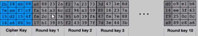
The below pictures show the working model of key schedule in the AES algorithm. The Rcon which is a table of exponent values will look like the same pasted below.
[36]
[35]
The above picture shows the cipher key, going through series of rounds as part of key schedule. As mentioned above, the key schedule happens in AES box.
Summarization of AES working flow is as below.
[37]
[38]
8.6.5 Decryption:
The Decryption is almost same with encryption with few differences. Here first we do InvertShiftRows before the Sub bytes step and the source code for the same is pasted below. The Invert shift rows function declares the same but with backward steps.
void arduinodata::InvShiftRows()
{
unsigned char temp;
// Rotate first row 1 columns to right
temp=state[1][3];
state[1][3]=state[1][2];
state[1][2]=state[1][1];
state[1][1]=state[1][0];
state[1][0]=temp;
// Rotate second row 2 columns to right
temp=state[2][0];
state[2][0]=state[2][2];
state[2][2]=temp;
temp=state[2][1];
state[2][1]=state[2][3];
state[2][3]=temp;
// Rotate third row 3 columns to right
temp=state[3][0];
state[3][0]=state[3][1];
state[3][1]=state[3][2];
state[3][2]=state[3][3];
state[3][3]=temp;
}
[39]
Next step in Decryption is InvertSubBytes. Explanation for the source code is given below.
void arduinodata::InvSubBytes()
{
int i,j;
for(i=0;i<4;i++)
{
for(j=0;j<4;j++)
{
state[i][j] = getSBoxInvert(state[i][j]);
}
}
} [39]
Here it tells that state is equal to the result of invert S-box and this function is the same as the encryption except it has a different S-box now which is used for decryption.
8.6.5.2AddRoundkey:This process is same both in encryption and decryption.
8.6.5.3InvMixColumn:This is a major step which looks normal like mix column function as used in encryption process except with an added function called “Multiply”. The function Multiply has two parameters x and y. Here we return the value of BitXORas shown below.
define Multiply(x,y) (((y & 1) * x) ^ ((y>>1 & 1) * xtime(x)) ^ ((y>>2 & 1) * xtime(xtime(x))) ^ ((y>>3 & 1) * xtime(xtime(xtime(x)))) ^ ((y>>4 & 1) * xtime(xtime(xtime(xtime(x))))))
The above function is placed in a for loop in InvertMix Column function which is placed in the below part.
void arduinodata::InvMixColumns()
{
int i;
unsigned char a,b,c,d;
for(i=0;i<4;i++)
{
a = state[0][i];
b = state[1][i];
c = state[2][i];
d = state[3][i];
state[0][i] = Multiply(a, 0x0e) ^ Multiply(b, 0x0b) ^ Multiply(c, 0x0d) ^ Multiply(d, 0x09);
state[1][i] = Multiply(a, 0x09) ^ Multiply(b, 0x0e) ^ Multiply(c, 0x0b) ^ Multiply(d, 0x0d);
state[2][i] = Multiply(a, 0x0d) ^ Multiply(b, 0x09) ^ Multiply(c, 0x0e) ^ Multiply(d, 0x0b);
state[3][i] = Multiply(a, 0x0b) ^ Multiply(b, 0x0d) ^ Multiply(c, 0x09) ^ Multiply(d, 0x0e);
}
} [39]
The multiply function will be executed 16 times and being in for loop it will get executed 256 times which is a part of the decryption process. Once this step ends, the same step followed by InvertShiftRows, InvertSubBytes and InvertMix columns is routinely repeated for 13 times and finally goes to one last round which is the 14th round in AES decryption process.
In the final round, AddroundKey step is skipped. Now looking at the main function of AES algorithm there are a lot of variables defined. Some of the important variables are Nr and Nk. Nr is the number of rounds which we take in a program that depends on the number of keys used. The number of rounds depends on the key size we used and there are default key sizes for AES (128, 192 and 256 bit). The length of the key is defined as Nk. It is calculated as the key size divided by 32 and the number of rounds equals to the length of the key plus 6. The code for the same is shown below.
void arduinodata::AESENC(int val)
{
int i,Nk=0,Nr=0;
Nr=256;
int l=val;
Nr=Nr+l;
Nk = Nr / 32;
Nr = Nk + 6;
Now we take the hexadecimal input of the key and the value to be encrypted and we split it and put in the array.
Cipher(Nr);
char *st = “data.enc”;
std::ofstream myfile; //Opening the file
myfile.open(st,std::ios_base::app);
printf(“ AES encryption: ”);
printf(“Entering the ciphertext in hexadecimal ”);
for(i=0;i<4*4;i++)
{
printf(“%02x “,out[i]+l); //Printing the encrypted values in Hex format
std::cout << out[i] << std::endl;
myfile <<out[i]+l<<“ ”;
}
printf(“%02x “,out[i]);
myfile.close();
printf(“ ”);
[39]
CHAPTER 9
Results and Conclusion
In the project so far, we have given security to the Application layer in IoT which covers Application, Presentation and Session layers. Some of the key advantages of AES compared to other security algorithms is followed below
1. AES is very strong due to its key length.
2. AES runs faster than many algorithms
3. AES is more efficient than DES and 3DES.
Below is the screenshots of the project simulation and security.
- Arduino data (Temperature Sensor + Arduino Board + Arduino WIFI Medium). The sensor data sensed is passed through Arduino board and through WIFI medium it is synced to the laptop via ethernet cable and the sensor output is seen in an HTTP browser. Below is the screenshot of the data that is visible in the browser.
- The data visible in the browser is now Interfaced to the Simulator (Omnet++) and the node communicating to the base station is secured by applying confidentiality (Encryption and Decryption) AES -256 -bit algorithm.
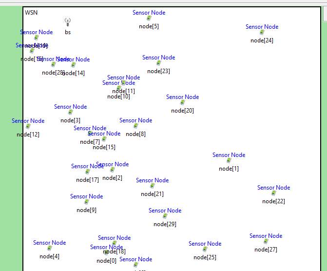
- In the Simulator, 30 virtual nodes are formed along with one base station. All the virtual nodes are assigned with common temperature and this data when communicating to the base station is secured.
APTEEN protocol is applied for data transfer between and among nodes.
Formation of Nodes in Simulator
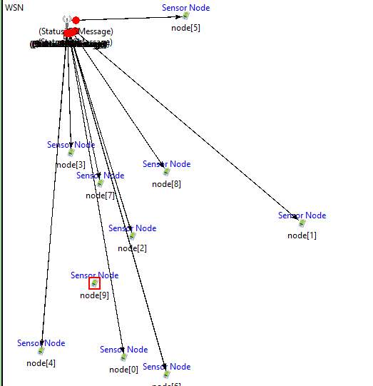
Nodes sending their status to Base Station.
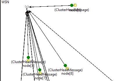
Base Station sending Cluster Head Message to all nodes in the active mode.
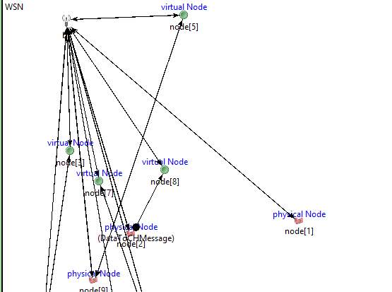
Physical and Virtual Nodes sending data to base station.
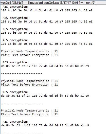
The above shown is the output of the simulation which shows the plain text of the physical and virtual nodes followed by the encrypted text which is of 128 bit for the input data. The encrypted text is shown in 128-bit hex decimal values which are the straightforward way of understanding for the system and the same decimal values in reading in another file.
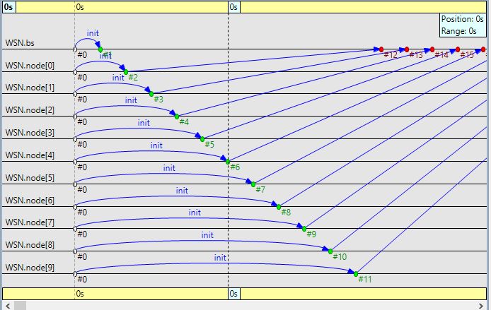
Hence the objective of the project is met where the physical sensor node is interfaced with the simulator formed with virtual nodes and a base station. The communication between the sensor nodes to base station is secured using a security algorithm and the analytics for the same is seen in the graph which is shown below.
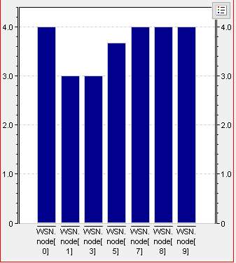
Bar Graph for the Sensor nodes Performance and event log is shown.
The future scope of the project has a lot of improvement in the security domain. We have covered only data confidentiality (Encryption and decryption) in the current project. As we all know security in IoT/WSN is mandatory and challenging task owing to the constraints of WSN nodes characteristic, careful considerations must be taken in designing security to the WSN. Security should be selected in such a way that there is a balanced criterion among the parameters like energy, program memory, temporary memory and execution time. There is a scope for adding Integrity and Verification of each sensor nodes before transmission. Also, we can increase the security in other layers of protocol stack. On the other side, Interfacing of physical and virtual sensor nodes can be done in a much higher standard by inclusion of more physical nodes used for different applications.
Cite This Work
To export a reference to this article please select a referencing stye below:
Related Services
View all


Related Content
All TagsContent relating to: "Internet of Things"
Internet of Things (IoT) is a term used to describe a network of objects connected via the internet. The objects within this network have the ability to share data with each other without the need for human input.
Related Articles

DMCA / Removal Request
If you are the original writer of this dissertation and no longer wish to have your work published on the UKDiss.com website then please: