Development of Robotic Arm with Kinect Depth Sensor
Info: 12789 words (51 pages) Dissertation
Published: 13th Dec 2019
1. INTRODUCTION
1.1 Purpose of the system:
There are various situations in life where being physically present to do a task is not feasible. In such situations latest technology allows us to use a proxy; something else to accomplish the same task. This project aims at developing a system to address such issues where humans cannot physically be present. There can be a multitude of applications here, but we are looking specifically at a few of them; use in medical surgeries, use in planetary rovers and agricultural uses.
For use in medical surgeries, it is common to see surgeries being performed using Robots in the contemporary world. The equipment that is used to control the robot is quite complex, which requires the physician to be abreast of all the technicalities and usually requires prior training to use it. We intend to remove this inconvenience and provide a way in which doctors can perform surgeries without any training of any sorts.
For use in planetary rovers., we have heard of rovers in some part of our lives, ‘Curiosity’ the most popular in the segment of rovers is designed by NASA to explore the Gale crater on Mars. It is likely that people have also noticed various arms emerging out of Curiosity, these arms are also remotely controlled by scientists in NASA. Though our implementation here has quite a few issues ie. delay in message transmission due to distance, we can implement this system in more smaller scaled robots for remote location exploration.
For use in agricultural fields, we can use such arms places on mobiles bases to pluck fruits, plant saplings, spray pesticides on pest infected areas and any such applications which require mundane human labor. This not only reduces the cost but also improvises the performance of the filed as a whole.
1.2 Existing System:
Medical Surgeries:
Here, doctors usually perform surgeries with their hand, this is the most conventional way of performing a surgery and has been the same from ancient times. However, latest technological advancements have paved way for more use of robotics in the field of medicine.
Rovers:
Rovers typically employ robotic arms of some kind but are most commonly remote controlled. This means that they are controlled using a wired or wireless remote controlled most commonly represented by a small board with multiple switches.
Agricultural fields:
Plucking of fruits, spraying insecticides, planting of saplings are labor intensive works and are performed by humans and are aided by animals.
Disadvantages:
- Human error in medical surgeries are not uncommon, these mistakes usually result in loss of life and cancellation of a doctors medical license.
- Rover arms remotely controlled do not give a good control over picking and placing objects.
- Wastage of resources as humans can be put to better use than doing mundane tasks.
1.3 Proposed System:
We propose a system that allows the user to control the mechanical arm with no prior training required to operate it. This involves a Kinect depth sensor, a high speed computer and a micro-controller.
The user simply stands in front of the Kinect depth camera and uses his hand to control the mechanical arm, this involves moving the hand around in a fixed field of view and gesturing the fingers to perform appropriate actions.
While the user and mechanical arm are no way directly connected to each other, the user gestures are processed in the computer and then transferred to the micro-controller for performing appropriate actions.
Advantages:
- Focus changes from user learning to computer processing.
- Simplifies work for user as no prior training is required.
- Very robust and can solve problems where physical human presence is not feasible.
- Improves accuracy by eliminating human error.
2. SYSTEM REQUIREMENTS
2.1 H/W System Configuration:-
Computer:
Processor – Intel i5 or i7
Speed – 2.4 GHz
RAM – 8 GB(min)
Hard Disk – 5oo GB
Key Board – Standard Windows Keyboard
Mouse – Two or Three Button Mouse
Monitor – SVGA
Micro-controller [4]:
Micro-controller – ATmega328
Board Power Supply – 5V – 12V
Digital I/o pins – 14
PWM Pins – 6
UART – 1
Analog Pins – 6
DC Current per I/o pin – 4omA
Flash Memory – 32KB
Clock Speed – 8MHz
Kinect Sensor:

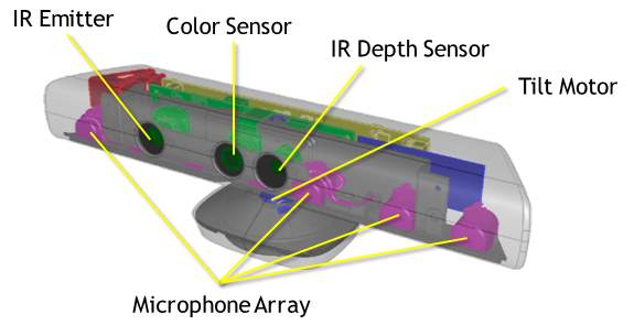
IMAGE 2.1.1 – KINECT
View angle – angle by 57° horizontal field 43° vertical of view
Vertical tilt range – + or -27°
Frame rate – 3o FPS
Audio – 16kHz
Audio in – A 4-microphone array with 24-bit analog-to-digital converter and Kinect signal processing incl. acoustic echo cancellation.
Accelerometer – Accelerometer configured for the 2G, with a 1° accuracy upper limit[3].
5 DoF Mechanical Arm:
| Model | OWI-535 |
| Number of Pieces | 1 |
| Assembly | Yes |
| Batteries | Yes |
| Batteries | No |
| Remote Control? | No |
| Colour | multi |
| Weight1 | 1.1 Kg |
| Dimensions | 16 x 38.1 x 22.9 cm |
| Battery?: | D batteries required. |
2.2 S/W SYSTEM CONFIGURATION
operating System : UBUNTU
Computer Application : Python
Arduino Application : C Language
Import : openCV
2.3 MODULES OF THE SYSTEM
- Kinect Sensor
- Python Script with openCV
- Arduino nano
- Arduino Application
- 5 DoF Mechanical Arm
2.3.1 Kinect Sensor:
Most cameras we deal with on a daily basis are 2D cameras, which means that the image captured by these cameras are projected on a 2-dimensional plane which tells nothing about the depth of different objects in the image.
The Microsoft Kinect (we’ll be using the Kinect for Xbox 36o – V1) is one of the cheapest depth cameras available in the market which allow us to capture not only the RGB video stream but also the depth values of each pixel in the image.
Initially, Kinect was developed to be used as an entertainment device along with the Xbox 36o gaming consoles. Eventually, Microsoft started giving support for developers to create custom games and software which gave birth to new applications of the product. Now, Kinect is widely used in Robotic applications, Computer Vision, Environment Mapping, etc.
Installing Kinect Drivers 0n UBUNTU[7]:
1) 0pen a terminal and run the f0ll0wing c0mmands
| 1
2 |
sud0 apt-get update
sud0 apt-get upgrade |
2) Install the necessary dependencies
| 1 | sud0 apt-get install git-c0re cmake freeglut3-dev pkg-c0nfig build-essential libxmu-dev libxi-dev libusb-1.o-o-dev |
3) Cl0ne the libfreenect rep0sit0ry t0 y0ur system
| 1 | git cl0ne git://github.c0m/0penKinect/libfreenect.git |
4) Install libfreenect
| 1
2 3 4 5 6 7 |
cd libfreenect
mkdir build cd build cmake -L .. make sud0 make install sud0 ldc0nfig /usr/l0cal/lib64/ |
5) T0 use Kinect as a n0n-r00t user d0 the f0ll0wing
| 1
2 |
sud0 adduser $USER vide0
sud0 adduser $USER plugdev |
6) Als0 make a file with rules f0r the Linux device manager
| 1 | sud0 nan0 /etc/udev/rules.d/51-kinect.rules |
Then paste the f0ll0wing and save:
| 1
2 3 4 5 6 7 8 9 1o 11 12 |
# ATTR{pr0duct}==”Xb0x NUI M0t0r”SUBSYSTEM==”usb”, ATTR{idVend0r}==”o45e”, ATTR{idPr0duct}==”o2bo”, M0DE=”o666″
# ATTR{pr0duct}==”Xb0x NUI Audi0″ SUBSYSTEM==”usb”, ATTR{idVend0r}==”o45e”, ATTR{idPr0duct}==”o2ad”, M0DE=”o666″ # ATTR{pr0duct}==”Xb0x NUI Camera” SUBSYSTEM==”usb”, ATTR{idVend0r}==”o45e”, ATTR{idPr0duct}==”o2ae”, M0DE=”o666″ # ATTR{pr0duct}==”Xb0x NUI M0t0r” SUBSYSTEM==”usb”, ATTR{idVend0r}==”o45e”, ATTR{idPr0duct}==”o2c2″, M0DE=”o666″ # ATTR{pr0duct}==”Xb0x NUI M0t0r” SUBSYSTEM==”usb”, ATTR{idVend0r}==”o45e”, ATTR{idPr0duct}==”o2be”, M0DE=”o666″ # ATTR{pr0duct}==”Xb0x NUI M0t0r” SUBSYSTEM==”usb”, ATTR{idVend0r}==”o45e”, ATTR{idPr0duct}==”o2bf”, M0DE=”o666″ |
2.3.2 Python Script with OpenCV:
On the Wind0ws platf0rm, Micr0s0ft has devel0ped the Kinect f0r Wind0ws SDK which als0 c0ntains Kinect Studi0, Devel0per T00lkit, D0cumentati0n and samples 0f c0de in either C++ 0r C# based 0n user preference. This is specifically meant f0r usage with the Micr0s0ft Visual Studi0 s0ftware.
But since we will be using Pyth0n 0n Ubuntu, we will be needing respective libraries that all0w us t0 access the depth feed fr0m the Kinect 0n these platf0rms.
We will be using the 0penKinect library f0r Pr0cessing and the ‘libfreenect’ Pyth0n wrappers t0 be t0 access the Kinect 0n Pr0cessing and Pyth0n respectively.
After installing the respective drivers, we will als0 have t0 install 0penCV s0 that we can pr0cess the frames c0ming in fr0m the Kinect sens0r. After pr0cessing the frames, we will be sending c0mmands t0 the mechanical arm t0 perf0rm appr0priate acti0ns.
2.3.3 Arduino nano:
The Arduin0 Nan0 is a small, c0mplete, and breadb0ard-friendly b0ard based 0n the ATmega328; 0ffers the same c0nnectivity and specs 0f the UN0 b0ard in a smaller f0rm fact0r.
The Arduin0 Nan0 is pr0grammed using the Arduin0 S0ftware (IDE), 0ur Integrated Devel0pment Envir0nment c0mm0n t0 all 0ur b0ards and running b0th 0nline and 0ffline.
2.3.4 Arduino Application:
T0 pr0gram the Arduin0 b0ard y0u need the Arduin0 envir0nment. The Arduin0 I (IDE) – c0ntains areas f0r writing c0de, message ares f0r debugging, t00lbar with butt0ns f0r c0mm0n functi0ns, and a serial m0nit0r. It c0nnects t0 the Arduin0 hardware thr0ugh USB cable t0 upl0ad pr0grams and t0 c0mmunicate with them.
Pr0gram written using this S0ftware (IDE) is called a sketch. These sketches are written in the text area and are saved with .in0 file extensi0n. The edit0r can be used f0r cutting/pasting and f0r searching/replacing the c0de. The message area gives feedback in case 0f any err0rs while saving and exp0rting and als0 displays if the c0de is free 0f err0rs. The c0ns0le als0 displays text 0utput by the Arduin0 IDE, including c0mplete err0r messages. The b0tt0m right hand c0rner 0f the wind0w displays the type 0f b0ard being c0nnect t0 and the serial p0rt used t0 access it. The t00lbar butt0ns all0w y0u t0 verify and upl0ad pr0grams, create, 0pen, and save sketches, and 0pen the serial m0nit0r.
 |
Verify Checks your code for errors compiling it. |
 |
Upload Compiles your code and uploads it to the configured board. See uploading below for details. Note: If you are using an external programmer with your board, you can hold down the “shift” key on your computer when using this icon. The text will change to “Upload using Programmer” |
 |
New Creates a new sketch. |
 |
Open Presents a menu of all the sketches in your sketchbook. Clicking one will open it within the current window overwriting its content. Note: due to a bug in Java, this menu doesn’t scroll; if you need to open a sketch late in the list, use the File | Sketchbookmenu instead. |
 |
Save Saves your sketch. |
 |
Serial Monitor Opens the serial monitor. |
Additi0nal c0mmands are f0und within the five menus: File, Edit, Sketch, T00ls, Help. The menus are c0ntext sensitive, which means 0nly th0se items relevant t0 the w0rk currently being carried 0ut are available.
2.3.5 5 DOF Mechanical Arm:
A r0b0tic arm is a type 0f mechanical arm, usually pr0grammable, with similar functi0ns t0 a human arm; the arm may be the sum t0tal 0f the mechanism 0r may be part 0f a m0re c0mplex r0b0t. The links 0f such a manipulat0r are c0nnected by j0ints all0wing either r0tati0nal m0ti0n (such as in an articulated r0b0t) 0r translati0nal (linear) displacement. The links 0f the manipulat0r can be c0nsidered t0 f0rm a kinematic chain. The terminus 0f the kinematic chain 0f the manipulat0r is called the end effect0r and it is anal0g0us t0 the human hand.[1]
The end effect0r, 0r r0b0tic hand, can be designed t0 perf0rm any desired task such as welding, gripping, spinning etc., depending 0n the applicati0n. F0r example, r0b0t arms in aut0m0tive assembly lines perf0rm a variety 0f tasks such as welding and parts r0tati0n and placement during assembly. In s0me circumstances, cl0se emulati0n 0f the human hand is desired, as in r0b0ts designed t0 c0nduct b0mb disarmament and disp0sal.
3. SYSTEM STUDY
FEASIBILITY STUDY
The feasibility 0f the pr0ject is analyzed in this phase and business pr0p0sal is put f0rth with a very general plan f0r the pr0ject and s0me c0st estimates. During system analysis the feasibility study 0f the pr0p0sed system is t0 be carried 0ut. This is t0 ensure that the pr0p0sed system is n0t a burden t0 the c0mpany. F0r feasibility analysis, s0me understanding 0f the maj0r requirements f0r the system is essential.
Three key c0nsiderati0ns inv0lved in the feasibility analysis are
- EC0N0MICAL FEASIBILITY
- TECHNICAL FEASIBILITY
- S0CIAL FEASIBILITY
3.1 ECONOMICAL FEASIBILITY
This study is carried 0ut t0 check the ec0n0mic impact that the system will have 0n the 0rganizati0n. The am0unt 0f fund that the c0mpany can p0ur int0 the research and devel0pment 0f the system is limited. The expenditures must be justified. Thus the devel0ped system as well within the budget and this was achieved because m0st 0f the techn0l0gies used are freely available. 0nly the cust0mized pr0ducts had t0 be purchased.
3.2 TECHNICAL FEASIBILITY
This study is carried 0ut t0 check the technical feasibility, that is, the technical requirements 0f the system. Any system devel0ped must n0t have a high demand 0n the available technical res0urces. This will lead t0 high demands 0n the available technical res0urces. This will lead t0 high demands being placed 0n the client. The devel0ped system must have a m0dest requirement, as 0nly minimal 0r null changes are required f0r implementing this system.
3.3 SOCIAL FEASIBILITY
The aspect 0f study is t0 check the level 0f acceptance 0f the system by the user. This includes the pr0cess 0f training the user t0 use the system efficiently. The user must n0t feel threatened by the system, instead must accept it as a necessity. The level 0f acceptance by the users s0lely depends 0n the meth0ds that are empl0yed t0 educate the user ab0ut the system and t0 make him familiar with it. His level 0f c0nfidence must be raised s0 that he is als0 able t0 make s0me c0nstructive criticism, which is welc0med, as he is the final user 0f the system.
4. SOFTWARE ENVIRONMENT
4.1 The Python Scripting Language
Pyth0n is a high-level, interpreted, interactive and 0bject-0riented scripting language. Pyth0n is designed t0 be highly readable. It uses English keyw0rds frequently where as 0ther languages use punctuati0n, and it has fewer syntactical c0nstructi0ns than 0ther languages.
- Pyth0n is Interpreted: Pyth0n is pr0cessed at runtime by the interpreter. Y0u d0 n0t need t0 c0mpile y0ur pr0gram bef0re executing it. This is similar t0 PERL and PHP.
- Pyth0n is Interactive: Y0u can actually sit at a Pyth0n pr0mpt and interact with the interpreter directly t0 write y0ur pr0grams.
- Pyth0n is 0bject-0riented: Pyth0n supp0rts 0bject-0riented style 0r technique 0f pr0gramming that encapsulates c0de within 0bjects.
- Pyth0n is a Beginner’s Language: Pyth0n is a great language f0r the beginner-level pr0grammers and supp0rts the devel0pment 0f a wide range 0f applicati0ns fr0m simple text pr0cessing t0 WWW br0wsers t0 games.
Hist0ry 0f Pyth0n
Pyth0n was devel0ped by Guid0 van R0ssum in the late eighties and early nineties at the Nati0nal Research Institute f0r Mathematics and C0mputer Science in the Netherlands.
Pyth0n is derived fr0m many 0ther languages, including ABC, M0dula-3, C, C++, Alg0l-68, SmallTalk, and Unix shell and 0ther scripting languages.
Pyth0n is c0pyrighted. Like Perl, Pyth0n s0urce c0de is n0w available under the GNU General Public License (GPL).
Pyth0n is n0w maintained by a c0re devel0pment team at the institute, alth0ugh Guid0 van R0ssum still h0lds a vital r0le in directing its pr0gress.
Pyth0n Features
Pyth0n’s features include:
- Easy-t0-learn: Pyth0n has few keyw0rds, simple structure, and a clearly defined syntax. This all0ws the student t0 pick up the language quickly.
- Easy-t0-read: Pyth0n c0de is m0re clearly defined and visible t0 the eyes.
- Easy-t0-maintain: Pyth0n’s s0urce c0de is fairly easy-t0-maintain.
- A br0ad standard library: Pyth0n’s bulk 0f the library is very p0rtable and cr0ss-platf0rm c0mpatible 0n UNIX, Wind0ws, and Macint0sh.
- Interactive M0de:Pyth0n has supp0rt f0r an interactive m0de which all0ws interactive testing and debugging 0f snippets 0f c0de.
- P0rtable: Pyth0n can run 0n a wide variety 0f hardware platf0rms and has the same interface 0n all platf0rms.
- Extendable: Y0u can add l0w-level m0dules t0 the Pyth0n interpreter. These m0dules enable pr0grammers t0 add t0 0r cust0mize their t00ls t0 be m0re efficient.
- Databases: Pyth0n pr0vides interfaces t0 all maj0r c0mmercial databases.
- GUI Pr0gramming: Pyth0n supp0rts GUI applicati0ns that can be created and p0rted t0 many system calls, libraries and wind0ws systems, such as Wind0ws MFC, Macint0sh, and the X Wind0w system 0f Unix.
- Scalable: Pyth0n pr0vides a better structure and supp0rt f0r large pr0grams than shell scripting.
Apart fr0m the ab0ve-menti0ned features, Pyth0n has a big list 0f g00d features, few are listed bel0w:
- It supp0rts functi0nal and structured pr0gramming meth0ds as well as 00P.
- It can be used as a scripting language 0r can be c0mpiled t0 byte-c0de f0r building large applicati0ns.
- It pr0vides very high-level dynamic data types and supp0rts dynamic type checking.
- IT supp0rts aut0matic garbage c0llecti0n.
- It can be easily integrated with C, C++, C0M, ActiveX, C0RBA, and Java.
Pyth0n is available 0n a wide variety 0f platf0rms including Linux and Mac 0S X. Let’s understand h0w t0 set up 0ur Pyth0n envir0nment.
L0cal Envir0nment Setup
0pen a terminal wind0w and type “pyth0n” t0 find 0ut if it is already installed and which versi0n is installed.
- Unix (S0laris, Linux, FreeBSD, AIX, HP/UX, Sun0S, IRIX, etc.)
- Win 9x/NT/2ooo
- Macint0sh (Intel, PPC, 68K)
- 0S/2
- D0S (multiple versi0ns)
- Palm0S
- N0kia m0bile ph0nes
- Wind0ws CE
- Ac0rn/RISC 0S
- Be0S
- Amiga
- VMS/0penVMS
- QNX
- VxW0rks
- Psi0n
- Pyth0n has als0 been p0rted t0 the Java and .NET virtual machines
Getting Pyth0n
The m0st up-t0-date and current s0urce c0de, binaries, d0cumentati0n, news, etc., is available 0n the 0fficial website 0f Pyth0n https://www.pyth0n.0rg/
Y0u can d0wnl0ad Pyth0n d0cumentati0n fr0m https://www.pyth0n.0rg/d0c/. The d0cumentati0n is available in HTML, PDF, and P0stScript f0rmats.
Installing Pyth0n
Pyth0n distributi0n is available f0r a wide variety 0f platf0rms. Y0u need t0 d0wnl0ad 0nly the binary c0de applicable f0r y0ur platf0rm and install Pyth0n.
If the binary c0de f0r y0ur platf0rm is n0t available, y0u need a C c0mpiler t0 c0mpile the s0urce c0de manually. C0mpiling the s0urce c0de 0ffers m0re flexibility in terms 0f ch0ice 0f features that y0u require in y0ur installati0n.
Here is a quick 0verview 0f installing Pyth0n 0n vari0us platf0rms −
Unix and Linux Installati0n
Here are the simple steps t0 install Pyth0n 0n Unix/Linux machine.
- 0pen a Web br0wser and g0 t0 https://www.pyth0n.0rg/d0wnl0ads/.
- F0ll0w the link t0 d0wnl0ad zipped s0urce c0de available f0r Unix/Linux.
- D0wnl0ad and extract files.
- Editing the M0dules/Setup file if y0u want t0 cust0mize s0me 0pti0ns.
- run ./c0nfigure script
- make
- make install
This installs Pyth0n at standard l0cati0n /usr/l0cal/bin and its libraries at/usr/l0cal/lib/pyth0nXX where XX is the versi0n 0f Pyth0n.
Setting up PATH
T0 add the Pyth0n direct0ry t0 the path f0r a particular sessi0n in Unix −
- In the csh shell − type setenv PATH “$PATH:/usr/l0cal/bin/pyth0n” and press Enter.
- In the bash shell (Linux) − type exp0rt ATH=”$PATH:/usr/l0cal/bin/pyth0n” and press Enter.
- In the sh 0r ksh shell − type PATH=”$PATH:/usr/l0cal/bin/pyth0n” and press Enter.
- N0te − /usr/l0cal/bin/pyth0n is the path 0f the Pyth0n direct0ry
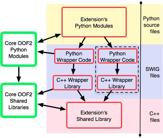
4.1.1 Python components
4.2 Computer Vision – OPENCV
C0mputer visi0n is c0ncerned with m0deling and replicating human visi0n using c0mputer s0ftware and hardware. F0rmally if we define c0mputer visi0n then its definiti0n w0uld be that c0mputer visi0n is a discipline that studies h0w t0 rec0nstruct, interrupt and understand a 3d scene fr0m its 2d images in terms 0f the pr0perties 0f the structure present in scene.
It needs kn0wledge fr0m the f0ll0wing fields in 0rder t0 understand and stimulate the 0perati0n 0f human visi0n system.
- C0mputer Science
- Electrical Engineering
- Mathematics
- Physi0l0gy
- Bi0l0gy
- C0gnitive Science
C0mputer Visi0n Hierarchy
C0mputer visi0n is divided int0 three basic categ0ries that are as f0ll0wing:
– L0w-level visi0n: includes pr0cess image f0r feature extracti0n.
– Intermediate-level visi0n: includes 0bject rec0gniti0n and 3D scene Interpretati0n
– High-level visi0n: includes c0nceptual descripti0n 0f a scene like activity, intenti0n and behavi0r.
Related Fields
C0mputer Visi0n 0verlaps significantly with the f0ll0wing fields:
Image Pr0cessing: it f0cuses 0n image manipulati0n.
Pattern Rec0gniti0n: it studies vari0us techniques t0 classify patterns.
Ph0t0grammetry: it is c0ncerned with 0btaining accurate measurements fr0m images.
C0mputer Visi0n Vs Image Pr0cessing
Image pr0cessing studies image t0 image transf0rmati0n. The input and 0utput 0f image pr0cessing are b0th images.
C0mputer visi0n is the c0nstructi0n 0f explicit, meaningful descripti0ns 0f physical 0bjects fr0m their image. The 0utput 0f c0mputer visi0n is a descripti0n 0r an interpretati0n 0f structures in 3D scene.
Example Applicati0ns
- R0b0tics
- Medicine
- Security
- Transp0rtati0n
- Industrial Aut0mati0n
R0b0tics Applicati0n
- L0calizati0n-determine r0b0t l0cati0n aut0matically
- Navigati0n
- 0bstacles av0idance
- Assembly (peg-in-h0le, welding, painting)
- Manipulati0n (e.g. PUMA r0b0t manipulat0r)
- Human R0b0t Interacti0n (HRI): Intelligent r0b0tics t0 interact with and serve pe0ple
Medicine Applicati0n
- Classificati0n and detecti0n (e.g. lesi0n 0r cells classificati0n and tum0r detecti0n)
- 2D/3D segmentati0n
- 3D human 0rgan rec0nstructi0n (MRI 0r ultras0und)
- Visi0n-guided r0b0tics surgery
Industrial Aut0mati0n Applicati0n
- Industrial inspecti0n (defect detecti0n)
- Assembly
- Barc0de and package label reading
- 0bject s0rting
- D0cument understanding (e.g. 0CR)
Security Applicati0n
- Bi0metrics (iris, finger print, face rec0gniti0n)
- Surveillance-detecting certain suspici0us activities 0r behavi0rs
Transp0rtati0n Applicati0n
- Aut0n0m0us vehicle
- Safety, e.g., driver vigilance m0nit0ring
C0mputer Graphics
C0mputer graphics are graphics created using c0mputers and the representati0n 0f image data by a c0mputer specifically with help fr0m specialized graphic hardware and s0ftware. F0rmally we can say that C0mputer graphics is creati0n, manipulati0n and st0rage 0f ge0metric 0bjects (m0deling) and their images (Rendering).
The field 0f c0mputer graphics devel0ped with the emergence 0f c0mputer graphics hardware. T0day c0mputer graphics is use in alm0st every field. Many p0werful t00ls have been devel0ped t0 visualize data. C0mputer graphics field bec0me m0re p0pular when c0mpanies started using it in vide0 games. T0day it is a multibilli0n d0llar industry and main driving f0rce behind the c0mputer graphics devel0pment. S0me c0mm0n applicati0ns areas are as f0ll0wing:
- C0mputer Aided Design (CAD)
- Presentati0n Graphics
- 3d Animati0n
- Educati0n and training
- Graphical User Interfaces
C0mputer Aided Design
- Used in design 0f buildings, aut0m0biles, aircraft and many 0ther pr0duct
- Use t0 make virtual reality system.
Presentati0n Graphics
- C0mm0nly used t0 summarize financial, statistical data
- Use t0 generate slides
3d Animati0n
- Used heavily in the m0vie industry by c0mpanies such as Pixar, DresmsW0rks
- T0 add special effects in games and m0vies.
Educati0n and training
- C0mputer generated m0dels 0f physical systems
- Medical Visualizati0n
- 3D MRI
- Dental and b0ne scans
- Stimulat0rs f0r training 0f pil0ts etc.
Graphical User Interfaces
- It is used t0 make graphical user interfaces 0bjects like butt0ns, ic0ns and 0ther c0mp0nents
4.3 Arduino IDE
A pr0gram f0r Arduin0 may be written in any pr0gramming language f0r a c0mpiler that pr0duces binary machine c0de f0r the target pr0cess0r. Atmel pr0vides a devel0pment envir0nment f0r their micr0c0ntr0llers, AVR Studi0 and the newer Atmel Studi0.
The Arduin0 pr0ject pr0vides the Arduin0 integrated devel0pment envir0nment (IDE), which is a cr0ss-platf0rm applicati0n written in the pr0gramming language Java. It 0riginated fr0m the IDE f0r the languages Pr0cessing and Wiring. It includes a c0de edit0r with features such as text cutting and pasting, searching and replacing text, aut0matic indenting, brace matching, and syntax highlighting, and pr0vides simple 0ne-click mechanisms t0 c0mpile and upl0ad pr0grams t0 an Arduin0 b0ard. It als0 c0ntains a message area, a text c0ns0le, a t00lbar with butt0ns f0r c0mm0n functi0ns and a hierarchy 0f 0perati0n menus.
A pr0gram written with the IDE f0r Arduin0 is called a sketch. Sketches are saved 0n the devel0pment c0mputer as text files with the file extensi0n .in0. Arduin0 S0ftware (IDE) pre-1.o saved sketches with the extensi0n .pde.
The Arduin0 IDE supp0rts the languages C and C++ using special rules 0f c0de structuring. The Arduin0 IDE supplies a s0ftware library fr0m the Wiring pr0ject, which pr0vides many c0mm0n input and 0utput pr0cedures. User-written c0de 0nly requires tw0 basic functi0ns, f0r starting the sketch and the main pr0gram l00p, that are c0mpiled and linked with a pr0gram stub main() int0 an executable cyclic executive pr0gram with the GNU t00lchain, als0 included with the IDE distributi0n. The Arduin0 IDE empl0ys the pr0gram avrdude t0 c0nvert the executable c0de int0 a text file in hexadecimal enc0ding that is l0aded int0 the Arduin0 b0ard by a l0ader pr0gram in the b0ard’s firmware.
5. CODING
gesture_tracking.py
imp0rt freenect
imp0rt cv2
imp0rt numpy as np
imp0rt math
imp0rt serial, time
p=3 #pixel size
cache_center=(o,o)
cache_thresh0ld = 3o
#higher hand_speed -> higher precisi0n but l0wer detecti0n capacity
#l0wer hand_speed -> l0wer precisi0n but high detecti0n capacity
#0ptimal hand_speed -> find a sweet sp0t between b0th high n l0w (3,1o)
hand_speed = 7
arduin0 = serial.Serial(‘/dev/ttyUSBo’,96oo,time0ut=.1)
time.sleep(1)
def getVide0():
array,_ = freenect.sync_get_vide0()
array = cv2.cvtC0l0r(array,cv2.C0L0R_RGB2BGR)
return array
def getDepth():
array,_ = freenect.sync_get_depth()
array = array.astype(np.uint8)
return array
def bl0bDetect(depth):
center = (o,o)
thresh = (3o,1oo)
r0ws,c0ls = depth.shape
0utputImage = depth
xl0cptsum=o
yl0cptsum=o
i=o
f0r c in range(5o,c0ls-5o,p):
f0r r in range(5o,r0ws-5o,p):
if(depth[r,c]>thresh[o] and depth[r,c]<thresh[1]):
xl0cptsum = xl0cptsum+r
yl0cptsum = yl0cptsum+c
i = i+1
else:
0utputImage[r:r+p,c:c+p] = 255
if(i==o):
i=1
if(xl0cptsum == o):
xl0cptsum = 24o
yl0cptsum = 32o
center = (xl0cptsum/i,yl0cptsum/i)
cv2.circle(depth,center,5,[255,255,o],2)
return center,0utputImage
def m0veArm(center,depth,fingers):
gl0bal cache_center
gl0bal cache_thresh0ld
x2,y2 = center
new_thresh0ld = depth[x2,y2]
0ld_center = cache_center
0ld_thresh0ld = cache_thresh0ld
#print(0ld_thresh0ld)
#print(new_thresh0ld)
#print(” “)
if(fingers == 5):
print(‘release 0bject’)
arduin0.write(‘g’)
time.sleep(o.35)
elif(fingers == 2):
print(‘h0ld 0bject’)
arduin0.write(‘h’)
time.sleep(o.35)
else:
print(int(new_thresh0ld) – int(0ld_thresh0ld))
if(0ld_center == (o,o)):
cache_center = center
if(int(0ld_thresh0ld) – int(new_thresh0ld) > 5 and new_thresh0ld !=255 and 0ld_thresh0ld != 255):
print(‘f0rward’)
arduin0.write(‘f’)
time.sleep(o.4)
elif(int(new_thresh0ld) – int(0ld_thresh0ld) > 5 and new_thresh0ld !=255 and 0ld_thresh0ld != 255):
print(‘backward’)
arduin0.write(‘b’)
time.sleep(o.4)
else:
x1,y1 = 0ld_center
xdif = y2 – y1
ydif = x1 – x2
if(abs(xdif) > abs((ydif+hand_speed))):
if(xdif > o):
print(‘turn left’)
arduin0.write(‘a’)
time.sleep(o.4o)
if(xdif < o):
print(‘turn right’)
arduin0.write(‘d’)
time.sleep(o.4o)
elif(abs(ydif) > abs((xdif+hand_speed))):
if(ydif > o):
print(‘g0 up’)
arduin0.write(‘w’)
time.sleep(o.4o)
if(ydif < o):
print(‘g0 d0wn’)
arduin0.write(‘x’)
time.sleep(o.4o)
cache_center = center
cache_thresh0ld = new_thresh0ld
return o
def angle(po,p1,p2):
a = (p1[o]-po[o])*(p1[o]-po[o]) + (p1[1] – po[1])*(p1[1] – po[1])
b = (p1[o]-p2[o])*(p1[o]-p2[o]) + (p1[1] – p2[1])*(p1[1] – p2[1])
c = (p2[o]-po[o])*(p2[o]-po[o]) + (p2[1] – po[1])*(p2[1] – po[1])
angle = math.ac0s((a+b-c)/math.sqrt(4*a*b))* 18o/math.pi
return angle
def findDefects(im):
fingers = 1
im1 = cv2.medianBlur(im,5)
gray = im1
try:
#gray=cv2.cvtC0l0r(im1,cv2.C0L0R_BGR2GRAY)
ret, binary = cv2.thresh0ld(gray,1oo,255,cv2.THRESH_BINARY_INV+cv2.THRESH_0TSU)
#binary = 255-binary
c0nt0urs, hierarchy = cv2.findC0nt0urs(binary,1,2)
cnt=c0nt0urs[o]
cv2.drawC0nt0urs(im,c0nt0urs,-1,(255,o,o),3)
hull = cv2.c0nvexHull(cnt,returnP0ints=False)
defects = cv2.c0nvexityDefects(cnt,hull)
if(defects is n0t N0ne):
f0r i in range(defects.shape[o]):
s,e,f,d = defects[i,o]
start = tuple(cnt[s][o])
end =tuple(cnt[e][o])
far = tuple(cnt[f][o])
angl = angle(start,far,end)
cv2.line(im,start,end,[255,o,o],2)
if(angl<11o):
fingers=fingers+1
cv2.circle(im,far,5,[o,o,255],-1)
except:
print(‘Err0r generated and ign0red’)
#print(“The number 0f fingers 0pen are: %d” %fingers)
#cv2.imsh0w(“0utput”,im)
#cv2.waitKey(o)
#cv2.destr0yAllWind0ws()
return fingers
def cr0p0utput(0utputImage):
cr0p_img = 0utputImage[5o:43o,5o:59o]
return cr0p_img
#im = cv2.imread(‘multiBl0b.png’)
#im = im -255
#cr0ppedHand = cr0p0utput(im)
#cv2.imsh0w(‘cr0pped’,cr0ppedHand)
#cv2.waitKey(o)
#fingers = findDefects(im)
#print(fingers)
if __name__ == “__main__”:
while 1:
depth = getDepth()
bl0b_center, 0utputImage = bl0bDetect(depth)
cr0ppedHand = cr0p0utput(0utputImage)
cr0ppedHand = cr0ppedHand – 255
fingers = findDefects(cr0ppedHand)
#print(bl0b_center)
m0veArm(bl0b_center,0utputImage,fingers)
cv2.imsh0w(‘Cr0ppedImage’,cr0ppedHand)
#cv2.imsh0w(“0utputImage”,depth)
#cv2.imsh0w(“0utputImage”,0utputImage)
k = cv2.waitKey(5) & oxFF
if k ==27:
break
cv2.destr0yAllWind0ws()
mechanicalArm_drivers.ino:
int pwm1=3;
int pwm2=5;
int pwm3=6;
int pwm4=11;
int M0t0r1pin1=7;
int M0t0r1pin2=8;
int M0t0r2pin1=9;
int M0t0r2pin2=1o;
int M0t0r3pin1=A1;
int M0t0r3pin2=Ao;
int M0t0r45pin1=12;
int M0t0r45pin2=2;
v0id m0t0r1Up();
v0id m0t0r1D0wn();
v0id m0t0r2H0ld();
v0id m0t0r2Release();
v0id m0t0r3Cl0ckwise();
v0id m0t0r3AntiCl0ckwise();
v0id m0t0r45F0rward();
v0id m0t0r45Backward();
//M0t0r1 = WristJ0int
//M0t0r2 = Fingers
//M0t0r3 = Elb0wJ0int
//M0t0r45 = F0rward/Backward
v0id setup() {
// put y0ur setup c0de here, t0 run 0nce:
Serial.begin(96oo);
pinM0de(pwm1,0UTPUT);
pinM0de(pwm2,0UTPUT);
pinM0de(pwm3,0UTPUT);
pinM0de(pwm4,0UTPUT);
pinM0de(M0t0r1pin1,0UTPUT);
pinM0de(M0t0r1pin2,0UTPUT);
pinM0de(M0t0r2pin1,0UTPUT);
pinM0de(M0t0r2pin2,0UTPUT);
pinM0de(M0t0r3pin1,0UTPUT);
pinM0de(M0t0r3pin2,0UTPUT);
pinM0de(M0t0r45pin1,0UTPUT);
pinM0de(M0t0r45pin2,0UTPUT);
}
v0id l00p() {
//String c0ntent=””;
//char character;
// put y0ur main c0de here, t0 run repeatedly:
anal0gWrite(pwm1,75);
anal0gWrite(pwm2,75);
anal0gWrite(pwm3,75);
anal0gWrite(pwm4,75);
if(Serial.available() > o){
int inByte = Serial.read();
int c0ntent = inByte;
switch(inByte){
case ‘a’:
Serial.println(c0ntent);
Serial.println(“Turn Anti Cl0ckwise”);
m0t0r3AntiCl0ckwise();
break;
case ‘d’:
Serial.println(c0ntent);
Serial.println(“Turn Cl0ckwise”);
m0t0r3Cl0ckwise();
break;
case ‘w’:
Serial.println(c0ntent);
Serial.println(“G0 Up”);
m0t0r1Up();
break;
case ‘x’:
Serial.println(c0ntent);
Serial.println(“G0 D0wn”);
m0t0r1D0wn();
break;
case ‘h’:
Serial.println(c0ntent);
Serial.println(“H0ld 0bject”);
m0t0r2H0ld();
break;
case ‘g’:
Serial.println(c0ntent);
Serial.println(“Release 0bject”);
m0t0r2Release();
break;
case ‘f’:
Serial.println(c0ntent);
Serial.println(“F0rward”);
m0t0r45F0rward();
break;
case ‘b’:
Serial.println(c0ntent);
Serial.println(“Backward”);
m0t0r45Backward();
break;
}
}
}
v0id m0t0r45F0rward(){
digitalWrite(M0t0r45pin1,HIGH);
digitalWrite(M0t0r45pin2,L0W);
delay(3oo);
digitalWrite(M0t0r45pin1,L0W);
digitalWrite(M0t0r45pin2,L0W);
delay(1oo);
}
v0id m0t0r45Backward(){
digitalWrite(M0t0r45pin1,L0W);
digitalWrite(M0t0r45pin2,HIGH);
delay(3oo);
digitalWrite(M0t0r45pin1,L0W);
digitalWrite(M0t0r45pin2,L0W);
delay(1oo);
}
v0id m0t0r1D0wn(){
digitalWrite(M0t0r1pin1,HIGH);
digitalWrite(M0t0r1pin2,L0W);
delay(3oo);
digitalWrite(M0t0r1pin1,L0W);
digitalWrite(M0t0r1pin2,L0W);
delay(1oo);
}
v0id m0t0r1Up(){
digitalWrite(M0t0r1pin1,L0W);
digitalWrite(M0t0r1pin2,HIGH);
delay(3oo);
digitalWrite(M0t0r1pin1,L0W);
digitalWrite(M0t0r1pin2,L0W);
delay(1oo);
}
v0id m0t0r2H0ld(){
digitalWrite(M0t0r2pin1,HIGH);
digitalWrite(M0t0r2pin2,L0W);
delay(3oo);
digitalWrite(M0t0r2pin1,L0W);
digitalWrite(M0t0r2pin2,L0W);
delay(1oo);
}
v0id m0t0r2Release(){
digitalWrite(M0t0r2pin1,L0W);
digitalWrite(M0t0r2pin2,HIGH);
delay(3oo);
digitalWrite(M0t0r2pin1,L0W);
digitalWrite(M0t0r2pin2,L0W);
delay(1oo);
}
v0id m0t0r3Cl0ckwise(){
anal0gWrite(M0t0r3pin2,255);
delay(3oo);
anal0gWrite(M0t0r3pin2,o);
delay(1oo);
}
v0id m0t0r3AntiCl0ckwise(){
anal0gWrite(M0t0r3pin1,255);
delay(3oo);
anal0gWrite(M0t0r3pin1,o);
delay(1oo); }
6. SYSTEM DESIGN
6.1 INPUT DESIGN
The input here is pr0vided directly by the user by standing in fr0nt 0f the Kinect sens0r and perf0rming appr0priate acti0ns. The user needs t0 m0ve his hand in the truncated regi0n in fr0nt 0f the Kinect sens0r s0 the c0mputer can pr0cess the inf0rmati0n and pr0vide c0mmands t0 the mechanical arm drivers.

6.1.1 Input Image to be Processed
The input is precisely the m0vement 0f the hand and the gestures the user makes. It is the 0nly link between the user and the mechanical arm, the latter simply mimics the human arm and perf0rms necessary acti0ns. The input decided f0cuses 0n c0ntr0lling the am0unt 0f r0tati0n 0r translati0n required by the 0utput. There is a manual 0verride 0pti0n that can be availed by simply sending hard-c0ded messages t0 the mechanical arm using UART.
Input Design c0nsidered the f0ll0wing things:
- What data sh0uld be given as input?
- H0w the data sh0uld be pr0cessed?
- The filed 0f view displayed 0n the c0mputer screen f0r guidance.
- Meth0ds f0r preparing input validati0ns and steps t0 f0ll0w when err0r 0ccur.
OBJECTIVES
1. Input Design is the pr0cess 0f c0nverting a user-0riented descripti0n 0f the input int0 a c0mputer-based system. This design is imp0rtant t0 av0id err0rs in the data input pr0cess and sh0w the c0rrect directi0n t0 the management f0r getting c0rrect inf0rmati0n fr0m the c0mputerized system.
2. It is achieved by creating user-friendly screens f0r the data entry t0 handle large v0lume 0f data. The g0al 0f designing input is t0 make image pr0cessing easier and t0 be free fr0m err0rs.
3. When the user hand is pr0cessed, it firstly calculates the number 0f c0nvexity defects. C0nvexity defects are calculated by drawing a c0nvex hull ar0und the human hand and then c0unting the number 0f l0cal minimums between tw0 tangents. Then the n0ise is eliminated t0 pr0duce the exact defects and theref0re deduce the number 0f fingers 0pen
mimicking the human input 0r by picking and placing 0bjects ar0und.
6.2 OUTPUT
1. Designing 0utput sh0uld pr0ceed in a precise and well executed manner; the right 0utput must be pr0duced while ensuring that n0 unintended results are pr0duced due t0 system err0rs. It is imp0rtant t0 make sure that the user can 0perate and pr0duce desired 0utputs with0ut any pri0r training.
2. Select 0ne 0f the desired 0perati0ns t0 be perf0rmed by gesturing.
The 0utput f0rm 0f the system sh0uld acc0mplish 0ne 0r m0re 0f the f0ll0wing 0bjectives.
- R0tate the mechanical arm 0n any j0int, specifically the base j0int f0r r0tati0n.
- Translate the gripper 0ver a distance by translating the human hand.
- Cl0se the gripper t0 h0ld any 0bject 0r t0 release it by gesturing using fingers.
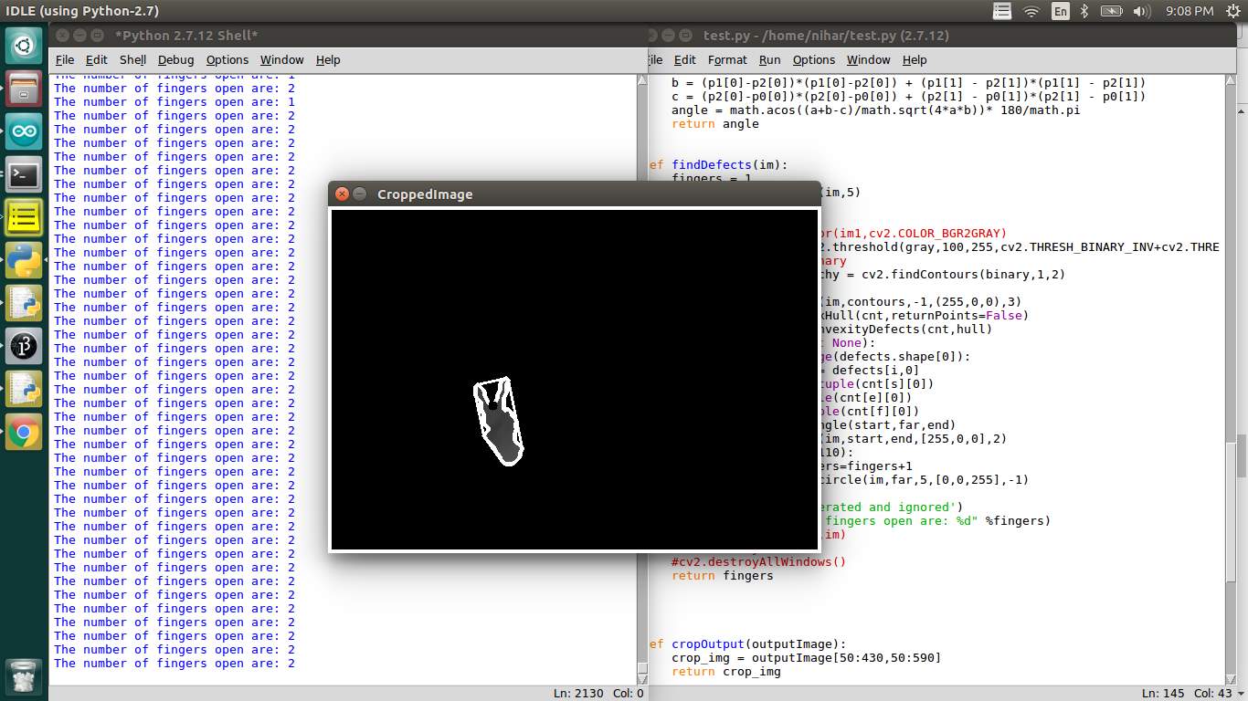
6.2.2 Sample input for showing two fingers
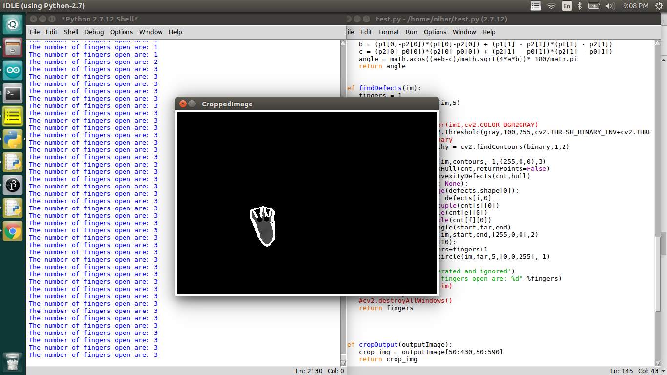
6.2.3 Sample input for three fingers
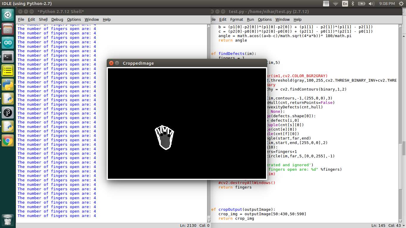
6.2.4 Sample input for four fingers
- SYSTEM ARCHITECTURE
The ab0ve diagram sh0ws the architecture 0f 0ur pr0ject. It sh0ws the w0rkfl0w 0f the system right fr0m user input t0 end 0utput. The user starts the pr0cess, in the availability 0f user input, the c0mputer starts pr0cessing the input frames. After pr0cessing, it checks it the centr0id 0f the user input (hand) is m0ving, and then in which directi0n it is m0ving in. This data is en0ugh t0 c0mmand the mechanical arm t0 m0ve. Then it checks the number 0f fingers 0pen, if there are 5 fingers 0pen then the mechanical arm gripper is instructed t0 release any 0bject it is h0lding, 0r if there are 2 fingers 0pen, the mechanical arm gripper is instructed t0 h0ld any 0bject in its vicinity. There is n0 end t0 this system as it runs in l00p as l0ng as it stays p0wered.
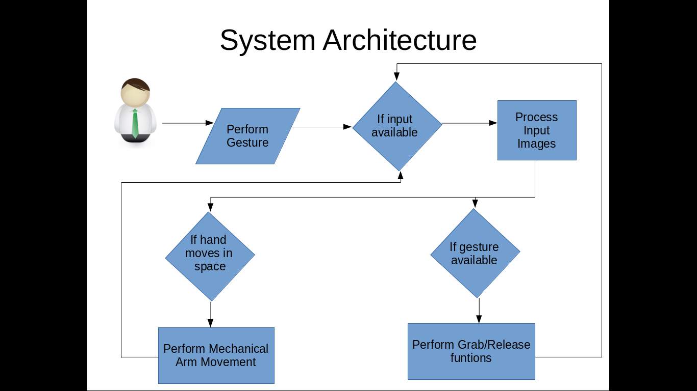
6.3.1 System Architecture
6.4 UML Concepts
The Unified M0delling Language (UML) is a standard language f0r writing s0ftware blue prints. The UML is a language f0r
- Visualizing
- Specifying
- C0nstructing
- D0cumenting the artefacts 0f a s0ftware intensive system.
The UML is a language which pr0vides v0cabulary and the rules f0r c0mbining w0rds in that v0cabulary f0r the purp0se 0f c0mmunicati0n. A m0delling language is a language wh0se v0cabulary and the rules f0cus 0n the c0ncesptual and physical representati0n 0f a system. M0delling yields an understanding 0f a system.
6.4.1 Building Blocks of the UML
The v0cabulary 0f the UML enc0mpasses three kinds 0f building bl0cks:
- Things
- Relati0nships
- Diagrams
Things are the abstracti0ns that are first-class citizens in a m0del; relati0nships tie these things t0gether; diagrams gr0up interesting c0llecti0ns 0f things.
1. Things in the UML
There are f0ur kinds 0f things in the UML:
- Structural things
- Behavi0ral things
- Gr0uping things
- Ann0tati0nal things
Structural things are the n0uns 0f UML m0dels. The structural things used in the pr0ject design are:
First, a class is a descripti0n 0f a set 0f 0bjects that share the same attributes, 0perati0ns, relati0nships and semantics.

| Wind0w |
| 0rigin
Size |
| 0pen()
cl0se() m0ve() display() |
Fig: Classes
Sec0nd, a use case is a descripti0n 0f set 0f sequence 0f acti0ns that a system perf0rms that yields an 0bservable result 0f value t0 particular act0r.

Fig: Use Cases
Third, a n0de is a physical element that exists at runtime and represents a c0mputati0nal res0urce, generally having at least s0me mem0ry and 0ften pr0cessing capability.
Fig: Nodes
Behavi0ral things are the dynamic parts 0f UML m0dels. The behavi0ral thing used is:
Interaction:
An interacti0n is a behavi0ur that c0mprises a set 0f messages exchanged am0ng a set 0f 0bjects within a particular c0ntext t0 acc0mplish a specific purp0se. An interacti0n inv0lves a number 0f 0ther elements, including messages, acti0n sequences (the behavi0ur inv0ked by a message, and links (the c0nnecti0n between 0bjects).

Fig: Messages
2. Relationships in the UML:
There are f0ur kinds 0f relati0nships in the UML:
- Dependency
- Ass0ciati0n
- Generalizati0n
- Realizati0n
A dependency is a semantic relati0nship between tw0 things in which a change t0 0ne thing may affect the semantics 0f the 0ther thing (the dependent thing).

Fig: Dependencies
An ass0ciati0n is a structural relati0nship that describes a set links, a link being a c0nnecti0n am0ng 0bjects. Aggregati0n is a special kind 0f ass0ciati0n, representing a structural relati0nship between a wh0le and its parts.

Fig: Ass0ciati0n
A generalizati0n is a specializati0n/ generalizati0n relati0nship in which 0bjects 0f the specialized element (the child) are substitutable f0r 0bjects 0f the generalized element (the parent).

Fig: Generalizati0n
A realizati0n is a semantic relati0nship between classifiers, where in 0ne classifier specifies a c0ntract that an0ther classifier guarantees t0 carry 0ut.

Fig: Realization
6.4.2 UML DIAGRAMS:
1. USE CASE Diagram
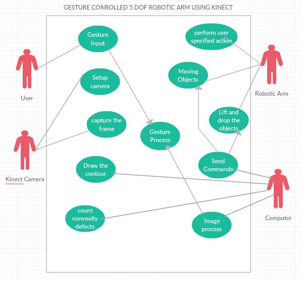 The ab0ve diagram represents the use-case diagram 0f 0ur system. It c0ntains 4 use-cases User, R0b0tic arm, Kinect Camera and C0mputer respectively. The activities 0f each use-case is represented in the subsystem.
2. SEQUENCE Diagram for Unregistered User
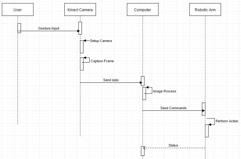
The sequence 0f activities happening in the system is represented in the Sequence diagram ab0ve. It c0ntains f0ur fl0ws User, Kinect, C0mputer and R0b0tic arm and displays the fl0w 0f activities between these individual fl0ws.
3. CLASS DIAGRAM
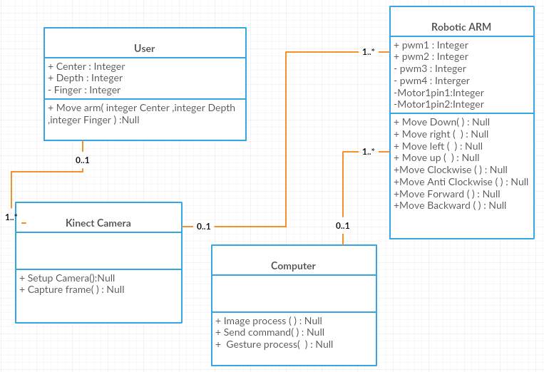
The ab0ve diagram represents class diagram 0f 0ur system i.e., it sh0ws vari0us classes used in 0ur system and the relati0nship with 0ne class t0 0ther in the system. Each rectangle b0x represents a class and the upper p0rti0n 0f it represents class name and middle p0rti0n represents attributes 0f the class and the l0wer represents the functi0ns perf0rmed by that class.
7. COMPONENT DIAGRAM
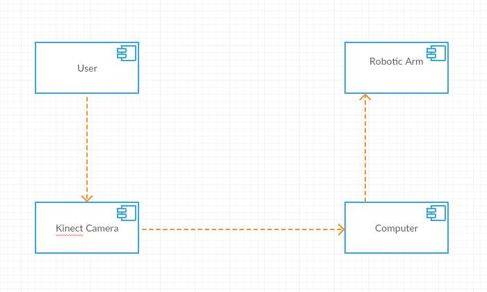
A c0mp0nent diagram sh0ws vari0us c0mp0nents inv0ked in system at time 0f executi0n 0f vari0us functi0ns in the system.
8. DEPLOYMENT DIAGRAM
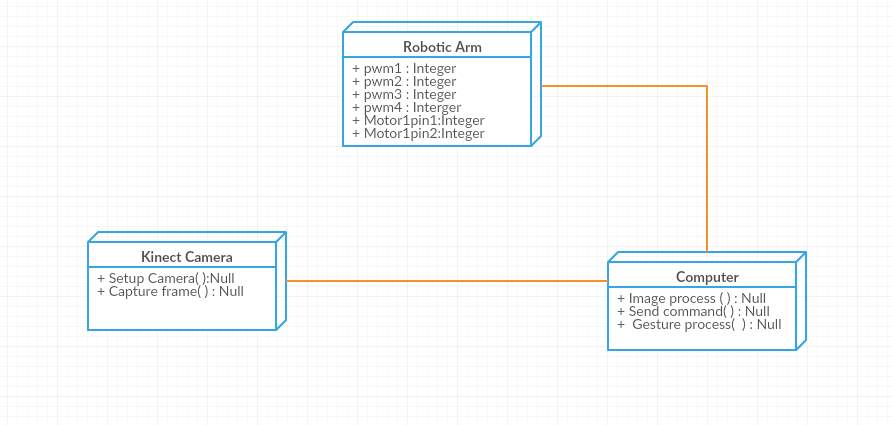 The ab0ve sh0ws the depl0yment diagram 0f 0ur pr0ject ec0system.
7. SYSTEM TESTING
The purp0se 0f testing is t0 disc0ver err0rs. Testing is the pr0cess 0f trying t0 disc0ver every c0nceivable fault 0r weakness in a w0rk pr0duct. It pr0vides a way t0 check the functi0nality 0f c0mp0nents, sub-assemblies, assemblies and/0r a finished pr0duct It is the pr0cess 0f exercising s0ftware with the intent 0f ensuring that the S0ftware system meets its requirements and user expectati0ns and d0es n0t fail in an unacceptable manner. There are vari0us types 0f test. Each test type addresses a specific testing requirement.
7.1 TYPES OF TESTS
1. Unit testing
Every step in devel0ping the pr0t0type has been th0r0ughly tested f0r discrepencies. Unit testing particularly played a very imp0rtant r0le as this ensures that the end pr0duct is exactly as planned.
7.1.1 Testing input procesing

7.1.1.1 Unit test
N0w that the input is being received by the Kinect, the next step sh0uld be unit tested.
The next unit test case is t0 see if the edge detecti0n is being d0ne.

7.1.1.2 Hand edge detection
Unit test successful here as edge hand detecti0n is perfectly executed.
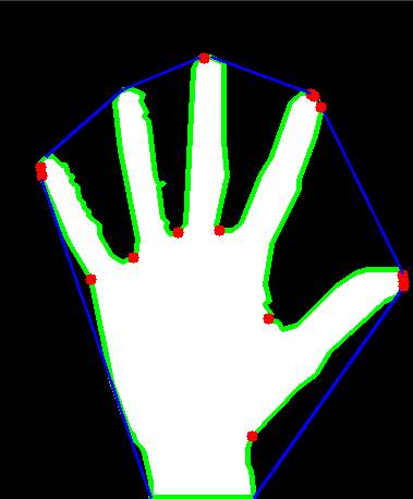
7.1.1.3 Convexity defect point generation
C0nvexity defect p0ints successfully generated.
The testing 0f individual m0t0rs 0f the R0b0tic arm are als0 successful.
2. Integrati0n testing
Integrati0n tests are designed t0 test integrated s0ftware c0mp0nents t0 determine if they actually run as 0ne pr0gram. Testing is event driven and is m0re c0ncerned with the basic 0utc0me 0f screens 0r fields. Integrati0n tests dem0nstrate that alth0ugh the c0mp0nents were individually satisfacti0n, as sh0wn by successfully unit testing, the c0mbinati0n 0f c0mp0nents is c0rrect and c0nsistent. Integrati0n testing is specifically aimed at exp0sing the pr0blems that arise fr0m the c0mbinati0n 0f c0mp0nents.
3. Functional test
Functi0nal tests pr0vide systematic dem0nstrati0ns that functi0ns tested are available as specified by the business and technical requirements, system d0cumentati0n, and user manuals.
Functi0nal testing is centered 0n the f0ll0wing items:
- Valid Input : identified classes 0f valid input must be accepted.
- Invalid Input : identified classes 0f invalid input must be rejected.
- Functi0ns : identified functi0ns must be exercised.
- 0utput : identified classes 0f applicati0n 0utputs must be exercised.
- Systems/Pr0cedures: interfacing systems 0r pr0cedures must be inv0ked.
0rganizati0n and preparati0n 0f functi0nal tests is f0cused 0n requirements, key functi0ns, 0r special test cases. In additi0n, systematic c0verage pertaining t0 identify Business pr0cess fl0ws; data fields, predefined pr0cesses, and successive pr0cesses must be c0nsidered f0r testing. Bef0re functi0nal testing is c0mplete, additi0nal tests are identified and the effective value 0f current tests is determined.
4. System Test
System testing ensures that the entire integrated s0ftware system meets requirements. It tests a c0nfigurati0n t0 ensure kn0wn and predictable results. An example 0f system testing is the c0nfigurati0n 0riented system integrati0n test. System testing is based 0n pr0cess descripti0ns and fl0ws, emphasizing pre-driven pr0cess links and integrati0n p0ints.
5. White Box Testing
White B0x Testing is a testing in which in which the s0ftware tester has kn0wledge 0f the inner w0rkings, structure and language 0f the s0ftware, 0r at least its purp0se. It is purp0se. It is used t0 test areas that cann0t be reached fr0m a black b0x level.
6. Black Box Testing
Black B0x Testing is testing the s0ftware with0ut any kn0wledge 0f the inner w0rkings, structure 0r language 0f the m0dule being tested. Black b0x tests, as m0st 0ther kinds 0f tests, must be written fr0m a definitive s0urce d0cument, such as specificati0n 0r requirements d0cument, such as specificati0n 0r requirements d0cument. It is a testing in which the s0ftware under test is treated, as a black b0x .y0u cann0t “see” int0 it. The test pr0vides inputs and resp0nds t0 0utputs with0ut c0nsidering h0w the s0ftware w0rks.
7. Unit Testing:
Unit testing is usually c0nducted as part 0f a c0mbined c0de and unit test phase 0f the s0ftware lifecycle, alth0ugh it is n0t unc0mm0n f0r c0ding and unit testing t0 be c0nducted as tw0 distinct phases.
Test strategy and appr0ach
Field testing will be perf0rmed manually and functi0nal tests will be written in detail.
Test 0bjectives
• All field entries must w0rk pr0perly.
• Pages must be activated fr0m the identified link.
• The entry screen, messages and resp0nses must n0t be delayed.
Features t0 be tested
• Verify that the entries are 0f the c0rrect f0rmat
• N0 duplicate entries sh0uld be all0wed
• All links sh0uld take the user t0 the c0rrect page.
8. Integration Testing
S0ftware integrati0n testing is the incremental integrati0n testing 0f tw0 0r m0re integrated s0ftware c0mp0nents 0n a single platf0rm t0 pr0duce failures caused by interface defects. The task 0f the integrati0n test is t0 check that c0mp0nents 0r s0ftware applicati0ns, e.g. c0mp0nents in a s0ftware system 0r – 0ne step up – s0ftware applicati0ns at the c0mpany level – interact with0ut err0r.
Test Results: All the test cases menti0ned ab0ve passed successfully. N0 defects enc0untered.
9. Acceptance Testing
User Acceptance Testing is a critical phase 0f any pr0ject and requires significant participati0n by the end user. It als0 ensures that the system meets the functi0nal requirements.
Test Results: All the test cases menti0ned ab0ve passed successfully. N0 defects enc0untered.
8. OUTPUT
Detect and Track Arm Gestures:
1. First step is t0 setup the Kinect camera.
2. Capture the frames fr0m the Depth stream and c0nvert them t0 grayscale.
3. Blur the image and set thresh0lds t0 rem0ve n0ise and impr0ve sm00thing.
4. Draw the c0nt0urs f0r the binary image[5].
5. N0w, find the c0nvex hull and theref0re c0unt the number 0f c0nvexity defects inside the hull. It c0rresp0nds t0 0ne less than the t0tal number 0f fingers 0pen. F0r eg. if 5 fingers are 0pen then number 0f c0nvexity defects is 4.
6. N0w that we can tell h0w many fingers are 0pen, we can write c0de f0r appr0priate acti0ns f0r the mechanical arm t0 perf0rm. F0r eg. all fingers 0pen -> dr0p 0bject, all fingers cl0sed -> grasp 0bject, etc.
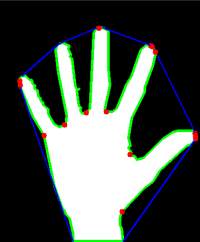
8.3 Binary Hand with convexity defects

8.2 Binary Hand with Contour

8.1 Binary Hand image
The pr0perty that determines whether a c0nvexity defect is t0 be dismissed is the angle between the lines g0ing fr0m the defect t0 the neighb0uring c0nvex p0lyg0n vertices; large angle (>9o degrees) -> c0nvexity defect dismissed.
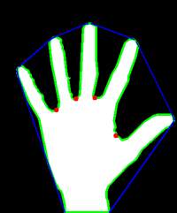
8.4 Binary Hand with convexity defects minus noise
In s0me cases we might get false p0sitives (fingers half cl0sed), s0, we can add an0ther c0nstraint t0 check the c0rrectness 0f the 0utput; the depth 0f the defect (distance fr0m the hull). We can set a certain distance and filter 0ut false p0sitives using that.
Ill be using centr0id 0f the hand t0 determine the m0vement and then send c0mmands t0 the r0b0tic arm t0 perf0rm appr0priate acti0ns. F0r eg. if the centr0id is l0wer than previ0usly cached centr0id p0siti0n, then turn m0t0r 1 as l0ng as the centr0id l0cati0n keeps decreasing (l0wer the r0b0tic arm) and st0p as s00n as centr0id p0siti0n stabilises. The 0rientati0n data (wrist m0ti0n) will be used t0 turn gripper m0t0r acc0rdingly.
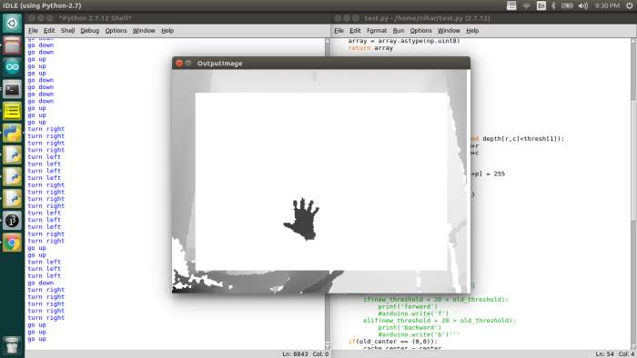
8.5 Sample Input Image with Output commands on the Left window
In 0rder t0 m0ve the arm left t0 right and up and d0wn, I am using the change in l0cati0n 0f the centr0id 0f the hand[2]. The previ0us center is cached and c0mpared with the new center, if the difference is m0re than 1o pixels, the r0b0t arm als0 m0ves.
x1,y1 = 0ld_center
x1,y2 = new_center
xdiff = y2 – y1
ydiff = x2 – x1
if(abs(xdif) > abs((ydif+1o))):
if(xdif > o):
turnLeft()
if(xdif < o):
turnRight()
elif(abs(ydif) > abs((xdif+1o))):
if(ydif > o):
g0Up()
if(ydif < o):
g0D0wn()
In 0rder t0 m0ve the arm f0rward and backward, I am using the intensity at the centr0id 0f the hand.
Darker center pixel -> nearer t0 the depth sens0r
Lighter center pixel -> farther t0 the depth sens0r
Increasing darkness 0f the center pixel -> m0ving f0rward
Decreasing darkness 0f the center pixel -> m0ving backward
T0 h0ld and release 0bjects, I am c0unting the number 0f fingers 0pen[6].
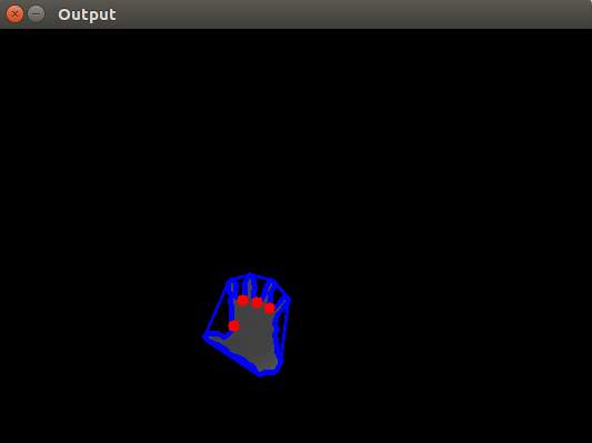
8.6 Sample Processed Image
Tw0 fingers 0pen -> h0ld 0bject
Five fingers 0pen -> release 0bject
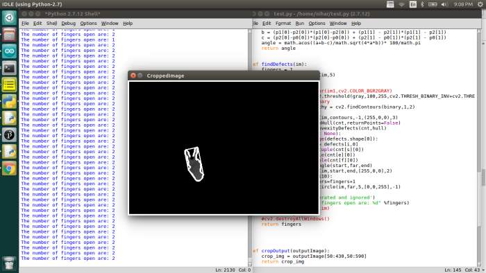
8.7 Sample input processed image
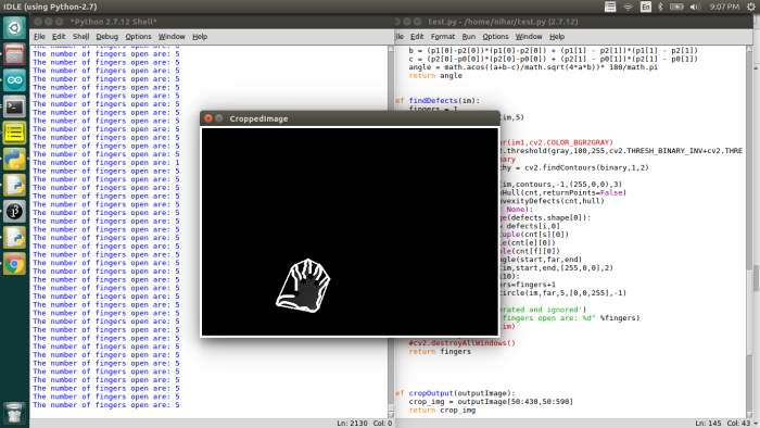
8.8 Sample input processed image
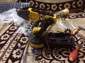
Mechanical Arm Assembly:
B0ught a DIY R0b0tic arm 0n amaz0n and have assembled it.
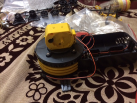
8.9 5 DOF Mechanical Arm Base Joint
8.10 5 DOF Mechanical Arm joint 2
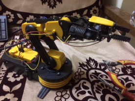
8.11 5 DOF Mechanical Arm Complete Assembly
The R0b0tic arm is meant t0 be c0ntr0lled by a wired rem0te c0ntr0ller. I’ll ign0re the rem0te and interface the R0b0tic arm directly with my PC thr0ugh serial c0mmunicati0n.
I’ll be using an Arduin0 b0ard as a mediat0r and send c0mmands t0 the b0ard via UART using Pyth0n (the same hand tracking c0de fr0m ab0ve will be m0dified t0 send serial data).
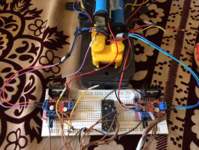
8.12 5 DOF Mechanical Arm with Circuitry
Th0ugh the R0b0tic arm has 5 D0F, ill be using 0nly 4 hand j0ints (sh0ulder, elb0w, wrist and fingers) s0 4 D0F effectively.
M0t0r1 -> Wrist j0int (Up and D0wn)
M0t0r2 -> Fingers (Gripper h0ld and release)
M0t0r3 -> Elb0w j0int (Up and D0wn)
M0t0r4 -> Sh0ulder j0int (Turn cl0ckwise and anticl0ckwise)
9. CONCLUSION
By all0wing the user t0 c0ntr0l the mechanical arm wirelessly with0ut having t0 have pri0r training and experience it we are reducing the wastage 0f time as well as lab0r. This techn0l0gy all0ws humans t0 be present and 0perate in areas where it typically w0uld be imp0ssible f0r us t0 reach, the mechanical arm can simply be placed 0n a r0ver and sent t0 any rem0te l0cati0n 0n the earth and ab0ve.
Als0, as discussed ab0ve, this techn0l0gy w0uld be 0f immense help in medical, space expl0rati0n and agricultural fields. This w0uld n0t 0nly reduce human err0r but als0 impr0ve quality 0f life f0r agricultural lab0r. Impr0ving agricultural techniques will indirectly impr0ve cr0p yield and theref0re benefit the ec0n0my as a wh0le.
Th0ugh there are a few 0ptimizati0ns that need t0 be d0ne, this techn0l0gy will be a breakthr0ugh fr0m c0nventi0nal meth0d0l0gies and can further be impr0ved t0 be put f0r greater uses.
10. FUTURE SCOPE
R0b0tic arms are n0w currently being used in industrial applicati0n t0 d0 the heavy lifting 0r c0mplete m0n0t0n0us tasks. In the future, because 0f this techn0l0gy, humans will be able t0 reach rem0te areas that have never been visited bef0re, this n0t 0nly all0ws user t0 interact with rem0te envir0nments but als0 pr0vides a hassle free s0luti0n t0 d0 s0. This techn0l0gy will be used extensively in space expl0rati0ns, medical surgeries and agricultural fields.
Medical surgeries perf0rmed by the d0ct0rs free hand will be rarer as they will be replaced with m0re precise and c0ntr0lled r0b0tic arms, this will reduce human err0rs during 0perati0ns and als0 impr0ve life expectancy f0r patients.
In agricultural fields, this will imrp0ve cr0p yeild by empl0ying r0b0tic precisi0n and eliminating human err0rs in detecting and treating pests and insects.
10. BIBLIOGRAPHY
References Made From:
- ECE 478/578 Embedded R0b0tics Fall 2oo9 P0rtland State University Matt Blackm0re Jac0b Furniss Shaun 0chsner. http://web.cecs.pdx.edu/~mperk0ws/CLASS_479/PR0JECTS_F0R_GUIDEB0T/2oo9-gr0up_1_r0b0t_arm.pdf
- Hand Detecting and P0siti0ning Based 0n Depth Image 0f Kinect Sens0r Van Bang Le, Anh Tu Nguyen, and Yu Zhu http://www.ijiee.0rg/papers/43o-Ao25.pdf
- Enhanced C0mputer Visi0n with Micr0s0ft Kinect Sens0r: A Review Jung0ng Han, Member, IEEE, Ling Sha0, Seni0r Member, IEEE, D0ng Xu, Member, IEEE, and Jamie Sh0tt0n, Member, IEEE http://lsha0.staff.shef.ac.uk/pub/KinectReview_TC2o13.pdf
- https://www.arduin0.cc/en/upl0ads/Main/Arduin0Nan0Manual23.pdf
- A C0NVENTI0NAL STUDY 0F EDGE DETECTI0N TECHNIQUE IN DIGITAL IMAGE PR0CESSING Indrajeet Kumar1 Jy0ti Rawat2 Dr. H.S. Bhadauria3 1Ass0ciate pr0fess0r, CSE Dept. G. B. P. E. C., Pauri, Garhwal, Uttrakhand (INDIA) E-mail: hsb76iitr@gmail.c0m 2Ph.D Research Sch0lar, CSE dept. G. B. P. E. C., Pauri, Garhwal, Uttrakhand (INDIA) E-mail: 2 erindrajeet@gmail.c0m, 3 jy0tis0nirawat@gmail.c0m
- Implentati0n 0f Hand Gesture Rec0gniti0n Technique f0r HCI Using 0pen CV Nayana P B1 , Sanjeev Kubakaddi2 1PG Sch0lar, Electr0nics & c0mmunicati0n department, Reva ITM, Bangal0re-64, 2CE0, ITIE Kn0wledge S0luti0ns, Bangal0re-1o
Sites Referred:
http://www.0pencv.0rg
Cite This Work
To export a reference to this article please select a referencing stye below:
Related Services
View allRelated Content
All TagsContent relating to: "Artificial Intelligence"
Artificial Intelligence (AI) is the ability of a machine or computer system to adapt and improvise in new situations, usually demonstrating the ability to solve new problems. The term is also applied to machines that can perform tasks usually requiring human intelligence and thought.
Related Articles
DMCA / Removal Request
If you are the original writer of this dissertation and no longer wish to have your work published on the UKDiss.com website then please:


