Landfill Leachate Characteristics and Liner System Effectiveness
Info: 8622 words (34 pages) Dissertation
Published: 15th Dec 2021
Tagged: ConstructionEngineeringMechanics
Abstract
Landfills are the cheapest and most cost effective way of managing waste, however, seepage of the leachates they generate can be detrimental to the environment. Thus, the best way to combat leachate seepage is an efficient landfill liner. This paper will provide a review of leachate characteristics, the various components used in a liner, the different liner systems configurations and the processes used to ensure the effectiveness of these liner systems. Liner systems are highly complex yet efficient systems and can vary greatly depending on the given situation. They are an essential aspect of a landfill due to the variety of benefits they provide however knowing their limitations can allow for the efficient and effective use of them.
Keywords: Landfill liner, Leachate control, Seepage, Geomembrane, Clay Liner
Highlights
- Leachate seepage occurs through two methods, both of which liners must be designed to combat.
- A landfill liner is comprised of multiple components (impermeable layer, low permeable layer, leachate collection system).
- The more layers in a liner system to more efficient and effective it can be in containing leachate.
- Effective construction, planning, and monitoring further ensures liner effectiveness.
Abbreviations
MSW – Municipal Solid Waste
HDPE – High-density polyethylene
CCL – Compacted Clay Liner
BES – Bentonite Enhanced Soils
GCL – Geosynthetic Clay Liners
LCS – Leachate Collection System
QA/QC – Quality Assurance/Quality Control
1 Introduction
The disposal of MSW is a global concern in all countries, whether developed or not, as it is the cheapest and most cost-effective method for waste disposal (Odeoludunks et al., 2011) (Warith, 2003). When MSW is placed into landfills it is subjected to percolation of water due to precipitation or groundwater underflow. As the water percolates through the waste a variety of inorganic and organic compounds are picked up, this contaminated water is what is known are “leachate”. Leachate can include a variety of compounds depending on the given landfill composition, age, waste depth as well as several factors; overall the compounds in leachate are known to be hazardous (Odeoludunks et al., 2011).
In a landfill, the leachate will accumulate at the bottom of the landfill and can seep into the ground water causing contamination unless a barrier or landfill liner system used to prevent this seepage (Daniel & Koerner, 1991). The design of landfill liners is to isolate leachate and other landfill contents from the environment, thus protecting the groundwater and soil from contamination (Sankar & Niranjan, 2015). Landfill bottom liner systems include several components, these components can include a low permeable soil (i.e. clay) layer, a composite material (i.e. geomembranes), and a LCS (Chai & Miura, 2002). With landfill liners becoming increasing more important it is useful to fully understand what the current practice is for liners. Thus, this paper will focus on providing an understanding of landfill liners, how they work and why.
The paper will firstly, provide knowledge on the understanding of landfill leachate and its transportation abilities. Secondly, it will provide an understanding of the with the components used in a landfill liner system and their specific properties. Thirdly, the liner systems themselves will be explained and evaluated on how effective/efficient they are at containing leachate. Lastly, insight into the construction, maintenance, and monitoring of liners will be provided, as these areas further ensure the effectiveness on the liner throughout the landfill’s life.
2 Leachate
The landfill liner is designed to control seepage of leachate so nothing seeps into the ground water. For a liner to perform its duties of retaining leachate it must first be designed from understanding the characteristics of a leachate. This will include the understanding of what a leachate is, how it is generated, how they are transported in landfills, and how to control leachate transportation.
A leachate can be defined as an aqueous effluent generated from waste material. Leachate can be generated due to the percolation of water from waste material (whether it be due to rain, snowmelt or even leachate recirculation). It is due to the biochemical processes within the waste, or from the innate water content within the waste itself (Renou et al., 2008). The composition of the leachate can include organic compounds, inorganic compounds, or heavy metals; the specific composition itself can vary depending on the type of waste the landfill contains and the degradation phase the landfill is currently undergoing (Zhan et al., 2009). Thus, it is this varied yet toxic composition which makes seepage of such concern to ensure and that it does not cause contamination outside the landfill.
The original landfill designs were for dry waste so minimizing leachate generation was a focus. However, new landfill designs (bioreactors) focus on the generation and recirculation of leachate to increase gas generation requiring highly effective liners, fortunately, the recirculation also has the potential to reduce the leachate concentration through dilution or anaerobic reactions within the landfill itself (El-Fadel et al., 2010). Further discussion of this topic, however, is beyond the scope of this paper.
Leachate transportation is an essential component to liner design as a liner should be designed to hold the leachate for the full life of the landfill. This includes both the operational lifetime as well as the post-closure period. The transportation of a leachate depends on the leachate’s hydraulic head, the contaminant concentration in the leachate, the barrier thickness, and the barrier performance (Zhan et al., 2009). For a liner, the transportation of a leachate can occur through two pathways, diffusion through the liner itself or advection through a defect. Advection through geomembranes and their respective characteristics is further discussed in Section 3.1.
Holes or defects are hard to design against and thus making diffusion the primary transportation process which can be best designed against (Zhan et al., 2009). A diffusion model for a simple liner is shown in Figure 1. Hyun et al. (2011) described these transportation factors while evaluating on the adsorption of fluoride by liner material, they concluded the exact factors, of which the liner thickness is the most critical in controlling the seepage. Beyond experimental results diffusion models or “breakthrough time” models have been developed through numerical modeling as well as.
Chen et al. (2015) developed one of these numerical models which includes several design charts to determine the optimal design thickness of composite liners. Besides controlling the liner thickness other methods for preventing seepage include: controlling the hydraulic head, which is further discussed in Section 3.4 as it is a critical component used in today’s liner systems.
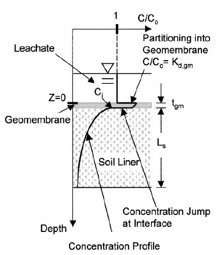
Figure 1: Leachate transportation/diffusion model (Zhan et al., 2009).
To truly prevent the movement and seepage of leachates the best design is developed based on the understanding of leachates themselves, the various contaminants they can contain, and the factors which influence their transportation through a liner. With this understanding, effective liner systems can be utilized in minimizing or eliminating leachate seepage.
3 Liner Components
A landfill liner today is known as a landfill liner system, this is because of the numerous components which are used in combination to act as the liner. Each component used brings its each unique characteristics and properties, which when combined allows for the liner system to have a number of wide range characteristics. Depending on the liner system’s design they can contain various components, however, the most common types of components are a geosynthetic layer, a low permeability layer, and a LCS. All the components are used to reduce the risk of seepage whether it be through stopping or minimizing the seepage rate of the leachate to reducing the hydraulic head and actually removing the leachate. Although each component has several advantages they also come with a few disadvantages, it is important to understand and know what these are so one can better understand a liner system, and how to best mitigate the chance of leachate seepage.
3.1 Geosynthetics
In a landfill liner, the thinnest yet most impermeable layers are the geosynthetic layer(s). A geosynthetic is a fabric-like material that is made from petroleum by-products such as polyethylene, polyester, and polyvinyl chloride (Das, 2009). Through the manufacturing process these materials although thin are impermeable, able to withstand mechanical stresses/strain, and are compatible with various chemicals in a landfill leachate (U.S. Environmental Protection Agency, 2000). Geosynthetic materials have been used since the 1980s because of the unique features they possess, whether that be their high hydraulic conductivity, small pore size or their almost negligible hydraulic conductivity, all of which make them useful for various aspects of a landfill liner (Das, 2009).
Common geosynthetics used in landfill liners include geotextiles and geomembranes. Geotextiles are like traditional textiles and can be woven, knitted or nonwoven because they are like a traditional textile. They have a relatively high hydraulic conductivity which allows liquids to pass through them. Their most common use is in LCSs as the filter layer to prevent slimes from entering the drainage area; this topic is further discussed in Section 3.4. Generally, they are used to separate soil types, provide filtration for drainage areas or provide tensile strength to the soil. Geomembranes, on the other hand, are impermeable barriers that are made from continuous polymeric sheets and are quite flexible (Das, 2009).
One of the most common types of geomembranes is a HDPE, this is because HDPEs are highly chemical resistant compared to other options (Brachman, et al., 2007). Since geomembranes are used in combination with low permeable materials a main feature of them is to prevent seepage of ionic compounds such as chlorine which through ion exchange can seriously alter the structure of the low permeable materials (Rowe et al., 2003). Geomembranes, although stated, are impermeable are actually not, they have been shown to allow permeation at rates of 10-10 to 10-13 cm/sec, which makes them essentially impermeable (Das, 2009).
However, due to their thin nature geomembranes are prone to punctures, even with careful installation and stringent construction quality control it is assumed that a geomembrane will have 2.5 to 5 holes per hectare (Brachman, et al., 2007). Thus, seepage is most common through these holes and why low permeable layers are used underneath geomembranes in a landfill liner.
3.2 Low Impermeable Barriers
Containing landfill wastes has been something which has been done since the 1970s. When landfill liners were first developed there were no geosynthetic materials, designers turned towards natural impermeable or low impermeable materials. These materials had very low hydraulic conductivities which ensured that seepage through this material would take a long time. These materials have also been shown to adsorb significantly large volumes of water as well to essentially “trap” it, as another way to reduce seepage (O'Sullivan & Quigley, 2017).
In the past and in the present this material is most commonly clay, the exact characteristics of the clay can vary significantly. Currently, these clay liners or CCLs are used under a geomembrane material to adsorb and significantly slow the seepage of leachates (Katsumi et al., 2001). The use of CCLs is quite common and their properties should be known, the low permeability slows seepage of leachates but their ability to crack due to ion exchange and desiccation can greatly increase their hydraulic conductivity if they are exposed to certain conditions or contaminants. There are also alternative materials which can be used to replace this CCL.
Overall the materials used as a low-permeable barrier all are designed to further reduce the seepage of a leachate. These low impermeable layers are classified by a few factors; these factors are their hydraulic conductivity, compaction, saturation, and thickness. The hydraulic conductivity is a function of the porous material and of the fluid passing through, its typical units are m/yr or cm/sec. From the units it is evident that the hydraulic conductivity refers to how fast the fluid can flow through the material, this property is essential in calculating a landfills breakthrough time. The hydraulic conductivity of a material goes hand in hand with its compaction, as the more compact a material is the lower its respected hydraulic conductivity becomes (O'Sullivan & Quigley, 2017). Hence why clay liners are commonly referred to as CCLs as they are compacted to an optimum value when placed.
Next is the CCLs saturation, the saturation of a CCL is related to both its compaction and shear strength. The optimal compaction percentage is a function the materials saturation level, while the CCL shear strength is used in providing stability to the landfill. If the liner is not strong enough it could lead to a slope failure. This failure could ruin the liner’s integrity and cause significant leachate seepage (Jones & Dixon, 2003). Shear strength of a CCL is only noted as it is related to ensuring the geotechnical strength of the liner itself, further discussion on CCLs stability is beyond the scope of this paper.
Lastly, the liner thickness ties all the other factors together as its thickness is based on stability but more so retaining leachate and prolonging its breakthrough time. As clay is a natural material its properties can vary, thus by defining the CCL by several properties it ensures the quality of each CCL and ensures it will be an effective barrier. When CCLs are in direct contact with the leachate there are two points which are to be noted.
Firstly, is the adsorptive property present, the adsorption varies depending on the type of clay. Bentonite is proven to be the best clay as it can adsorb significant amounts of liquid and is known to swell considerably (Lu et al., 2011).
Secondly is how clay can crack due to ion exchange or desiccation. Since clays have charged particles an interaction with charged molecules can lead to an ion exchange, with the ion exchange there is a deterioration of the clay structure which causes cracking (Bouazza, 2002).
Cracking is also caused by desiccation or extreme drying if the clay is not exposed to any water over a long period of time. This cracking is extremely detrimental as it can cause an increase in hydraulic conductivity by up to 500 times, which essentially allows leachates to freely flow through the layer (Safari et al., 2014). Thus, it is very important to know that although CCLs are effective they are also quite susceptible to damage. Although clays are the most common low permeable barriers used there are not the only option available as research has been done on assessing the applicability of other materials, the most notable of these materials are fly ash, sepiolite, and asphalt.
Fly ash is a by-product of coal burning for power generation thus there is a lot of this material readily available. When combined with lime and bentonite fly ash has shown hydraulic hardening, like in cement. Not only have fly ash mixtures show to reach the desired hydraulic conductivity they have shown the ability to resist cracking and the potential to be an effective chemical barrier (Chakradhar & Katoch, 2016) (Nhan et al., 1996). Fly ash can act as a chemical barrier due to the hydroxides and carbonates in the fly ash which control the pH of leachate and cause metals to precipitate out upon contact (Nhan et al., 1996).
Sepiolite is a type of clay which contains much more magnesium than other clays, they have a unique structure which allows them to trap liquid and absorb up to 250 times their original weight. Although this clay type does not possess a low hydraulic conductivity it does possess a high adsorption factor for inorganic contaminants. Thus, when mixed with a low hydraulic conductivity clay can be a highly effective barrier material (Guney et al., 2008).
Asphalt has actually been used in liner water containment structures for over 60 years as it tends to have a very low hydraulic conductivity (3x10⁻⁹ cm/s), resists cracking and displays the ability to creep which can lead to ‘self-repair’. Also, it has been documented that asphalt has a long service life when buried which is advantageous. The composition is similar to that used on roads however the barrier composition contains a higher content of aggregate fines and 6-9% asphalt, this allows for fewer air voids in the material. Asphalt can be an effective barrier however like clay it is susceptible to organic solvents and should be used in combination with an impermeable barrier as well to be effective (Bowders et al., 2000).
The above are all examples of alternative low-permeable barrier materials which can be used in a Liner system. CCLs have been used as an original landfill liner and are continually being used as a secondary component. Their low hydraulic conductivity and adsorptive ability allows for retaining leachates which have gotten through a geosynthetic liner (O'Sullivan & Quigley, 2017). Unfortunately, their ability to crack through ion exchange or desiccation can lead to a drastic loss in hydraulic conductivity (Bouazza, 2002) (Safari et al., 2014). Other materials such as fly ash, sepiolite and asphalt have shown the ability to replace the CCL as a low-permeable barrier with their own unique features. Overall the use of a CCL in a liner can be beneficial in combatting leachate seepage given the proper conditions.
3.3 Composite Liners
Composite liners are liners or liner materials which contain multiple materials combined. They are a more economical use of liner material and combine the benefits of various materials. The two most common composite liners are bentonite enhanced soils and geosynthetic clay liners. BESs are when bentonite is added to the natural soil while GCLs are a composite mat with a layer of bentonite stitched in between two geosynthetic layers (U.S. Environmental Protection Agency, 2000). BESs are typically used in locations where access to large amounts of low permeable clay is limited. Thus, BES use a small amount of bentonite clay to fill in the voids of the soil, by filling the voids it provides the soil with a lower permeability (O'Sullivan & Quigley, 2017). Due to the small amount of clay present, these barriers are unable to achieve a comparable hydraulic conductivity to CCLs but are still a suitable barrier material (Jones & Dixon, 2003).
As mentioned in Section 3.2, bentonite has remarkable absorbing and swelling capabilities, testing of BESs has shown that after a leachate has passed through the BES the concentration of contaminants below are much lower than that which the BES has absorbed (Kalbe et al., 2002). Unfortunately, there is a range of bentonite clays which have a range of properties so the use of a specific one must be compared with the expected leachate to be produced and differences between the expected and actual leachate can have significant effects on the BESs effectiveness. The best method to ensure the proper bentonite clay is used requires large-scale tests to evaluate the actual performance (O'Sullivan & Quigley, 2017).
GCLs have been increasing in popularity over the past years because they combine the best properties of a CCL and a geomembrane liner. Essentially the geomembrane limits the area in which leakage can occur and the bentonite layer beneath limits any further leakage through the geomembrane through adsorption and its high hydraulic conductivity (Katsumi et al., 2001). The main advantages of GCLs are how this they are, easy installation and low cost. However, their use has been questioned because of their susceptibility to leachate permeation, limited sorption capacity, low attenuation rate and ion exchange (Bouazza, 2002). Since GCLs are created by stitching or fusing two geomembranes liners together the chance of an unprotected puncture is much greater than usual and can cause seepage through the liner faster than expected. Beyond the initial seepage through the geomembrane liner, the bentonite layer present is much thinner than a typical CCL so it has a much lower breakthrough time even with its high hydraulic conductivity (Bouazza, 2002).
Lastly, if the geomembrane is punctured the bentonite clay can undergo ion exchange with either the native soil or the leachate causing a reduction in its hydraulic conductivity and adsorption ability (Touze-Foltz et al., 2006). Composite liners have shown to include the benefits of CCLs and geomembranes while limiting the required material required, something quite advantageous for areas which access to the material may be restricted. However, it is important to realize that with these composite materials there are limitations, which can limit their use or limit their ability to be used without additional liner components.
3.4 Leachate Collection/Control Systems
In Section 2 the characteristics of a leachate and how they move through a liner were described. This includes the factors which influence how leachates are transported. Out of the factors affecting leachate transportation, controlling the hydraulic head is the one focused on as it can greatly reduce the potential for leachate seepage to occur. A LCS is how the leachate itself can be drained, and it is exactly how the leachate hydraulic head is controlled. Standard performance criteria used today for designing LCSs is to have a maximum head of 0.3m and a service life of 100 years. The two main aspects which should be considered for an LCS are the leachate’s hydraulics and the LCS collection/drain design (Gondim et al., 2016). A LCS design is based on the principles of hydraulics.
To model the hydraulics there are three models that can be used, these models are steady state, quasi-steady state, and transient state. Of these models, the steady-state model is used for the general case and assumes zero leakage, while the quasi-steady state and transient models provide more accurate results (Demetracopoulos, 1988). The transient model is usually developed in a FEM software and can provide accurate guidelines for design whereas the quasi-steady state tends to overestimate leakage while underestimating drainage (Korfiatis & Demetracopoulos, 1986).
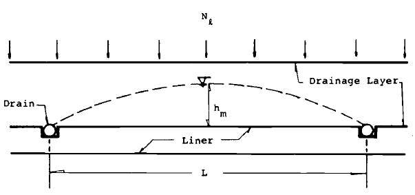
For the purpose of this paper, the steady-state model will be discussed because of the model’s simplicity. Two common steady state LCS configurations are shown in Figure 2, of these two the simplest design is a horizontal LCS which will develop the steady-state hydraulic head mound shown by the dashed line. Although the design allows for the collection of leachate it still allows for a significant hydraulic head to be present between drain pipes, which is undesired. This hydraulic head is combatted by the design shown to the left, this design uses a sloping geometry, this simple addition of the sloping geometry allows for a reduction in the hydraulic head between the collection pipes (Demetracopoulos, 1988). By minimizing the hydraulic head and adding the slope it ensures leachate isn’t stagnant and constantly in contact with the same area of the liner, this constant movement adds additional risk mitigation to leachate seepage.
 |
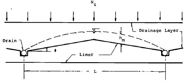 |
Figure 2: LCS systems: (left) horizontal system and (right) sloping system (Demetracopoulos, 1988).
The purpose and intent of a LCS is to control the hydraulic head on the liner. As mentioned above this is conducted by drains embedded in the liner, these drains usually drain to one collective sump (landfill low spot) and are pumped out from there. A typical LCS from the bottom up will include a drainage pipe or medium, a filter separator and a protective layer (U.S. Environmental Protection Agency, 2000). The drain can be either a drain pipe or a drainage blanket.
Pipes are used if there is a considerable amount of leachate or for landfills with a considerably long life as it allows for the LCS to be cleaned out as required. A drainage blanket is a porous material which easily allows the water to flow through, the typical porous material used is gravel over sand as it does not clog easily due to its larger pore size; shredded tire may also be used but if compressed can cause a reduction in porosity and hydraulic conductivity (Gondim et al., 2016).
The filter separator is used to prevent or reduce fines from entering the LCS, geotextiles are commonly used for this. Clogging usually occurs due to the collection of slimes, these slimes are usually generated by an aerobic reaction of the waste material (U.S. Environmental Protection Agency, 2000).
Finally, the protective layer is put on the entire system to reduce the risk of damaging the LCS as waste is added to the landfill, this is especially important in the initial phases of a landfill's life as early damage to the LCS could easily lead to more detrimental effects later on. Material for the protective layer can be similar to those of the drainage layer. Overall one of the largest considerations for choosing material is the local availability of it (Gondim et al., 2016). Beyond the LCS is the location of it, an LCS can be used on the surface of the landfill liner or as a detection layer. By using it on the surface it allows for the direct control of the leachate whereas the use in a detection layer allows for developing an understanding of the leachate seepage rate so the liner performance can be evaluated (U.S. Environmental Protection Agency, 2000).
Further discussion on the two setups will be discussed in Section 4 as part of the liner system. Through the understanding of the hydraulic design concerns and the LCS collection/drainage design the performance are better understood. The higher the leachate’s hydraulic head the higher the likelihood that seepage will occur, thus an efficiently designed liner geometry can minimize the head of the leachate. Clogging can serious disrupt the LCS and to ensure it remains in working order proper materials/design must be used to minimize the build up of slimes. Thus, an understanding of the properties of an LCS allows for its purpose in a liner system to truly be appreciated.
4 Liner Systems
There are numerous components used in a current landfill liner, all of these components have advantages as well as some disadvantages. Given that the main objective of a landfill liner is to contain leachate and stop, the components discussed in Section 3 can not be used alone because of the disadvantages they have. However, the combination of these components allows for a complete liner system as the disadvantage of one component is counteracted by the advantages of another. Liners today vary depending on the type of leachate that the landfill contains, as the more hazardous a leachate is to more intensive of a liner is required (Hughes et al.).
Common liner systems today are a single liner system, a composite liner system (quite similar to a single liner system), and a double liner system. The specific liner system is chosen based on the legislative requirements, and landfill type (U.S. Environmental Protection Agency, 2000). A single liner system has been a standard in landfill design for may decades and has only been improved to as new technologies came about. The single liner system is quite diverse as they originally started out as just a CCL, but some current single liner systems now contain a LCS and/or a geomembrane. A cross section of a single liner system including all three components is shown in Figure 3. Single liners may also be known as a composite liner, this name is given when the liner contains both a geomembrane and a CCL, thus but a “composite” (Hughes et al., 2005).
The thickness and actual requirements in a single liner system will vary depending on the country and the local legislation. Depending on the waste material the LCS may or may not be included in the liner system as well (Bouazza & Van Impe, 1998). Since they only contain the one layer they are not the most efficient at containing leachate and there is no way to determine if any leachate has seeped through. Thus, they are commonly used for non-hazardous biodegradable waste landfills as they are a cheaper system to install (U.S. Environmental Protection Agency, 2000) (Hughes et al., 2005).
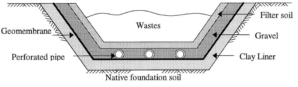
Figure 3: Typical single liner system (Bouazza & Van Impe, 1998).
The more common option for landfill liners today is a double liner system, which essentially is a combination of two single/composite liner systems. Commonly the top layer system is the primary control for resisting leachate seepage or limiting the migration of the leachate. Following the first layer is a leakage detection system which is used to evaluate the first layer to determine if it has lasted its respective breakthrough time, provide a secondary warning so the landfill operator is aware of the seepage distance, and to remove all leachate which has seeped through the first layer. Lastly is the second layer which acts as a backup liner to prevent any further seepage through the liner system (Hughes et al., 2005). A typical cross section of a double liner system is shown in Figure 4.
As mentioned in Section 2, controlling leachate head is important to reduce the chance of seepage, a unique feature about the double liner is the primary and secondary LCS which allows for a double reduction of the hydraulic head so that the hydraulic head present at the top of the second layer would be very low compared to the original head at the liner surface (Daniel & Koerner, 1991). Again, like a single liner system the thickness of each layer as well as the specifications for each vary depending on the country and local legislation (Bouazza & Van Impe, 1998). With laws in many countries becoming stricter with regards to stopping leachate seepage double liner systems are becoming the common choice. The double layer makes them ideal for hazardous waste landfills as well as those which are expected to generate a lot of leachate (Hughes et al., 2005).
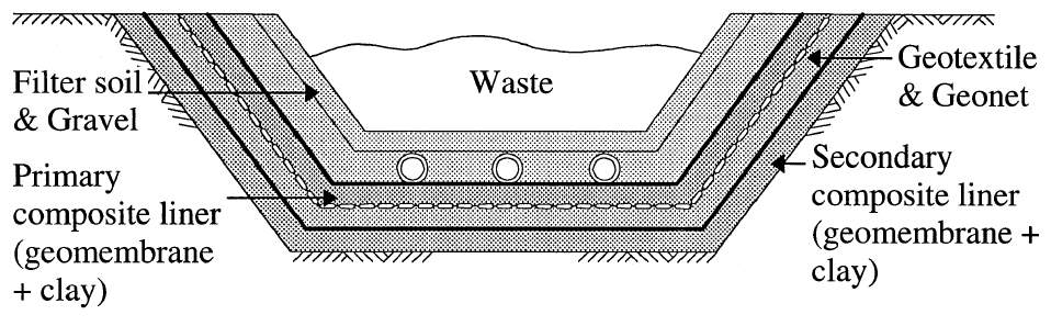
Figure 4: Typical double liner system (Bouazza & Van Impe, 1998).
Liner systems can contain a wide variety of components depending on the design requirements. These liner systems are highly effective at containing leachate and stopping seepage from occurring. Overall the liner systems will provide containment of the leachate, however, the proper system must be chosen to ensure sufficient containment.
5 Construction, Maintenance & Monitoring
Beyond the performance and capabilities of a liner system, there are various aspects which ensure they meet their full potential and track the extent of any possible liner failures. This section will discuss the various features of a landfill’s life which ensure the liner effectiveness. During construction, various steps and procedures can not only provide confirmation of the design specification but also ensure optimal development of the liner. After construction maintenance and monitoring are what not only ensure the liner stays effective but allows for extra protection in case of seepage through the liner does occur.
5.1 Construction
A landfill liner is a complex system which needs to be built and constructed efficiently so it can contain the leachate as designed. There are several steps a landfill will follow to ensure the efficiency of the liner. These steps include conducting a site investigation, constructing the landfill in stages and utilizing a proper QA/QC program for all aspects of construction.
First off is the site investigation, this should be one of the first steps in the designing and construction of a landfill. By conducting a site investigation a number of specific site features can be determined, these features can both dictate design parameters as well as provide further information on various aspects of the design (Government of Alberta, 2010). Specifically, a detailed investigation such as a hydrogeologic investigation should be conducted. This detailed investigation will provide detailed information about the native soil properties, thus allowing for the proper liner system and components to be utilized in the landfill. These properties additionally provide insight into if the native soil will assist in retarding leachate seepage or not (Rowe et al., 2000).
Landfills are large extensive projects, thus they must be built to a significant size to ensure long term use. However, if the entire landfill is construction all at once there is a greater chance of damaging the liner is areas that are left exposed. This is dealt with by developing the landfill is phases, by developing the landfill in phases it allows operation and construction to happen simultaneously (U.S. Environmental Protection Agency, 2000). Furthermore, each phase is divided into cells, these cells are the smaller actual working face of the landfill during operation (Rowe et al., 2000).
Cells are used as their smaller size allows for minimizing the exposure the waste has with the environment and thus minimizes waste leachate generation as each cell is covered after being filled (U.S. Environmental Protection Agency, 2000). A scenario of landfill phasing and the working cell is shown in Figure 5, whereas the left illustration is operation in phase 1 and it progresses to the right illustration after filling phase 1. Overall the use of phases and cells for a landfill allows for optimal operation and construction of the landfill as well as the control of leachate generation within the landfill from the very beginning.
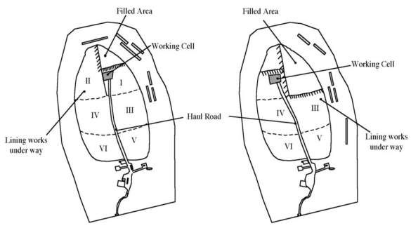
Figure 5: Phase 1 in operation (left) & phase 2 in operation (right) (U.S. Environmental Protection Agency, 2000).
The integrity of each liner component is one of the most important aspects, if the integrity of any of the layers is compromised it can cause premature seepage and possible contamination of the environment. It has been found that in most cases the integrity of any competent is compromised during the construction process as well, thus an effective QA/QC program when implemented will ensure efficient construction as well as ensuring the integrity of the liner components (Daniel & Koerner, 1991).
In terms of the geomembrane liner, their thin design makes them highly susceptible to holes and punctures, to combat this issue a good QA/QC system will include inspections, seam testing, and even the use of an electrical system to evaluate the integrity of the geomembrane to ensure any holes are patched and all seams are truly sealed. By ensuring such an intensive program it can eliminate the potential for holes to be in the geomembrane (Schevon & Damas, 1986) (White & Barker, 1997).
Beyond the geomembrane liner is the CCL, as mentioned in Section 3.2 compaction of the material is related to its hydraulic conductivity. Thus, to ensure the effective hydraulic conductivity is met the liner must be built up in lifts, by being built up in lifts each lift is compacted to the optimal percentage but if the entire layer is just compacted once the upper portion may meet the required compaction but the lower portion will not be as compacted. This can cause a high overall hydraulic conductivity which would result in a lower breakthrough time and potentially premature leachate seepage into the environment.
Ensuring effective compaction becomes even more important with the type of landfill as hazardous waste landfills will construction smaller lifts to develop a lower hydraulic conductivity (Benson etal., 1999). An effective QA/QC system, through testing and inspection, will ensure the integrity of the liner system components and as a whole. Overall there are several aspects to consider during the construction phase of a landfill, each important in ensuring the proper liner design and adequate development of the landfill.
Conducting a thorough and full site investigation allows for a detailed account of the site so an appropriate design can be developed to met the site characteristics (Rowe etal., 2000). The construction of a landfill in phases and cells ensures the minimization of leachate generation as well as allowing simultaneous construction and operation of the site (U.S. Environmental Protection Agency, 2000). Finally, a proper QA/QC system will ensure the full integrity of the liner system as well as ensuring all components were constructed to meet the design specifications (Schevon & Damas, 1986).
5.2 Maintenance
One of the issues with landfill liners is that they must be designed to contain any leachate for the entire lifetime of the landfill. This lifetime includes all the phases of a landfill: the construction phase, operational phase, closure phase and post-closure period. Overall the life of a landfill can be over 30 years, most of which is just the post-closure period where the waste is monitored to ensure it reaches a stabilized state. This is a long period of time of the liner to resist any leachate seepage. Also, if seepage is detected it is quite difficult to reach the leakage area as it requires removal of the waste, which after closure is not feasible since the cover would have to be removed (Morris & Barlaz, 2011).
With regards to the maintenance of the liner there are two steps, firstly is a QA/QC as described in Section 5.1 during construction and the second is through monitoring systems. Once the landfill is operational monitoring systems are used, these systems are further described below in Section 5.3 (Daniel & Koerner, 1991). Unfortunately, due to landfills constantly being filled with waste maintenance is not a feasible task and other strategies are put in place to compensate for it.
5.3 Monitoring
Landfill liners are designed to contain the waste leachate, however monitoring systems are usually implemented to ensure there is no leachate seepage into the groundwater through the landfill’s lifetime. The traditional method for monitoring has been perimeter boreholes but a more accurate method, electrical monitoring systems have also been implemented (Lee & Jones-Lee, 1996) (White & Barker, 1997). The owner of a landfill is responsible for ensuring there is no seepage of leachates, monitoring systems are utilized for this so even after the closure of the landfill if leachates do seep into the groundwater they can be detected. The location of the monitoring points is determined during the site investigation and are spaced hundreds of meters apart. However, this method which is still used was designed based on the assumption that a leachate contaminant will disperse laterally once introduced to the groundwater (Lee & Jones-Lee, 1996).
When a landfill does leak the source is through a hole or tear and dispersion is in a linear fashion like a finger, with this method it makes the monitoring wells incapable of detecting contamination as shown in Figure 6. Thus, there is a low probability that the wells will detect a leak unless the finger like plume intersects with a well (Lee & Jones Lee, 1994). Therefore, a more effective leak detection system would be one which could detect leaks directly in a liner, a system like the electric monitoring system would do just that.
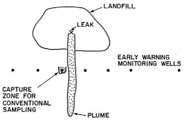
Figure 6: A landfill leakage plume and monitoring system (Lee & Jones Lee, 1994).
The electrical monitoring system was developed as a way of providing better monitoring. An electrical system can be used because the geomembrane is an electrical insulator. The system uses an electrical current which is passed from an electrode plate above the liner to a plate placed below the liner since the liner is an electrical insulator no current can be passed through except through a hole (White & Barker, 1997). These holes can be mapped and pinpointed by the high voltage charge around them. Additionally, if a high-density electrode system is installed below the landfill it can not only evaluate the integrity of the liner but can also track leachate seepage as it permeates through the liner system. Thus, allowing for a remediation operations to take place and minimize the environmental impact the contamination may have (White & Barker, 1997).
6 Conclusion
An effective landfill liner contains the leachate to prevent seepage and contamination. Thus, for the landfill liner to be as efficient as it is required to be it can not have any flaws. Therefore, liners today are quite complex and utilize various aspects of different components to ensure their effectiveness. Even with the complexity of a liner system, the potential for seepage can still be encountered, thus mitigation of seepage is conducted through effective construction and monitoring. Liners are an important aspect of a landfill, however, it is important to understand and realized both their abilities and limitations.
References
[1] A. A. Odeoludunks, O. A. V., A. G. A. and O. A. A., "Assessment of Groundwater Contamination by Leachate near a Municipal Solid Waste Landfill," African Journal of Environmental Science and Technology, pp. 933-940, 2011.
[2] M. Warith, "Solid Waste Management: New Trends in Landfill Design," Emirates Journal of Engineering Research, pp. 61-70, 2003.
[3] D. E. Daniel and R. M. Koerner, "Landfill Liners From Top to Bottom," Civil Engineering Design, pp. 46-50, 1991.
[4] V. Siva Ravi Sankar and D. V. Niranjan, "Effect of Compaction conditions on the Hydraulic and Compressibility Behaviour of Fly Ash - Bentonite mixtures," Journal of Mechanical and Civil Engineering, vol. 12, pp. 1 - 28, 2015.
[5] J.-C. Chai and N. Miura, "Comparing the Performance of Landfill Liner Systems," Journal of Material Cycles Waste Management, pp. 135-142, 2002.
[6] S. Renou, J. Givaudan, S. Poulain, F. Dirassouyan and P. Moulin, "Landfill leachate treatment: review and oppourtunity," Journal of Hazardous Materials, pp. 468-493, 2008.
[7] T. L. T. Zhan, C. Yun-Min and T. Xiao-Wu, "A preliminary understanding on performance of barriers for MSW landfills in southern china," in International Symposium on Geoenvironmental Engineering, Hangzhou, 2009.
[8] M. El-Fadel, A. N. Findikakis and J. O. Leckie, "Modeling Leachate Generation and Transportation in Sold Waste Landfills," Environmental Technology, vol. 18, pp. 669-686, 2010.
[9] S. Hyun, D. H. Kang, J. Kim, M. Kim and D.-Y. Kim, "Adsorptive removal of aqueous flouride by liner minerals from SPL-landfill leachate during the seepage process," Desalination, vol. 276, pp. 347-351, 2011.
[10] Y. Chen, Y. Wang and H. Xie, "Breakthrough time based design of landfill composite liners.," Geotextiles and Geomembranes, vol. 43, pp. 196-206, 2015.
[11] B. M. Das, "Landfill Liners and Geosynthetics," in Principles of Geotechnical Engineering, Thompson Engineering, 2009, pp. 544-557.
[12] U.S. Environmental Protection Agency, "Landfill Manuals Landfill Site Design," Environmental Protection Agency, Ireland, 2000.
[13] R. W. I. Brachman, R. K. Rowe, W. A. Take, D. N. Arnepalli, M. Chappel, L. E. Bostwick and R. Beddoe, "Queen's Composite Geosynthetic Liner Experimental Site," in Ottawa Geotechnical Engineering, Ottawa, 2007.
[14] R. K. Rowe, H. P. Sangam and C. B. Lake, "Evaluation of a HDPE geomembrane after 14 years as a leachate lagoon liner," Canadian Geotechnical Journal, vol. 40, pp. 536 - 550, 2003.
[15] D. O'Sullivan and P. Quigley, "Geotechnical Engineering and Environmental Aspects of Clay Liners for Landfill Projects," Fehily Timoney & Co & Irish Geotechnical Services Ltd., 2017.
[16] T. Katsumi, C. H. Benson, G. J. Foose and M. Kamon, "Performance-based design of landfill liners," Engineering Geology, vol. 60, pp. 139-148, 2001.
[17] D. R. V. Jones and N. Dixon, "Stability of Landfill Lining Systems: Report No. 1 Literature Review," Environmental Agency, Almondsbury, 2003.
[18] H. J. Lu, M. T. Luan and J. L. Zhang, "Study on transport of Cr(VI) through the landfill liner composed of tow-layer soils," Desalination, vol. 266, pp. 87-92, 2011.
[19] A. Bouazza, "Geosynthetic clay liners," Geotextiles and Geomembranes, vol. 20, pp. 3-17, 2002.
[20] E. Safari, M. J. Ghazizade, M. A. Abduli and B. Gatmiri, "Variation of crack intensity factor in three compacted clay liners exposed to annual cycle of atmospheric conditions with and without geotextile cover," Waste Management, vol. 34, pp. 1408 - 1415, 2014.
[21] V. Chakradhar and S. S. Katoch, "Study of Fly Ash in Hydraulic Barriers in Landfills - A Review," in IRF International Conference, Goa, 2016.
[22] C. T. Nhan, J. W. Graydon and D. W. Kirk, "Utilizing Coal Fly Ash as a Landfill Barrier Material," Waste Management, vol. 16, pp. 587 - 595, 1996.
[23] Y. Guney, S. Koparal and A. H. Aydilek, "Sepiolite as an Alternative Liner Material in Municipal Solid Waste Landfills," Journal of Geotechnical and Geoenvironmental Engineering, vol. 134, pp. 1166 - 1180, 2008.
[24] J. J. Bowders, J. E. Loehr, D. T. Mooney and A. Bouazza, "Asphalt Barriers for Waste Isolation," University of Missouri, Columbia, 2000.
[25] U. Kalbe, W. W. Müller, W. Berger and J. Eckardt, "Transport of organic contaminants within composite liner systems," Applied Clay Science, vol. 21, pp. 67 - 76, 2002.
[26] N. Touze-Foltz, C. Duquennoi and E. Gaget, " Hydraulic and mechanical behavior of GCLs in contact with leachate as part of a composite liner," Geotextiles and Geomembranes, vol. 24, pp. 188 - 197, 2006.
[27] F. Gondim, R. K. Rowe and Forrestal B., "Review of Leachate Collection System Design Options For A Canadian Landfill," in 3rd Pan-American Conference of Geosynthetics, Miami, 2016.
[28] A. C. Demetracopoulos, "Overview of Landfill Bottom Liner Hydraulics," Water Resources Bulletin, vol. 24, pp. 49 -56, 1988.
[29] G. P. Korfiatis and A. C. Demetracopoulos, "Flow Characteristics of Landfill Leachate Collection Systems and Liners," Journal of Environmental Engineering, pp. 538-550, 1986.
[30] K. L. Hughes, A. D. Christy and J. E. Heimlich, "Landfill Types and Liner System," The Ohio State University, Columbus, 2005.
[31] A. Bouazza and W. F. Van Impe, "Liner design for waste disposal sites," Environmental Geology, vol. 35, pp. 41 - 54, 1998.
[32] Government of Alberta, "Standards for Landfills in Alberta," Government of Alberta, Edmonton, 2010.
[33] R. K. Rowe, C. J. Caers, G. Reynolds and C. Chan, "Design and construction of the barrier system for the Halton landfill," Canadian Geotechnical Journal, vol. 37, pp. 662 - 675, 2000.
[34] G. R. Schevon and G. Damas, "Using double liners in landfill design and operation," Waste Management & Research, Vols. 161 - 176, p. 4, 1986.
[35] C. C. White and R. D. Barker, "Electrical Leak Detection System for Landfill Liners: A Case History," Summer 1997 Ground Water Monitoring & Remediation, pp. 153 - 159, 1997.
[36] C. H. Benson, D. E. Daniel and G. P. Boutwell, "Field Performance of Compacted Clay Liners," Journal of Geotechnical and Geoenvironmental Engineering, vol. 125, pp. 390 - 403, 1999.
[37] J. W. F. Morris and M. A. Barlaz, "A performance-based system for long-term management of municipal waste landfills," Waste Management, vol. 31, pp. 649 - 662, 2011.
[38] G. F. Lee and A. Jones-Lee, "Detection of Failure of Landfill Liner Systems," G. Fred Lee & Associates, El Macero, 1996.
[39] G. F. Lee and A. Jones Lee, "A Groundwater Protection Strategy for Lined Landfills," Environmental Science & Technology, vol. 28, pp. 584 - 587, 1994.
[40] R. L. Peyton and P. R. Schroeder, "Evaluation of Landfill-Liner Design," Journal of Environmental Engineering, pp. 421-437, 1990.
[41] H. Scharff, M. Crest, D. Laner, D. Greedy, M. Kallassy and M. Milke, "Landfill Aftercare," International Solid Waste Association, 2013.
[42] V. G. Giardino and J. L. Guglielmetti, "Long-Term Performance of a Hazardous Waste Landfill," Geotextiles and Geomembranes, vol. 15, pp. 255 - 267, 1997.
List of Figures
Figure 1: Leachate transportation/diffusion model (Zhan et al., 2009).
Figure 2: LCS systems: (left) horizontal system and (right) sloping system (Demetracopoulos, 1988).
Figure 3: Typical single liner system (Bouazza & Van Impe, 1998).
Figure 4: Typical double liner system (Bouazza & Van Impe, 1998).
Figure 6: A landfill leakage plume and monitoring system (Lee & Jones Lee, 1994)
Cite This Work
To export a reference to this article please select a referencing stye below:
Related Services
View all


Related Content
All TagsContent relating to: "Mechanics"
Mechanics is the area that focuses on motion, and how different forces can produce motion. When an object has forced applied to it, the original position of the object will change.
Related Articles

DMCA / Removal Request
If you are the original writer of this dissertation and no longer wish to have your work published on the UKDiss.com website then please: