Thermoelectric Self Powered Wearable Sensors
Info: 9034 words (36 pages) Example Research Project
Published: 1st Dec 2021
Tagged: EngineeringMechanics
Flexible Thermoelectric Generators Using Nanoparticle Thin Films
Introduction
Thermoelectric generators have the astounding capability to produce electricity based on a temperature difference. In particular, a very interesting application of this phenomena is the use of self-sustaining and wearable sensors. There have been various ways that this application has been executed with many different materials applied as nanoparticle thin films. It is important that these thin films are flexible so that they can be wearable, as well as able to produce enough energy such that they are useful. For example, p-type and n-type silver chalcogenide nanoparticle thin films were explored. Further on, other materials were used and confirmed to support those findings. The thermal properties of these other properties were examined with the intention that these materials are to be used for thermoelectric energy harvesters in the future. Additional experiments have been performed to determine the best way to implement such a wearable sensor.
Discussion
The need to convert ambient heat to electricity has been a challenge within the field of renewable energy. Wearable electronics require efficient yet bendable thermoelectric devices. To achieve this, two things most researchers require from a thermoelectric material are that the material should have both a low thermal conductivity and a high electrical conductivity; a large variety of mixed ionic-electronic conductors fall into this category [4]. Of these mixed ionic-electronic conductors, the researchers who produced the paper “Bendable thermoelectric generators composed of p-type and n-type silver chalcogenide nanoparticle thin films” examined only silver chalcogenides among the various mixed ionic-electronic conductors [4]. The silver chalcogenides investigated are p-type Ag2Te and n-type Ag2Se. The bendable thermoelectric generators designed were made to be lateral since this method is suitable for on-chip integration electronics.
The colloidal method in aqueous solution was used to produce the Ag2Te and Ag2Se NP solution. The resulting nanoparticle powders were obtained using a centrifuge and were re-dispersed in distilled water to spin-coat them on plastic substrates. Note that to fabricate a single thermoelectric module for power generation, two thermoelectric thin films of n- and p-type semiconductors are needed following a configuration of the thermoelectric thin films being electrically in series and thermally in parallel within the module [4].
After the nanoparticle thin films were fabricated, the nanoparticle material properties were measured to see if the materials fit the requirements of the flexible thermoelectric generator. The Seebeck coefficients of Ag2Te and Ag2Se NP thin films obtained from this study were 1110 and -290 µV/K [4]. The fact that the Seebeck coefficient of Ag2Te was higher than that of Ag2Se can be attributed to heavier effective mass (1.5mo > 0.32mo) and lower electrical conductivity of Ag2Te; this is because the Seebeck coefficients are directly proportional to effective mass of charge carriers [4]. These electrical conductivities meet the requirement that the materials are to have both ionic and electronic conductivities higher than near 0.1 S/m; this is necessary and ideal for practical use of these materials.
To measure these Seebeck coefficients, the researchers had to construct a ring-shaped thermoelectric platform; these platforms consisted of a heater and metal lines [4]. Additionally, other structural properties were measured using various property examination tools. For example, the researchers used X-ray powder diffraction and transmission electronic microscopy (TEM) with energy dispersive X-ray spectroscopy [4]. Thermoelectric properties were measured using a Keithley 4200 parameter analyzer paired with an infrared camera [4]. However, the thermal conductivities were measured using the thermoelectric platform. Furthermore, mechanical testing was performed. It is necessary that the thermoelectric generator be sturdy and flexible so that it could be applied in realistic utilizations. To test the mechanical durability, bending fatigue tests were executed using a homemade bending machine. As a result, the mechanical stability and durability of the thermoelectric pn sample was also verified up to 5000 cycles [4].
After the bending fatigue tests were performed, the change in Seebeck voltages were examined. The conventional thermoelectric generators that have vertical pn modules are more sensitive and vulnerable to stress because the pn material legs are lengthy and brittle. However, the newly constructed thermoelectric generator that used planar pn modules instead of the vertical are less sensitive to the prolonged stresses and fare better [4]. As the bending cycle continued, the Seebeck voltage increased gradually until the testing was halted; this is from the effect of the grain boundaries that are newly created from the bending [4].
Overall, these thermoelectric generators were constructed with thin films and using both p-type and n-type materials. These materials’ performances were evaluated within an ambient atmosphere, and their Seebeck coefficients were found. The p-type Seebeck coefficient was positive, whereas the n-type was negative; this underlines their respective behaviors. For the pn modules consisting of the nanoparticle thin films, a Seebeck voltage of 1.6V was generated. Additionally, the output power for the 50pn pairs at a temperature difference of 15K was calculated to the 106 mW/cm^2. Furthermore, the mechanical durability and stability of these fabricated thermoelectric generators was verified through repeated bending up to 5000 cycles [4]. The flexible thermoelectric generators demonstrate the possibility of transforming low grade heat into electricity in practical applications.
To further understand the uses of these thermoelectric materials, it is important to examine the properties of mixed conductors. These types of materials were used in the paper “Bendable thermoelectric generators composed of p-type and n-type silver chalcogenide nanoparticle thin films” [4]. The comprehension of their thermal properties will lend an understanding to the overall effect and use of these thermoelectric generators.
Recent studies regarding the thermoelectric properties of polymeric mixed conductors while observing the time dependence of thermovoltage (Voc) have shown that there is a way to classify three distinct types of polymeric materials: ionic conductor, electronic conductor and mixed electronic ionic conductor [5]. The paper written by Yang, Cho, Park, and Kim required the use of the mixed electronic ionic conductor, the silver chalcogenides [4]. In order to find the time dependence of thermovoltage, the materials considered in this study were PEDOT-PSS (a mixed ionic electronic conductor), PEDOT-Tos (an electronic conductor), and PSS-Na (an ionic conductor).
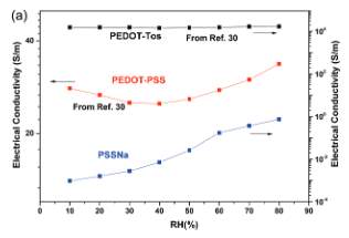
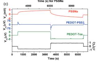
Figure 1. Electrical conductivity vs humidity for: PEDOT-PSS, PEDOT-Tos, and PSS-Na.
From the results from Figure 1 on the left half, it is shown that there is an exponential growth in the overall conductivity of PSSNa system with humidity. In this system electronic conductivity is represented by ionic conduction whereas PEDOT-PSS has both the electronic and ionic charge carriers representing overall electronic conduction; as a result, the material has declined in electrical conductivity up to 40% with humidity [5]. The reason is because electronic conduction is the dominating one when compared to ionic conduction. The results also show that PEDOT-Tos is independent of humidity [5].
In Figure 1 on the right half, when temperature increases the open circuit voltage increases for the PEDOT-Tos. Then, within 30 secs it plateaus to 9 micro volts. For the PSSNa after 100min the voltage is 5-10 millivolts and no correlation between temperature and voltage is observed [5]. For the PEDOT-PSS there is a steady increase in voltage for the first thirty seconds before saturation time is reached; the voltage then peaks to 380 micro volts when the humidity is 100% [5]. The voltage then reduces to 4-10 micro volts. The dependence of thermovoltage peak value indicates that there is a contribution of ionic transport in the thermovoltage versus time evolution [5].
Figure 2 gives a representation of different regions of the Voc vs time curve and the mechanism it undergoes [5]. Thermodiffusion of holes from the hot end to the cold end happens when temperature difference is applied. The resultant of that is the Voc in the region (i) of the curve. Since the PEDOT-PSS is a mixed ionic electronic conductor, in addition to the thermodiffusion of holes it is expected to have the thermodiffusion of protons [5]. This creates an internal electric field which dominates the one developed by the thermodiffusion of holes. In the region (ii) of the curve ionic contribution is reflected in the higher value of the Voc [5].
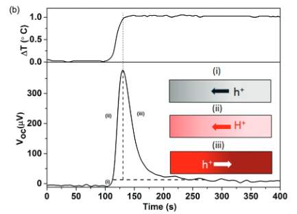
Figure 2. Voc evolution in mixed conductors
In the mixed conductors, the cationic currents and holes are interrelated where as a result the internal field; the internal field is developed due to the higher proton concentration on the cold side leads to an opposite h+ drift current towards the hot end as shown in the figure above [5]. This opposite hole current leads to the decrease of the Voc in the region (iii) of the curve.
Electrical output versus time evolution for the three different types of materials are observed when an external resistor is connected to the hot side and cold side of electrodes. For PEDOT-TOS (electronic conductor), thermodiffusion of holes leads them to the cold electrode [5]. Therefore, the current is constantly produced. For PSSNa (ionic conductor) with the difference in temperature, slowly with respect to time concentration gradient of ionic charge carriers arise to reach high and constant Voc [5]. The problem here is that ions cannot pass the external circuit to an electrical double layer at the electrode (metal). In the case of PEDOT-PSS (mixed conductor), it needs to be confirmed that the ionic moves are similar to the PSSNa. To determine this, the amount of charge flow from the hot to cold electrodes after applying a load resistor needs to be measured.
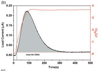
Figure 3. Electrical Characterization
In Figure 3, the curve represents the measurement over the load resistor over time from the voltage drop [5]. Output current is calculated. At 80 % humidity and at 3.7o C the PEDOT-PSS current rises and reaches a maximum peak as ∆T gets constant. Then it again reduces and becomes constant. This constant is due to a phase electronic thermo-effect while the current rise and fall is due to an ionic electric effect [5]. Based on the experimental data it can be concluded that ionic changes are reorganized throughout the PEDOT-PSS and not only among the bulk-electrode interface.
The time dependence of PEDOT-PSS mixed ionic electronic conductor shows that the charge carrier contributes to the thermovoltage (Voc) at 100% humidity when ∆T of 1o C was applied [5]. The electrical experimental shows that the PEDOT-Pss at high humidity is under ∆T proton thermodiffusion; this is followed by internal electro chemical reaction. This happens because of the nature of conduction of charge carriers. Therefore, the polymer system behaves as a device where in the power generated by the ionic charge carrier is dominated due to the electronic shunt or the internal load [5].
Another material examined is Se rich Ag2Se. This is another material widely used in the applications of thermoelectric generators. Therefore, its thermal properties were examined. The efficiency of thermoelectric materials is given by ZT which is called the thermoelectric figure of merit [7]. It has three material parameters along with the absolute temperature T. The equation to find the thermoelectric figure of merit is shown in equation 1.
ZT=S2σT/κ (1)
S is the Seebeck thermopower coefficient, κ is the thermal conductivity and σ is the electrical conductivity. Previous studies state that Bi2Te3 based alloy is the only one commercial material used as thermoelectric refrigerator at room temperature. Since Te is rarely available in earth there is a need to discover Te-free thermoelectric materials for industrial applications. Recent studies demonstrated that Ag2Se is a good example because of the chemical properties that are like copper and showed extremely low thermal conductivity and a high thermoelectric performance when observed for copper selenide and few of its derivatives. Its low band gap similar to Bi2Te3 results in a maximum ZT thermoelectric figure of merit values around room temperature [7]. These materials are commonly used in other research applications for thermoelectric materials.
In this study, to find out transport during first order phase transitions few Se rich samples, Ag2Se1+x (x=0,0.02,0.04,0.06,0.08,0.1) compositions were slowly heated up to 1273K and held there for 12 hours [7]. The samples were then annealed at 723K for 7days. This process formed ingots that were finely grounded and by spark plasma sintering these were sintered at 680K for 5min under 60Mpa pressure to get pellets [7]. During this process, boron nitride layers are coated on the inner, top, and bottom surfaces of the dies to prevent the migration of Ag ions under the large electric current [7].
Various parameters, such as the electrical conductivity and Seebeck coefficient were measured using the modified thermal expansion equipment [7]. Thermal diffusivity is measured by the laser flash method where the atmosphere is Ar with a 1K temperature step. The hall coefficient is measured using PPMS, and the hall mobility is calculated by the µH=RH σ. All these samples were examined by XRD [7].
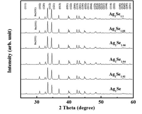
Figure 4. XRD Patterns
Figure 4 shows the XRD patterns for Ag2Se1+x (x=0,0.02,0.04,0.06,0.08,0.1), all the samples crystallize in orthorhombic structure also an additional peak of Se (101) can be seen in samples with Ag2Se1.06, Ag2Se1.08, Ag2Se1.1 [7]. The intensity of this peak decreases with the Se content in the sample.
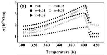
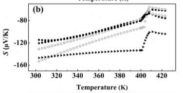
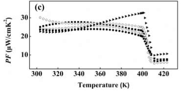
Figure 5. Thermal Properties vs. Temperature
Figure 5 shows the thermal properties such as electrical conductivity, Seebeck coefficient, and PF=S2 σ in three separate plots [7]. Se with 1.1 content is not considered anymore because of its chemical inhomogeneity from the Ag ion migration during the sintering process. From the first plot (of the Seebeck coefficient) in Figure 5 it is seen that by the slight addition of Se, the electrical conductivity at room temperature decreases [7]. This is not the case before phase transitions where it increases with the temperature showing a semiconductor behavior. According to the experimental values observed, electrical conductivity hugely drops with the values at high temperature phases showing a metallic behavior [7]. The second plot in Figure 5 shows the negative values for all the samples which indicates that electrons are the majority charge carries [7]. The Se in the compositions has not provided enough holes so when the XRD patterns are examined it is clearly proved that excessive Se atoms are not entering the lattice but exist as impurity phases in the materials [7]. The value of the Seebeck coefficient at room temperature increases when x increases from 0 to 0.08; this shows that it could still decrease the carrier concentration with increase in its content [7]. The absolute value of Seebeck coefficient decreases with temperature before the phase transitions. The temperature dependence of S and σ is the opposite trends. Lastly, the third plot in Figure 5 shows the power factor of all the samples. The largest is found for x=0.06. The PF decreases with temperature before phase transitions except for x=0.08, it shows a positive dependence on temperature since decrease of S is not so strong [7]. Comparatively with that of S and σ PF also drops during the phase transition and the figure shows that the PF does not show any obvious changes when the amount of Se is not largely excessive.
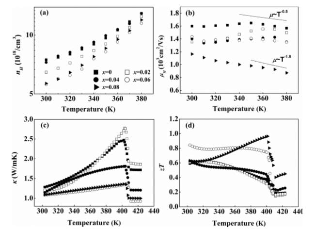
Figure 6. Temp. dependence of carrier concentration, mobility, thermal conductivity, and ZT.
In Figure 6, it is shown that when the temperature dependence of electron concentration is measured it showed a positive dependence on temperature. However, there is a decrease in the nH with the increase of Se content [7]. The electron mobility decreases with the large Se contents due to electron scattering by the impurities of Se [7]. All the samples considered showed a low thermal conductivity. Conductivity due to the electrons is the dominant one when compared to lattice thermal conductivity [7]. x=0.08 shows the highest value of ZT at 401K which is comparable with that of Bi2Te3.
To reveal the thermoelectric properties, a single band model is used for Ag2Se. The model trend is also shown in the left-hand plot of Figure 7 where all the samples completely merged with it except x=0.08 [7].
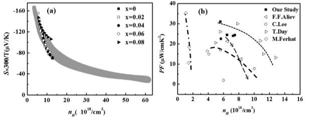
Figure 7. Single Band Model of Ag2Se
This may be due to large Se impurity phases. When the literature is considered the single band model has predicted an optimum nH, but the Ag rich compositions has nH values far above the optimum value. And, with the increase in Se atoms it is reduced to half the value but could not reach the optimum value. In the right-hand plot of Figure 7 it shows the values observed in different studies used to find the optimum value. However, the lowest found is also larger than the optimum value [7].
Using the recently developed measurement system the temperature dependence of ZT was measured. It was shown that at room temperature Ag2Se has peak ZT value, but for x=0.08 shows the peak value at 401K which is just below the phase transition [7]. This may be due to the scattering of extra Se carriers [7]. Since the electron concentrations in x=0.06, 0.08 are close in value, this means the defect concentrations are also very close. However, x=0.08 has more impurity concentration leading to more scattering. This carrier scattering also effects the thermopower and the temperature at which its peak values are obtained [7].
The first order phase transitions occur easily once the thermal vibrations overcome the energy barrier between the high and low temperature phases [7]. Therefore, it can be summarized that by the addition of excessive Se content the carrier concentration values decrease towards the optimum value. This then leads to the high power factor and ZT with the peak value close to 1 at 401K. Se impurity phases can shift the temperature realizing the maximum value of ZT to high temperature [7].
The information known on these materials can be applied towards applications such as wearable thermoelectric generators. Even further, their material properties must be optimized so that they can improve efficiency of the devices created.
There have been previously performed experiments that support the verifiability of the article “Bendable thermoelectric generators composed of p-type and n-type silver chalcogenide nanoparticle thin films” [4]. Another group of researchers has produced a successful and wearable thermoelectric generator; they wrote a paper called “A wearable thermoelectric generator fabricated on a glass fabric” [3]. Like the first paper, these researchers realized that they had to overcome the tradeoff between the need for high power output density and the requirement of flexibility. For a material to be more flexible, it generally is more difficult to produce the high power output. However, in this paper, they have managed to surpass that tradeoff and produce a thermoelectric generator with both flexibility and a high power output, as was required [3]. Their end goal was to create a flexible and powerful thermoelectric power generator that would convert body heat into electrical energy. Ideally, this could be used for mobile electronic systems that are self-powered, such as medical sensors or smart watches. If this process were scaled up, it could be applied in much larger ways, such as hybrid energy harvesting systems like flexible solar cells and piezoelectric devices [3].
To build this device, the glass fabric-based substrate was utilized. The use of these techniques results in a self-sustaining structure that does not require top and bottom substrates – this allows for further flexibility and minimal thickness [3]. With an allowable bending radius of 20 mm, after performing bending tests within that range, there was no change in performance for 120 cycles [3]. This is important because to be called flexible, for these purposes that was defined as the ability to withstand repeated tensile and compressive strains. Not only does the substrate need to be flexible so that it may be worn, but it must also have a high thermal tolerance so that it may be able to endure the extreme conditions it must undergo during the fabrication process. It is also important that the thermal energy loss is minimized; this is crucial to improve energy efficiency while the thermoelectric generator is operating on the heat source [3]. Most commercially used substrates, such as Silicon, Al2O3, or a polymer film, result in large thermal loss that limits energy conversion efficiency. The energy loss is larger in certain types of materials such as thin films, super lattices, nanowires, or quantum dots because the thickness of the substrate determines the output performance [3].
The formation of the thermoelectric thick films on the glass fabric-based substrate was done using a screen-printing technique [3]. First, the n-type and p-type thermoelectric materials were formed. The synthesized Bi2Te3 paste, which is the n-type, and the Sb2Te3 paste, the p-type, were both synthesized as precursors and were printed onto the glass fabric [3].
First the n-type paste was printed as a thick film onto the fabric; this was followed by the formation of the p-type thick film. Both films undergo an annealing process under 530°C in a Nitrogen atmosphere. This was necessary for crystallization and densification in the film. Fortunately, the fabric is not damaged in this high temperature due to its natural high thermal tolerance of 600°C [3]. The liquid paste infiltrates the glass-fabric meshes because of the capillary phenomenon which forms the thermoelectric thick films.
he result is that hundreds of n-type and p-type dots are printed and arranged onto the substrate. The advantage of this self-sustaining structure is that it does not require an external substrate; this allows for minimizing the thermal energy loss. Additionally, the glass fibers now buried within the thermoelectric materials act as a thermal blocker. This results in further reduced thermal conductivity of the printed thermoelectric film [3].
Some properties of the thermoelectric on the glass fabric are first examined by beginning with a model using Fourier’s Law and electrical resistivity equation to theoretically calculate electrical and thermal properties [3]. To prove these theoretical calculations, numerical simulations were performed as well so that the effects of the glass fibers inside the thermoelectric material can be visualized and verified. Measured from the experimental prototype, the Seebeck coefficients of the n-type and p-type materials were respectively found to be 141
μV/K
and 98
μV/K
[3]. The total Seebeck coefficient was decided by the thermoelectric materials around the insulation region because the carrier transport paths are located only along the thermoelectric materials when the conducting and non-conducting materials are connected in parallel. Another material property that was calculated is the electrical conductivity. The electrical conductivities were related to the thickness and decreased as the thermoelectric thickness to film thickness ratio decreased. For the n-type component, the electrical conductivity was found to be
0.67 x 10⁵S/m
whereas the p-type component’s electrical conductivity was found to be
1.5 x 10⁵S/m
[3]. The electrical conductivities decrease as thickness decreases because the portion of the insulation region. This is because the glass fibers within the material interrupt the phonon flow, which ultimately leads to the low thermal conductivity of the entire piece [3].
An additional portion of this experiment was to create an embedded Copper film in the polydimethylsiloxane (PDMS) elastomer for interconnection [3]. The adhesion between a copper film and PDMS is delicate and vulnerable and often results in the delamination of the copper film. This was solved by developing a method called the Nickel peel-off method. This method paired with fabricated a screen-printed copper film embedded in the PDMS displays no rubber delamination during bending. This is because the PDMS enters the porous screen-printed copper film from the capillary phenomenon and is strongly connected with the copper film that results in an electrical conductivity of
2.4 x 10⁷S/m
[3]. These results are 60% lower than bulk copper but is enough for the interconnection. The next step is to integrate the copper paste on the top and bottom plates made of
Ni
/
SiO2
/
Si
wafer [3]. This film is annealed at 700°C for 5 minutes to form thermoelectric dot couples on the glass fabric. The nickel interlayer between the thermoelectric film and silver paste reduced contact resistance of the metal thermoelectric film [3]. The thermoelectric on the glass fabric is then placed between two plates and bonded together using the silver paste, then annealed for 5 minutes at 200°C to harden the silver paste. The sample is then dipped into PDMS to fill the gaps between the plates with the elastic polymer, which reduces thermal energy loss by convection [3]. The sample is then hardened at 90°C for 40 minutes [3]. Rigid plates are peeled off in water immediately after crack growth, which results in the transfer of the nickel and copper layer to the thermoelectric generator. Ni layers are removed by etching in diluted mixture of sulfuric acid and hydrogen peroxide [3]. The result is a prototype with 8 couples of n-type and p-type thick films made of Bi2Te3 and Sb2Te3.
Two prototypes were fabricated; the first of which is the one previously described, and the second a control sample made with a commercially used substrate of Al2O3 for comparison. The internal resistance stability under bending stress was investigated along two directions, with no distinct change in the resistance within the allowable bending radius of 20 mm. The two thick films were experimented on, and material properties were calculated such as the Seebeck coefficient, the electrical conductivity, the thermal diffusivity, specific heat, and thermal conductivity. The thermal conductivity was found as a result of the experimentally found thermal diffusivity, specific heat, and density. No directional difference was found for each property, which confirms that the thermoelectric transport properties are isotropic [3].
Flexibility and high power output was required for the application of a wearable thermoelectric generator, which were both confirmed throughout the fabrication process and experimentation on the prototypes. This power density could be improved upon even further if the ternary thermoelectric alloys with larger ZT values are used in conjunction with this technique. These processes could be used in a larger scale to produce impressive applications, such as whole hybrid systems for energy harvesting, especially paired with flexible solar cells and piezoelectric devices. Overall, this prototype has made leaps and bounds towards improving the issue of compromising between power output and flexibility.
These materials and procedures are not the only way to build a thermoelectric generator. Another method is to use solution-processed nanocrystals instead of the n-type and p-type nanoparticle thin films on the flexible glass fabric. These solution-processed nanocrystals thermal properties are primarily examined to see how well they perform rather than executing the material as a thermoelectric generator. It is expected that this research would be applied in the future towards a prototype of a thermoelectric energy harvester.
Thermoelectric thin films offer a unique lower profile, which is crucial for fitting themselves into the current bundles in microelectronic gadgets. A long time ago, vacuum deposition and chemical vapor (which is very costly) were being utilized to create inorganic TE thin films with high ZT. Because of the expense of the previously mentioned procedures, Solution-processed nanocrystals (NCs) was presented; this procedure is more flexible, versatile, and is a financially savvy substitute for growing superior thin film electronic gadgets.
Recall that the execution of thermoelectric gadgets relies upon the dimensionless figure of merit (ZT) of the materials, the utilization of nanostructures into the thermoelectric material decouples the S, σ, and K; this fills in as a gigantic advantage when contrasted with the customary thermoelectric materials with between reliance of S, σ and K. [1]. On one hand, the inexhaustible interfaces between nanocrystals scatter the phonons to lessen the K. Then again, the quantum restriction impact of the NCs achieves neighborhood increment of the electron density of states close to the Fermi level, which offer ascent to the improved S[1]. In spite of the mentioned advantages, a noteworthy snag of utilizing solution processed NCs for superior TE gadgets lies in the way that the insulating native organic ligands obstruct the charge exchange among NCs and the huge interface of NCs; this likewise adversely affects the charge exchange and therefore the σ of NC films is unavoidably low [1].
In this study, an approach to redress this issue is analyzed by manufacturing a TE thin film with lead chalcogenide. This procedure involved a layer-by-layer technique where the essential constituent layer was produced by spin coating the solution containing unadulterated PbTe NCs or the blended PbTe and PbS NCs (PbTe/PbS), i.e., NC ink onto the substrate by a two-step interface engineering treatment; (1) the PbTe or PbTe/PbS layer was subjected to ligand exchange by ethylenediamine, and (2) as-exchanged layer was annealed at various temperatures for proper coupling of nanocrystals [1].
This treatment delivered PbTe thin films with ZT around 0.26 at 405K and when a solution-processed 5% PbS NCs was brought into the PbTe NC thin films, a higher ZT estimation of roughly 0.30 at 405K was accomplished [1]. This upgraded change is because of the presentation of heterojunctions created between the PbS and PbTe. Carrying out Ligand exchange by hot ethylenediamine (50oC), the PbTe NC thin films were annealed at several temperatures. Utilizing the Scherrer equation, the domain size of the thin films expanded with annealing temperature. [1].
The investigation did demonstrate the accompanying outcomes. The thermoelectric execution of the unadulterated PbTe NC thin films after treated by hot ethylenediamine and annealed at various temperature; the thin films have a positive S, uncovering that the PbTe NC thin films are p-type in nature. [1]. Additionally, conductivity of all the thin films is essentially enhanced with increasing annealing temperature, which demonstrates an abatement of interface dissipating of transporters [1]. Another result from these experiments are that the power factor S2σ at 400oC demonstrates the best outcome due to the synergetic effect of S and σ [1]. Finally, the estimation of the PbTe NC films increments by annealing temperature, which is attributed to the diminishing interface phonon scattering by fusion of NCs [1]. The choice of ligand exchange operators is basic for improving the execution of solution-processed thermoelectric NC material as we saw that ethylenediamine is superior to ammonium thiocyanate [1].
Estimation of band bending at the interface were likewise inspected dependent on the accompanying presumptions: 1) at the level band condition, the valence and conduction bands of the two systems are adjusted by accepting a typical vacuum level; 2) the extent of the band bending is dictated by expecting that electrons and holes transfer over the interface until the point that a typical Fermi level is achieved; 3) the materials are intrinsic Fermi levels amidst bandgap [1].
Figure 8demonstrates the common energy barrier in the nanocomposite. It very well may be seen that low energy carriers are scattered more than the high energy carriers over the energy barrier. Further studies are imperative to uncover the impacts of the blocking impacts of the minority transporters which enhances S.
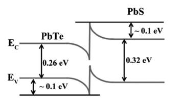
Figure 8. Band Bending
From this examination, we can infer that PbTe/PbS NC thin films of an incredibly high ZT estimation of ≈0.30 at 405K have been effectively prepared through the basic blend of NC solution, ligand exchange with ethylenediamine lastly, thermal annealing at 400°C which keeps up the wealth interfaces between NCs to scatter the phonons and decreases thermal conductivity. Ligand replacement with ethylenediamine was embraced to help necking between NCs, bringing about an increased electrical conductivity [1]. Overall, the increase of electrical conductivity shows that an improvement upon the materials is important and could be useful for bettering of thermoelectric generators should these concepts be applied.
Thermoelectric generators can be improved utilizing these various materials and fabrication processes. Of course, the application method can always be improved. This next research was intended to optimize the device itself, as well as ensure the materials are flexible and have fitting thermal properties.
Examination of late advances in the improvement of flexible thermoelectric materials, (for example, polymer-based materials and screen-printed paste-type inorganic materials) and gadgets for wearable human body-warm energy reaping applications is being done with an objective focused on developing applications for specific medical sensors (healthcare monitoring) where wearable thermoelectric generators can have focal points over other energy sources [2]. For as far back as decade, wearable gadgets and sensors have met such a large number of requirements and applications yet the test of energy self-sufficiency for a broadened benefit/service period turned into a test and that incited analysts to examine building up a technique for wearable gadgets equipped for collecting energy from the human body to create power with the guide of a thermoelectric generator.
It ought to be noticed that a high effectiveness thermoelectric material should be electrically exceptionally conductive while thermally inadequately conductive as appeared in what is known as the material figure of merit, ZT = S2σT/K where S is the Seebeck coefficient, σ is the electrical conductivity, T is the absolute temperature, and K is the thermal conductivity [2]. The factor S2σ in the numerator is called the power factor.
A thermoelectric generator (TEG) is known to be a solid-state gadget fit for converting heat into electricity [2]. The impact of TEG in this examination is seen when it acquires contact with the human body, empowering heat from the body to flow through the TEG in view of temperature distinction between the skin and the encompassing condition. The system of warmth stream makes a voltage in the TEG by what is known as the Seebeck effect which empowers helpful work when associated with an outer circuit.
Concerning the area and encompassing conditions, occasionally the warmth dispersal from a human body changes. For instance, in an indoor circumstance, warm stream is around 1-10mW cm-2on an average of 22oC (ambient temperature) whereas heat flow of 10-20 mW cm-2is experienced on the wrist because the heat-carrying radial artery is situated close to the skin [2].
The state-of-the-art Bi2Te3-based inorganic materials had a low power density of 60 µW cm-2 under indoor conditions due to the non-flexibility of the inorganic materials and the costly and non-versatile assembling techniques [2]. In this manner, conjugated polymers have been rigorously examined for thermoelectric energy transformation because of their intrinsically low thermal conductivities, adaptabilities, light-weight, material wealth and solution processability. IMEC (Interuniversity MicroElectronics Center) exhibited in the previous decade the common sense of hundreds of microwatt-level power generation from human body heat, for example, the watch-sized TEGs. TEGs were additionally utilized as wearable power supply for a heartbeat oximeter on a finger which effectively produced power (~ 100 µW) to work the beat oximeter. [2]. It ought to be noticed that the output power and voltage are relative to the surface area of a TEG.
Figure 9 demonstrates a few kinds of wearable sensor gadgets that are fueled by flexible thermoelectric energy harvesters. These are only a few different ways that this phenomenon could be utilized to improve human life, in particular, health monitoring services. According to this figure, each sensor in various places would wirelessly speak to a cell phone for user viewing and monitoring. These short-range wireless communication technologies provide efficient, ultra-low power consumption suitable for energy harvesting devices [2].
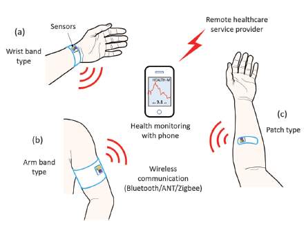
Figure 9. Wearable Sensor Devices
As of late, an ultra-low TEG-fueled body sensor node SoC (system on chip) has been produced in a business 130nm CMOS innovation for ECG, EEG, and EMG applications. Just 19 µW control is devoured by the chip for 0.013% transmission obligation cycle with 14 µA current at 1.35V [2]. A commercially accessible TEG generation of 60 µW with 30 mV yield voltage was adequate to control this sensor node without a battery. It is recommended that the utilization of a TEG with 70 µW or a higher power for little temperature contrasts of 0.3– 1.5°C in embedded therapeutic gadgets; for example, pacemakers and defibrillators to maintain a strategic distance from extra medical procedure expected to supplant batteries in these gadgets [2]. Thermoelectric materials such as Bi2Te3/Sb2Te3 (inorganic semiconductors) have high ZTs, are not flexible, not savvy to fabricate, henceforth, polymer-based thermoelectric materials have picked up part of consideration because of its mechanical adaptability/flexibility, lightweight, ease blend and solution processability. In addition to this, their thermal conductivities are normally low because of the profoundly disarranged structures which are reasonable for thermoelectric applications. The inconvenience is that they have normally lower power factors than those of inorganic TE materials which is the motivation behind why conjugated polymers have not been to a great degree contemplated for thermoelectric so far. Electrical conductivities as high as 1000 S cm-1 or significantly higher have been effectively accomplished by oxidizing (p-type) or reducing (n-type) [2]. To enhance the low Seebeck coefficients of organic semiconductors, hybrid nanocomposites with inorganic thermoelectric materials were created.
Now that different materials have been examined, the next step would to answer the question of how best to implement and execute a thermoelectric energy harvester in a typical real-life setting. For example, how should the device be positioned such that it harvests enough energy from the body without being inconvenient or uncomfortable for the user? This next group of researchers performed experiments to determine the best way to execute the thermoelectric energy harvester.
The science behind thermoelectric generators has been making great strides towards the improvement of wearable thermoelectric devices. The applications are widely varied, but impressive in their usefulness. One use of a self-powered device would be a wireless sensor, such as a monitor for heart health or some such application. Ideally, this type of device would need to meet certain requirements for it to be feasible. These requirements would be that the wearable wireless sensor must be very small, unobtrusive, able to be completely hidden, reliable, and should function for the entire service life of a piece of garment without requiring recharging or battery placement [6]. These requirements answer the question of what makes a thermoelectric human body heat energy harvester feasible and marketable.
There are a few questions to address as to what will best allow for the balance between functionality and comfort. Because it is a thermoelectric generator relying on human body heat, one of the most important questions is where to place the wearable sensor. It should be placed somewhere such that it can maximize the heat source from the skin. However, it also must meet the other requirements, such as the ability to be hidden, as well as comfort for the wearer. There were a few options that were considered for the placement of the wearable sensor: the chest, head, and wrist (at the warmest zone, which is close to the radial artery). There were advantages and disadvantages to each placement zone. For placement on the chest, a significant amount of heat can be extracted. However, the chest is more sensitive to local cooling in cool weather. Therefore, in the interest of personal comfort, the heat flow must be substantially limited to meet the rest of the requirements [6]. For the placement around the head, the clearest disadvantage is that it is near impossible to keep hidden in an office setting. Therefore, regardless of the energy harvesting advantage, it simply cannot reasonably meet the low visibility requirement. Lastly, the wrist was considered as well. There is a disadvantage in the fact that there is a lower skin temperature to harvest energy from. However, it was the most comfortable, easily hidden, and could still obtain maximum power at low ambient temperatures despite the lower skin temperature. Therefore, the placement of the thermoelectric generator was chosen to be worn at the wrist [6].
The reason the wrist location still produced maximum power was because the temperature difference between the body core and skin depends on the location on the body and the ambient temperature, which indicates that the thermal resistance of heat path in the body from its core to the skin depends on the location of the thermoelectric generator, clothes, wind speed, all in addition to air temperature [6]. To experimentally prove that the wrist was the ideal location for this application, the researchers measured skin temperature with a thermistor in the middle of the forehead in still air. This showed that a human demonstrates variable core-to-skin thermal insulation depend on many factors, such as ambient temperature even in locations proximal to body core organs like the brain [6]. Therefore, this temperature measuring experiment confirms the dependence of body thermal resistance per body location point, and that the radial artery was found to be the optimal option since beyond the temperature range, the heat flow is highest among the studied locations [6]. It was also noted that there is a dependence of body thermal resistance on heat flow at fixed ambient temperature and fixed location of the thermoelectric generator.
It was determined that the key factor for reaching maximum power is its thermal impedance match to the thermal impedance match to the environment [2]. This means that this is the electro-thermal equivalent of electrical matching of the load and generator impedances. It was also determined that the only way known thus far to improve the power output of a wearable thermoelectric energy harvester would be to improve the material quality [6].
Next, there was another question to be answered in the execution of a wearable thermoelectric energy harvester. This would be the question of how to implement the device into a garment. Recall the requirements are such that the thermoelectric generator must be hidden, not need recharging or replacement, and should be able to withstand the lifetime of the garment as well. There were four ways that were investigated to hide the thermoelectric energy harvester within a garment.
The first was to place a hot plate in direct contact with the skin under a textile with the cold plate at about 4 mm from the cotton layer. This resulted in the most efficient solution; however, visually the presence of metal plates is not aesthetically pleasing and therefore does not fit each requirement. This was unfortunate because the cold plate is optimal because both sides participate in the heat exchange with ambient air, which is how this method is the most efficient [6].
The second method investigated was to place the thermoelectric energy harvester in the cotton of a professional button-up collared shirt with a weak elastic band holding the device in place on the chest. A few different measurements were taken at the three positions of cotton, such as: cotton was tied to the cold plate, cotton pulled away from the thermoelectric energy harvester (to make an air gap), and with the cotton pulled to the sides (to leave the thermoelectric energy harvester completely open to the air). It was found that hiding the device under the shirt was ultimately feasible at negligible loss of power if the cotton was in contact was the cold plate, which would cause the cotton to act as the radiator of the thermal energy harvester [6]. It was also found that the lack of an elastic band produces approximately the same power output with the presence of the elastic bands and the external cold plates; therefore, it was found that the elastic bands added a negligible effect and could be used with minimal power difference. This is useful for other potential options in the future; however, it was not what was ultimately chosen as the optimal solution.
Overall, it was found that the low ambient temperature did not affect the overall body heat content and thermal comfort, of which the confirmation was the main goal of these experiments. Additionally, it was confirmed that the shirt was the best solution of the wearable thermoelectric generators in the interest of comfort. It should also be noted that it was concluded that the power generated by these wearable generators is not dependent on the person’s metabolic rate, but rather their overall body heat content and relative air speed [6]. This was confirmed by an experiment through which a cyclist wore a thermoelectric generator shirt; the cyclist would compare readings from when he was cycling compared to when he was at rest.
In conclusion of these series of experiments testing out the feasibility of a wearable thermoelectric energy harvester, at any of the studied ambient conditions, there was no thermal discomfort. The thermal energy harvester inserted into the shirt was found to be the optimal solution, because it required minimal modification to an existing garment in the way of gluing and sewing into the existing shirt [6]. Because of this, the device is comfortable, which meets a large requirement for these generators to be competitively sold. Additionally, the shirt utilized in these experiments included periodic machine washing, drying, and ironing. The ideal generator would have to be able to withstand these processes to the last the lifetime of the garment. Not only is the thermoelectric energy harvester comfortable, it also is reliable as a power supply for small wearable electronics such as health monitoring devices.
Unfortunately, the cost for the thermoelectric generators is still much higher than its main competitor, batteries. While batteries must be replaced, they are still so inexpensive that the thermoelectric generator is still a far way off from being remotely competitive. When thermoelectric generator materials eventually decrease from their current ten times the expense of batteries, then they will truly be able to compete. This is possible as fabrication technologies improve and decrease the cost of thermoelectric energy harvesters.
Conclusion
Overall, thermoelectric generators are an interesting application of thermoelectric materials. The ability to harvest energy from a temperature difference, such as from body heat, is extremely useful. Materials with these thermoelectric properties will be improved and optimized so that they can be utilized in devices that harvest this heat and power themselves. This opens so many doors for health monitoring devices. This is remarkable, especially if the fabrication processes combined with the right materials become inexpensive enough for the devices to rival other options, such as battery powered sensors. To reach that point however, it is necessary to explore different combinations of thermoelectric materials to achieve this. Each of these researchers have examined slightly different materials and fabrication processes in the interest of furthering the application of thermoelectric generators.
References
[1] D. Ding, D. Wang, M. Zhao, J. LV, H. Jiang, C. Lu, Z. Tang, Interface engineering in solution-processed nanocrystal thin films for improved thermoelectric performance, Adv. Mater. 29 (2017) 1603444.
[2] J. Bahk, H. Fang, K. Yazakawa, A. Shakouri, Flexible thermoelectric materials and device optimization for wearable energy harvesting, J. Mater. Chem. C 3 (2015) 103626-10374.
[3] S.J. Kim, J.H. We, B.J. Cho, A wearable thermoelectric generator fabricated on a glass fabric, Energy Environ. Sci. 7 (2014) 1959–1965.
[4] S. Yang, K. Cho, Y. Park, S. Kim. Bendable thermoelectric generators composed of p- type and n- type silver chalcogenide nanoparticle thin films, Nano Energy 49 (2018) 333-337.
[5] U. Ail, M.J. Jafari, H. Wang, T. Ederth, M. Berggren, X. Crispin, Thermoelectric properties of polymeric mixed conductors, Adv. Funct. Mater. 25 (2016) 6288-6296.
[6] V. Leonov, Thermoelectric energy harvesting of human body heat for wearable sensors, IEEE Sens. J. 13 (2013) 2284–2291.
[7] W. Mi, P. Qiu, T. Zhang, Y. Lv, X. Shi, L. Chen, Thermoelectric transport of Se-rich Ag2Se in normal phases and phase transitions, Appl. Phys. Lett. 104(2014) 133903.
Table 1. Contributions
| Tabulation of Contributions | |
| Student Name | Sections Written (pages, paragraphs) |
| Kelsey Hughes | Page 1, paragraph 1; page 2, paragraph 3; page 8, paragraph 4 to page 11, paragraph 1; page 12, paragraph 4; page 14, paragraph 2 to page 17 |
| Isaac Akinboye | Page 1, paragraph 2 to page 2, paragraph 2; page 11, paragraph 2 to page 12, paragraph 3, page 12 paragraph 5 to page14, paragraph 1 |
| Mahima Gudipudi | Page 2, paragraph 4, page 3 to page 8, paragraph 3 |
Cite This Work
To export a reference to this article please select a referencing stye below:
Related Services
View all


Related Content
All TagsContent relating to: "Mechanics"
Mechanics is the area that focuses on motion, and how different forces can produce motion. When an object has forced applied to it, the original position of the object will change.
Related Articles

DMCA / Removal Request
If you are the original writer of this research project and no longer wish to have your work published on the UKDiss.com website then please: