Manufacturing Technologies Optimization: CNC Milling
Info: 12078 words (48 pages) Dissertation
Published: 9th Dec 2019
Tagged: Manufacturing
Manufacturing Technologies Optimization: CNC Milling
Abstract
CNC milling is essential part of the manufacturing process. When machining programs are generated, a lot of factors need to be taken into account. Depending on the selected parameters, machining time, surface finish can vary.
In this project, optimisation of the material removal process on a casting tool based on the results from the cutting simulations from PTC Creo is the main aim of this project. Part design is an important step and the decision to move forward with a right design is also key and then to successfully prepare the design for die-casting also ensuring the adequate casting and machining requirements were met. Then the machining of the casting tool was completed and an estimated machining time was produced. With this result the process was further optimised to achieve the most cost effective time possible. The surface finish and step over was studied to see how they correlate and how one affects the other. With a final optimised machining operation.
Contents
2.2 Disadvantages of CNC Milling
7. Model Preparation for Casting
7.1 Enabling absolute accuracy
11. Machining time optimisation
12. Surface Finish optimisation
List of Figures
Figure 1 Keyboard cover made through a CNC machine (DARTON Dynamics, 2018)
Figure 2 A 3 axis CNC milling machine (Ebay, 2018)
Figure 3 Front and side profile of designFigure 2 A 3 axis CNC milling machine (Ebay, 2018)
Figure 3 Front and side profile of design
Figure 4 View from all sides of the valveFigure 3 Front and side profile of design
Figure 4 View from all sides of the valve
Figure 5 Dimension for connecting rod (Onshape, 2017)
Figure 6 Completed part design following the dimension above
Figure 7 Redesigned connecting rodFigure 6 Completed part design following the dimension above
Figure 7 Redesigned connecting rod
Figure 7 Redesigned connecting rod
Figure 8 The plane used for the draft hinge
Figure 8 The plane used for the draft hingeFigure 29 List of cutting tools used
List of Tables
Table 2 Abbreviations used within the formulas for the equations
Table 4 Recommended DOC values
Table 5 Table of dimensions and corresponding values for tool parameters.
Table 6 Final machining time for volume 1
Table 7 Final machining time for volume 2
CNC, this manufacturing technology importance’s is underestimated by most people.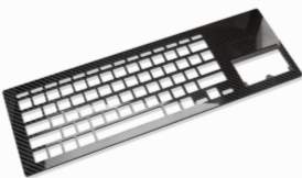 There are most things that we use that hasn’t in its manufacturing utilized CNC technology in some way. It is present in products and objects of everyday life as e.g. cars, airplanes, components of machines of all types, moulds for tools used for household items, machines, medical prosthetics, cell phones and toys etc.
Figure 1 Keyboard cover made through a CNC machine (DARTON Dynamics, 2018)
Figure 2 A 3 axis CNC milling machine (Ebay, 2018)Figure 1 Keyboard cover made through a CNC machine (DARTON Dynamics, 2018)
Many of the appliances and objects we use every day depend on CNC operations. It is a highly sophisticated piece of machinery that creates components using precise cutting tools. So, what is CNC it means Computer Numerical Control. This means a computer converts the design produced by Computer Aided Design software (CAD), into numbers. The numbers could be considered to be the coordinates of a grid and they control the movement of the cutting tool. In this way the computer controls the cutting and shaping of a material (Ryan, WHAT DOES CNC MEAN ?, 2009).
In contrast to a conventional cutting machine where an operator gives an input and controls the working, whereas for a CNC machine the computerized control unit give the instructions regarding:
1. Tool Control: Tool and tool parameters
2. Feed rate and spindle speed
3. Coordinate System
4. Coolant Control: On/Off, Flood, Mist, etc
1.1 Types of CNC Machines
There are numerous types of CNC machines available. Some of them are listed below:
- CNC Lathe Machine: As a production turning machine, the lathe is designed with bed, which usually lies flat with an extremely fast spinning spindle, CNC lathe machines are versatile.
For this reason, they are used to create parts for a wide range of industries. For example, this type of machine is commonly used in glass working, parts reclamation, metal spinning and metalworking (Haas Outlet, 2015).
- CNC Router machine: Routers are generally for producing larger dimension parts and more commonly built with the idea of cutting wood, plastics and sheet metal in mind.
- Plasma: CNC plasma cutters are used to cut metal and wood and do not require as much power as a CNC router. These machines use a plasma torch to penetrate the material, which is typically wood or sheet metal.
- Laser – CNC laser cutters operate similar to CNC plasma cutters, but instead, a powerful laser is used to cut the material. Lasers can also be used to cut plastic as well (Laique, 2017).
- 3D Printer: A 3D printer does additive machining as opposed to subtractive machining. Instead of starting with a solid piece of material and removing bits of that material to end up with the desired part, the 3D printer starts with a blank canvas and builds a part up layer-by-layer. The 3D printer does this either by using an extruder that pushes a material (typically plastic) out from a tiny nozzle, or by using a laser that quickly solidifies a powder or liquid (Sumu, 2017).
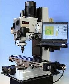 One of the more common and important type of CNC machine is the CNC milling machine. CNC milling is a specific form of computer numerical controlled machining. Milling itself is a machining process similar to both drilling and cutting, and able to achieve many of the operations performed by cutting and drilling machines. Like drilling, milling uses a rotating cylindrical cutting tool. However, the cutter in a milling machine is able to move along multiple axes, and can create a variety of shapes, slots and holes.
Figure 2 A 3 axis CNC milling machine (Ebay, 2018)
Figure 3 Front and side profile of designFigure 2 A 3 axis CNC milling machine (Ebay, 2018)
In addition, the work-piece is often moved across the milling tool in different directions, unlike the single axis motion of a drill.
Typically, CNC milling machines are grouped by the number of axes on which they operate. Most machines offer from 3 to 5 axes, providing performance along at least the X, Y and Z axes.
Advanced machines, such as 5-axis milling machines, require CAM programming for optimal performance due to the incredibly complex geometries involved in the machining process. These devices are extremely useful because they are able to produce shapes that would be nearly impossible using manual tooling methods. Most CNC milling machines also integrate a device for pumping cutting fluid to the cutting tool during machining.
5-axis milling machines are used to produce a wide range of components, and tooling costs involved have continued to become more affordable. 5-axis milling machines are ideal solutions to everything ranging from prototyping and short-run production of complex parts to the fabrication of unique precision components (Thomas, 2018).
Virtually every type of material that can be drilled or cut can be machined by a CNC mill, although most of the work performed is done in metal. As with drilling and cutting, the proper machine tools must be selected for each material in order to prevent potential problems. The hardness of the workpiece material, as well as the rotation of the cutting tool must all be factored before beginning the machining process.
2.1 Advantages of CNC Milling
- CNC machines can be used continuously 24 hours a day, 365 days a year and only need to be switched off for occasional maintenance.
- CNC machines are programmed with a design which can then be manufactured hundreds or even thousands of times. Each manufactured product will be exactly the same for example aircraft parts.
- Less skilled people can operate CNCs unlike manual lathes / milling machines which need skilled operators.
- Being safer to use and handle than conventical milling machine. Modern machines have safety features built in to prevent accidents.
- CNC machines can be programmed by advanced design software such as PTC CREO enabling the manufacture of products that cannot be made by manual machines.
- Modern design software allows the designer to simulate the manufacture of their design. There is no need to make a prototype or a model. This saves time and money.
- One person can supervise many CNC machines as once they are programmed they can usually be left to work by themselves. Sometimes only the cutting tools need replacing occasionally.
- Highly flexible in its operations, can quickly change parameters and machining sequences to adopt to a new job change.
- Less paperwork required than a conventical milling machine therefore, can process prototype production faster which reduces lead time.
2.2 Disadvantages of CNC Milling
- CNC machines are normally more expensive than manually operated machines, although costs are slowly coming down.
- The CNC machine operator only needs basic training and skills, enough to supervise several machines. In years gone by, engineers needed years of training to operate centre lathes, milling machines and other manually operated machines. This means many of the old skills are been lost.
- Less workers are required to operate CNC machines compared to manually operated machines. Investment in CNC machines can lead to unemployment.
- Many countries no longer teach students how to use manually operated lathes and milling machines. Students no longer develop the detailed skills required by engineers of the past. These include mathematical and engineering skills (Ryan, 2009).
- Maintenance is essential for smooth operations which can difficult and expensive to maintain. If the machine does breakdown cost of time and repair can be considerable which could lead to financial trouble if the company is not careful.
- To understand machining constraints and how they affect development cycle from design to manufacture.
- Understand how the combination CADCAM and CNC principles can create more efficient product design process.
- Have to design an appropriate part for casting which would serve a real life purpose.
- To optimise the estimated machining time and surface finish.
- To develop from a conceptual product design a fully featured part suitable for pressure die-casting.
- Modify the model in order to make it suitable for die-casting.
- Design a set of moulding dies.
- Successfully split the workpiece
- Examine the mould parts and check the required draft angles.
- Apply a shrinkage value
- Make a test shot and examine the moulding.
- The solid modelling of a set of moulding dies incorporating suitable cavities and parting surfaces.
- To visually verify the manufacture of the model using NC CHECK.
- The use of CADCAM software to simulate the manufacture of a prototype of the product in tool steel and estimate a machining time.
- Make a process plan and simulate the manufacture of a prototype of the component in tool steel. Estimate the machining time and surface finish.
Machining is the vital activity of a manufacturing organization and milling is one of them. The healthy growth of a country depends upon new invention and research in manufacturing sectors.
Literature review revealed that research was mainly focused on input process parameter such as cutting speed, feed rate and depth of cut and output process parameters such as material removal rate (MRR), surface finish. The Taughi method was also frequently used to optimize the process parameter (Singh, Kumar, & Kumar, 2014).
(Arias, 1983) In this research, a study of the surface roughness produced in end milling of AISI 4140 cold rolled steel, using high speed steel tools, was undertaken. This study assessed the process variability with respect to surface roughness, using different cutting conditions with three different tool diameters. The results of this study indicate that the combined effect of cutting speed and feed rate on surface roughness was highly significant. To achieve better surface finish a combined variation in both factors is necessary. For this tool diameter, the influence of feed rate does not permit the use of large values of cutting speed without deterioration in surface finish.
(Riberio, Cesar, & Lopez, 2017) In this research, the effects of varying four parameters in the milling process, specifically cutting speed, feed rate, radial depth and axial depth. The influence of these parameters on the surface roughness were analysed separately and also the interaction between some of them for the milling machining of hardened Steel. The results show that the radial cutting depth and the interaction between the radial and axial depth of cut are the most relevant parameters, due to their contributions for the minimization surface roughness about 30% and 24%, respectively.
Part design offers many challenges. The entire process from start to finish can be complex in nature from the sketching challenges to the analysis and tool design. The part must be able to meet the lifecycle requirements of the product and be manufacturable. The ability for the other design engineer to understand and communicate to the other disciplines can be crucial point in the product design stage.
Some general steps for part design
- Design Intent – The first thing to determine is what the purpose of the design will be. Is the part valuable enough to go through all these steps and still be cost efficient to produce?
- Robust Modelling Techniques – the part design does not have to be complex the aim should be to keep the design as simple as possible. Many very difficult designs can be broken down in fairly simple parts.
- Material Selection – The type of material used for the design should be determined as early on in the process as possible. The reason for this is different materials will behave differently when moulded. The design rules (i.e., minimum wall thickness, radius, etc.) will be driven from the type of material.
6.1 Angled Bracket
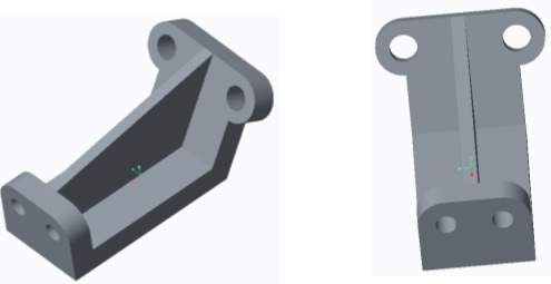
Figure 3 Front and side profile of design
Figure 4 View from all sides of the valveFigure 3 Front and side profile of design
This was design one which shows an angle bracket. This design would have been interesting to mill, but was discarded due to the moulding of this part being complicated and the rib being too thin which could have caused problems later on the project.
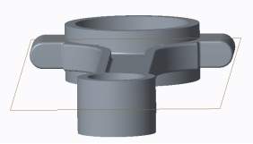
6.2 Butterfly Valve
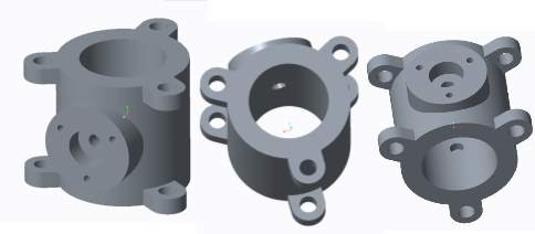
Figure 4 View from all sides of the valve
Figure 6 Completed part design following the dimension aboveFigure 4 View from all sides of the valve
A butterfly valve is a valve that regulates the flow of a fluid in pipe. This design was too common and not original enough to move forward with. But the part design on this was admirable.
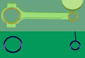
6.3 Connecting Rod
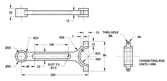 Connecting rod is the key part of car engine parts. Manufacturing fine degrees, inner and outer quality of connecting rods will directly affect the engine performance and level. Because the connecting rod is working at high speed under the fatigue load, so, there is high requirement on the strength of the connecting rod (Spyros, 2016). In addition, due to keep the crankshaft always operate at a high speed in an equilibrium state, so the weight of the connecting rod must also be controlled in a certain range.
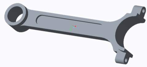
Figure 5 Dimension for connecting rod (Onshape, 2017)
Figure 1 Keyboard cover made through a CNC machine (DARTON Dynamics, 2018)Figure 5 Dimension for connecting rod (Onshape, 2017)
Figure 6 Completed part design following the dimension above
Figure 7 Redesigned connecting rodFigure 6 Completed part design following the dimension above
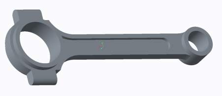 This particular design was initially well liked but due to there being an incomplete feature on the design. It was decided to redesign the part with the now completed feature. The front hole was eliminated so when machining the workpiece would not have to reoriented and can be manufactured on one face.
This design now is the final part design which will be moved forward and will now be prepared for the moulding steps.
Once the model had been successfully verified and extensively checked to be viable, it had to be made suitable for casting and machining. When casting parts, certain surfaces of the design must be angled to allow the model to be extracted from the mould conveniently and at no danger to the structure of the design. Draft angles will be integrated into the walls of the mould so the opening of the cavity is wider than the base. All design features such as draft angles, moulding rounds, machining allowances, have been featured on the part.
 The draft hinge for all drafts is a plane which cuts through the middle of the model. This plane will also serve as the parting surface for the mould volume creation.

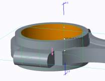
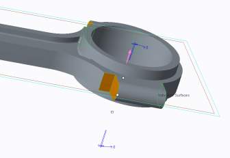
Figure 10 Exterior surface draft of 1 degree
Figure 10 Exterior surface draft of 1 degree
Figure 9 Big hole draft of 1 degree
Figure 9 Big hole draft of 1 degree
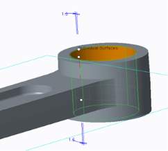 Figure 9 shows the draft angle placed on the main body of the design. This angle will allow the main body to be ejected more easily than if no draft angle were placed. These angled surfaces must be placed throughout the design as many parts must be removed simply from the mould. Draft angles were added to all features on the model that would need aid in removal from the mould or that required subsequent machining. The draft angle was chosen to be 1 degree for most features. Some features that were at risk of having ejection problems have higher draft angles.
Figure 11 Small hole draft of 1.5 degree
Figure 11 Small hole draft of 1.5 degree
 The negative side of using larger draft angles is that it can substantially weaken the model if used in a place of the design that has little material present. That is the reason 1 degree was used on most features.
Figure 13 Edge draft of 3 degrees
Figure 13 Edge draft of 3 degrees
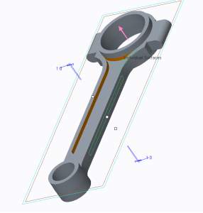
Figure 12 Interior edge draft of 1 degree
Figure 12 Interior edge draft of 1 degree
Sharp corners produce high-stress concentration, which can result in weaker parts, and also hinder material flow is also hindered. Rounded corners have reduced stress concentrations and enhanced material flow (Proto Labs, 2017).
Therefore, a round of radius of 1mm has been added to internal and external corners
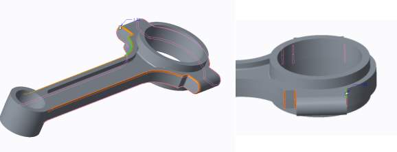
Figure 14 Moulding rounds shown on the edge
Figure 14 Moulding rounds shown on the edge
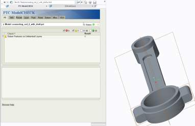
Additional model accuracy checks were carried out to confirm the workpiece was ready to be produced. These checks included going back and ensuring that no buried features had formed, as this can have a negative effect later on in the project. A buried feature is one that is entirely surrounded by or enclosed within other features. Further checks were made for undercuts or traps in respect for the parting surface to ensure easy ejection of the moulded part.
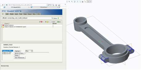 The check revealed 3 buried features caused by rounds created for to eliminate sharp edges.
Figure 15 Feature 1
Figure 15 Feature 1
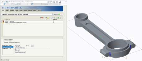
Figure 16 Feature 2
Figure 16 Feature 2
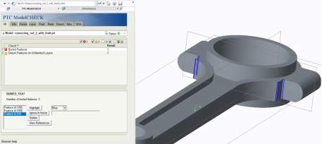
Figure 17 Feature 3
Figure 17 Feature 3
 The issue with rounds causing the buried features has been fixed by redesigning the rounds. Buried fixtures can be dangerous for many reasons including the fact that trying to modify or redefine children of buried features can be difficult causing unexpected feature failures, the model will take longer to regenerate than it should because of the extra features and lastly the file size will also be larger than necessary.
Figure 18 shows the model check and as can be seen, no buried features are on the model. The other warnings, whilst helpful, do not impact the future of the project in such a way as buried features would have, and therefore they can be ignored.
Figure 18 Shows no buried features
Figure 18 Shows no buried features
7.1 Enabling absolute accuracy
 Model accuracy is the precision with which the software creates the geometry. For example, model accuracy determines such characteristics as how finely the software tessellates the model’s curves. A finely tessellated curve is a smoother curve, whereas a coarsely tessellated curve would give the appearance of a series of straight lines that approximate the shape of the curve.
Figure 19 Set absolute accuracy to 0.0024mm
Figure 19 Set absolute accuracy to 0.0024mm
With all necessary checks completed, the reference model was imported into the mould cavity module.
Now the workpiece could be designed for the model. This was created in a similar way to normal modelling in Creo 3.0, by using the sketch and extrude tool to create a block around the model. A simple rectangular block, was created to be roughly three times the size of the models overall dimensions. This extra space is necessary as a smaller workpiece may endanger the structure of the model when being removed from the mould. Figure 20 shows the final workpiece extrusion around the model.
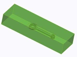 A workpiece around the design model, which will be the main mould block volume enclosing the reference part, was created. The work piece is a model block created around the design model representing the material from which the mould will be machined.
Figure 20 the workpiece is approximately 3 time the size of the model
Figure 20 the workpiece is approximately 3 time the size of the model
 Once the workpiece was designed, parting surfaces had to be assigned. The parting line is the location where the two halves of the mould meet. The selection of the parting line is important for both functional and cosmetic reasons. Once a parting surface was created it will be used split the mould block.
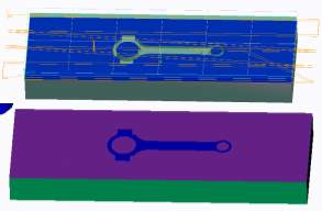
With the parting surfaces being chosen, the workpiece was split into two separate models. At this stage the mould volumes are collections of surfaces and quilts. Consequently, they need to be turned into solid model parts.
Figure 21 Extracted mould top and bottom volumes from the workpiece
Figure 21 Extracted mould top and bottom volumes from the workpiece
8.1 Draft check
Draft angles were then checked on the mould volumes to confirm that the mould can be released easily after casting. The draft checks were carried out on the mould as these are the parts that will be pulled apart from the model
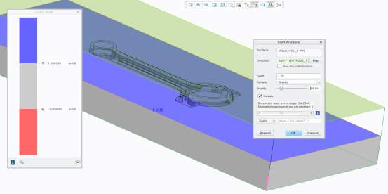 The new mould part cavities were inspected with draft check to ensure that the moulded parts could be ejected without any problems.
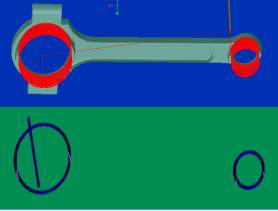
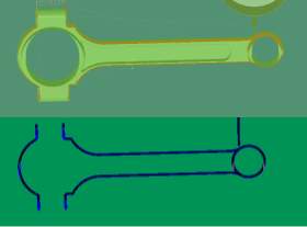
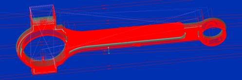
Figure 22 Wireframe view showing computed draft angle check results for MOLD_VOL_1
The draft checks were carried out on the mould as these are the parts that will be pulled apart from the model. The draft check found the drafts placed were working since the colour blue indicated there is a draft of 1 degree present as shown in Figure 22 & 23
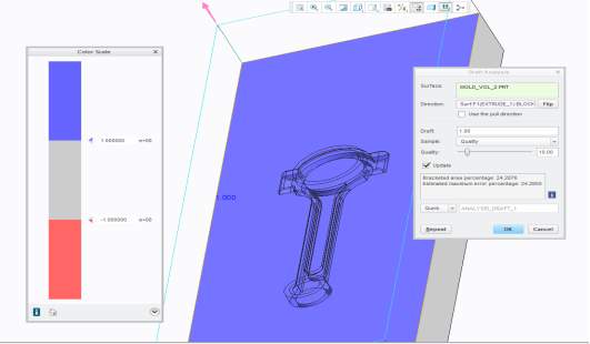
Figure 23 Wireframe view showing computed draft angle check results for MOLD_VOL_2
Figure 23 Wireframe view showing computed draft angle check results for MOLD_VOL_2
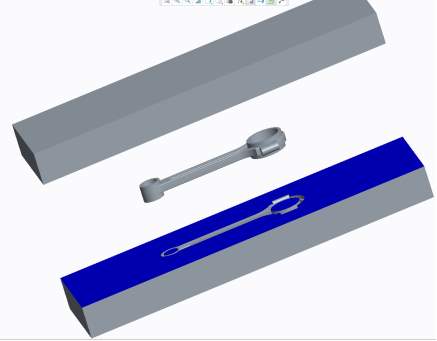 Simulation of opened mould parts:
Figure 24 Mould open with reference part show
Figure 24 Mould open with reference part show
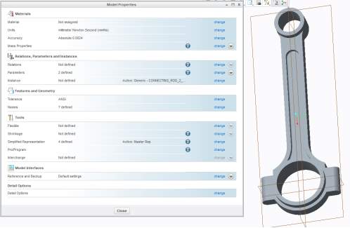
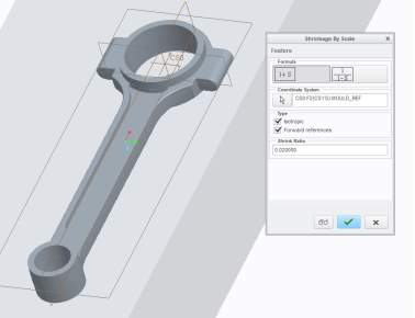 The final part of creating the workpiece was to apply appropriate shrinkage to the model. When die casting, the part normally shrinks afters it’s cooled so it deviates from the original specification. In order to rectify this problem, the mould is made slightly bigger than the original dimension in order to compensate for the shrinkage. Thus, a shrinkage value is used to scale up the dimension of the original value. The amount of shrinkage that occurs depends on the material being used. Different materials have different values but in this particularly project Steel is used as the material which has a shrinkage allowance from 1.5 to 2%. Therefore, the pattern makers shrink ratio used at this stage was 2% (0.02) (Escarraga, 2014).
Figure 25 Shrinkage being applied to the model
Figure 25 Shrinkage being applied to the model
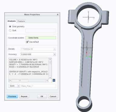
A test shot was created to see if the mould came out as desired and to also see if the shrinkage worked. The material assigned was H13 tool steel with a density of 7750 kg/
m3.
This makes the calculated mass of this part as 0.63 kg.
Figure 26 Mass properties of test shot
Figure 26 Mass properties of test shot
Creo Manufacture is a module within the Creo application which enables the creation of machining tool paths (milling, turning, EDM) and can run a virtual reality machining simulation to check the effectiveness of the machining strategy. With these simulations a workpiece can be manufactured to a 3D model and can process and transfer the information to a machine tool for actual manufacture. Creo can also determine the machining time for any operation no matter how complex the tool paths.
To prepare for manufacturing, a new Creo subdirectory was made and both the mould volume model from the moulding stage was copied over to this CAM folder.
After the mould volume was imported to serve as the reference model. The imported reference is the target for the machining process.
The next step now would be now to create a workpiece. The workpiece is created as a part to represent the stock material, which will be modified by a series of machining sequences When the sequences are complete a representation of the reference model will be left which will be tool for die casting.
The surfaces of the workpiece are displayed in translucent green as shown above. 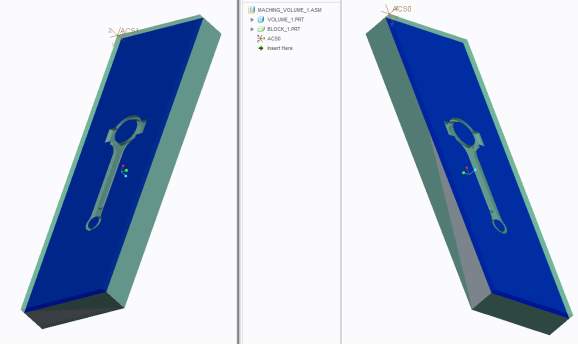 After this stage the next step is to define an operation which will state the machine type and machine coordinate system.
Figure 27 Volume 1 & 2 with completed workpiece extrusion
Figure 27 Volume 1 & 2 with completed workpiece extrusion
For this project, a 3 axis CNC mill will be the machine type. Setting the correct machine coordinate system is critical. In 3 axis NC milling the cutting tool is constrained such that the tool axis remains aligned and parallel to the Z axis. The correct orientation of the Z axis is critical, so the coordinate system used is z-up, x-across and y-away.
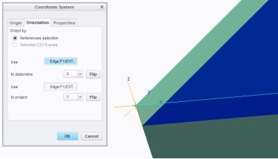
Figure 28 Final coordinate system setup for both volumes.
Figure 28 Final coordinate system setup for both volumes.
Now the operation has been defined. Before starting any machining operation, a process plan is needed which establishes which process and parameters to use to convert a part from its initial form to its final form.
A process plan was created which specified the machining strategy for each workpiece surface and the tool to use to create the cut.
| Operation | Tool Operation | Tool used | Tool Diameter | Tool No. | Part Feature |
| 1 | Face Milling | End Mill | 100 | 1 | Top face |
| 2 | Surface Milling | End Mill | 2.5 | 2 | Large slot and small slot |
| 3 | Profile Milling | End Mill | 2.5 | 2 | Profile of large and small slot |
| 4 | Surface Milling | End Mill | 2.5 | 2 | Inside area |
| 5 | Profile Milling | End Mill | 2.5 | 2 | Profile of middle feature |
| 6 | Face Milling | End Mill | 2.5 | 2 | Top of middle feature |
| 7 | Surface Milling | Ball Mill | 3 | 3 | Outer round feature |
| 8 | Profile Milling | Ball Mill | 1 | 4 | Exterior round |
| 9 | Profile Milling | End Mill | 2.5 | 2 | Side walls |
The plan outlined is for both volumes of the mould to have the same machining strategy since both cavities are the same, this is due to both sides of the connecting rod being identical. This will ensure when post processing the CNC programme output for the G-code commands won’t have to vary greatly. Which will save on labour and will make the process more cost effective.
A prerequisite necessary in the creation of manufacturing data within a CAM module is to decide on suitable cutting tools (material and type) to be used for the actual machining elements. Additionally, calculation of the spindle rpm (speed) and feed rate to be applied to each tool is also required. This data is important since Creo makes use of this information for the determination of the sequence time.
9.1 Cutting Tools
The cutting tools used in these operations are the End mill and Ball end mill. Only two different cutting tools were needed as there are not any complex cuts featured in the workpiece.
End Mills are used for making shapes and holes in a workpiece during milling, profiling, contouring, slotting, counter boring, drilling and reaming applications. They are designed with cutting teeth on the face and edge of the body and can be used to cut a variety of materials in several directions. (Tech Essentials, 2018)
Ball end mills are used for drilling shallow holes, slotting a channel where a flat bottom is not required or most commonly used to produce multi-dimensional contours in moulds or dies (Regal CT, 2016).
9.1.1 Flute Type
Flutes feature grooves that are cut into the body of the tool. A higher number of flutes increases the strength of the tool and reduces space or chip flow. End mills with less flutes on the cutting edge will have more chip space, while end mills with more flutes will be able to be used on harder cutting materials.
For this machining operation 4 flute end mills were used which allows for faster feed rates, but due to the reduced flute space, chip removal may be a problem. They produce a much finer finish than two and three flute tools.
9.1.2 Tool material
The tools listed in these operation uses High speed steel (HSS) as the cutting tool material.
HSS was used because it provides good wear resistance and costs less than cobalt or carbide end mills. HSS is used for general-purpose milling of both ferrous and nonferrous materials
9.2 Cutting parameters
In metal cutting, various cutting parameters like cutting speed, feed rate, depth of cut, tool material, work material etc. are involved. In this operation only the following is used;
| CS – Cutting speed (m/min) | n – Number of teeth/flutes |
| N – Spindle speed (rpm) | Dt – Diameter of tool (mm) |
| Ft – Feed per tooth (mm) | Fa – Cut feed (mm/min) |
Table 2 Abbreviations used within the formulas for the equations
- Cutting speed and spindle speed
Cutting speed is the relative speed at which the tool passes through the work material and removes metal. It is normally expressed in meters per minute. The higher the cutting speed, the better the productivity. For every work material and tool material combination, there is always an ideal cutting speed available.
Spindle speed is expressed in RPM (revolutions per minute). It is derived based on the cutting speed and the work diameter cut (in case of turning/ boring) or tool diameter (in case of drilling/ milling). All cutting speed and feed rate data are taken from (Ivan Popov,2011)
The equation for spindle speed is derived from the equation for cutting speed:
CS=N×π×Dt1000
Spindle speed:
N=CS×1000π×Dt
- Feed rates
The relative speed at which the tool is linearly traversed over the workpiece to remove the material. This is calculated using the flowing equation
fa=ft×N×n
| Material | Milling (mm/tooth) |
| Steel | 0.1 – 0.2 |
| Stainless steel | 0.1 – 0.18 |
The feed rate per tooth(Ft) is tabulated (mm/tooth) and is related to the amount of material each tooth removes during a revolution.
- Depth of cut
It indicates how much the tool digs into the component (in mm) to remove material in the current pass. In other words, the thickness of material removed in single motion.
| Milling (mm/tooth) | |
| Depth of cut (mm) | 0.5 – 1.5 |
Table 4 Recommended DOC values
- Step over
Step over is the distance the tool moves over between subsequent passes. The step over value (along with tool size) will determine whether the model has a smooth finish, or tooling marks are visible. It will also directly impact cutting time. Models with a smaller step over take longer to cut. In this operation the step over value used was 10% of tool diameter.
9.3 Machining parameters
| Tool | Tool No. | Operation No. | No. of Flutes | Dt | CS | Fa | Ft | N |
| End Mill | 1 | 1 | 4 | 100 | 40 | 51 | 0.1 | 127 |
| End Mill | 2 | 2,3,4,5,6 & 9 | 4 | 2.5 | 40 | 2037 | 0.1 | 5093 |
| Ball Mill | 3 | 7 | 4 | 3 | 40 | 1698 | 0.1 | 4244 |
| Ball Mill | 4 | 8 | 4 | 1 | 40 | 5093 | 0.1 | 12732 |
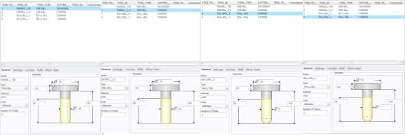 The following shows the one set of cutting tools used for both milling operations:
Figure 29 List of cutting tools used
Figure 8 The plane used for the draft hingeFigure 29 List of cutting tools used
9.4 Tool paths and NC Checks
Creo offers two methods to simulate a machining sequence:
- One is for a cutter axis trace flowing the toolpath along the workpiece.
- The other type of simulation is a virtual reality material removal simulation. This requires a virtual reality simulation software ‘NC Check’ to be selected.
The following shows the machining operations of volume one since the machining sequence for volume 2 are the same, showing both simulations of the cut:
 Sequence 1: Face Milling Sequence 2: Surface Milling
 Sequence 3: Profile Milling Sequence 4: Surface Milling
 Sequence 5: Profile Milling Sequence 6: Face Milling

 Sequence 7: Surface Milling Sequence 8: Profile milling
 Sequence 9: Profile Milling
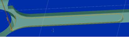
 Final joint operations of all cutter toolpaths:
Figure 30 Volume 1
Figure 30 Volume 1
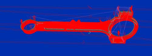
Figure 31 Volume 2
Figure 31 Volume 2
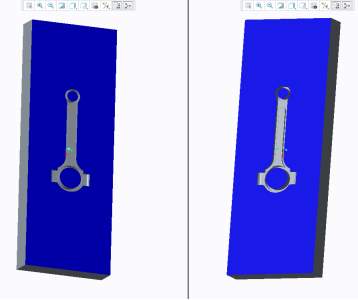
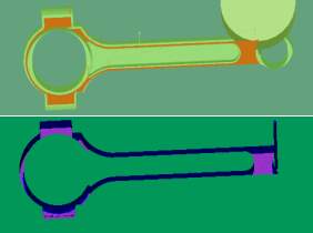
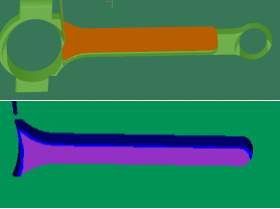
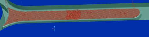
The NC check displays the machining NC Sequence in the colours listed below:
Green = Colour of the workpiece.
Purple = Colour of the reference model where the tool touches the surface.
Blue= Area where represents rough cuts which very given allowances when machining.

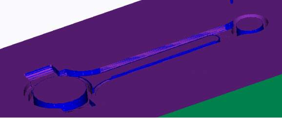 Due to low resolution of the NC software, some correctly finished surfaces did not display fully purple.
Figure 32 NC check for volume 1
Figure 32 NC check for volume 1
Figure 33 NC check for volume 2
Figure 33 NC check for volume 2
| Sequence | Type | Tool | Diameter | Step Depth | Step Over | Machining Time (min.) |
| 1 | Face milling | End mill | 100 | 5 | 50 | 217.87 |
| 2 | Surface milling | End mill | 2.5 | n/a | 0.25 | 1.54 |
| 3 | Profile milling | End mill | 2.5 | 0.5 | n/a | 9.33 |
| 4 | Surface milling | End mill | 2.5 | n/a | 0.25 | 3.28 |
| 5 | Profile milling | End mill | 2.5 | 0.5 | n/a | 1.17 |
| 6 | Face milling | End mill | 2.5 | 0.5 | 0.25 | 97.69 |
| 7 | Surface milling | Ball mill | 3 | n/a | 0.3 | 0.69 |
| 8 | Profile milling | Ball mill | 1 | 0.5 | n/a | 1.1 |
| 9 | Profile milling | End mill | 2.5 | 0.5 | n/a | 5.24 |
| 337.91 |
The following table shows the individual estimated machining sequence time for both milling operations:
| Sequence | Type | Tool | Diameter | Step Depth | Step Over | Machining Time (min.) |
| 1 | Face milling | End mill | 100 | 5 | 50 | 217.87 |
| 2 | Surface milling | End mill | 2.5 | n/a | 0.25 | 1.54 |
| 3 | Profile milling | End mill | 2.5 | 0.5 | n/a | 10.02 |
| 4 | Surface milling | End mill | 2.5 | n/a | 0.25 | 3.31 |
| 5 | Profile milling | End mill | 2.5 | 0.5 | n/a | 1.17 |
| 6 | Face milling | End mill | 2.5 | 0.5 | 0.25 | 97.6 |
| 7 | Surface milling | Ball mill | 3 | n/a | 0.3 | 0.7 |
| 8 | Profile milling | Ball mill | 1 | 0.5 | n/a | 1.22 |
| 9 | Profile milling | End mill | 2.5 | 0.5 | n/a | 5.3 |
| 338.73 |
As shown above the final machining time for volume 1 comes to 337.91 minute and 338.73 minute for volume 2, with a total machining time of 676.64 minutes.
To implement effective time optimisation originally the operations were set up to have minimal tool changes and travel distance between each process. It was then a case of looking at the time each process took and finding ways that their timings could be reduced.
This timing can be further optimised through the changing of sequences and machining parameters such as, spindle speed, cut feed, step over and step depth.
The first area to look at to shave machining time off is to look at cutting speed, which is currently set at 40m/min – was chosen as steel is typically a softer material compared to other materials like Iron, Aluminium and Copper, so a lower range was used. But the 40m/min value would be suitable if the material would have been any other type of steel. The type of steel used in this operation is tool steel. Tool steels are hard and heat and scrape-resistant. They are named tool steels because they are often used to make metal tools, such as stamping, cutting, and mould-making tools. They are also commonly used to make hammers. There are several different grades of steel that can be used for distinct applications (Capital SWI, 2017).
The grade used for this operation is H13 tool steel which is a versatile chromium-molybdenum hot work steel that is widely used in hot work and cold work tooling applications. The hot hardness of H13 resists thermal fatigue cracking which occurs as a result of cyclic heating and cooling in hot work tooling applications. It also has exceptional combination of high toughness and resistance to thermal fatigue cracking (Hudson, 2015).
As a result, the cut speed was increased to 60m/min from 40m/min, it is not advisable to increase it any further as the cutting tools are made from HSS and the cutting tool material also affects the speed. Lower numbers are appropriate for HSS cutting tools, as higher numbers cause reduction in tool life.
The current tabulated feed rate, used to calculate the cut feed, is 0.1mm/tooth by increasing to 0.2mm/tooth. The results should increase the cut feed by a good margin thus decrease the estimated machining time.
As shown in table 6 and 7, the biggest operations contributing to the machining time is face milling. So it was decided to split the that sequence in two, one being a roughing sequence and the latter bring a finishing sequence.
Roughing cuts are typically done at high spindle speed, feed rate and a higher step depth, which are done with a big tool diameter. Finishing cuts are typical done with a smaller cutting tool, where the spindle speed and feed rate are lower and so is the step depth which ensures better surface finish and dimensional accuracy.
The original two face milling sequence are still there but now with higher spindle speed, cut feed and step depth, which are now roughing sequences. The face milling sequences leave a 1mm allowance for the finishing sequence, which is a surface milling sequence. This two sequence also improves the overall surface finish of the top surface. Since before only one sequence was used to mill the top surface. The roughing sequences are also done with coolant option on which should help the cutting tools cope with the higher speeds. This additional finishing step removes all deformations caused by the internal stress from the rough cuts allowing for smoother finish.
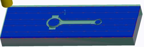
Figure 34 Finishing sequence 1
Figure 35 Finishing sequence 2
Figure 35 Finishing sequence 2
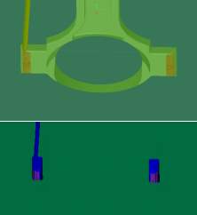
 When looking at the sequences, it was found that a round machining sequence was missing from the original process plan. This sequence was added to the operation using a previous cutting tool.
 Figure 36 Missed feature
| Sequence | Type | Tool | Diameter | Step Depth | Step Over | CS | Fa | Ft | N | Machining Time (min.) |
| 1 | Face milling | End mill | 100 | 5 | 90 | 60 | 300 | 0.2 | 400 | 30.91 |
| 2 | Surface milling | End mill | 50 | n/a | 45 | 60 | 306 | 0.2 | 382 | 12.63 |
| 3 | Surface milling | End mill | 2.5 | n/a | 0.25 | 60 | 6111 | 0.2 | 7639 | 0.57 |
| 4 | Profile milling | End mill | 2.5 | 0.5 | n/a | 60 | 6111 | 0.2 | 7639 | 3.11 |
| 5 | Surface milling | End mill | 2.5 | n/a | 0.25 | 60 | 6111 | 0.2 | 7639 | 1.09 |
| 6 | Profile milling | End mill | 2.5 | 0.5 | n/a | 60 | 6111 | 0.2 | 7639 | 0.39 |
| 7 | Face milling | End mill | 5 | 0.5 | 4.5 | 60 | 3056 | 0.2 | 3820 | 5.06 |
| 8 | Surface milling | End mill | 2.5 | n/a | 0.25 | 60 | 6111 | 0.2 | 7639 | 1.3 |
| 9 | Surface milling | Ball mill | 3 | n/a | 0.3 | 60 | 5093 | 0.2 | 6366 | 0.29 |
| 10 | Profile milling | Ball mill | 1 | 0.5 | n/a | 60 | 15279 | 0.2 | 19099 | 0.42 |
| 11 | Profile milling | End mill | 2.5 | 0.5 | n/a | 60 | 6111 | 0.2 | 7639 | 1.8 |
| 12 | Profile milling | Ball mill | 1 | 0.5 | n/a | 60 | 15279 | 0.2 | 19099 | 0.1 |
| 57.67 |
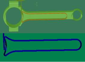
Figure 37 Milling of missed feature
Figure 37 Milling of missed feature
The new optimised process plan is shown in table 8 & 9, with the new spindle speeds and cut feeds plus the addition of the three new machining sequences (shown in blue). The times have been drastically reduced, primary due to the change of the recommended cutting and feed rate.
| Sequence | Type | Tool | Diameter | Step Depth | Step Over | CS | Fa | Ft | N | Machining Time (min.) |
| 1 | Face milling | End mill | 100 | 5 | 90 | 60 | 300 | 0.2 | 400 | 30.91 |
| 2 | Surface milling | End mill | 50 | n/a | 45 | 60 | 306 | 0.2 | 382 | 12.63 |
| 3 | Surface milling | End mill | 2.5 | n/a | 0.25 | 60 | 6111 | 0.2 | 7639 | 0.57 |
| 4 | Profile milling | End mill | 2.5 | 0.5 | n/a | 60 | 6111 | 0.2 | 7639 | 3.34 |
| 5 | Surface milling | End mill | 2.5 | n/a | 0.25 | 60 | 6111 | 0.2 | 7639 | 1.1 |
| 6 | Profile milling | End mill | 2.5 | 0.5 | n/a | 60 | 6111 | 0.2 | 7639 | 0.39 |
| 7 | Face milling | End mill | 5 | 0.5 | 4.5 | 60 | 3056 | 0.2 | 3820 | 4.81 |
| 8 | Surface milling | End mill | 2.5 | n/a | 0.25 | 60 | 6111 | 0.2 | 7639 | 1.39 |
| 9 | Surface milling | Ball mill | 3 | n/a | 0.3 | 60 | 5093 | 0.2 | 6366 | 0.29 |
| 10 | Profile milling | Ball mill | 1 | 0.5 | n/a | 60 | 15279 | 0.2 | 19099 | 0.46 |
| 11 | Profile milling | End mill | 2.5 | 0.5 | n/a | 60 | 6111 | 0.2 | 7639 | 1.8 |
| 12 | Profile milling | Ball mill | 1 | 0.5 | n/a | 60 | 15279 | 0.2 | 19099 | 0.1 |
| 57.79 |
As shown above the final machining time for volume 1 comes down to 57.67 minute and 57.79 minute for volume 2, with a total machining time of 115.46 minutes. The steps taken bellow reduced the original time of 676.64 minutes, to a machining time of 115.46 minutes. This was decrease of around 82%.
When Face Milling, use a cutting tool with a lead angle other than 90 degrees. A 45-degree lead angle face mill will produce a finer finish (CNC Cookbook, 2016) .
The surface finish of a machined part is described, basically, by waviness and roughness. Waviness refers to irregularities on the surface produced by machine or workpiece deflections, vibrations, and other irregularities in the cutting process. Roughness is an ideal effect that results from the geometry of the tool, feed, speed, feed-speed interaction. Roughness must be considered as superimposed feed marks on a wavy surface The final surface roughness, obtained during a practical machining operation, may be considered as the sum of the two independent effects mentioned above. The ideal surface roughness is the best possible finish obtainable for a given set of tool geometry and cutting conditions, if a built-up edge, chatter, inaccuracies in machine tool movements, and other factors were completely eliminated.
Surface roughness occurs from tooth marks left when machining a surface. The tool marks are affected by the different factors that are present in the cutting operation. Some of these factors are: tool geometry, workpiece material, and cutting conditions.
Feed
It has been observed that, in general, surface finish deteriorates when feed rate is increased.
Cutting Speed
Cutting speed is another factor of great importance in the cutting process. It takes direct action on chip formation, forces, and temperature; therefore, the kind of chip obtained depends on the cutting speed, and the kind of chip formed affects surface finish. Cutting forces first increase with increasing cutting speed up to a maximum value, then decrease with a further increase in cutting speed, tending to become constant at high cutting speeds.
Depth of Cut
Investigations on the effect of depth of cut on surface finish indicate that as depth of cut increases, surface roughness also increases when operating at low speeds; the contrary occurs when operating at higher speeds.
Tool Material
It has been observed that surface roughness varies with tool material The key to producing better surface finish with any tool is the wear resistance at high cutting speed. High speed steel produces good surface finish when moderate cutting speeds are used.
Number of Teeth on the Cutter
One important factor, affecting cutting conditions in milling operations, is the number of teeth on the cutter. Tool life is a function of the number of teeth on the cutter. The tool life of the cutter was found to decrease as the number of teeth on the cutter increases. The temperature on the cutter body, and on the workpiece, increases as the number of teeth on the cutter increases found that in face milling, a cutter with more teeth produces a better finish, and for peripheral milling, better surface finish is obtained with a greater number of teeth.
Step over
One of the fundamental parameters of any CNC machining, and 3D machining in particular, is the stopover. Scallops are the ridges left behind from the cutter stepping over in X or Y to cut the next pass. A Ball Mill will always leave a small scallop. The size of that scallop can be specified as the scallop height (Grzesek, 2014).
To further understand the correlation between scallop height and step over.
Conclusion
can u write something here for me, I’m running out of time
Arias, E. R. (1983). ANALYSIS OF SURFACE ROUGHNESS. Retrieved from https://ttu-ir.tdl.org/ttu-ir/bitstream/handle/2346/11712/31295003383329.pdf;sequence=1
CAD Video Tutorials. (2017, July 18). Learn Onshape – Project 10 – Connecting Rod. Retrieved from Youtube: https://www.youtube.com/watch?v=BoOY3atV6qU
Capital SWI. (2017). DIFFERENT TYPES OF STEEL. Retrieved from Capital Steel & Wire, Inc: https://www.capitalsteel.net/news/blog/types-of-steel
CNC Cookbook. (2016). Complete Guide to Surface Finish Symbols, Charts, RA, RZ, Measurements, and Callouts. Retrieved from CNC Cookbook: https://www.cnccookbook.com/surface-finish-chart-symbols-measure-calculators/
DARTON Dynamics. (2018). DATRON MLCUBE. Retrieved from Darton: https://www.datron.com/cnc-machine-products/mlcube.php
Ebay. (2018, August 31). New Geared Head Variable Speed spindle Square Column CNC Milling Machine. Retrieved from Ebay: https://www.ebay.com/itm/New-Geared-Head-Variable-Speed-spindle-Square-Column-CNC-Milling-Machine-/322202824741
Escarraga, A. (2014, June 14). Pattern allowances in metal casting. Retrieved from Slide Share: https://www.slideshare.net/AndresEscarraga1/pattern-allowances-in-metal-casting
Grzesek, R. (2014). How to Choose a Stepover. Retrieved from CNC Cookbook: https://www.cnccookbook.com/cnc-stepover/
Haas Outlet. (2015, July 28). The Many Uses of CNC Lathe Machines. Retrieved from Haas Factory Outlet: http://www.sircomachinery.com/blog/the-many-uses-of-cnc-lathe-machines/
Hudson. (2015). H13 Tool Steel. Retrieved from Hudson Tool Steel Corporation: https://www.hudsontoolsteel.com/technical-data/steelH3
Laique, M. B. (2017, April 18). How many types of CNC (Computer Numerical Control) machines are there? Retrieved from Quora: https://www.quora.com/How-many-types-of-CNC-Computer-Numerical-Control-machines-are-there
Proto Labs. (2017). Design Essentials for Injection Moulding. Retrieved from Proto Labs: https://www.protolabs.co.uk/resources/design-tips/design-essentials-for-injection-moulding/
Regal CT. (2016). Ball End Mills. Retrieved from Regal Cutting Tools: https://www.regalcuttingtools.com/products/end-mills/ball-end-mills
Riberio, J., Cesar, M., & Lopez, H. (2017). Optimization of machining parameters to improve the surface quality. Procedia Structural Integrity, 355-362. Retrieved from https://www.sciencedirect.com/science/article/pii/S2452321617302950
Ryan, V. (2009). ADVANTAGES AND DISADVANTAGES OF CNC MACHINES. Retrieved from Techonolgy Student: http://www.technologystudent.com/cam/cncman4.htm
Ryan, V. (2009). WHAT DOES CNC MEAN ? Retrieved from Technology Student: http://www.technologystudent.com/cam/cnccut1.html
Singh, B., Kumar, R., & Kumar, R. (2014, September 01). TECHNIQUES USED FOR OPTIMIZATION OF PROCESS PARAMETERS IN MILLING OPERATIONS: LITERATURE REVIEW. International Journal of Advanced Technology in Engineering and Science , 522-526. Retrieved from https://pdfs.semanticscholar.org/eaec/c876bd44fe141ea3577fd31eb2a3f53465b5.pdf
Spyros. (2016). Forged Connecting Rods. Retrieved from CFS Forge: http://www.dropforging.net/forged-connecting-rods.html
Sumu, S. (2017, August 31). Types of cnc machines. Retrieved from SlideShare: http://www.cnc4everyone.com/cnc-machines/the-different-types-of-cnc-machines/
Tech Essentials. (2018). End Mill. Retrieved from MSC: https://www.mscdirect.com/basicsof/end-mills
Thomas. (2018, January). More about CNC Milling. Retrieved June 2018, from https://www.thomasnet.com/about/cnc-milling-51276103.html
Cite This Work
To export a reference to this article please select a referencing stye below:
Related Services
View all


Related Content
All TagsContent relating to: "Manufacturing"
Manufacturing describes the process of using raw materials to produce goods. Manufacturing involves workers making use of heavy machinery, tools, and other resources throughout the process.
Related Articles

DMCA / Removal Request
If you are the original writer of this dissertation and no longer wish to have your work published on the UKDiss.com website then please: