Mechanical Circuit Design for Pacemaker Testing
Info: 7650 words (31 pages) Dissertation
Published: 15th Feb 2022
Tagged: Medical TechnologyCardiology
Contents
Click to expand Contents
Introduction
Problem Statement
Objectives
Literature Review
The Heart
The Right Ventricle
Right ventricle in the cardiac cycle
The Blood
Testing cardiac pacemakers
Pacemaker Technology
Technological Surveillance
Modelling the left ventricle using rapid prototype techniques (Smidden)
A left ventricle stimulator manufactured by 3D printing (Bezerra, 2014)
2.4 Construction of an Artificial Heart Pump Performance Test System (Liu, 2006)
2.5 A naturally shaped silicone ventricle evaluated in a mock circulation loop (Gregory, 2009)
Previous work accomplished
Problems with original prototype
How does the circuit work?
Technological Surveillance
Flow meter
Solenoid Valve
Systematic Design
Objectives
Engineering requirements
Project Development
Hard ventricle (epoxy component)
Conceptual Designs
Using the original equipment
A Pneumatic Re-design
References
Introduction
In 2016, a project was under taken by the Nimbus Research Centre to build a device to emulate how the heart works using mechanical devices. The aim of the project set out by Nimbus was to build a device that could be used for testing new implanted cardiac pacemakers in a cost-effective manner while ensuring the tests carried out accurately determine the reliability of the device before testing on animal models. The Nimbus research centre has developed and built a fluid-mechanical system that simulates the pumping motion of the right ventricle of the heart. The system consists of a diaphragm pump which sends water to a reservoir which contains a flexible silicon membrane, removes water from the tank through an orifice which a pipe is connected to. This effect increases and decreases the pressure in the tank which in turn causes the ventricle to contract and expand. The ventricle is connected to a separate circuit, water ejects out of the ventricle when the pressure is highest in the reservoir and is sent through a valve and pipe which replicates the pulmonary valve and pulmonary artery. When the ventricle expands water from the reservoir is sucked through the pipe and valve which are to mimic the tricuspid valve and left atrium and enters the ventricle and the process is repeated.
The circuit has various problems, these include the flexible membrane does not eject the correct amount of fluid at the end of systole which results in the pressure being too low in the system to have a complete circuit as a non-return valve does not open due to lack of pressure. There are various reasons for these problems including leaks present in the system and energy loss.
The aim of the following project is to evaluate and optimise the current circuit by further developing it.
Problem Statement
Pacemakers currently go through animal testing before being used in humans. This process can be expensive and is invasive on the animals. The aim of this project is to create a mechanical circuit that can be used to test pacemakers or similar cardiovascular devices without having to implant them in a living organism. The main problem that must be overcome is trying to replicate both the environment the pacemaker will be in once implanted and the beating of the heart i.e. a normal cardiac cycle.
Objectives
Research Objectives
- Research into the heart, cardiac cycle, blood.
- Research into pacemaker technology in general and existing methods of how they are tested before being released onto the market.
- Perform research as to whether or not a better method of inflation of the heart can be found as opposed to the existing diaphragm pump.
Design Objectives
- Use systematic design to re-design/minimize the existing mechanical circuit.
- Find an alternative material that can be used for moulding of the artificial heart.
Validation Objectives
- Justify the smaller circuit by showing it is just as good if not better than the original.
- Justify the new material for moulding of the heart component.
Literature Review
The Heart
The heart is a muscular organ about the size of a fist, located just behind and slightly to the left of the breastbone. The heart pumps blood through a vast array of arteries and veins known as the cardiovascular system.
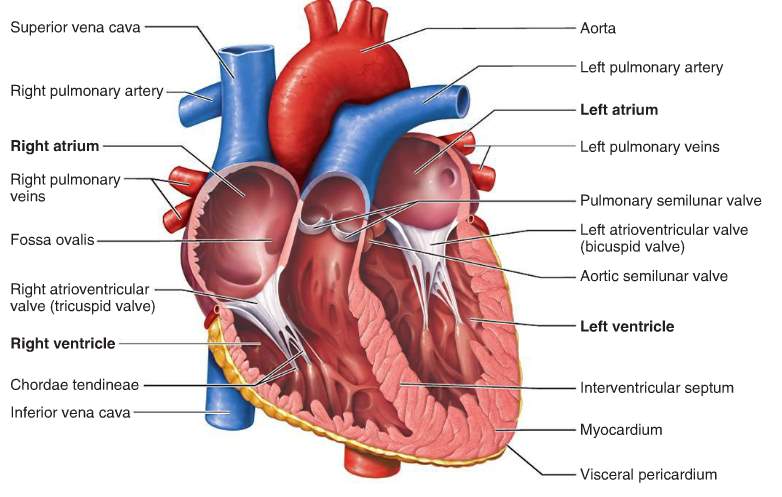
Figure 1 Anatomy of the heart
The heart consists of four chambers:
- The right atrium, which receives blood from the veins and pumps it to the right ventricle.
- The right ventricle, which receives blood from the right atrium and pumps it to the lungs, where it is loaded with oxygen.
- The left atrium, which receives oxygenated blood from the lungs and pumps it to the left ventricle.
- The left ventricle (the strongest chamber), which pumps oxygen-rich blood to the rest of the body. The left ventricle’s vigorous contractions create our blood pressure.
The coronary arteries run along the surface of the heart and provide oxygen-rich blood to the cardiac muscle. Surrounding the heart is a sac called the pericardium. (Matthew Hoffman, 2014)
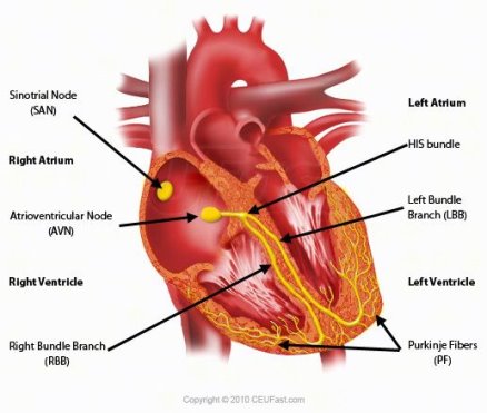
Figure 2 Cardiac Conduction System
The bundle of His is a major part of the electrical system of the heart. Its function is to carry electrical signals from the AV node to the bundle branches.
The electrical system that controls the heartbeat is made up of several parts that signal the heart muscle to contract. The SA node initiates the sequence, causing the atria to contract. The electrical current then travels through the AV node, bundle of His, bundle branches, and Purkinje fibres. This causes the ventricles to contract. This cycle repeats and produces a regular heartbeat. (Anon., n.d.)
The Right Ventricle
The right ventricle extends from the right atrium to the apex of the heart. It is the most anteriorly situated chamber of the heart as it is located behind the sternum. The function of the right atrium is to pump de oxygenated blood from the body to the lungs. (vhlab, 2017) The right ventricle has a complex shape, if viewed from the frontal aspect it is triangular but is crescent shaped from the apex. Compared to the left ventricle the wall of the right ventricle is thinner and ranges from 3mm to 5mm in thickness. The normal right ventricle is accustomed to a low pulmonary resistance therefore normal right ventricle pressure is low. (Lang, 2006)
In figure three below the right ventricle (RV) and right ventricle output tract (RVOT) dimensions can be seen for a normal heart and hearts that have abnormalities.
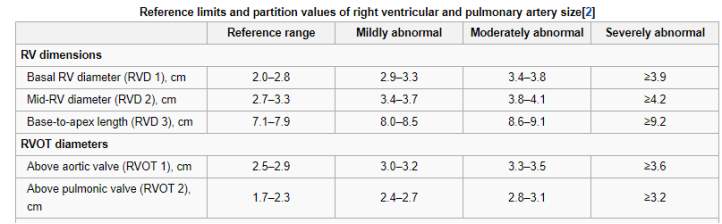
Figure 3 Dimensions of the right ventricle and right ventricle output tract (Lang, 2006)
Table two below shows the values of the flow in the right ventricle. End systolic volume is defined as the volume of blood in the ventricle at the beginning of filling and end of contraction while end diastolic volume is the volume of blood in the ventricle just before systole. Stroke volume is the volume pumped per beat, it is usually referred to the left ventricle but can apply to both. The ejection fraction is the measurement of the fraction of blood pumped from the ventricle with each heartbeat. Cardiac output is the volume of blood pumped by the heart equal to stroke volume * beats per minute.
| Measure | Right Ventricle |
| End diastolic volume | 144 mL (+/- 23mL) |
| End systolic volume | 50 mL (=/- 14 mL) |
| Stroke volume | 94 mL (+/- 15 mL) |
| Ejection fraction | 66% (+/- 6%) |
| Cardiac output | 4 – 8 L/Min |
Table 1: Right ventricle (Pennell, 2016)
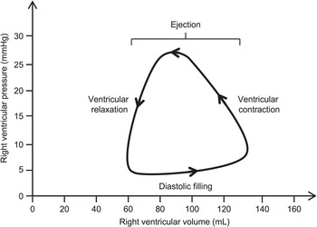
Right ventricle in the cardiac cycle
The right ventricle pressure volume loop which can be seen in figure four, is used to graphically show the function of the right ventricle. The pressure is lowest during diastole when the right atrial pressure exceeds the right ventricle pressure, the tricuspid valve opens and the ventricle will begin to fill with blood. The next stage is ventricular contraction also known as the isovolumetric contraction phase, the right ventricle pressure exceeds the right atrium pressure. The tricuspid valve closes. The third stage corresponds to the opening of the pulmonary valve and the ventricular ejection. The pressure is highest at this stage at ~25 mmHg. At the final stage, ventricular ejection ceases and the pulmonary valve closes. This stage is also known as isovolumetric relaxation. (Friedman, 2018)
The Blood
Blood is a specialized body fluid. It has four main components: plasma, red blood cells, white blood cells, and platelets. Blood has many different functions, including:
- transporting oxygen and nutrients to the lungs and tissues
- forming blood clots to prevent excess blood loss
- carrying cells and antibodies that fight infection
- bringing waste products to the kidneys and liver, which filter and clean the blood
- regulating body temperature
The blood that runs through the veins, arteries, and capillaries is known as whole blood, a mixture of about 55 percent plasma and 45 percent blood cells. (Hematology, 2018)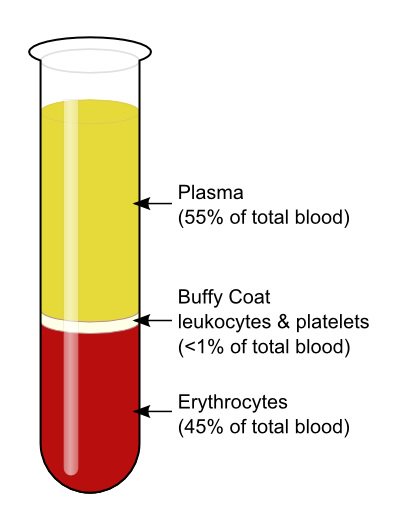
Figure 4 Components of the blood
- Plasma: The liquid component of the blood which carries nutrients and all blood cells.
- Red blood cells (erythrocytes): Carries oxygen from the lungs to the rest of the body.
- White blood cells (leukocytes): Fight infection and aid in the immune process. Types of white blood cells include:
- Lymphocytes
- Monocytes
- Eosinophils
- Basophils
- Neutrophils
- Platelets (thrombocytes): Clot the blood. (Berry, 2018)
It should be noted that human blood is a non-Newtonian fluid. It has a viscosity range of 3.6*10-3 -4*10-3.
Testing cardiac pacemakers
When a new cardiac device such as a pacemaker is developed it must go through extensive testing before clinical trials can be carried out. Typically, an engineer or physician inventor conceives a solution to a clinical challenge and develops a prototype device. Initial bench and animal testing would be performed before further development. Engineers and physicians would work closely together to bring an idea through the ‘design, build, test and redesign cycle’ of bench and animal testing. The preclinical stage can take up to 3 years depending on the device and can cost up to twenty million before the device is ready for clinical testing. (Aaron V. Kaplan, 2004)
The FDA have strict guidelines on testing of cardiac pacemakers, their invitro testing includes electrical characterisation, environmental factors i.e. mechanical shock, vibrations and temperature, battery testing, interference (electromagnetic magnetic, defibrillation) and finally program verification. Once these tests are complete, the next step is in-vivo testing. (Dahrn, 2009)
Animal testing is very expensive, housing a marmoset for a year costs £4000. A larger monkey would cost around £18,000, not including the cost of testing, veterinary costs etc. (Anon., 2017)
Pacemaker Technology
A pacemaker is an electrically-charged medical device that is implanted under the skin in your chest in an attempt to correct cardiac arrhythmias (irregular heartbeats).
A modern pacemaker mainly consists of two parts. One part, called the pulse generator, contains the battery and the electronics that control the heartbeat. The other part is one or more leads that send electrical signals to your heart. Pacemakers generally treat two types of arrhythmias:
- tachycardia, a heartbeat that’s too fast
- bradycardia, a heartbeat that’s too slow (Krans, 2017)
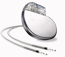
Figure 5 Pacemaker
The original and overall aim of this project was to create a fluid mechanical system that can run simulations on pacemakers without having to implant them in an animal. This is outside the scope of this iteration of the project. The main aim of this project is to improve upon the technology already present in the circuit, therefore, pacemakers will not be seen anywhere in this project.
Technological Surveillance
Modelling the left ventricle using rapid prototype techniques (Smidden, n.d.)
The following journal discusses a new design for a model of the left ventricle in which left ventricle wall deformation can be controlled.
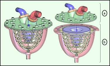
Figure 7 CAD model of left ventricle
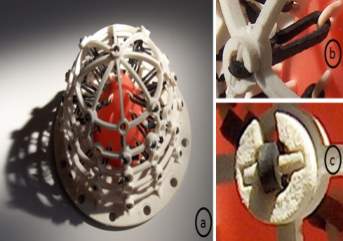
Figure 6: 3D CAD model of left ventricle model
The left ventricle model in this article was created using a combination of three different rapid prototype techniques. The techniques used were vacuum casting, stereolithography and selective laser sintering.
The designed ventricle consists of two main portions, the valve housing and the ventricle part. The ventricle part mimics contraction while the valve housing contains the two heart valves. The ventricle part is an inner thin membrane which is considered as the analogues of the heart, second a middle layer that has flexible bars to represent the myocardium to account for ventricle contraction to control and to control the deformation. Finally, an exterior shell covering the parts represents the epicardium.
Figure 8: Prototype of left ventricle
The thin membrane is modelled from a flexible Polyurethane. A sealing ring is used to prevent leaking between the region with the flexible bars and the cavity. The flexible bars connect the inner and outer layers. The bars needed to be flexible to allow deformation but still enough to control the wall deformation. The outer shell functions as an exterior box. The pump is connected though the outer frame under the apex section, a piston pump is used in this paper.
The materials used to create the ventricle include, epoxy by SLA to build the external shell, polyamide by SLS to construct the supporting frame and polyurethane to produce the flexible membrane.
Once the model was built, it was actuated using a piston pump and connected to a pumped hydraulic model of the vascular system.
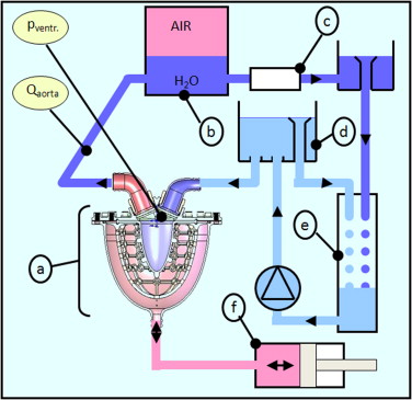
Figure 9: Fluid circuit
A left ventricle stimulator manufactured by 3D printing (Bezerra, 2014)
In the following journal, a pulsatile pump is developed to stimulate the left ventricle in a cardiovascular stimulator without creating negative pressure. The circuit developed consisted of a left ventricle stimulator, fluid reservoir, flow sensor, three pressure sensors and a peripheral resistance. Each part was connected using flexible tubing.
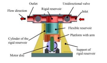
Figure 10: Final design of left ventricle stimulator
A pulsatile pump with a flexible and rigid reservoir was designed. The flexible diaphragm is used to provide stroke volume while the rigid reservoir is used to obtain end systolic volume. To simulate the left ventricle an open tank is connected to the inlet of the left ventricle stimulator. A DC motor is used to generate pulsatile flow and a pressure of 1.33 Pa was obtained inside the tank. The circuit contained two ball valves that simulate the aortic and mitral valve and which are responsible for unidirectional flow.
Parts for the rigid reservoir, moulds for the fabrication of silicone and the motor disk were manufactured using 3D printing. An issue that was found is that the porosity of the material allowed fluid to seep into the rigid reservoir, to solve this a material with low porosity denominated digital ABS was used instead. Aluminium was used for the motor disks and the flexible reservoir was printed using rubber like material.
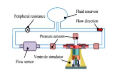
Figure 11: Hybrid circuit developed
Two pressure sensors are present in the circuit, one is located before the ventricle stimulator to measure the left atrium pressure. The other sensor is present after the ventricle stimulator to measure aortic pressure. The final sensor measures the pressure inside the ventricle.
2.4 Construction of an Artificial Heart Pump Performance Test System (Liu, 2006)
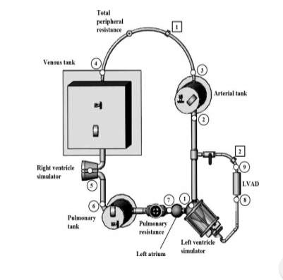
Figure 12: Mock circuit for heart performance test system (Liu, 2006)
The following circuit was designed to stimulate flow/pressure response of the human circulatory system to bench test different versions of rotary left ventricle assist devices (LVAD). The circuit consists of pulsatile right and left cardiac stimulators which are used to stimulate the right and left ventricle pulsatile function.
A semi-ellipsoid shaped silicon diaphragm is encased in a transparent sealed air chamber which forms the fluid chamber of the cardiac stimulators. Check valves are positioned to simulate the mitral and aortic valve, respectively.
A pneumatic control box is used to control the air pressure inside the air chamber of the cardiac simulators. The pneumatic control box supplies pressurised and vacuum air to contact and expand the silicon diaphragm alternatively to stimulate diastole and systole phases of the ventricle. Three airtight tanks, the pulmonary tank, venous tank and arterial tank are used to stimulate the systematic arterial, systematic venous and pulmonary compliances. Each tank has an air valve to adjust the amount of sealed air inside.
To connect all the components in the circuit, tygon tubes are used. A tubing clamp is used to model variation in the system resistance characteristics under different conditions. An artificial heart pump will be connected to the mock circulatory loop, the inlet of the pump is connected to the left ventricle stimulator and the output is connected to the systemic arterial tank.
2.5 A naturally shaped silicone ventricle evaluated in a mock circulation loop (Gregory, 2009)
A left ventricle model was created by taking CT images of the heart throughout the cardiac cycle. The images were processed and the end systolic period was selected to base the model on as it represents the ventricle size at minimal preload. A 3D representation of the ventricle chamber was created using MIMIC software and using a CAD package a negative mould of the ventricle shape was created. The mould was manufactured using ABS plastic. Silicone of shore hardness 15 was used as the material to represent the ventricle due to similar mechanical properties to cardiac muscle. Clear polycarbonate was used to create a pressure chamber surrounding the silicone. The silicone ventricle and pressure chamber were connected to a pre-existing mock circulation. Compressed air was supplied to the pressure chamber surrounding the silicone ventricle to initiate ventricle contractions was effective in producing efficient cardiac ejection. At the bottom of the pressure chamber a clearance fit allowed the insertion of a VAD cannula.
Previous work accomplished
A total artificial heart was designed, the material used to create this heart was a silicone elastomer block. The aim is for the heart to replicate the motion of muscular systems using flexion, extension, bending and twisting.
The chambers of the artificial heart were designed without atriums and therefore consisted of two ventricles and a pneumatically driven expansion chamber which was placed between these ventricles. This allowed for instantaneous pumping from both chambers.
The artificial heart was manufactured using a lost-wax casting process. An injection mould of the designed heart was formed from poly ABS plastic using 3D printing. The voids were then filled with silicon and cured at room temperature for twelve hours. It was then placed in an oven at sixty-five degrees for a full day. The poly ABS plastic was dissolved in acetone which resulted in a single silicone mono block total artificial heart.
The mock circuit consists of two parts, the active and the passive part. The passive part consists of pumps and a bucket its purpose is to simulate the physiological conditions for the right side of the artificial heart. The parts were placed in such a way that a hydrostatic pressure of forty mmHg is applied to the right ventricle of the artificial heart. The active part consists of two pressure-controlled reservoirs which were used to simulate the pulmonary venous pressure and the aortic pressure. The active part simulates the physiological conditions of the left ventricle of the artificial heart.
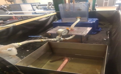
Figure 13 Existing Prototype
The fully artificial heart was then swapped for a redesigned silicone membrane as seen below;
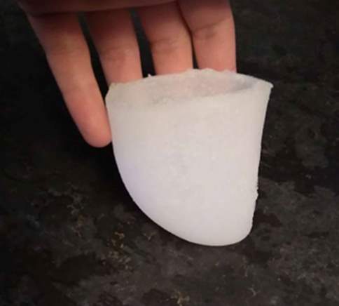
Figure 14 Redesigned Silicon Membrane
Silicon was chosen due to the fact that it has very similar mechanical properties to actual cardiac tissue. The problem with using silicon however, is that it wears away relatively quickly with use. An alternative material with similar mechanical properties may have to be sourced.
The original water tank was also resized for more economy and easier transport of the prototype.
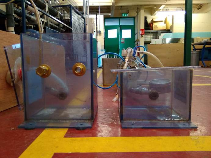
Figure 15 Resized tank compared to a tank similar in size to the original
Problems with original prototype
- One of the main problems discovered when the heart emulator was tested was the difficulty in trying to calculate the pressure being applied to the silicone membrane in the tank. With a pneumatic system using air compression and vacuum being applied to the silicone membrane, the exact pressure in the pressure chamber is unknown.
- When the diaphragm pump was switched on the ventricle immediately began beating and ejecting water. It was noted the tank that contained the silicone ventricle was leaking and water was being lost from the system at a considerable rate.
- The tank used in the circuit is not suitable for the application. The design would require all edges to be sealed. The epoxy piece and silicone membrane would need to be able to be removed if necessary, at current a polycarbonate sheet is bolted to another polycarbonate sheet to connect the epoxy piece and silicone to the circuit. If sealant was used then it would be impossible to remove the parts if anything went wrong.
- The pressure in the tank is unknown due to it changing throughout. Pressure is lost in the pipes due to friction and head loss. If trying to mimic the right ventricle it would be very important to try to mimic the pressure surrounding the cardiac pacemaker, one bar which was the pressure in the inlet pipe used in the previous project is 750 mmHg of mercury while -0.5 bar in the outlet is -375 mmHg, these pressures are considerably greater than the 10 mmHg and 25 mmHg present in the right ventricle. The closer the pressure is to these values the more accurate the system represents the heart.
- The mould which the silicone membrane was casted in contained air bubbles. Placing the epoxy in warm water did expel some of the air. Air bubbles may weaken the membrane fast over time when exposed to pressure due to the air bubbles.
How does the circuit work?
The fluid mechanical circuit consists of a double diaphragm pump, three reservoirs, pipes, pressure gages, two non-return valves and two ball valves.
Compressed air is the power supply for this pump. It contains two chambers with a diaphragm. It pumps the fluid around the circuit and the flowrate can be varied by using a compressor to alter the pressure. The diaphragm pump works at a minimum pressure of 1.4 bar. The pump sends and sucks up 75 ml of water each cycle which is ideal as this matches the stroke volume of the heart. The diaphragm pump is connected to reservoir one which is used to store water. Water is drawn from the reservoir and then passes through the ball valve and enters reservoir two. As the water enters the second reservoir, the ventricle contracts due to the increase in pressure in the system. As the pump removes water from the reservoir a depression is created in the reservoir, causing the ventricle to expand which allows it to receive water.
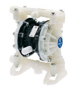
Figure 16 Husky 515 Diaphragm Pump
The first ball valve is left open as the aim in the first iteration of this project was to send 75 ml in 27ms while the second ball valve was fifty percent open to draw 75ml in 53ms.
Two non-return valves were used in the ventricle circuit to replicate the tricuspid and pulmonary valves, when the ventricle contracts water is sent into both pipes, one replicating the pulmonary artery and the other connecting the reservoir which represents the right atrium. In the heart, blood only is ejected into the pulmonary artery but to prevent the water going through the pipe connecting the atrium and tricuspid valve a stop plug is used. The non-return valves have a cracking pressure of 0.35 bar.
Pressure gauges are used to measure the pressure in the pipes. The pressure and flowrate vary throughout the system. This is used to measure the pressure needed to open the non-return valves and the pressure that arrives in the ventricle.
The ventricle consists of two parts, a hard ventricle which is made up of 3D printed parts and a polycarbonate part which were glued together using epoxy. The flexible membrane was moulded by 3D printing the moulds and then using silicon as the material. Silicon was chosen as it has similar mechanical properties to the heart (can mimic expansion and contraction), is waterproof and can be moulded to chosen shape.
The circuit has various problems, the main problem is the lack of pressure produced for the ventricle to eject fluid. Reasons for this include, leaks present in the current design, pressure being lost due to reservoir expanding and contracting when the system is running this results in not enough pressure in the valves in the system.
Technological Surveillance
In this chapter, various different pieces of technology that could be added to the existing circuit in an effort to improve it will be discussed.
Flow meter
A flow meter is an instrument used to measure linear, nonlinear, mass or volumetric flow rate of a liquid or a gas. The first step in flow sensor selection is to determine if the flowrate information should be continuous or totalized, and whether this information is needed locally or remotely. If remotely, should the transmission be analogue, digital, or shared? And, if shared, what is the required (minimum) data-update frequency? Once these questions are answered, an evaluation of the properties and flow characteristics of the process fluid, and of the piping that will accommodate the flow meter, should take place (Anon., n.d.)
In the interest of keeping cost low while still being affective, a rotameter or variable area flow meter could be used. The rotameter is a tapered tube and a float.
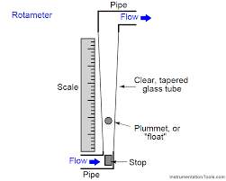
Figure 17 Basic Layout of a Rotameter
It is the most widely used for gases and liquids flow measurement because of its low cost, simplicity, low pressure drop, relatively wide rang ability, and linear output (Anon., n.d.).
Solenoid Valve
One possible way of controlling the pressure and vacuum in the tank is by using a 3-way solenoid valve. A solenoid valve is control unit that is controlled by an electric current through the solenoid. A 3-way solenoid valve has two valve seats and three port connections. One valve is always open, the other valve remains closed when the solenoid is de-energised. When the coil becomes energised, the first valve closes while the second opens (Anon., 2018). The solenoid valve could be controlled by an Arduino, an open-source electronics platform based on easy to use hardware and software. Arduino boards are able to read inputs. This input can be turned into an output i.e. activating a motor. The board can be programmed to in the form of instructions to the microcontroller on the board (Anon., 2017).
Pressure Sensor
Given that the sensor in question will be used to gauge the vacuum within a tank. The type of pressure sensor that will be used in this project is a vacuum gauge. A vacuum gauge is a pressure gauge used to measure pressures lower than the ambient atmospheric pressure, which is set as the zero point, in negative values (e.g.: −15 psig or −760 mmHg equals total vacuum). Most gauges measure pressure relative to atmospheric pressure as the zero point, so this form of reading is simply referred to as “gauge pressure”. However, anything greater than total vacuum is technically a form of pressure. For very accurate readings, especially at very low pressures, a gauge that uses total vacuum as the zero point may be used, giving pressure readings in an absolute scale.
Systematic Design
In this project, a systematic design approach will be used to come up with different concept solutions for the problems in the fluid mechanical circuit. Different sections of the circuit i.e. the flexible membrane, reservoir, and the leaks will be evaluated and the concepts will be narrowed down using the objectives, engineering requirements, metrics and morphological table.
Objectives
- To improve the durability of the flexible membrane by selecting a suitable replacement material and eliminating any leaks.
- To validate the emulator by experimental testing and compare the results to the theoretical values.
Engineering requirements
From the objectives a table of the engineering requirements for the project was created, in order for the circuit to be at its optimal, the values below must be met. The actual values in the table are representative of what the project was able to achieve the last time it was in operation.
| rqmt. # | Importance | Source | Function | Engr. Requirement | Unit of Measure |
Ideal Value | Actual Value | ||
| 1 | High | Heart Physiology | Input | Pressure on the ventricle | mmHg | 25 mmHg | Unknown | ||
| 2 | High | Heart Physiology | Input | Volume in ventricle (Diastole) | mL | 125 mL | 70mL | ||
| 3 | High | Heart Physiology | Output | Ejection volume | mL | 75mL | 35mL | ||
| 4 | High | Heart Physiology | Output | Flowrate | L/min | 5L/min | 5L/min | ||
| 5 | Med | Heart Physiology | Dimensions | Length | Cm | 8 cm | 8.7 cm | ||
| 6 | Med | Heart Physiology | Dimensions | Width | Cm | 3 cm | 4.2 cm | ||
| 7 | Low | Heart Physiology | Dimensions | Thickness | Mm | 4 mm | |||
| 8 | Med | Reservoir size | Dimensions | Length | Mm | 240mm | 240mm | ||
| 9 | Med | Reservoir size | Dimensions | Width | Mm | 190mm | 190mm | ||
| 10 | High | Reservoir size | Dimensions | Height | Mm | 150mm | 250mm | ||
| 11 | High | Reservoir material | Material requirements | Na | Na | Na | Na | ||
| 12 | Med | Blood physiology | Fluid | 40% glycine1 + 60% water | kg/s*m | 3-4(10^3) | 0.9 – 1 | ||
| 14 | Med | Project constraints | Cost | Budget | Euro | Na | |||
| 16 | High | Data acquisition | Record Pressure | mmHg | |||||
| 17 | High | Data acquisition | Record Flowrate | L/min | |||||
Note: The values above are for a healthy heart with a BPM of 70. If this can be met, it should not be difficult to vary the BPM.
Project Development
Hard ventricle (epoxy component)
A design for the mould was created using a computer aided software (Autodesk Inventor). Acetone was used to dissolve the mould. It was decided that the ventricle would be moulded as one solid block and the holes would be bored after. The next item to be considered was that the mould had to have an opening on top to allow the epoxy mixture to be poured in. Finally, a method to clamp the two moulds together was needed. Bolts were used in this design to clamp the moulds together. As can be seen in figure 10, two tabs at both sides of the mould with a 5mm opening to allow a bolt and nut to be inserted to clamp together the mould while the epoxy is curing. The final design can be seen in figure. A cover was created for the mould to ensure no foreign material would enter the mould will the epoxy was curing. The mould itself was 3D printed using ABS plastic. 3D printing allows for the quick fabrication of a 3D product using CAD drawings.
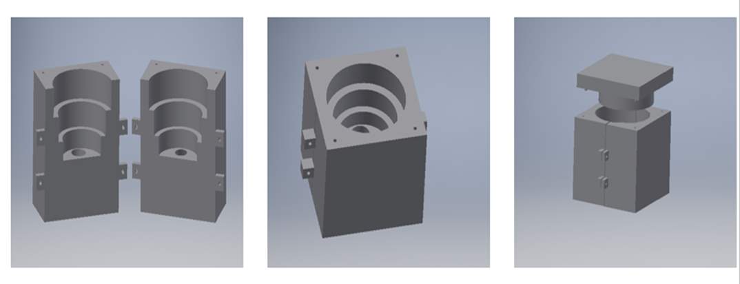
Figure 18 Inventor drawing of the original mould
Epoxy was the material chosen to create the mould. Epoxy is made up of two components, the epoxy resin and the epoxy curing agent. When the resin and curing agent are mixed an inert hard material is formed. Epoxy resin consists of bisphenol and epichlorohydrin. It works on the principal that the reaction between the bisphenol and the epichlorohydrin removes unreacted phenol and acetone and attaches. It is important to choose the correct curing agent for the epoxy as it determines the final properties of the product e.g. dry time, wetting ability etc. The curing agent is made up either amines which are derivatives of ammonia or amides which are derivatives of carboxylic acids. Amine based curing agents are more durable than amide based. Epoxy works due to strong polar bonds it forms with surfaces it comes in contact with. The bond between the surfaces displaces the air. (Nilsmalmgren, 2017)
The epoxy resin and curing solution was carefully added to the mould to ensure no air bubbles were present. The epoxy was left to harden for 24 to 48 hours. Once the process was complete, two holes were bored through the tubes in the ventricle in the workshop to complete the design.
This version of the hard ventricle component performed very well in testing. However, going forward the component itself could be made smaller. Between the pipe connection on top and the silicone membrane there is a 7 cm tube, this could be reduced to approx. 3 cm to allow for quick ejection of water and prevent any water returning to the silicone membrane. SP106 is a fast curing epoxy that was used, a slow curing epoxy will be used in semester two to try and improve the component. The original mould contained air bubbles. To counter act this problem the mould was placed in warm water and this did expel some of the air bubbles but not all of them. Obviously this is not ideal going forward as these air bubbles create areas of weakness in the piece once pressure is applied. When the new mould is left to cure, a method will be devised for allowing it to cure from within a vacuum in an effort to prevent the formation of said air bubbles.
Conceptual Designs
Using the original equipment
This approach would involve the utilisation of all the original equipment. For this approach to work however, the leaks mentioned in the original system would need to be fixed. A flow meter would also be incorporated into the system for an accurate measure of the pressure inside of the tank acting on the silicone membrane.
A Pneumatic Re-design
One of the main problems associated with the testing of the previous deign of the heart emulator is that it was very difficult to calculate the pressure being applied to the silicone membrane in the tank. With a pneumatic system using air compression and vacuum being applied to the silicone membrane, the exact pressure in the pressure chamber would be known. Unlike the hydraulic system, all the parameters would be known in the system and accurate theoretical predictions could be made. A provisional design was made for a pneumatic system that due to time constraints, did not come to fruition last year. This option will now be investigated further.
The pressure chamber must have two connections, one for air compression and the other for vacuum suction. A strong durable material able to withstand different pressures and is permeable. After research into pressure and vacuum chambers common materials found to be used include glass, steel, aluminium, acrylic etc. (Danielson, 2018). The pressure/vacuum chamber is to be designed in three separate parts. The bottom piece which can be seen in figure 51, will be manufactured using aluminium, it will contain two ports one to be connected to an air compressor and the other to a vacuum pump.
The second part which can be seen in figure 50, is a clear acrylic plastic tank, acrylic plastic is often used as a material for vacuum and pressure chambers, in this project the contraction and expansion of the silicone membrane is favourable
Finally, for the top of the chamber, an aluminium piece will be manufactured and attached to the acrylic body, the epoxy piece can be attached to the top piece using a strong adhesive such as epoxy. In this design, the dimensions of the epoxy piece would be reduced. The silicone membrane from the current system can be still used. This still requires two connections to the membrane, one for water entering and the other for ejected water. The cover can be designed to place the epoxy piece in it. An advantage to this system, is the exact pressures of the right ventricle can be applied, if successful in emulating the ventricle the correct pressure is applied, giving more accurate results in the testing of cardiac pacemakers. (Hawksby, 2017)
References
Aaron V. Kaplan, D. S. B. J. J. S. D. A. F. M. S. D. J. T. J. F. R. E. K. M. B. L., 2004. Medical Device Development From prototype to regulatory approval. pp. Pages 3068-3072.
Anon., 2017. Hobbytronics. [Online] Available at: www.hobbytronics.com
Anon., 2017. TheGuardian. [Online].
Anon., 2018. Tameson. [Online].
Anon., n.d. medmovie.com. [Online] Available at: www.medmovie.com/library_id/7556/topic/cvml_0016i/
Anon., n.d. Omega, A Spectris Company. [Online] Available at: https://www.omega.com/prodinfo/flowmeters.html [Accessed November 2018].
Berry, J. P. A., 2018. urmc.rochester.edu. [Online] Available at: www.urmc.rochester.edu/encyclopedia/content
Bezerra, L. P., 2014. A left heart ventricle simulator manufactured by 3D printing. IFAC proceedings volumes, pp. 11599-11604.
Dahrn, D. F., 2009. FDA. [Online].
Danielson, P., 2018. Choosing the Right Vacuum Materials. A journal of Practical and Useful Vacuum Technology.
Friedman, B. J., 2018. Characterization of the human right ventricular pressure-volume relation: Effect of dobutamine and right coronary artery stenosis. Journal of the American College of Cardiology, pp. 999-1005.
Gregory, S., 2009. A naturally shaped silicone ventricle evaluated in a mock circulation loop. Journal of medical engineering and technology, pp. 185-191.
Hawksby, K., 2017. Design and Development of a Heart Emulator , s.l.: s.n.
Hematology, A. S. o., 2018. In: Hematology, the ASH Education Program Book. s.l.:s.n.
Krans, B., 2017. www.healthline.com. [Online] Available at: https://www.healthline.com/health/heart-pacemaker
Lang, R. M., 2006. Recommendations for chamber quantification. Recommendations for chamber quantification, pp. 79-108.
Liu, Y., 2006. Construction of an artificial heart pump performance test system. pp. 152-160.
Matthew Hoffman, M., 2014. WebMD.com/heart. [Online] Available at: www.webmd.com/heart/picture-of-the-heart#1
Nilsmalmgren, 2017. [Online].
Pennell, A. M. M. S. K. P. M. K. D. J., 2016. European heart journal. Right ventricle systolic and diastolic function normalised to age, gender and body surface area from steady-state free precession cardiovascular magnetic resonance, 27(23), p. 2879–2888..
Smidden, V. D., n.d. Modelling the left ventricle using rapid prototyping methods.
vhlab, 2017. vhlab. [Online] Available at: www.vhlab.umn.edu/atlas/right-ventricle/index.shtml
Cite This Work
To export a reference to this article please select a referencing stye below:
Related Services
View all


Related Content
All TagsContent relating to: "Cardiology"
Cardiology is a medical speciality that deals with diseases, the function, and defects of the heart and cardiovascular system such as valvular heart disease, coronary heart disease, heart failure and others. Cardiologists diagnose and treat patients with such conditions.
Related Articles
DMCA / Removal Request
If you are the original writer of this dissertation and no longer wish to have your work published on the UKDiss.com website then please: