Shape Memory Alloy Actuator
Info: 14070 words (56 pages) Dissertation
Published: 16th Dec 2019
Tagged: Engineering
ABSTRACT
Need modification
With the increased emphasis on both reliability and multifunctionality in the aerospace industry, active materials are fast becoming an enabling technology capturing the attention of an increasing number of engineers and scientists worldwide. This article reviews the class of active materials known as Shape Memory Alloys (SMAs), especially as implemented in aerospace applications. To begin, a general overview of shape memory alloys is provided. The useful properties and engineering effects of SMAs are described and the methods in which these may be utilized are discussed. A review of past and present aerospace applications is presented. The discussion addresses applications for both atmospheric earth flight as well as space flight. To complete the discussion, SMA design challenges and methodologies are addressed and the future of the field is examined.
Shape memory alloys (SMAs) are a unique class of metallic materials with the ability to recover their original shape at certain characteristic temperatures (shape memory effect), even under high applied loads and large inelastic deformations, or to undergo large strains without plastic deformation or failure (super-elasticity). In this review, we describe the key features of SMAs, their constitutive models and their properties. We also review the fatigue behaviour of SMAs and some methods adopted to remove or reduce its undesirable effects. SMAs have been used in a wide variety of applications in different fields. In this review, we focus on the use of shape memory alloys in the context of morphing aircraft, with emphasis on variable twist and camber, and on actuation bandwidth and reduction of power consumption. These applications prove particularly challenging because novel configurations are adopted to maximize integration and effectiveness of SMAs, which play the role of an actuator (using the shape memory effect), often combined with structural, load-carrying capabilities. Iterative and multi-disciplinary modelling is therefore necessary due to the fluid–structure interaction combined with the nonlinear behaviour of SMAs.
TABLE OF CONTENTS
2.4 Challenges face to adapt material in engineering
2.4.1 Low Controllability and accuracy
2.4.3 Durability and reliability
2.5 Advantages and disadvantages of SMA
2.6 Shape memory alloy applications
2.6.1 Automotive Applications – EAGLE (Electrically Actuated antiglare rear-view mirror)
2.6.2 Aerospace Application – Boeing’s variable geometry chevron
2.6.3 Robotic Application – Prosthetic hand
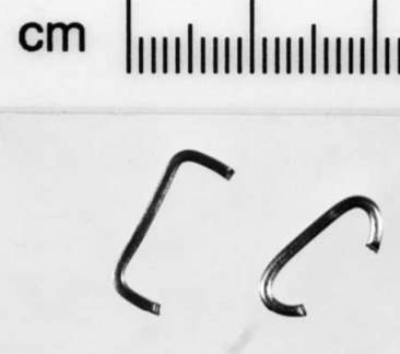
2.6.4 Biomedical Application – Fixation of a frontozygomatic fracture with a shape-memory staple
3.1.1 For wire diameter 0.005”
3.1.2 For wire diameter 0.012”
4.1.1 Tensile machine Setup & Tests
4.1.2 Result – 0.005” inches wire
4.1.3 Result – 0.012” inches wire
4.1.4 Conclusion of Tensile test
4.2 PROTOTYPE DESIGN – SMA ACTUATOR
4.2.3 Schematic circuit diagrams
4.2.5 Actuator Test 1 – Maximum angle
4.2.6 Actuator Test 2 – Actuation at 3 different angles – 50, 100, 200
APPENDIX A – Arduino program 1
APPENDIX B – Arduino program 2
LIST OF FIGURES
Figure 1 One way shape memory effect
Figure 2 Two-way shape memory effect
Figure 3 Austenite and Martensite phase transformation (strain, stress, temperature)
Figure 4 EAGLE (Electrically actuated antiglare rear view mirror)
Figure 5 (a) Placement of SMA flexure (b) Final assembly
Figure 7 (theoretical results) Stress vs Strain in 0.005″ and 0.012″
Figure 8 Dimension of hinge part and finished view
Figure 9 Tensile machine setup
Figure 10 experimental result by Honarvar et al., 2013
Figure 11 Rudder deflection in various aircraft at three airspeed
Figure 12 Dimension of rudder(left), Final rudder model (right)
Figure 13 Arduino Input commend box
Figure 14 Switch circuit to determine maximum angle
Figure 15 circuit to rotate actuator at specific angles
Figure 16 Plastic hinge (left), Metal hine (middle), Punched metal tube (right)
Figure 18 Arduino set to determine maximum angle
Figure 20 Left side rotation at 0deg, 5deg, 10deg, 20deg (left to right)
Figure 22 Temperature vs time and Temperature vs current
Figure 23 Relative effect of cooling methods (Dynalloy inc.2007)
Figure 25 Automotive Application
Figure 26 Aerospace applications
Graph 1 Stress vs Strain of 0.005” wire
Graph 2 Contraction vs Voltage of 0.005” wire
Graph 3 Force vs Voltage of 0.005” wire
Table 1 Experimental and theoretical comparison (0.005″)
Table 2 Experimental and theoretical comparison (0.012”)
Table 3 Input Output relationship
GLOSSARY
[The heading above is set to Heading 1 paragraph style but with the automatic number deleted. Paragraph styles need to be used consistently so that the automatically generated table of contents works correctly]
[ENTER YOUR GLOSSARY HERE – This section consists of a list of all specialist vocabulary or acronyms with a brief description of their meanings.]
[This document has two sections. This is the end of Section 1and Section 2 starts with Chapter 1. There is a section break at the end of the Glossary and before Chapter 1. Take care not to delete a section break as this will remove the footer and page numbering from the whole document.
To see section breaks, page breaks and other non-printing characters, click the ¶ icon on the menu bar]
1. INTRODUCTION
In year 1932, Arne Ölander was first to discover Shape memory alloy (Ölander, 1932). The significance of shape memory materials was unrecognised until William Buehler and Frederick Wang disclosed the shape memory effect (SME) in a nickel-titanium (NiTi) alloy in 1962 (Buehler, Gilfrich and Wiley, 1963). Subsequently in 1963, many commercial applications have been developed. In 1970s, NiTi application began appearing in biomedical application, not until it made a breakthrough commercials with NiTi stents in 1990s.With this breakthrough additional applications were found in electronic cable, connectors, valves, air conditioning and a variety of other production as described by Lagoudas, 2011. Also, other various application of SMAs were initiated within every field especially in engineering. Applications of SMA’s were in sectors such as aerospace, automotive, medical, structural, robotics, mini actuator, electromechanical systems, etc. (Mohd Jani et al., 2014). Eventually science and technology made reasonable advancement and understanding on behaviour of material since past decades.
Shape memory alloy (nitinol) has property by which it can recover its original shape when heated to its transformation temperature. Which is further discussed more in detail throughout the project. Due to its simple form, the complexity of SMA material is under estimated in applications. SMA actuator is presented in form of metallic wire, springs, etc. still it has multifunctional characteristics. That must be considered during system-design development. Shape memory alloy in general shows a mechanical response to non-mechanical field i.e. electrical, thermal, magnetic, etc. The responses of these material are one or more magnitude greater than response resulting from conventional material behaviour such as thermal expansion as explained by Lagoudas, 2011. One of the most common application of shape memory alloy is actuator. Until now, numerous projects on actuator designs are introduced. An overview about existing actuation designs, applications and new improved shape memory alloy actuator designs are shown by Mertmann and Vergani, 2008. Two crucial factors of actuation design are high actuation frequency and high actuation energy density and as mentioned by Lagoudas, an active material would have both high actuation frequency and high actuation energy density. It makes shape memory alloy (active material) extensively in the common engineering world.
One of the manufactures of smart materials (shape memory alloy) is dynalloy. Flexinol (shape memory alloy) is one of their products which is been used for this project. Properties of flexinol is shown in table. To begin the project, experiment is carried out with tensile machine to observe the behaviour of wire i.e. stress vs strain of wire. During the experiment, the current is passed at intervals of few mins to record the strain and stress at that current/voltage. Test setup, test conditions and data collected is shown in 4.1. Then data from experiment are compared to theoretical calculated values of strain at maximum current. This concludes that wire has same strain % as that of theory and are suitable for actuation design. Later using the data obtained, an understanding of voltage with respect to contraction is put together to design a simple shape memory actuation for rudder and flaps. Firstly, program was built to determine maximum angle that can be achieved from actuator. Further, program was modified so the rudder/flap can be moved to specific angle. This concluded with two distinct perspective towards SMA actuator in rudder- control surfaces and flaps. Also, actuation was performed for 50 cycles at a specific angle. Just to check the consistence of results throughout test and compare it with the data obtained from wire manufacture.
1.1 Aims
- To compare the theoretically & experimental behaviour of Shape memory alloy (Nitinol) wire
- To develop a prototype shape memory alloy actuator.
1.2 Objectives
- Calculate stress and strain values from experiment and compare it to the values obtain from theory.
- Build a simple controller with Arduino-Uno to control SMA wire to determine its maximum deflection. Further modify the Arduino to control SMA wire actuation at specific angles
- Demonstrates shape memory alloy (SMA) actuation in rudder/flap with Arduino programs.
1.3 Summary of project
The purpose to commence this project was to give insight of shape memory alloy actuator in engineering industry specifically aerospace as actuators are one of the most crucial application in modern engineering. Also, introducing shape memory actuator in aerospace industry would give various advantages as mention in 2.5.1. To achieve this, it was important to study the behaviour of material then implement in actuator. Summary of project is described in two sections as shown below. Also, it explains how the work will help achieve the aims.
1.3.1 Experiment outline
Two SMA wire (Flexinol) of diameter 0.005” inches and 0.012” inches were used. The wires have one-way shape memory effect as explained in 2.2.1. Wires were tested in tensile machine to determine its stress and strain. Then compared to the theoretical data calculated from SMA wire specification for further analysing the results. This result will provide a set of relations between current, voltage, load and contraction of wire which will be useful asset for actuation demonstration. Also, a brief comparison between both the wire and result attained are shown in 4.1.4.This experiment was carried out, so firstly the stress and stress values are verified and secondly a relationship between the voltage, current, force and contraction is obtained which is important to build the control system for actuator to actuate at specific angles. This relationship is not specified in SMA wire specification and is different for different diameter wire.
1.3.2 Demonstration outline
Considering the experiment results, a specific diameter was chosen for performing the tests. (As properties of SMA wire varies with respect to its diameter. It crucial to know in prior which diameter will be more suitable for actuator design). Arduino controller is programmed and a circuit is prepared for controlling actuator as shown in 4.2.2 and 4.2.3. Actuation in rudder/flap is tested at peak current of wire to achieve maximum angle. This angle was expected to be in range of (30deg-1deg) as explained in section 4.2.Then using the results from experiments, a table is prepared for voltage vs contraction which is harness to reprogramming Arduino. So, actuation is possible for these specific angles i.e. 5o ,10o and 20o. Reason behind these angles is explained in more detail in 4.2.6. By performing this, it will give strain rate, angles of actuation including maximum actuation angle possible with respect to this wire, possibility in control surface and flaps. Additionally, summary of forces wires (different diameter) can strain are mention in section5.3, this important for feasibility in actual design. Further testing in wind tunnel with a scaled model is needed to verify those forces.
2 LITERATURE REVIEW
This chapter is a review of shape memory alloy and its applications. Also, challenges face to adapt the material and its advantages as well as disadvantages are discussed.
2.1 Shape memory alloy (SMA)
Shape memory alloy are subclass of smart material, where alloys return to its original form when subjected to temperature variations. When SMA reaches to its transformation temperature, it deforms to its original structure. Below its transformation temperature (i.e. in cooled form), it can be easily deformed to any shape and it will retain as it has low yield strength. While returning to its original shape upon heating, if it come across any resistance. It will produce extremely large forces (Song, 2007). This transformation effect is called as shape memory effect. There are several alloys demonstrating shape memory effect. In comparison with other alloys, Nickel titanium alloy (Nitinol) is commonly used for its performance and reliability (Salehi et al., 2013).
2.2 Shape memory effect
Shape memory alloy has two shape memory effect and pseudoplasticity effect. Shape memory effects has two effects one way effect and two-way effect.
2.2.1 One-way effect:
This is one of most adapted method due to its low production cost and lower amount of processing. NiTi senses a change in ambient temperature and able to convert its shape to a preprogramed structure. While NiTi is soft and easily deformable in its lower temperature form (martensite), it resumes its original shape and rigidity when heated to its transformation temperature form (austenite) (Fig.3). This is called the one-way shape memory effect (MIHÁLCZ, 2001). Example: As shown in Figure 1, (a) is the original shape of the wire when it is produced (high temperature). Then it has been deformed in any shape (b) (cooling state). Then in step (c) wire is heated to its transformation temperature. So, it returns to its original shape (a). Once the wire is cooled, it will remain in same shape until deformed again (d).
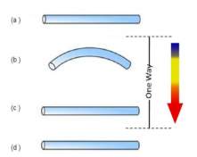
Figure 1 One way shape memory effect
2.2.2 Two-way effect:
Two-way effect has ability to memorise two shapes i.e. one at high temperature and other at low temperature. When the shape memory alloy is heated, it transforms to the deformed pre-set shape at high temperature and upon cooling it deforms into alternative shape. This effect is called as two-way shape memory effect (MIHÁLCZ, 2001). Perkins and Hodgson describe this effect in more detail and give processing methods on how to obtain alloys that will exhibit the two-way effect. Ryhänen describes two methods for obtaining two-way memory.
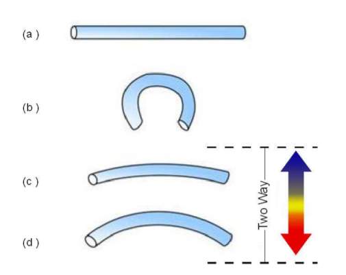
Figure 2 Two-way shape memory effect
2.2.3 Pseudoelastic:
Pseudoelastic is also called super-elasticity. Pseudoelastic is a unique property, it doesn’t require any thermal activation to revert to its original shape. SMA returns to its original shape after mechanical load is applied to material at temperature between austenite and martensite. Austenite and martensite temperature transformation is describe more in detail in section 2.3. As described by Lagoudas in section 1.5, the pseudoelastic behaviour of SMA is linked with transformation where stress is induced, which leads to strain generation while mechanical load and successive strain recovery upon unloading at temperature above Austenite. While the study of pseudoplasticity, Lagoudas mentioned that the term describes both rubber like effect and super-elastic behaviour where the rubber effect is referred to reversible reorientation of martensite which is limited to martensite phase only and thermomechanical load causes the reversible phase transformation is super-elastic behaviour. Pseudoplasticity (superelastic behaviour) phase transformation is shown in Figure 3.
2.3 Molecular transformation
The molecular transformation for phases (Austenite to Martensite) in one-way shape memory effect, two-way shape memory effect and pseudoelastic is shown in Figure 3. Terms as and Ms denotes Austenite and Martensite start temperature (phase) whereas Af and Mf denotes Austenite and Martensite finish temperature (phase).
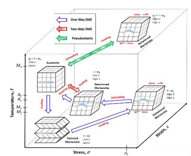
Figure 3 Austenite and Martensite phase transformation (strain, stress, temperature)
The figure illustrates that, one-way shape memory effect: austenite phase – original shape is remembered by wire at high temperature. Twinned martensite phase (molecules are transformed)- wire cooled down after it remembers the original shape. Then the forces are applied to form detwinned martensite. Once, the shape is adapted the forces are removed and the detwinned martensite is the form which is deformed shaped of wire. So, to return to its original shape (austenite phase) wire needs to be heated at its transformation temperature and would remain in same shape (twinned martensite) until it is deformed again (detwinned martensite). Now for two- way effect, when the wire is cooled it will go back to detwinned shape instead of remaining in same shape (twinned martensite). That’s how it remembered two shape (one at high temperature and other one at low temperature).
2.4 Challenges face to adapt material in engineering
Comparing the conventional actuation systems with shape memory actuation, the difference is the unique characteristics and behaviour of SMA. Challenges which are face to adapt the material in engineering are described below. Also, several methods the difficulties can be overcome and which of those methods are implemented in this project are mentioned.
2.4.1 Low Controllability and accuracy
Shape memory material recovery to its original form on heating. Upon cooling, it stretches out again. This point obviously highlights, two crucial facts. That wire has two states i.e. heating and cooling state. Shape memory alloy, have trouble to control the heating time and cooling time as investigated by Mohd Jani et al., 2014. It is important to consider that wire will take different time to heat up and cooling down. Also, the process of heating and cooling of wire will depend on the method adapted to transfer heat to the wire and cool off the wire. While designing SMA actuator, it took quite a while to overcome this issue during the project. In some case, the wire was damage due to insufficient time provided to wire for cooling. Since the wire was not completely cooled and heated again. It caused overheating over number of cycles and damaged the wire by permeant deformation. This reduces the accuracy of wire, i.e. the strain percentage and the performance is decreased. As shown in 4.2.5, the test was performed to determine maximum angle. While it was tested for 10 cycles, the wire got damaged and no strain was seen in wire. At first, maximum current was passed which was not a major issue but the cooling time required by wire for that heating was estimated relatively less. So, couple of more experiment were carried out to check the appropriate time to gain maximum performance and accuracy.
2.4.2 Narrow bandwidth
SMA material have narrow bandwidth, i.e. they have comparatively high heat capacity and density. Thus, they have trouble to promptly transfer heat to the wire and more importantly remove the heat out of the material i.e. cool the material. As studied by Featherstone & Teh 2006, and Qiu et al., 2001, that rapid heating is possibly achieved easily with various methods. One of the method was passing large current to increase heating transfer rate. However, controllability still plays a vital role which should be overcome to monitor the heat transfer time and cooling time while controlling not to burn or damage the system. Also, the mechanism of heat conduction limits the heat energy removal rate. While design the actuator, factor which affects is the size of SMA. Smaller diameter wire has higher resistivity so it heats and cools faster due to its higher surface to volume ratio as studied by An et al., 2008. Thus, wire diameter is directly proportional to bandwidth of wire. Any change in wire diameter will affect the bandwidth. Therefore, wire was reasonably chosen for the actuation demonstration. Further strategies on cooling and experiment which was performed with thermal protection coating and without thermal coating protection is discussed in section 5.1.
2.4.3 Durability and reliability
Durability and reliability is critical factor for long term stability, safety and functionality of systems. Research by Erbstoeszer et al., 2000 reveals when SMA actuators are exposed to multiple transformation cycles it shows softening behaviour i.e. the strain % is decreased as the actuator cycles. This behaviour was also noticed in this project, when 50cycles were carried out at little less then peak current. Studies done by Tang and Sandström, 1993 shows that constant loading of higher load, which is not advise by manufacturer in SMA actuators has led to decrease in strain as cycles are increased in actuator. This concludes that SMA actuator should be avoided from overstressing and overstraining for long duration with non-commended load. Hence, this is not the issue faced for this project as the load is within the limit of manufacturer though the overheating was an issue which was causing the transformation cycles to reduction the stroke i.e. the strain rate. This issue was solved by adjusting cooling time.
2.4.4 Number of cycle
Flexinol from dynalloy inc assures that the wire can obtain repeatable motion for tens of millions of cycles in proper condition. It also says, if the higher stresses are executed then reduction in strain in observed still decent motion maybe gained for only hundreds or a few thousands of cycles. If the stresses are too high and temperature cause overheating, it will cause permanent deformation will can lead to no cycles. Due to less degradation and fatigue of SMA material, results over millions of cycles are readily possible with suitable guidance and procedure.
2.5 Advantages and disadvantages of SMA
2.5.1 Advantages
From overall literature review and application of shape memory alloy, these are some advantages and disadvantages concluded.
- Noiseless actuation
- Anti-corrosion
- Small size – good adaption for mini mechanism a
- Highest power to weight ration among light weight technologies
- Sensing the actuation through resistance measurement
- Low voltage, activation of actuation can be accomplished by passing small voltage due to its high electrical resistivity
2.5.2 Disadvantages
- Low energy efficiency
- Low response speed
- Non-linear behaviour
Few more advantages described by Mohd Jani et al., 2014 in section 3.1, he states that “shape memory alloy endorse the development of more advanced and cheaper actuators with a significant reduction in mechanical complexity and size”. Also, comparison between actuator performance (table in section 3.1) displays one of the highest work density, with comparison of electric motors, SMA gives 25 times more and can lift more than 100 times of its weight. It also says NiTi SMA is bio-compatible and it makes “an obvious choice for designers for actuators that provide significant displacement and forces, with no critical requirements for a short response time or high efficiency”.
2.6 Shape memory alloy applications
There are numerous study and development leading the shaping memory alloy applications in all field of engineering. In this section 4 examples of SMA application each in different engineering field (i.e. Aerospace, Automotive, Robotic and biomedical is briefly discussed.
2.6.1 Automotive Applications – EAGLE (Electrically Actuated antiglare rear-view mirror)
For the comfort and safety of driver, an automatic antiglare rear- view mirror system is a developed using shape memory alloy. System requires low forces with silent bi-stable movement which are applicable for SMA actuator.
Figure 4 EAGLE (Electrically actuated antiglare rear view mirror)
The design was started as conceptual design which is demonstrated to provide certain understanding. Later preliminary overview of the working principle was provided together with conceptual design, where a series of deliberations regarding kinematics and layout of electronic sensors were discussed. This gave an understanding of a fully controlled mechatronic prototype. This prototype of EAGLE system was tested and an experimental confirmation was given that it can satisfy functional test requirements and fatigue. Detail about the mechanism and control system of EAGLE can be read more in Luchetti et al., 2009 PP.717-724.
Further shape memory alloy automotive applications can be read in section 5.1 and a list of applications are found in table 11 in Mohd Jani et al., 2014 PP.1078-1113 and a picture indicating different application is shown in appendix C.
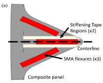
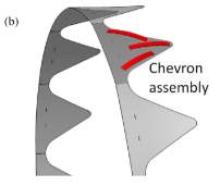
2.6.2 Aerospace Application – Boeing’s variable geometry chevron
SMA actuators was developed, which is also known as a variable geometry chevron (VGC) and been installed on a GE90-115B jet engine (for the Boeing 777-300 ER commercial aircraft). This utilize lightweight, robust, and compact shape memory alloy (SMA) actuators. To optimize acoustic (noise reduction) and performance purposes at manifold flight conditions, these actuators morph the shape of chevrons on the trailing edge of a jet engine.
A successfully flight testing was also held with SMA actuator. This device has been proved to be very effective in noised reduction during take-off by maximising the chevron deflection and increase efficiency during cruise by minimising chevron deflection. Also, shock cell generated cabin noise reduction during cruise. Most importantly, the VGC concept demonstrated an exciting capability to optimize jet nozzle performance at multiple flight conditions. (Calkins, H. Mabe and W. Butler, 2006)
![Boeing’s variable geometry chevron (VGC) [238].](https://images.ukdissertations.com/11/0008607.007.jpg)
Figure 5 (a) Placement of SMA flexure (b) Final assembly
Additionally, shape memory alloy aerospace applications can be read in section 5.2 and a list of applications are found in table 14 in Mohd Jani et al., 2014 PP.1078-1113 and a picture indicating different applications is shown in appendix C.
2.6.3 Robotic Application – Prosthetic hand
Chee, Yokoi and Arai designed a SMA actuator design for a prosthetic hand. In this case, two actuators were inserted from both ends of the out stainless tube. Stainless tube function as heat sink and when wire is activated they guide simultaneously. No conventional push pull or spring actuators are used (CHEE, S., YOKOI, H. AND ARAI, T, 2005).
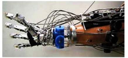
Control system sends signal to pass current at different times to wires via electrode points (which are placed at the centre of tube and each end of tube). This will create motion will almost replicate action of human finger actions. To avoid overheating issue and excess power usage in actuators, PWM controller is used to pulse the high voltage periodically in millisecond (Mohd Jani et al., 2014).
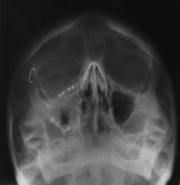
2.6.4 Biomedical Application – Fixation of a frontozygomatic fracture with a shape-memory staple
(Laster et al., 2001 PP.324-325.)
3 THEORETICAL STUDY
3.1 Theoretical calculation:
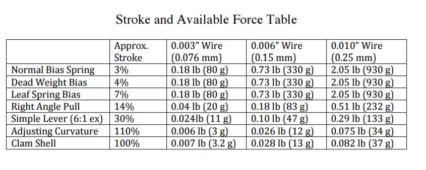
Calculating strain and stress values base on the percentage contraction and maximum force a wire can pull will give a minor theoretical review of SMA properties. The datasheet of wire used for this project is of flexinol. It describes that the normal bias springs that increase their force as the Flexinol® actuators contract have only 3-4% stroke.
3.1.1 For wire diameter 0.005”
For 0.005” wire the pull force exerted is 223grams i.e. 2. 19N.The length of wire used in this project was 8.5cm approximately and the contract is 3%-4% to its length for maximum pull force. The stress and strain is calculated for maximum pull force of wire and maximum strain for maximum load. When current of 340mA is passed.
Fmax = 2.19N
For a wire, the cross-sectional area becomes:
A= π r2 =3.14 x 6.35 x 10-52=1.27 x 10⁻⁸
L = 85mm
STRAIN
So, the strain for 3% is
∆L
= 3% of 85mm = 0.03 x 85mm = 2.55mm
∆L
= 4% of 85mm = 0.04 x 85mm = 3.4mm
So, the strain value of wire would be around 2.55-3.5mm
STRESS
Formula for stress =
FA = 2.191.27 x 10-8 = 1.72 x 10⁸
3.1.2 For wire diameter 0.012”
For 0.012” wire the pull force exerted is 1280grams i.e. 12.55N. The length of wire used in this project was 8.5cm approximately and the contract is assumed to be 6%-7%to its length for maximum pull force. When current of 1.5A is passed.
For a wire, the cross-sectional area becomes:
A= π r2 =3.14 x 1.524 x 10-42=7.3 x 10⁻⁸
L = 85mm
STRAIN
So, the strain 6%-7% is calculated below and as per theory strain % is depend on the force exerted to shape memory wire.
∆L
= 6% of 85mm = 0.06x 85mm = 5.1mm
∆L
= 7% of 85mm = 0.07x 85mm = 5.95mm
STRESS
Formula for stress =
FA = 12.557.3 x 10-8 = 1.72 x 10⁸
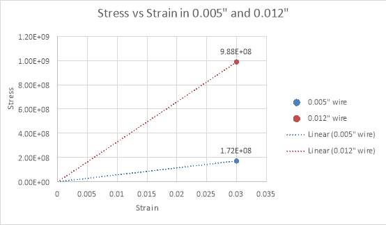
Figure 7 (theoretical results) Stress vs Strain in 0.005″ and 0.012″
The Graph, shows maximum stress and strain values for both wires for maximum current.
3.2 Theoretical study
The theoretical study is based on wire manufactured specification i.e. dynalloy inc and literature review. As the have experimental proven the performance of wire and limitations. This will help to understand the wire limitations and verify those limitations and behaviours with experiment performed in section 4.2.6. So, an appropriate conclusion can be achieved.
Movements
The movement of flexinol or the contraction is measured in term of percentage of the length contracted by wire.
The movement or stroke of Flexinol actuator wire is measured as a percentage of the length of the wire being used and is determined, in part, by the level of stress one uses to reset the wire, or to stretch it in its low temperature phase. This opposing force, used to stretch the wire, is called the bias force. In most applications, the bias force is exerted on the wire constantly, and on each cycle as the wire cools, this force elongates it. If no force is exerted as the wire cools, very little deformation or stretch occurs in the cool, room temperature state and correspondingly very little contraction occurs upon heating. Up to a point the higher the load the higher the stroke. The strength of the wire, its pulling force and the bias force needed to stretch the wire back out are a function of the wire size or cross sectional area and can be measured in pounds per square inch If a load of 34.5 MPa is maintained during cooling, then about 3% memory strain will be obtained. At 69 MPa, about 4% results, and with 103 MPa and above, nearly 5% is obtained. However, there is a limit to how much stress can be applied. Far more important to stroke is how the wire is physically attached and made to operate. Dynamics in applied stress and leverage also vary how much the actuator wires move. While normal bias springs that increase their force as the Flexinol actuators contract have only 3-4% stroke, reverse bias forces which decrease as the actuator wires contract can readily allow the wire to flex up to 7%. Mechanics of the device in which it is used can convert this small stroke into movements over 100% of the wires’ length and at the same time provide a reverse bias force. The stress or force exerted by Flexinol actuator wires is sufficient to be leveraged into significant movement and still be quite strong. Some basic structures, their percent of movement, and the approximate available force
Electrical
When electrical path is chosen to operate the wire, it should be known that temperature is directly related to the current density passing through the wire. A guidance to
4 EXPERIEMENTAL STUDY
4.1 TENSILE TEST – SMA WIRES
Tensile machine was used to performed the wire testing. This machine is appropriate for studying mechanical behaviour of various material like iron, metal, rubber, plastic, ceramic, fabric, composite, cables and wires (Mechatronicindia.com, 2009). In tensile machine, both end of wire is clipped with the pully so the wire is straight as shown in figure. It is important that the wire is tied straight so the strain is accurately measured. Once the wire is straight, the reading is taken at several current/voltage. Strain and stress values obtain from the experiment are used to plot graphs and study the behaviour of wire. Later, using the reading a table is prepared where it shows the voltage/current vs contraction, which is useful for the actuation design.
4.1.1 Tensile machine Setup & Tests
List of apparatuses used for testing: Tensile machine, Power supply, 2 flexional wire (0.005” & 0.012”), rig part, connecting clips and jumper wires.3
For this testing, Rig part was manufacture in machine shop with rigid plastic. As shown in figure 8, it was design in catia as per tensile machine requirement/ fitting. So, when the current is pass through the wire, there is no connection to the tensile machine nor there is any cross connection and shock circuit.
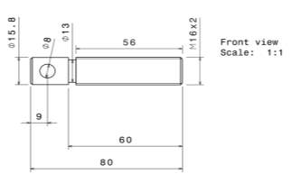
Figure 8 Dimension of hinge part and finished view
Setup for both wire test was same. SMA wire was first connected to tensile machine via pulley as shown in figure. Then the clips of jumper wire were connected to power supply (ground and power) and end of jumper wires were connected to ends of SMA wire. The wire was aligned straight prior the start of test as shown in figure 9.
Test conditions:
- Current/voltage is passed through the wire at intervals of 2mins. (so, enough time is given to wire to cool down)
- Zero load is setup for initialising test
- Wire must be straight before starting the test
Figure 9 Tensile machine setup
4.1.2 Result – 0.005” inches wire
After performing the test for wire 0.005” diameter, results obtained are shown below,
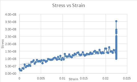
Graph 1 Stress vs Strain of 0.005” wire
Graph 1, shows maximum strain the wire can take is 0.0225 and maximum stress is
1.6 x 10⁸. The waves in the graph are due the temperature variation, which take place due the environment. So, when the current is passed the wire is heated and its assumed in-between temperature falls due to air/surrounding temperature behind comparative cold then the wire temperature which might lead to heat transfer. This temperature fall are the reason that creates that wavy output instead of linear. There would be more reason to it, as the voltage and current are fluctuating due to manually handling the rotor of current in power supply. It could be that for an instant the current is not sufficient or lower than that of pervious current. Also, one of reason could be the connection been moved while performing the experiment even though care was taken.
Similar results for stress and strain are obtained by tensile experiment performed by Honarvar et al., 2013 for 0.005” as shown in figure below for 0.15mm
≈0.005″, though the graph appear bit different due to method of documenting the reading from test.
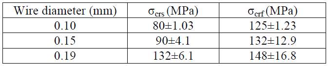
Figure 10 experimental result by Honarvar et al., 2013
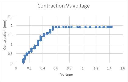
Graph 2 Contraction vs Voltage of 0.005” wire
In graph 2, Linear relationship is observed between the voltage and contraction until the point the when the wire is overheating and there is no more contraction seen. As the current/voltage is continuous, the wire exceeds the transformation temperature by 0.55V by which constant value of contraction is seen. Main point noted here is the linear relationship and wire getting permanent damage as it exceeds beyond its transformation temperature.
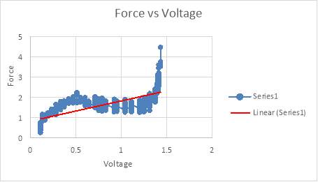
Graph 3 Force vs Voltage of 0.005” wire
Graph 3, The result of this graph can be explained in conjunction with Graph 1 and Graph 2 .As in graph 2, the contraction is constant after 0.55V so the force exerted after 0.55V is stress of wire when wire is no longer contracting. So, it is the strength put forth by wire to contract or react to the extra heat produced within the wire. Force which wire can hold is 4.47N at maximum current (overheating stage). And the pull force of wire through contraction would be the force value on 0.55V i.e.
≈2.13N.
4.1.3 Result – 0.012” inches wire
After performing the test for wire 0.012” diameter, results obtained are shown below,
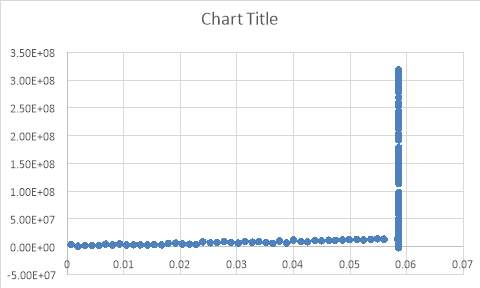
Graph 4 Stress vs Strain in 0.012″ wire (circled part from figure 12)
Graph 4 and 5, shows maximum strain the wire can take approximately 0.058 and maximum stress is
1.74x 10⁸. The waves in the graph are due the same reason as described in graph 1 i.e. temperature variation, which take place due to the environment. So, when current is passed through the wire, it gets heated and start to contract though the current is fluctuating due to rotation
So, when the current is passed the wire is heated and its assumed in-between temperature falls due to air/surrounding temperature behind comparative cold then the wire temperature which might lead to heat transfer. This temperature fall are the reason that creates that wavy output instead of linear. There would be more reason to it, as the voltage and current are fluctuating due to manually handling the rotor of current in power supply. It could be that for an instant the current is not sufficient or lower than that of pervious current. Also, one of reason could be the connection been moved while performing the experiment even though care was taken.
4.1.4 Conclusion of Tensile test
Table 1 Experimental and theoretical comparison (0.005″)
| Theoretical | Experimental | |
| Pull Force (N) | 2.19 | 2.13 |
| Contraction (mm) | 2.55 | 1.91 |
| Stress (N/mm) | 1.72 x 10⁸ | 1.6 x 10⁸ |
| Strain (mm) | 0.03 | 0.0225 |
Table 2 Experimental and theoretical comparison (0.012”)
| Theoretical | Experimental | |
| Pull Force (N) | 12.55 | 30N |
| Contraction (mm) | 5.1 | 4.91 |
| Stress (N/mm) | 1.72 x 10⁸ | 1.74 x 10⁸ |
| Strain (mm) | 0.06 | 0.058 |
Comparing the experiment and theoretical results of 0.005” and 0.012” wire, it is observed that results are obtained are quite similar to each other. This verifies the wire properties and also give the strain % which is a key point for SMA actuator. Also, this experiment is used to observe how much wire can contract without applying external force to stretch the wire. As applying external force to stretch the wire, will increased contraction %.
This experiment concludes the wire contract 3% at maximum current (320mA) for 0.005” wire and 6% at maximum current of 1.5A for 0.012” without applying force to stretch wire. The force recorded is the pull force i.e. the force wire can pull when contracting due to applied current. It is important to know, the contract % can increase with increase in external force applied to stretch wire during the cooling process. During experiment, it was make sure that there is no external force, so the contraction value obtained is truly on based on nature of wire. As it will be useful in demonstration, as there is no opposing or external force applied while using SMA actuator. We can know how much exactly the wire is contracted and how much it can pull.
Limitation to test and future suggestions for tests
It can damage wire and a lot of attention has to be paid while testing the wire. Almost 8 test or more test were performed to achieve the above results. Failure of tests were overheating causing no contractions, setup for same diameter wire and electrical connections. No cycles were performed during this test though there is limitation to number of cycle wire can perform which is discussed in 2.4.4.
For future test, it would be a good to determine how much wire can strain for different external force. Also, using control system for temperature to determine the temperature variation during the test will be using to understand the molecular transformation material undergoes while heated and cooled.
4.2 PROTOTYPE DESIGN – SMA ACTUATOR
During the period of this research several designs for shape memory actuator were reviewed as few discussed in point_2.6. Main motive behind the design of actuation was to replace the control surfaces like rudder, elevator with lighter and simple mechanism of SMA actuator. Also, flaps were considered later as part of this demonstration. Though it is tough to control nitinol wire and maintain performance. Finally, a simple implication of linear actuator was chosen to build the actuator. The foremost purpose of this design is to explore the shape memory material and feasibility for control application. Number of stroke and limitation were also taken in consideration. Also, the design has tried to cover range of angles (including minimum and maximum). Though, there has been limit to certain boundary which are later discussed. As shown in Figure 7, there are particularly 3 different rudder deflection for each aircraft at 3 different airspeed. Using this small range, deflection that rudder must perform was set to be in range of (30deg-1deg). Now, From Actuator test 1, the maximum deflection would be set and further using results from 0.012” wire we can decide the other values which we want the rudder to move.
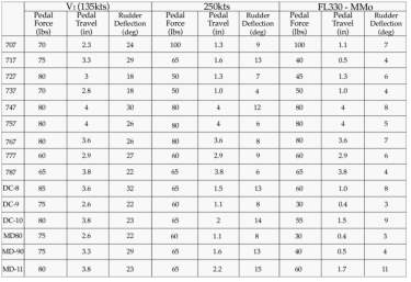
Figure 11 Rudder deflection in various aircraft at three airspeed
(Aircraft Design and operation briefing leaflet, 2011)
Bearing that only two diameter wire were available at the time of project i.e. 0.005” and 0.012”. The maximum deflection angle is going to be limited by the diameter and length of the wire use for the demonstration.
4.2.1 Rudder
Before manufacturing rudder, it wasn’t thought how size of rudder would affect the wire. So, rudder dimension was based on the length of wire intended to use, and wire that will be attached to rudder decided to be 8.5cm. Firstly, vertical stabilizer – rudder was design in catia then manufactured in workshop with the help of staff. Balsa wood was used to build rudder. Box was attached to vertical stabilizer for the support. Figure shows the dimension of rudder and initial stage of rudder. Later the rudder was altered by fixing a plastic hinge and rear of vertical stabilizer with screw- nut to hold wire. It was then discovered that plastic hinge was not the correct choice as they started melting during the tests. So, they were replaced with metal hinge.
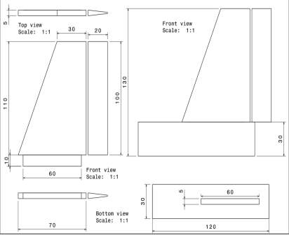
Figure 12 Dimension of rudder(left), Final rudder model (right)
4.2.2 Arduino Programs
Arduino program gives an interface between input and output for an application. For this project, two programs are written and run on Arduino Uno.
Program 1: Simple switch program to pass maximum current to the wire on each side of rudder at a time to obtain maximum angle of attack. This program works in simplified manner. Input here is a switch button. As the switch button is on, the maximum current is passed on one side of wire while other wire is in relaxed stage. After few mins of delay vice versa. The Arduino program is can be found in APPENDIX A – Arduino program 1. Once the rudder is moved to maximum angle, the angle is noted down.
Program 2: The input for this program is also controller by a switch button and output is in degree of rotation in rudder. As the button is pressed, program will return a statement in serial monitor of Arduino program asking for input (i.e. enter value in degree to rotate the rudder) as shown in figure 8. After every input, button must be pressed again if you want to further use the program. Input values which can be identified by program are (R5, R10, R20, L5, L10, L20) here R stand for right of rudder, L stand for left of rudder and numeric values 5,10,20 stand for values in degree to rotate. Any other values other than this will be ignore and program will return nothing. For example, after R10, button should be pressed again so you can enter the value and rotate the rudder. When the degree of rotation is input, the signal is send in form of voltage/current to the Arduino which turns the switch on of phase which will rotate the rudder to that specific degree. Rotation is from the centre axis of rudder. Also, a delay is after every rotation so the wire has time to cool down. Further explanation on behaviour of wire and input output relationship in program is discussed in section 4.2.6.
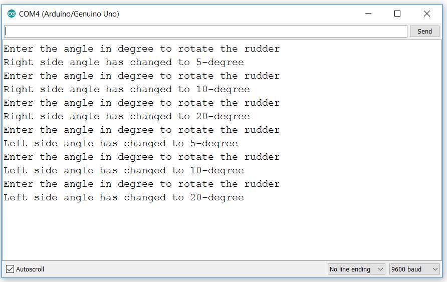
Figure 13 Arduino Input commend box
4.2.3 Schematic circuit diagrams
There are two schematic diagrams related to Arduino program respectively.
Circuit 1
Two resistors of 7
Ωare used for this circuit and both resistor is calculated on base on maximum current to be pass through the wire i.e. 1.3A. A constant voltage of 5V and 2A is set for the test. Arduino pin 13 and pin 12 is used to give signal to the transistors to switch. Arduino pins can only give 20mA current and 5V pin can give only 500mA and at max 900mA when connected to external battery to Arduino board. So, to get 1.3A external power supply was directly connected to the end of wires. A switch button is used to control the circuit loop.
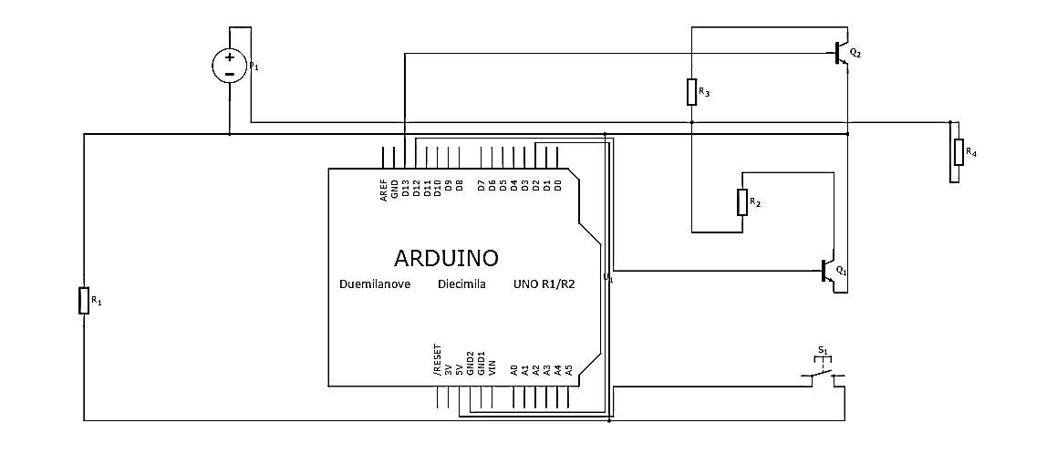
Figure 14 Switch circuit to determine maximum angle
Circuit 2:
Four resistor ad six transistors are used in this circuit. Two resistor of value 2
Ωand other two of 5
Ω. 5
Ωresistor is connected Q1 and Q4 transistor for 5 degree rotate as output. Similarly, 2
Ωis connected to Q2 and Q5. All the wiring is shown in Figure 11. This circuit works on the input given to the serial monitor, as there is an input, the signal from Arduino board is sent. The signal that pass the current to the respective switch to turn ON. This let the current flow through the resistor to the wire. Different current is pass for different angle of attack.
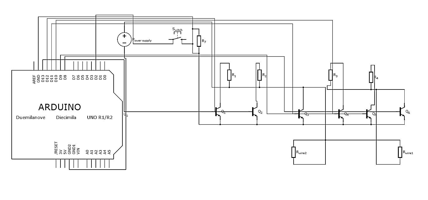
Figure 15 circuit to rotate actuator at specific angles
4.2.4 Actuator set ups
Initially the actuator has plastic hinge and the other end of fixation was tough to decide. After numerous tries, a simple combination of screw and bolt is used. As it is not the best method to hold the wire but it was 80-90% effective. As seen in figure 11, wire was passed through the metal tube and punched. This will hold the wire, when pass through the hinge. Finally, wires were put on the both the side of rudder as shown in figure 12. Wire were made sure lies in straight alignment and nut is as tight as possible.
Figure 16 Plastic hinge (left), Metal hine (middle), Punched metal tube (right)
Test was performed on insulated sheet of material. Eight crocodile clips were used connections to wire and from power supply and jumper wires. At first, displacement sensor was planned to use but due to small size of rudder, the values obtained from sensor was not accurate and secondly sensor was not appropriate for such testing. Position sensor was a good option but due to small rudder size, placement of sensor was an issue. Later, to simplify the issue – a protractor was just to measure the angle. It was made sure before every test that protractor is placed at right angle so the readings are as accurate as possible.
Further, the power supply was set to 5V constant so there can be fluctuation in current as need by rudder during the test or vice versa with 2A current. Wire use for testing was 0.012” diameter wire. This wire was chosen due to its diameter, it is easy to fix on rudder & won’t get damaged as easy as of 0.005”. Also, controlling 0.012” wire is better 0.005” as it has more pull force and contraction is visible. As changes of getting damaged are less compared to small diameter wire, many tests can be performed to test the consistence of result.
4.2.5 Actuator Test 1 – Maximum angle
Test was performed to determine the maximum angle can be rudder rotate using SMA wire actuator. Before the actual test, a minor test was performed with LED to check the program. Once the program was working, wire was put under testing. It was determined that the maximum angle is 20degree after more than 15 test.
Figure 18 Arduino set to determine maximum angle
4.2.6 Actuator Test 2 – Actuation at 3 different angles – 50, 100, 200
RUDDER
For control surfaces, it is important that rudder can be control/rotate in both sides without any interface or affecting the other side. So, efforts are made to demonstrate similar control with the help of SMA wire. With the help of Arduino, it was make sure the transistor switches correct to the give input. Also, it was made possible that rudder rotate at three different angles i.e. 50, 100, 200. Arduino Setup is shown in figure 15
Full setup picture
Test 1– (Rotating rudder to right and left individually)
To start with test, both right and left side of rudder were tested individually at all three angles. There was a delay of 2 seconds given so the wire can cool down as per datasheet provide by dynalloy for flexinol wire(SMA). Results achieved form the test were quite accurate. When the test was repeated over period it was noticed the results were not consistent, there was several different behaviours noted such as no contraction at all, minor contraction leading the angle of rotate to reduce by 60%, wire contracted for long duration, etc. This behaviour of result of overheating which was cause by repeating the test in short period, atmospheric temperature which was changing due to environment, test setup and many more. To reduce such behaviour few majors were taken. Firstly, the duration was made 4second which was found to be enough for wire to relax. Wire was also tested with 5 and 6second delay which also good for wire and best results were achieve for multiple testing. Also, couple of changes were made to test setup such as replacing plastic jumper wire with crocodile clip jumper wires, plastic hinge with metallic hinge (but it caused current lost as no proper insulation was applied), the transistor was spaced properly for better performance. Sensible outcome was seen around 20-25tests had same results. After that, there were some problems seen in 50 rotation angle.
Table 3 Input Output relationship
| Input in terms of current and voltage | Output in degree of rotation | |
| 500mA (5V) | 1.25V (2A) | 50 |
| 1A (5V) | 1.76V (2A) | 100 |
| 1.3A/1.35A (5V) | 2.44V (2A) | 200 |
Result from the above test in shown in figure 16, It clearly shows the rudder being at three different angles starting from 0degree. Also, to hold the rudder that degree, a locking mechanism is needed cause as wire get relaxed it will try to move and degree will change. A locking mechanism will help achieve the accuracy by hold the wire and not letting it deflect even when it is cooled.
Figure 20 Left side rotation at 0deg, 5deg, 10deg, 20deg (left to right)
Test 2– (Rotating rudder from left to right)
This provided some vital information which conclude the design needs a lot improvements. For this test, main target was to rotate the rudder from left to right completely. To achieve this both wire must be connected straight to rudder as shown in figure and move simultaneously from one side to other.
One major problem encounter was when rudder is commended to move left, it get restrained by the other side of the wire. As rudder moves left, the right wire pull it towards right as it can be stretched. This problem lead to lack of rotation. Even if the rudder to left side by 10deg, within no time it pulls to zero. Maximum angle achieved by passing maximum current for this setup was 10degree but this is not quite consistent. So, this setup is no suitable in control surface. This make it difficult to work and useless for rudder. SMA wire is strong, can pull a lot force and help deflect the rudder. Further wind tunnel testing would have ensured the program is suitable just if mechanism is modified for better relation between both side of wire. Other setup was thought to make the rudder movement possible but that was not implemented due not enough time, not sure about feasibility and lack of things need to make prototype.
FLAP
Whereas test 1 program and setup would work efficiently for flap, it will give good results for flaps. As flap only need one motion instead of two. Also, this mechanism will make flap light and better with accuracy. Further testing in wind tunnel can be proceed to ensure SMA wire actuator for flap is appropriate design. In case of flaps, wire with less force and small diameter wire can be used.
5 Discussion
In this chapter, discussion is made on shape memory alloy cooling process, its performance, forces and future modification to prototype design.
5.1 Cooling processes
Polydopamine coating for thermal insulation of shape memory alloy wires. Experiment by Sahlabadi et al., 2016 showed that the coating reduced the surface temperature by as much as 45%. Reduction in temperature in such large % can be advantage to wire. So, wire will take less time to heat as well as less to cool. This will increase the performance and accuracy of wire. Also, the controllability and reliability of wire will be enhanced. Figure, shows the significant difference in result obtain from uncoated and coated wire. Also in figure, it is observed that the current requirement changes slight by few mA, so the wire will need more voltage/current to get heated but it will help reduce the cooling time.
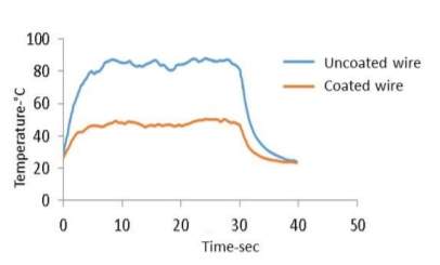
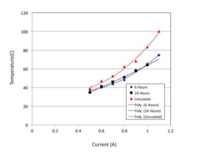
Figure 22 Temperature vs time and Temperature vs current
Several other strategies were developed to accelerate the cooling process. Some of the active cooling processes are Forced air, conductive materials, Flowing liquid, Thermoelectric modules, Heat sinks, etc. as shown in figure 23, ratio of improvement in speed of actuation with different cooling methods. Hence, active cooling is not reasonable in many ways since, it contributes to increase weight, complexity of mechanical and control of system, and cost (DYNALLOY INC.2007)
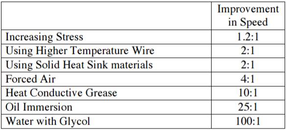
Figure 23 Relative effect of cooling methods (Dynalloy inc.2007)
5.2 Performance
Few points which are concluded from above tests regarding the performance of shape memory alloy actuator are as follows:
- Precise position can be accomplished by shape memory alloy only if the temperature control system is developed. Preferably, electrical control system would be closer to control temperature and feedback loop.
- Usually if the wire is damaged, it will be in form of reduced stroke, no stroke or wire would be permanently elongated results low performance than pervious stroke. So, it is important to determine the max performance of wire with a set of wires with a 10-100 cycles. This will help to know the limit of wire which can then be avoided while performing the test. This will help balance the performance.
- To reduce the risk of low performance, it is always a good to use non-conductive material for connecting SMA as to avoid electrical path along the wire. Also, to use temperature resistance material so it doesn’t melt or get effected by the wire temperature. As wires temperature are high enough to melt plastics.
- SMA wire are very strong and difficult to cut. So, cutting the wire with cutter used for copper wire are not good enough. There would be need for stainless steel cutters if wire length is need to be altered. As using wires of longer length than needed, will reduce the performance as the other piece of will be affected by the current pass to this end of wire.
5.3 Forces
As data obtained from wire datasheet, number of wire required to exerted largest pull force is calculated and power consumption for that number of wire
Table 4 Wire specification
| Diameter of wire (inch) | Resistance
(ohms/inch) |
Current
(mA) |
Pull Forces
(grams) |
Number of wires | Power
(watts) |
| 0.002 | 12.7 | 85 | 14 | 254.3 | 23 |
| 0.005 | 1.9 | 320 | 89 | 40 | 7.8 |
| 0.008 | 0.74 | 660 | 228 | 16 | 5.2 |
| 0.012 | 0.31 | 1500 | 1280 | 2.85
~ 3 |
2.09 |
| 0.02 | 0.11 | 4000 | 3560 | 1 | 1.76 |
5.4 Modification to design
As full control over both side of rudder wasn’t completely achieved. Further to achieve the full rudder movement, this conceptual design is shown. Not sure if issue can be possibly solved but surely it can help to reduce the problem.
In figure, a wire is attached to rubber through a wax nob. Also, wire can be connected through a connect to the rubber. Rubber can be strong flexible wire/string. Just for demonstration a simple rubber band is used. In figure 19, the rudder is at zero angle and you can see the wire and the rubber string is relaxed. While in Figure 20, you can see the rudder has moved to left side at some angle 20 and hold on that angle but still the right-side wire is relaxed and only the rubber is stretched. Once the locking mechanism is relished, the rubber will pull back the rudder at 0degree and then right wire can move to achieve full deflection. Things can be used instead of rubber are spring, elastic wires, flexible materials, etc. As the idea of spring was discussed with supervisor, it was concluded that the design won’t work cause
Figure 24 left – wire attached to rubber through a nob, right top – Rudder is at zero degree and rubber is not stretched out, right bottom – Rudder is at 20 degree and rubber is stretched out
6 Conclusion
Shape memory alloy actuator has several aspects which must be considered before finalising the prototype design. In this project, studying the behaviour of material concluded that the theoretical and experimental results are similar which was important to have a brief understanding of stress-strain relationship. Also, it builds confidence regarding the other experimental relationship acquired between voltage, contraction, current and force.
Control system build with Arduino program for shape memory actuator to determine maximum deflection was successfully. Maximum angle determined was 20degree with respect to 0.012” wire where strain was about 2-3% due to less pull force. Later it was concluded, having more force to pull for wire would increase the strain % as shown in experiment (strain rate up to 6% was achieved which can end up more degree of rotation) as discussed in 3.2. Though strain rate is issue related to cooling time which can be solved using insulation or temperature control system/environment.
Modified control system for shape memory actuator to control actuation at specific angles was successful, though the application of the system in rudder was not practically acceptable. SMA wire could control the rudder movement in one direction and accurately move to angles specified in input (i.e. 5, 10 and 20 degree). As control surface requires complete movement on both side without any restrictions, the SMA wire was having difficult to perform such movement. This was discovered after several tests, due to lack of time the modification mention in section 5.4 were not implemented. This modification might help to achieve the target. Test concluded, the rudder could only move precisely in one direction which was not appropriate and need more design development. Although this would be a good control system for flaps. Also, SMA could perform only limited amount about of cycle (26 cycles at 10degree with 4second cool down time and 2second heating time. when cycles were continued, stroke /strain% decreased) due to overheating, not enough understanding on molecular transformation, etc. though it was proven by tests carried out by dynalloy that it can achieve over hundred thousand tests.
From overall project, most key factor was physical, mechanical and electrical aspects of shape memory alloy was dependent on each other. The brief relationship accomplished from project between them is discussed below.
Future development
REFERENCES
AIRCRAFT DESIGN AND OPERATION BRIEFING LEAFLET. (2011). 1ST ED. [EBOOK] IFALPA.
AN, L., HUANG, W., FU, Y. AND GUO, N. (2008). A NOTE ON SIZE EFFECT IN ACTUATING NITI SHAPE MEMORY ALLOYS BY ELECTRICAL CURRENT. MATERIALS & DESIGN, 29(7), PP.1432-1437.
BUEHLER, W., GILFRICH, J. AND WILEY, R. (1963). EFFECT OF LOW‐TEMPERATURE PHASE CHANGES ON THE MECHANICAL PROPERTIES OF ALLOYS NEAR COMPOSITION TINI. JOURNAL OF APPLIED PHYSICS, 34(5), PP.1475-1477.
CHEE, S., YOKOI, H. AND ARAI, T. (2005). NEW SHAPE MEMORY ALLOY ACTUATOR: DESIGN AND APPLICATION IN THE PROSTHETIC HAND. TOKYO: DEPARTMENT OF PRECISION ENGINEERING, GRADUATE SCHOOL OF ENGINEERING, THE UNIVERSITY OF TOKYO.
DYNALLOY INC., TECHNICAL CHARACTERISTICS OF FLEXINOL ACTUATOR WIRES. IN: DYNALLOY INC. U, EDITOR. COSTA MESA (CA); 2007. P. 12.
ERBSTOESZER, B., ARMSTRONG, B., TAYA, M. AND INOUE, K. (2000). STABILIZATION OF THE SHAPE MEMORY EFFECT IN NITI: AN EXPERIMENTAL INVESTIGATION. SCRIPTA MATERIALIA, 42(12), PP.1145-1150.
FEATHERSTONE, R. AND TEH, Y. (2006). IMPROVING THE SPEED OF SHAPE MEMORY ALLOY ACTUATORS BY FASTER ELECTRICAL HEATING. 1ST ED. BERLIN, HEIDELBERG: EXPERIMENTAL ROBOTICS IX, SPRINGER, PP.PP. 67–76.
HONARVAR, M., KONH, B., V. DATLA, N., DEVLIN, S. AND HUTAPEA, P. (2013). SIZE EFFECT ON THE CRITICAL STRESS OF NITINOL WIRES. IN: SMART MATERIALS, ADAPTIVE STRUCTURES AND INTELLIGENT SYSTEMS. SALT LAKE CITY, UTAH, USA.
LAGOUDAS, D. (2011). SHAPE MEMORY ALLOYS. 1ST ED. NEW YORK: SPRINGER, PP.4-5
LUCHETTI, T., ZANELLA, A., BIASIOTTO, M. AND SACCAGNO, A. (2009). ELECTRICALLY ACTUATED ANTIGLARE REAR-VIEW MIRROR BASED ON A SHAPE MEMORY ALLOY ACTUATOR. JOURNAL OF MATERIALS ENGINEERING AND PERFORMANCE, 18(5-6), PP.717-724.
MECHATRONICINDIA.COM. (2009). TENSILE TESTING MACHINE, COMPUTERISED TENSILE TESTING MACHINE. [ONLINE]
MERTMANN, M. AND VERGANI, G. (2008). DESIGN AND APPLICATION OF SHAPE MEMORY ACTUATORS. THE EUROPEAN PHYSICAL JOURNAL SPECIAL TOPICS, 158(1), PP.221-230.
MIHÁLCZ, I. (2001). FUNDAMENTAL CHARACTERISTICS AND DESIGN METHOD FOR NICKEL-TITANIUM SHAPE MEMORY ALLOY. DEPARTMENT OF PRECISION ENGINEERING AND OPTICS, 45(1), PP. 75–86.
MOHD JANI, J., LEARY, M., SUBIC, A. AND GIBSON, M. (2014). A REVIEW OF SHAPE MEMORY ALLOY RESEARCH, APPLICATIONS AND OPPORTUNITIES. MATERIALS & DESIGN (1980-2015), 56, PP.1078-1113.
ÖLANDER, A. (1932). AN ELECTROCHEMICAL INVESTIGATION OF SOLID CADMIUM-GOLD ALLOYS. JOURNAL OF THE AMERICAN CHEMICAL SOCIETY, 54(10), PP.3819-3833.
PERKINS J, HODGSON D. THE TWO-WAY SHAPE MEMORY EFFECT. BUTTERWORTH-HEINEMANN, ENGINEERING ASPECTS OF SHAPE, MEMORY ALLOYS(UK), 1990; 1990. P. 195–206.
QIU, J., TANI, J., OSANAI, D. AND URUSHIYAMA, Y. (2001). HIGH-SPEED ACTUATION OF SHAPE MEMORY ALLOY. 1ST ED. MART MATER MEMS: INT SOC OPT PHOTONICS, PP.PP. 188–197.
SAHLABADI, M., ZHAO, Y., JEZLER, K., GARDELL, D., H. LEE FEI REN, H. AND HUTAPEA, P. (2016). POLYDOPAMINE COATING FOR THERMAL INSULATION OF SHAPE MEMORY ALLOY WIRES. PHILADELPHIA, PA 19122, USA: RESEARCHGATE.
SALEHI, M., HAMEDI, M., NOHOUJI, H. AND ARGHAVANI, J. (2013). MECHANICAL PROPERTIES IDENTIFICATION AND DESIGN OPTIMIZATION OF NITINOL SHAPE MEMORY ALLOY MICROACTUATORS. SMART MATERIALS AND STRUCTURES, 23(2), P.025001.
SONG, G. (2007). DESIGN AND CONTROL OF A NITINOL WIRE ACTUATED ROTARY SERVO. SMART MATERIALS AND STRUCTURES, [ONLINE] 16(5), PP.1796-1801.
TANG, W. AND SANDSTRÖM, R. (1993). ANALYSIS OF THE INFLUENCE OF CYCLING ON TINI SHAPE MEMORY ALLOY PROPERTIES. MATERIALS & DESIGN, 14(2), PP.103-113.
Calkins, T., H. Mabe, J. and W. Butler, G. (2006). Boeing’s Variable Geometry Chevron, Morphing Aerostructure for Jet Noise Reduction. In: SPIE – The International Society for Optical Engineering.
Laster, Z., MacBean, A., Ayliffe, P. and Newlands, L. (2001). Fixation of a frontozygomatic fracture with a shape-memory staple. British Journal of Oral and Maxillofacial Surgery, 39(4), pp.324-325.
BIBLIOGRAPHY
Hartl, D. and Lagoudas, D. (2007). Aerospace applications of shape memory alloys. Proceedings of the Institution of Mechanical Engineers, Part G: Journal of Aerospace Engineering, 221(4), pp.535-552.
APPENDIX A – Arduino program 1
int smawire1 = 13; // left side wire
int smawire2 = 12; // right side wire
int inPin = 2; // input pin for a pushbutton
int val = 0; // read input pin state
void setup () {
pinMode(smawire1, OUTPUT);
pinMode(smawire2, OUTPUT);//define wire output stage
pinMode(inPin, INPUT);
}
void loop() {
// put your main code here, to run repeatedly:
val = digitalRead(inPin); // read input value
if (val == HIGH) { // to check if the input is high, if high program will run
digitalWrite(ledPin1, HIGH); // pin will be on (max current is pass)
digitalWrite(ledPin2, LOW); pin will be off (no current is pass)
delay(4000);
digitalWrite(ledPin1, LOW); // pin will be off (no current is pass)
digitalWrite(ledPin2, HIGH); // pin will be on (max current is pass)
delay(4000);
} else { // turn both pins off
digitalWrite(ledPin1, LOW);
digitalWrite(ledPin2, LOW);
}
}
APPENDIX B – Arduino program 2
int inPin = 2; // the number of the input pin
int ledPin1 = 13; // output pin
int ledPin2 = 12;
int ledPin3 = 11;
int ledPin4 = 10;
int ledPin5 = 9;
int ledPin6 = 8;// the number of the output pin
long timer = 0;
int state = HIGH; // input high?
int reading; //
int previous = LOW; // output state?
//
//
long time = 0; // the last time the output pin was changed
long debounce = 200; //
String angle; // Input angle
void setup()
{
pinMode(inPin, INPUT);
pinMode(ledPin1, OUTPUT);
pinMode(ledPin2, OUTPUT);
pinMode(ledPin3, OUTPUT);
pinMode(ledPin4, OUTPUT);
pinMode(ledPin5, OUTPUT);
pinMode(ledPin6, OUTPUT);
//
Serial.begin(9600);
// initialise
for (int thisPin = 2; thisPin < 7; thisPin++) {
Serial.flush();
}
}
void loop() {
reading = digitalRead(inPin);
// should go low to high
//
//
if (reading == HIGH && previous == LOW && millis() – time > debounce) {
Serial.println(“Enter the angle in degree to rotate the rudder”);
while (Serial.available() == 0); {
angle = Serial.readString();
if (angle == “R5”)
{
Serial.print(“Right side angle has changed to 5-degree”);
Serial.println();
delay(2000);
digitalWrite(ledPin1, HIGH);
delay(2000);
digitalWrite(ledPin1, LOW);
delay(2000);
}
else if (angle == “R10”)
{
Serial.print(“Right side angle has changed to 10-degree”);
Serial.println();
delay(2000);
digitalWrite(ledPin2, HIGH);
timer = millis() + 500000;
delay(2000);
digitalWrite(ledPin2, LOW);
delay(2000);
}
else if (angle == “R20”)
{
Serial.print(“Right side angle has changed to 20-degree”);
Serial.println();
delay(2000);
digitalWrite(ledPin3, HIGH);
timer = millis() + 50000000000;
delay(2000);
digitalWrite(ledPin3, LOW);
delay(2000);
}
else if (angle == “L5”)
{
Serial.print(“Left side angle has changed to 5-degree”);
Serial.println();
delay(2000);
digitalWrite(ledPin4, HIGH);
delay(2000);
digitalWrite(ledPin4, LOW);
delay(2000);
}
else if (angle == “L10”)
{
Serial.print(“Left side angle has changed to 10-degree”);
Serial.println();
delay(2000);
digitalWrite(ledPin5, HIGH);
delay(2000);
digitalWrite(ledPin5, LOW);
delay(2000);
}
else if (angle == “L20”)
{
Serial.print(“Left side angle has changed to 20-degree”);
Serial.println();
delay(2000);
digitalWrite(ledPin6, HIGH);
delay(2000);
digitalWrite(ledPin6, LOW);
delay(2000);
}
}
time = millis();
}
previous = reading;
}
APPENDIX C –
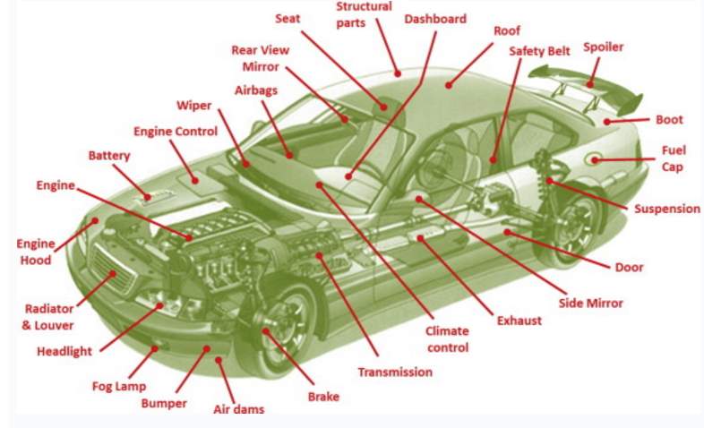
Figure 25 Automotive Application
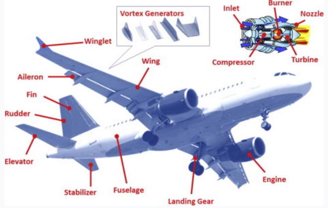
Figure 26 Aerospace applications
| Part Name | Quantity | Value |
| T210 Darlington transistor | 6 (Q1-6) | |
| Switch | 1 (S) | Input |
| Resistor | 2 (R1 & R3) | 5ohms |
| Resistor | 2 (R2 & R4) | 2ohms |
| Resistor | 1 (R7) | 2kohms |
| SMA wire | 1 (R) | 0.005” diameter |
| SMA wire | 1 (R) | 0.012” diameter |
| Power supply | 1 (P) | Max current 2A & voltage 5V |
Cite This Work
To export a reference to this article please select a referencing stye below:
Related Services
View all


Related Content
All TagsContent relating to: "Engineering"
Engineering is the application of scientific principles and mathematics to designing and building of structures, such as bridges or buildings, roads, machines etc. and includes a range of specialised fields.
Related Articles

DMCA / Removal Request
If you are the original writer of this dissertation and no longer wish to have your work published on the UKDiss.com website then please: