Hydrodynamic and Aerodynamic Forces on Floating Wind Turbine
Info: 4563 words (18 pages) Example Research Project
Published: 10th Jun 2021
Tagged: EngineeringEnergy
Title: A study of combined effect of aerodynamic and hydrodynamic forces in modular simulations of spar buoy floating wind turbine.
Summary of proposal: Combined interactions of aerodynamics and hydrodynamics helps to predict the structural response of the floating spar buoy platform due to the effect of unsteady aerodynamic loads acting on turbine blades.
The aim of the study is to create a mathematical model of wind turbine tower floating on sea and conduct modal analysis specifically for spar buoy foundation. This research will follow a systematic approach of literature review, load calculation, determining numerical data, modelling, applying boundary condition and analysing the results. Basic design data as well as technical assumptions will be made based upon actual model studied by NREL Hywind and land based mathematical models. MATLAB and Simulink software will be used for modelling and simulation to analyse the dynamic response of the model. Static analysis will be based on stochastic modelling to understand the probability of different environmental conditions.
Summary of national/community benefit: With the rising demand of clean and green energy production, wind energy serves as immense and inexhaustible source of power. Offshore wind turbine provides more advantages in terms of better turbulence and wind speed compared to onshore wind farms. Especially for country like Australia with maximum population density around coastal areas, offshore energy source can generate energy within nearby area of habitation.
Keywords: offshore Floating wind turbine, spar buoy, hydro-aerodynamics, ANSYS modelling, analysis
Supporting statement:
At Curtin university, during my study period in master’s of industrial engineering, I have been familiarized with various sub-branches of the field such as industrial modelling, supply chain and management, logistics and network optimisation, production planning, and mathematical models. Moreover, the skills learned as an industrial engineer is to consider some basic operations research techniques, and methods for solving optimisation problems as well as understand how to formulate any industrial problems in mathematical programming format.
Firstly, while undergoing my bachelor’s in mechanical engineering, I have observed and learned some of the key principles of mechanical engineering, which focus on the manufacturing and designing of different types of machines and its implementations in small scale, medium scale industries along with its usage in the large scale industries as well. On the other hand, the industrial engineering has taught me industrial profitability, economical feasibility and the overall manpower management. I have taken this opportunity of implementing the key learning from 2 streams of the engineering in a subject of mathematical modelling and analysis of floating wind turbine with spar bouy foundation, as a research proposal for my final assessment. I have learned Autocad, Solid works and ANASYS software in mechanical engineering, while LINGO and MATLAB in industrial engineering. I preformed mathematical model in MATLAB which is basically use for data analysis, modelling and simulating. My preference for choosing floating wind turbine over the conventional wind energy generation is based upon the presence of stronger winds at the water bodies when compared to the land and moreover, in Australia we have the largest coastline in the world and also being an island the country is surrounded by water bodies on all sides. Hence, going by my skills and the given geographical advantage the project proposal would be feasible and come true to it’s terms when we talk about the project benefits.
Background:
Due to increasing uses of fossil fuels, renewable energies are alternative way to maintain clean and green environment. The first concept of producing offshore floating wind turbine was suggested by
Heronemus (1972). But, it was not actually use in wind turbine industry until middle of year 1990. Because the conpect was new in offshore wind turbine indutry. Tong (1998) developed detail design and analysis of FLOAT(an offshore wind turbine) which is more suitable for spar bouy type floating wind turbine. In this view of floating wind turbine design, it was suggested the economic generation of electricity from wind power in offshore locations with considering water depth range between 100 and 300 m. Roalda, Jonkmanb, Robertsonb, & Chokania (2013) investigated the effect of second order hydrodynamics on offshore floating wind turbines based on revised technique based on used in oil and gas industry. In this case, two simulation tools are included for simulation of offshore floating wind turbine which are time domain tool FAST and frequency domain tool WAMIT respectively. These methods applied for spar bouy and tension leg platform types offshore floating wind turbines.
There are large number of techniques and analysis for flow simulations on wind turbines. A numerical simulation model using computational flow dynamics (CFD) presented for performance of aerodynamic wind turbine blade (Derakhshan & Tavaziani,2015). They introduced Raynolds average Navier Stokes equation as a solver for different tubulance models. The performance of tidal stream turbine can be evaluated by comparing numerical models between blade element momentum(BEM-CFD) technique and costal area model (Masters, et al., 2015). The static performance of a savonius style wind turbine can be investigated by direct numerical simulation (Ducoin, Shadloo, & Roy, 2017). A time-domain method was developed to simulate the VIV of marine risers based on a VIV forcing algorithm and the global coordinate based finite element method (Ma, Qiu, & Spencer, 2014). There are some challenges of offshore floating wind turbine due to simulation of aerodynamic, hydrodynamic and mooring line system (Schlipf, Cordle, Pereira, & Jonkman, 2011).
Aims:
The main objective of this research proposal is to study of combine effect of hydrodynamic and aerodynamic modular simulation of spar bouy foundation type floating wind turbine. In this research, Aerodynamic focrces of spar bouy foundation type wind turbine can be evaluated by using blade element momentum(BEM), computaional flow dynamics(CFD) and direct numerical simulation (DNS) techniques. In addition, morison’s equation is used to determine the resultant second order force generated due to the first order force exerted on the spar-buoy wind turbine structure by fluctuating ocean waves.
Significance:
This research proposal demonstrated here shows the effects of second-order hydrodynamic forces on the spar-buoy floating turbine. These second-order forces are generated due to wave load, exerted by ocean waves, on the base of floating wind turbine and are responsible for producing significant oscillation of the entire structure. As these oscillations can shake whole wind turbine, aerodynamic forces acting on the wind turbine blades also changes. Proposed research aids in understanding changes in turbine blade motion, while taking in to account both hydro and aero dynamic force changes occurred due to varying ocean wave frequencies and its amplitudes. As a result, it becomes convenient to simulate the flow of wind around the turbine blades more accurately using standard simulation methods such as BEM and CFD. These simulation results can assist in precisely calculating anticipated power generation amount with theses offshore turbines and ultimately reduce the subsequent economic losses.
- Aims and background:
- Background
With the increasing consumption of energy there is increase in the utility of fossil fuel in energy production. Apart from depleting fossil stock, the harmful effects of greenhouse gas emissions are more concerning at global environmental crisis. Hence, a clean energy source is more sorted as alternative for future energy requirements. The most opted renewable sources of energy are solar, wind and tidal. Ocean energy can be considered as the principal source of energy which subcategorizes into: wave, offshore wind and thermal gradient energy (Derakshan, Moghimi, & Motawej, 2018). Wind power is the vast inexhaustible source of energy which can be harnessed without emitting greenhouse gases. Land based wind turbines are more popular than floating wind turbines. The concept of locating the wind turbines amidst of ocean floating on the surface not only just solves the land issue but also offers strong winds that resides above sea water (Frye, Horvath, & Ndegwa, 2011). Europe was the first to begin this offshore project (Clarke, Fara, Dykes, Jodziewicz, & Watson, 2009) and since last decade European Union has broadened its commitment for sustainable energy production on to renewable sources (DECC, 2009) with offshore wind energy set to make largest contribution (DECC, 2010). To achieve the high target, approximately 33% of offshore wind farms are considered to be the potential resource (O’Keeffe & Haggett, 2012).
The foundation or the supporting structure of the offshore turbine mainly depends on the depth of water. According to this, three main support can be classified (as shown in Figure 1): shallow, transitional, and deep (Harriger, 2011). Turbine built in shallow water level has the foundation similar to those on land like a monopole. Although for transitional depth, the foundation is quite wide and supported to bottom for extra stiffness (Musial & Ram, 2010). The most challenging foundation is deep water turbine structure (water depth greater than 50 m) as the fixity of the support is sought from the buoyancy of the floated structures. This means that base of the turbine tower has to provide buoyancy to withstand the weight of the structure as well as rotational uncertainty caused by the wave motion (Lefebvre & Collu, 2012). A further classification of the (Tomasicchio, et al., 2018)
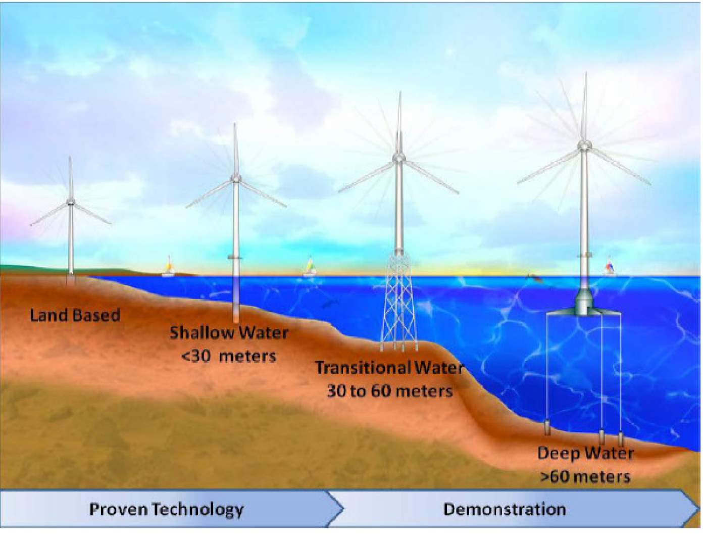
Figure 1 Different types of wind turbine as per the depth of water level (Rock, Parsons, & Werner, 2010)
1.2 Primary aims and outcomes
Well predictable rotor stress as well as wind flow can be calculated by mathematical modelling. The outcome of computational fluid dynamics and Morrison equation and their relationship with the modelling can provide a base for subsequent calculations involving superior environmental conditions like irregular wind flow and strong wave currents.
- Significance and innovation
- Significance
Experimenting the small-scale model of floating wind turbine into wave basin or an ocean field can provide the dynamic properties of the structure. This method is very expensive in terms of material cost, laboratory setup and equipment necessity for the experiment. However, simulation of the designed model can help in reducing risk, expenses, and uncertainties (Thanh & Dong-Hung, 2017) without limitations of scaling issues. The sophisticated dynamics of the combined coupled phenomena such as aero-hydro forces can be simulated and analysed better with computational tools.
2.2 Innovation
2.3 National benefit
- Approach and methodology
Dynamic analysis of floating wind turbines is complicated due to aerodynamics, hydrodynamics, and structural dynamics (Thanh & Dong-Hung, 2017). A precise analysis will account all the wave, current and wind load on the floating turbine and these loads have frequencies which can be compared to natural frequency of the structure (Lamei & Hayatdavoodi, 2020). This research uses existing literature to estimate the hydrodynamic and aerodynamic loads on the spar buoy floating wind turbine. Combined effect of these loads is validated by simulation in ANSYS model with all design data. This modal analysis and simulation will help to determine the critical frequency of the floating turbine for its structural reliability and integrity.
3.1 System configuration and properties
Basic design data as well as dimensional properties are based on literature review. Here, model under investigation is 5MW OC3 Hywind spar buoy (Jonkman, 2010) which was presented by National Renewable Energy Laboratory with the specifications of the floating system necessary for analysis and study of the spar buoy wind turbine. This will provide basic design data for: i) Design Spar Floating platform ii) Wind turbine and iii) Mooring cables. Configuration of spar buoy features 320m deep slender spar with three mooring lines. For precise understanding of only wave and wind effects, mooring dynamics is assumed to non-varying constant stress system so that simulation results offer dynamic response of the structure under the variable wind and wave forces.
3.2 Problem formulation and mathematical modelling
The mathematical modelling is mainly done to determine the load and predict the response of the structure under the combined effect of both loadings. 6 degrees of freedom such as: pitch, heave, yaw, sway, roll and surge will be considered for computing the design forces and stresses.
3.2.1 Aerodynamic load determination
Wind loads will be calculated by Computational fluid Dynamic (CFD) approach to include all the physical effects on the floating platform. (Thanh & Dong-Hung, 2017). This method helps in unsteady prediction of loads due to pitching and heaving of floating platform with the rotation of the blades (Thanh-Toan & Dong-Hyun , 2015). The mathematical computation methodology given by Wu & Nguyen (2017) will be considered for calculating turbulence of wind. The following mathematical model governed by Navier-Stokes equation about conservation of mass and momentum will be used to model the incompressible flow of wind and rotation of the blades:
Thus, total fluid stress tensor,
For simulation, k-ꞷ model will be adapted and solved for both: near and far turbulent quantities. This equation will be further discretised and solved for flow fields around rotors to get the range of stress values.
3.2.2 Wave-body characterization
The widely used common approach for computing hydrodynamics is Morrison equation (Roald, Jonkman, & Robertson, 2014). The hydrodynamic loads include linear hydrostatic load, wave load, incident currents, radiation from outgoing waves and nonlinear properties. Total hydrostatic load as per (Jonkman, 2010) can be given by equation:
g= gravitation acceleration,
V0= displaced volume of fluid
For wave modelling viscous drag has to be considered to find forces. Determination of force from wave kinematics can be given by following Morrison equation (Roald, Jonkman, & Robertson, 2014):
The first part of equation gives inertial force while second one gives viscous drag force.
Here, = mass coefficient
= drag coefficient
D= cylinder (tower) diameter
u= velocity and
= acceleration
Here, for slender spar turbine tower, vortex shredding frequency will be determined by following equation (Roald, Jonkman, & Robertson, 2014),
Where, S= Strouhal number
U=crossflow velocity
D= structural diameter
3.3 Finite element modelling (FEM) and simulation
The goal is to produce model, which is three-dimensional, solid structure which can be assigned element type and reflect all the assigned loads. Wind and wave responses on turbine tower will be modelled using ANSYS software using tetrahedral mesh elements with varying wave lengths. Mesh distribution will be done in in three parts: turbine, tower and lower body part which is below the floating surface.
Dynamic functional simulation of interaction between fluid and wind with structure will be done altogether with quasistatic mooring line model. High fidelity simulation of the floating turbine tower will include 6 Degrees of Freedom: 3 rotational and 3 translational as shown in Figure 2. As per Wu & Nguyen (2017), global coordinate system can be represented as (x0, y0, z0); tower coordinate system as (xt, yt, zt) and turbine-shaft coordinate system as (xs, ys, zs) for modelling purpose.
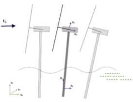
Figure 2 Operation of floating wind turbine under wave and wind conditions with coordinate system and degrees of freedom (Wu & Nguyen, 2017)
It is important to have high quality mesh to understand the complex flow regimes. Simulations will include both: steady as well as turbulent state of flow to get the optimum simulation response. The convergence criterion is set to 10-6 for all load conditions (Wu & Nguyen, 2017).
The modelling will be done in loop where it starts with aerodynamic and hydrodynamic forces calculated simultaneously with corresponding modules of mesh and fluid flow information updated accordingly. This loop will need to continue till it reaches convergence.
3.4 Results
The coupled aero-hydro dynamic numerical simulations of OC3 Hywind spar buoy wind turbine will be conducted with different load cases. Different values of wind speed, wave height, wave period and rotor speed (as shown in Table 1) will be considered for simulation process. These data (Table 2) will be plotted in a graph to get thrust against time. The fluctuation of aero-hydro forces will also cause heave and pitch with the governing loads.
|
Cases |
1 |
2 |
3 |
4 |
|
Wind speed |
||||
|
Rotor speed |
||||
|
Wave height |
||||
|
Wave period |
Table 1 Simulation at different load cases
|
Time |
t=120 s |
t=240 s |
t=360s |
|
Structural frequency |
|||
|
thrust |
Table 2 Simulation values of frequency and thrust at various time
Theoretical natural frequency of the structure will be calculated for various wind speed and wave data. This frequency can be compared against mode shapes which are under study. Mesh convergence analysis will be conducted to determine the maximum force and displacement acting at the specific time and the frequency of the structure critical with natural frequency.
3.5 Projected challenges
- Imposed boundary conditions may be critical
- Magnitude of errors are dependent on time and motion
- Load determination methods may require high computation performance and more time.
- Simulations result needs to be validated by experiments for more accuracy.
- Research ethics
- Timeline
The following timeline gives approximate time for completion of the project. The following Table 3 give the idea of the activities and the time required for their completion.
|
Activities |
Time (days) |
|
Topic selection, sorting project ideas, study, and literature review of the topic |
10 |
|
Calculation and collection of the data for project |
15 |
|
Load determination by mathematical modelling and generation of the load cases |
10 |
|
Generation of the Solidworks model in ANSYS, simulation of the model for analysis and obtaining results |
28 |
|
Discussion and analysis of the results |
7 |
|
Outlining gaps and creating thesis statement |
5 |
|
Drafting the paper and revision for final changes Formatting and editing of thesis for submission. |
10 |
Table 3 Project duration estimation
- Contingency plans
Some of the reasons which may delay or fail the project are as follows:
- Due to any technical glitch there could be a problem in running simulation or error in programming the turbine data.
- Unavailability of enough design parameters for modelling.
In the situation of operational error in software, another backup simulation software like ABAQUS or SCILAB will be kept available so that project does not delay due to lack of modelling capability. For data collection, I will most certainly use Curtin library search and refer to the peer reviewed papers.
- References
Cite This Work
To export a reference to this article please select a referencing stye below:
Related Services
View all


Related Content
All TagsContent relating to: "Energy"
Energy regards the power derived from a fuel source such as electricity or gas that can do work such as provide light or heat. Energy sources can be non-renewable such as fossil fuels or nuclear, or renewable such as solar, wind, hydro or geothermal. Renewable energies are also known as green energy with reference to the environmental benefits they provide.
Related Articles

DMCA / Removal Request
If you are the original writer of this research project and no longer wish to have your work published on the UKDiss.com website then please: