3D Printing for Medical Simulation of Airway Emergencies in Paediatric Anaesthesia
Info: 20751 words (83 pages) Dissertation
Published: 24th Jan 2022
Table of Contents
Click to expand Table of Contents
1 Research Rationale
2 Literature Review
2.1 The Paediatric Airway
2.1.1 Airway anatomy
2.1.2 Anatomical differences
2.1.3 Physiological Differences
2.1.4 Airway management in children
2.1.4.1 Bag valve mask
2.1.4.2 Oral airways
2.1.4.3 Supraglotic airways
2.1.4.4 Endotracheal tube
2.1.5 The paediatric difficult airway
2.1.6 Management of difficult airway in children
2.1.7 Can’t Intubate, Can’t Oxygenate (CICO)
2.2 Additive Manufacturing
2.2.1 Introduction
2.2.2 Layer by Layer Concept
2.2.3 Additive manufacturing
2.2.3.1 Stereolithography (SL)
2.2.3.2 Solid ground curing (SGC)
2.2.3.3 Digital light processing printing (DLP)
2.2.3.4 Selective laser sintering (SLS)
2.2.3.5 Three-dimension printing (3D)
2.2.3.6 Laminated object manufacture (LOM)
2.2.3.7 Multi-jet modelling (MJM)
2.2.3.8 Fused filament fabrication/fused deposition modelling (FFF/FDM)
2.2.4 Print Materials
2.2.4.1 Common filaments
2.2.4.1.1 Polylactic Acid (PLA)
2.2.4.1.2 Acrylonitrile Butadiene Styrene (ABS)
2.2.4.1.3 Polyethylene Terephthalate Glycol (PETG)
2.2.4.1.4 Polyamide (PA)
2.2.4.2 Specialist filaments
2.2.4.2.1 Characteristic
2.2.5 Use of 3d printing in medicine
2.3 Simulation
2.3.1 Background
2.3.2 CICO Simulators
2.3.2.1 Self-build CICO trainers
2.3.2.1.1 Ultimate Cricothyrotomy Trainer
2.3.2.1.2 AmboFoam Trainer
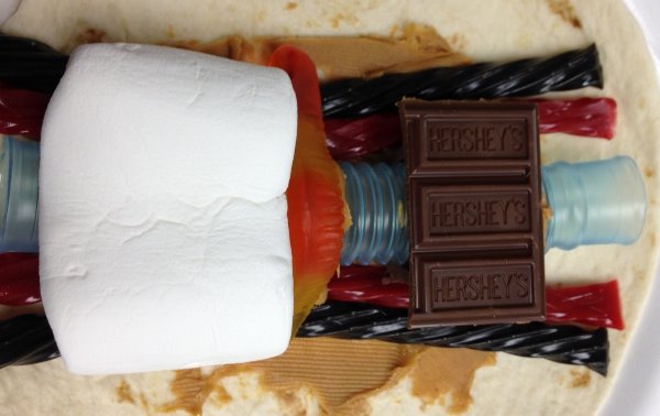
2.3.2.1.3 Edible trainer
2.3.2.2 Commercial CICO trainers
2.3.2.2.1 Nasco Trainer
2.3.2.2.2 SynDaver™ Cricothyrotomy Trainer
2.3.2.2.3 SimulaidsTM Cricothyrotomy Simulator
2.3.2.2.4 RouillyTM CICO Trainer
2.3.2.2.5 VBMTM CICO trainer
3 Aims and Objectives
4 Materials and Methodology
4.1 Materials
4.1.1 DICOM Viewer
4.1.2 Mesh modelling
4.1.3 3D Modelling CAD
4.1.4 G-code generation software
4.2 Printer
4.3 Methodology
4.3.1.1 Torso model
4.3.1.2 Airway simulation module
4.3.1.3 Cricothyroid membrane
4.3.1.4 Continuous skin construction
4.3.2 Model testing
4.3.3 Cost calculation
5 Results
5.1 Torso model
5.2 Airway Module
5.3 Continuous skin layer
5.4 Infant CICO trainer evaluation
5.4.1 Evaluation of palpation of anatomical features
5.4.2 Evaluation of kinaesthetic properties
5.4.3 Overall satisfaction with the infant CICO trainer
5.4.4 Cost
6 Discussion
6.1 Torso model
6.2 The airway module
6.3 Continuous skin layer
6.4 Infant CICO trainer evaluation
6.5 Cost evaluation
7 Further Work
8 Conclusion
9 Appendix
9.1 Appendix 1
9.2 Appendix 2
10 References
11 Notice of submission: postgraduate taught degrees
Table of Figures
Figure 2‑1 Airway anatomy. Adapted from http://teachmeanatomy.info
Figure 2‑2. Airway cartilages. Adapted from http://teachmeanatomy.info
Figure 2‑3. Cross-sectional shape of upper airways. Adapted from (Strohl et al. 2012)
Figure 2‑4 Methods of airway management
Figure 2‑5. The LMA in situ. Adapted from www.i-gel.com
Figure 2‑6. Grades of intubation Adapted from (CORMACK and LEHANE 1984)
Figure 2‑7. Narrow bore cricothyroidotomy. Adapted from (Pirotte and Sarwark 2014)
Figure 2‑8. Classification of 3D printing modalities. Adapted from (Pham and Gault 1998)
Figure 2‑9. Stereolithography. Adapted from (Pham and Gault 1998)
Figure 2‑10. Solid ground curing. Adapted from (Yan and Gu 1996)
Figure 2‑11. Selective laser sintering Adapted from (Pham and Gault 1998)
Figure 2‑12 Multijet printer. Adapted from (Stansbury and Idacavage 2016)
Figure 2‑13. Fused deposition modelling. Adapted from (Stansbury and Idacavage 2016)
Figure 2‑14. Comparison of Porolay pre (left) and post (right) rinse. Adapted from (Krassenstein 2014)
Figure 4‑1. Sintron Prussa Mk2 FDM printer
Figure 4‑2. Volume rendering of infant.
Figure 4‑3. Post Laplacian smoothing and voxel removal in MeshLab.
Figure 4‑4. (A) Child pre-production (B) Post head extension, airway chamber cut and slimmed for printing.
Figure 4‑5. Sagittal (A), axial (B) and coronal (C) views of the infant airway.
Figure 4‑6. (A) Airway volume rendering (B) airway volume rendering with MRI overlay
Figure 4‑7. Airway module with MRI as canvas and airway volume rendering in Fusion 360
Figure 4‑8. Airway module
Figure 5‑1. Lateral view of infant CICO trainer torso.
Figure 5‑2. Airway module prints
Figure 5‑3. Completed airway module and continuous skin mould with increasing percentage of deadener LV
1 Research Rationale
Airway management is the corner stone of anaesthetic practice and while the majority of airway interventions in the paediatric population are uncomplicated, instances can arise where the ability to manage the airway can be compromised (Prunty et al. 2015). This situation can progress to become a “can’t intubate can’t oxygenate” (CICO) scenario. A CICO scenario is an emergency and requires a set of potentially lifesaving skills to be performed. The skills of a CICO scenario aim to restore the supply of oxygen to the lungs via an infraglottic airway rescue technique, by-passing the upper airways and delivering oxygen directly to the trachea and lungs. These skills will extend the time available for securing a definitive airway and prevent secondary organ damage, namely hypoxia that can ensue. It is imperative that the infraglottic airway rescue technique is deployed as soon and efficiently as possible after a CICO situation has been declared to minimise end organ damage. The skill set of a CICO scenario, when performed on an adult are difficult and stressful, the challenge in the infant or child is further compounded.
Paediatric patients can present to any hospital as an emergency requiring airway interventions, often non-specialist centres with non-paediatric anaesthetists. A resulting CICO scenario could occur in the hands of a non-paediatric specialist, adding further stressors to an already stressful environment. Therefore, it is an important skill to remain proficient and confident in using. Currently few simulation tools are available for the paediatric patient. Therefore, a simple, affordable open source simulation device, specific to the paediatric population is required for the training of anaesthetists. This need was highlighted by the Royal College of Anaesthetists in the Fourth National Audit Project (NAP4). Recent technological advances in 3D printing have resulted in increased use of this technology in the medical practice, coupled with its increasing availability and decreasing cost makes it a desirable technology to investigate for production of an infant airway trainer.
2 Literature Review
2.1 The Paediatric Airway
This section introduces the anatomy and management of the airway. It discusses the challenges faced in managing the paediatric airway.
2.1.1 Airway anatomy
The mouth and nose define the entrance to the airway. The nasal cavity becomes the nasopharynx, the oral cavity the hypopharynx. The Nasopharynx and oropharynx merge to become the hypopharynx extending from the epiglottis to the cricoid cartilage. The epiglottis is an anterior structure that covers the opening of the glottis (vocal cords) and acts to direct food matter away from the airway during swallowing. The oesophagus is seen posteriorly to the vocal cords.

The larynx lies anteriorly to the oesophagus and on the skin is felt as the thyroid cartilage (Addams apple). The larynx is defined anteriorly by the hyoid bone, thyroid cartilage, cricothyroid membrane, and the cricoid cartilage. The arytenoid cartilages form the posterior aspect of the laryngeal inlet and are important landmarks as these are the first structures visualized as the epiglottis is lifted from in front of the vocal cords during laryngoscopy, and may be the only part of the glottis visualized in some patients and thus serve as an important landmark for intubation. The vocal cords cover the entrance to the trachea, between the vocal cords and the first tracheal ring lies the cricoid cartilage. The cricoid is signet ring shaped, with its large base being posterior and pressing against the oesophagus. The tracheal rings are C shaped, with the open portion against the oesophagus to allow expansion of the oesophagus as a food bolus passes.
Figure 2‑1 Airway anatomy. Adapted from http://teachmeanatomy.info
 The trachea originates at the caudal ring of the cricoid cartilage, ending inferiorly at the carina, the bifurcation of the trachea into the left and right main bronchus. Within the neck the trachea lies only a few millimetres below the skin. The skin is formed of three layers, the epidermis, dermis and hypodermis. The epidermis acts to provides a waterproof barrier, below, the dermis contains connective tissue, hair follicles, and sweat glands. The dermis is the toughest layer. The deeper subcutaneous tissue (hypodermis) is made of fat and connective tissue.
2.1.2 Anatomical differences
The paediatric airway differs in many ways from the adult airway, although many anatomical structures are similar their orientation or size are significantly different. These differences are most pronounced in neonates and infants under 12 months of age (Harless et al. 2014). The differences are summarised in Table 2‑1.
| Anatomy | Child | Adult |
| Tongue | Large | Small |
| Epiglottis shape | Floppy, omega shaped | Firm, flatter |
| Epiglottis Level | Level of C3 – C4 | Level of C5 – C6 |
| Trachea | Smaller, shorter | Wider, longer |
| Larynx Shape | Funnel | Straight |
| Larynx Position | Angles posteriorly away from glottis | Straight up and down |
| Narrowest Point | Cricoid | At vocal cords |
Table 2‑1. Child airway anatomy vs adult.
The most striking anatomical difference is the large head size relative to the body with a prominent occiput in the infant. The tongue is larger and the mandible shorter, coupled with larger adenoids and tonsils. This reduces the space within the oral cavity and explains why infants are nasal breathers until the age of 5 months. The hypopharynx is also relatively smaller than the adult. The larynx is higher in children, with the upper glotic structures lying at the level of the mandible. The cricoid cartilage lies at the level of the 4th cervical vertebra in the adult it lies at the 6th cervical vertebra. The epiglottis is larger and U shaped and can obscure the opening to the glottis.
The shape of the upper airways is classically thought of as being spherical; however the cross-sectional shape of the airway varies throughout the upper airways as shown in Figure 2‑3 (Strohl et al. 2012). The upper airway, defined as the air passages from the mouth and nose to the first tracheal ring (Remmers et al. 1990). Furthermore, the shape of the infant airway is described as funnel shaped, the cricoid cartilage being the narrowest part of the airway (Pinnock et al. 1999). In adults, the vocal cords are narrower and hence the requirement for an ET tube with a cuff is required to gain a seal.

Figure 2‑3. Cross-sectional shape of upper airways. Adapted from (Strohl et al. 2012)
The paediatric airways are described as more pliable and prone to collapse in negative pressure situations, such as increased negative intrathoracic pressure. The young’s modulus of neonatal cartilage has not been recorded to date, while the Young’s modulus of tracheal cartilages of young adults is reported in the range 2.5–7.7 MPa (Roberts et al. 1997). This has been calculated by bending of whole tracheal cartilage ring and applying curved beam theory. The total modulus of the airway wall is affected by the elasticity of several other structural elements, including muscular, non-muscular, and mucosal structures that decrease the moduli (Strohl et al. 2012). Neonates and infants lack a functional cricothyroid membrane and the gap between the cricoid and the thyroid cartilage does not allow passage of a 2.0-mm ID tracheal tube in the neonate (Navsa et al. 2005).
2.1.3 Physiological Differences
The infant has several physiological differences to adults. The differences include a higher metabolic rate and smaller reserve of oxygen within the lungs. The high metabolic rate refers to the rate of consumption of oxygen from the blood. The infant can extract up to 7 -9 mL/kg/min compared with 3 mL/ kg/min in the adult (McNiece and Dierdorf 2004; Navaratnarajah and Black 2012). At the end of exhalation adults have a volume of residual air within the lungs, this acts as a store of oxygen. In children, this store, termed functional residual capacity (FRC) is significantly reduced and thus, the reserve of oxygen reduced. These differences culminate in children desaturating quicker when apnoeic. Desaturation refers to the reduced blood oxygen concentration (
2.1.4 Airway management in children
Managing the paediatric airway is a pivotal role for the anaesthetist, with the aim of supporting or taking control of ventilation. Ventilation refers to the passage of oxygen to the alveoli and the removal of waste products from the alveoli (Hall 2010). The airway can be supported by the anaesthetist utilising a range of devices as shown in Figure 2‑3.

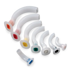
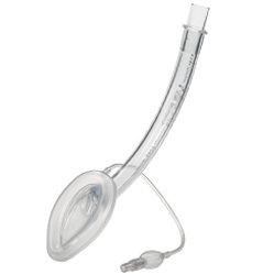
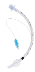
A B C D
A) Bag valve mask B) Oral air way C) Supraglotic airway D) Endotracheal tube
Figure 2‑4 Methods of airway management
2.1.4.1 Bag valve mask
The simplest and most import means of ventilating a patient. The device is available in many forms, but allows air supplemented with oxygen to be delivered to the patient through assisted ventilation. The bag is squeezed and air is forced under positive pressure through the airways into the lungs.
2.1.4.2 Oral airways
A common cause of difficult ventilation is obstruction of the airway by the tongue falling into the back of the airway and obstructing the passage of air from the oral pharynx into the larynx. This can be overcome using a jaw trust, pulling the tongue forward or by inserting an oral airway.
2.1.4.3 Supraglotic airways
Supraglotic airways (SGA), as their name alludes, sit above the glottis (vocal cords) and maintains the patency of the airway. These devices are not considered a secure airway as isolation of the airway from the gastric track cannot be guaranteed (Figure 2‑5). SGA are not appropriate for all patients, especially young or critically ill children. They have a role in maintaining the airway for short procedures and play a pivotal role in the algorithm for the management of difficult ventilation, intubation or both. They are associated with a very low failure rate of 0.86% in children (Fiadjoe et al. 2016).


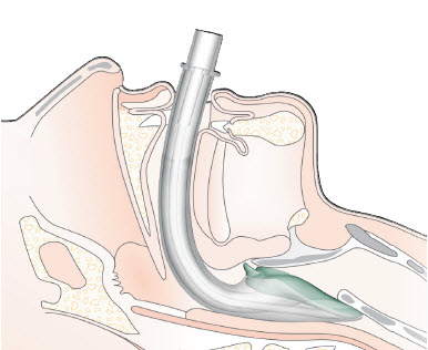
Figure 2‑5. The LMA in situ. Adapted from www.i-gel.com
LMA
Epiglottis
Vocal cords
Trachea
Oesophagus
2.1.4.4 Endotracheal tube
The endotracheal tube (ETT) is considered the gold standard for airway management. The ETT is passed through the mouth or nose and enters the trachea via the vocal cords. In adult and larger children, a balloon (cuff) is inflated in the trachea to form a seal, in children uncuffed tubes are often used as the cricoid cartilage forms a seal, owing to it being the narrowest part of the airway. The ETT is a definitive airway, isolating the airway and allowing complete control of ventilation. The ETT is used for long procedures or the critically ill.
The view achieved when intubation is used as a marker of difficulty of intubation and was first described by Cormack and Lehane (1984). The 4-point scale I – IV is shown in Figure 2‑6. A grade I or II view is considered as a normal, uneventful intubation. A grade III or IV view are considered as challenging intubations.
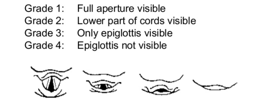
I II III IV
Figure 2‑6. Grades of intubation Adapted from (CORMACK and LEHANE 1984)
2.1.5 The paediatric difficult airway
In recent years, the NHS has seen the centralisation of paediatric services. Anaesthetic practice in district general hospitals (DGHs) has seen a decrease in the management of children below four years of age for elective surgery, however, children can present as emergencies via the A&E departments at any age. These emergency presentations can require airway interventions in many of the hospitals that do not offer elective services to younger children.
The Royal College of Anaesthetists (RCOA) Forth National Audit Project (NAP4) highlights several key points that could result in children presenting to DGHs entering a hospital where anaesthetists have less paediatric experience than a decade ago. There is no evidence to suggest that these changes have impacted the delivery of emergency anaesthetic skills in the DGHs, however, should the child need immediate airway management it is likely that the anaesthetists, will have less current experience in management of sick children and their airways. The anaesthetists in these hospitals are skilled in the management of the adult airway, however, children are not small adults as shown by the presence of the significant anatomical and physiological differences (Harless et al. 2014). A different approach to the management of the neonate and infant airway is required. These features, coupled with the stresses of an emergency situation can lead to an increased risk of difficulty with airway management within this age group (Heinrich et al. 2012).
The unanticipated difficult or failed airway intervention in otherwise healthy children is thankfully rare. Failure to secure the airway, however, remains one of the main causes of morbidity and mortality in paediatric anaesthesia (Jagannathan et al. 2016). A difficult airway is defined as an airway where holding a mask or bag-vale ventilation is difficult using standard equipment. A difficult intubation is defined as one requiring three or more attempts with standard equipment or the use of advanced airway equipment from the outset (Navaratnarajah and Black 2012).
NAP4 investigated all reported episodes of major airway events, such as failed intubation, over a 12-month period in all hospitals within the UK. It highlighted 13 cases relating to under 16 year olds representing 7% of all airway events reported. Most paediatric cases reported to NAP 4 (11 of 13) were anaesthesia-related and involved young children (3 under one year old and 4 under the age of four years). These findings are supported by Heinrich (2012) who found the incidence of a difficult intubation in children under 16 years, classed as a Cormack and Lehane grade III and IV was shown to be 1.35% in a study of 11,219 paediatric anaesthetics. In children under 5 years the incidence is 4.7% (Heinrich et al. 2012). The incidence of difficult intubation among specific groups of children has been shown to be higher, in children under 6 months of age with cleft palate the incidence is 7% (Katz 2012). Tragically three of the reported cases reported to NAP4 resulted in the death of a child, two of the deaths related to difficult intubation. Four of the other cases involved difficult or impossible intubation leading to potential morbidity (Katz 2012). The NAP4 report has highlighted a number of key learning points, one which is that found a high rate of failure for needle cricothyroidotomy in adults and the likelihood that the procedure in children will be even more demanding (Katz 2012).
A recent multicentre study of 1018 cases of airway management in children with difficult airway management has shown that tracheal intubation was unachievable in 2% of these cases (Fiadjoe et al. 2016). Complication from difficult intubation can be wide ranging, from transient hypoxia, the most common complication to cardiac arrest and death. At least one complication was observed in 20% of children with a difficult intubation (Jagannathan et al. 2016)
Clinical assessment of the airway can identify features of the airway associated with an increased risk of a difficult intubation. There are individual morphometric, functional and anatomical predictors of difficult intubation. These features can include among others, obesity, micrognathia (small mouth), macroglossia (large tounge), dental abnormalities (poor dentition, large teeth), a narrow face, a high arched palate, a short neck and cranio-facial dysmorphism are associated with difficult intubation conditions (Frei and Ummenhofer 1996). In children, difficult intubations can also be associated with many genetic syndromes that display cranio-facial dysmorphism as shown in Table 2‑2.
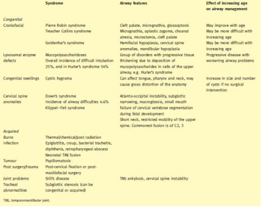
Table 2‑2 Conditions associated with difficulties in airway management. Adapted from (Navaratnarajah and Black 2012)
2.1.6 Management of difficult airway in children
When an airway is identified as being potentially difficult, time is available to devise a suitable plan to minimise the risk associated with its management to a suitable level. Features of the plan may include the use of specialist intubating equipment including; fibre optic scopes, video laryngoscopes or elective tracheostomy.
This dissertation will focus on the unanticipated difficult airway scenario. When an unexpected difficult ventilation or intubation has been encountered, protocols have been developed to guide the anaesthetist to re-establish oxygenation. Protocols have been devised by several societies, the leading society on the management of difficult airways is the Difficult Airway Society (DAS). DAS originally produced and published algorithms for the adult population, later, and in partnership with the Association of Paediatric Anaesthetists of Great Britain and Ireland (APA) these algorithms have been adapted for children over 1 year of age. Currently there is no agreed consensus for neonates and infants under 1 year of age.
The APA algorithms address management of both difficult mask ventilation and difficult intubation. The algorithms aim to restore oxygenation of the child in a stepwise approach, each of the three steps A, B and C introduces a new technique. The flow charts are shown in appendix 1. The final part of the difficult intubation algorithm is declared as a can’t intubate can’t ventilate (CICV). This terminology has now been superseded with the can’t intubate can’t oxygenate (CICO) terminology, new guidelines are awaited from APA with updated terminology. As previously described ventilation refers to the movement of oxygen into and the removal of waste products from the lungs. The removal of waste products, namely carbon dioxide (CO2) is not an immediate threat to life. The insufflation of oxygen alone can delay the onset of hypoxia allowing time for further procedures to be performed to secure an airway for ventilation.
2.1.7 Can’t Intubate, Can’t Oxygenate (CICO)
The evidence regarding the management of a CICO scenario in the paediatric population is limited, conflicting, and often extrapolated from adult studies (Stacey et al. 2012). Debate surrounds the foremost approach to front of neck access (FONA) with currently four approaches described for FONA. These techniques are narrow-bore needle cricothyroidotomy, wide-bore needle cricothyroidotomy, scalpel technique or surgical tracheostomy. All techniques, bar the surgical tracheostomy, gain access to the airways via a subglottic approach via the cricothyroid membrane.
The APA guidelines advocates the use of a needle cricothyroidotomy, this is in line with the evidence from the Advanced Life Support Group (ALSG) and American Society of Anaesthesiologists (Black et al. 2015; APLS 2011; Apfelbaum et al. 2013). The NAP4 evidence shows the incidence of failure for this procedure was high in the adult population and the NAP4 authors postulate that among the paediatric population the failure rate would be greater (Katz 2012). The reasons for failure were numerous and disparate. Reasons for failure included poorly designed equipment, malfunctioning equipment, use of equipment not designed for this purpose, poorly used equipment, poor insertion technique or use of the wrong method of ventilation after insertion (Katz 2012). Stacey (2012) has shown that in the rabbit model, used to simulate the paediatric airway the success rate is greater than that suggested in NAP4. Further evidence from XXX has shown that the advantages of the other techniques in the adult are not preserved in the young child and thus the narrow-bore needle cricothyroidotomy is the procedure of choice in the neonate or young infant.
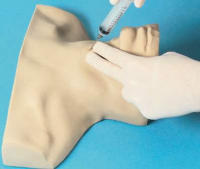
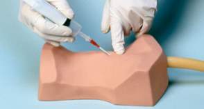
The narrow-bore needle cricothyroidotomy uses a needle and cannula technique. The technique is a single person, two handed procedure and is implemented when a CICO scenario is declared. The first step requires the head to be extended to allow identification of the laryngeal prominence, moving the hand in a caudal direction to locate the cricothyroid membrane. In the neonate, the laryngeal prominence is not well developed and the cricothyroid membrane can be identified by moving up the tracheal rings. Next a needle and cannula are passed at 30-40 degrees in a caudal direction connected to a 5ml syringe with 3 mls of water. The syringe is constantly aspirated until air bubbles are seen, this identifies entry to the airway. The cannula is advanced off the needle into the airway and needle withdrawn. It is imperative during this stage that the needle is stabilised by the aspirating hand to prevent further advancement of the needle or withdrawal out of the airway by resting the hand on the patients chin. The cannula connected to a high-pressure wall oxygen outlet and oxygen insufflated until the chest rises (Figure 2‑7) (Pirotte and Sarwark 2014).
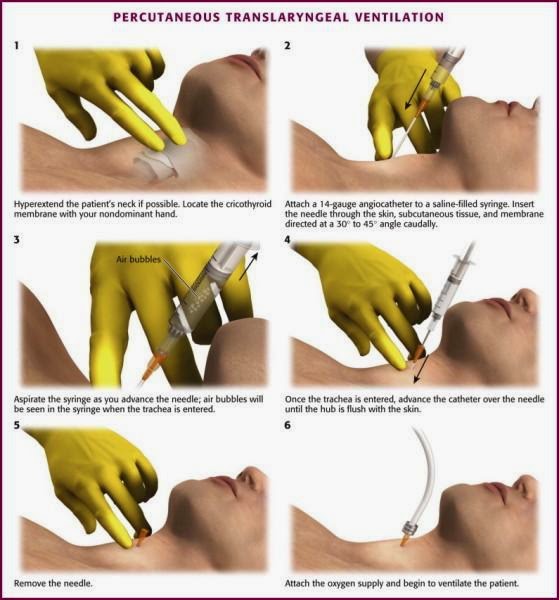
Figure 2‑7. Narrow bore cricothyroidotomy. Adapted from (Pirotte and Sarwark 2014)
A CICO event in the adult population is a relatively rare and terrifying incident for any anaesthetist. To consider this situation and its management in the paediatric population adds significantly to the difficulties and stressors encountered and may increase failure rates. Nap 4 has recommended that optimum training in cricothyroidotomy insertion and ventilation, use of equipment specifically designed for this use and regular practice with such equipment seem logical goals to pursue in trying to minimise this failure rate. This approach is further supported by the research of Sabato (2016) that states that CICO is a “rarely practised procedure”.
2.2 Additive Manufacturing
This section introduces the general concept of rapid prototyping (RP) and overviews the range of processes employed and introduces the concept of three-dimensional printing within rapid prototyping and the associated processes.
2.2.1 Introduction
Rapid prototyping (RP) embraces a range of technologies for producing accurate three-dimensional (3D) parts directly from computer-aided design models (Pham and Gault 1998). Various processes have been employed to add and subtract materials, this has been evident since the industrial revolution and these processes included cutting, carving, grinding, milling and etching. The early forms of Subtractive methods, especially milling, have been readily automated, milling gained traction as the first fully digital production technique since the 1960’s – 70’s with the use of Computer Numerical Control (CNC) (Carlsson 1984). Rapid prototyping in the early 1980’s used milling machines to ‘carve’ each slice of a model from a solid material. The limitation of milling, even with the use of five-axis machines coupled with the increasing complexity demanded by industry led to the development of the field of RP (McGurk et al. 1997).
2.2.2 Layer by Layer Concept
The term 3D printing which is increasingly used to describe the process of rapid prototyping has its origins in the late 1980’s. 3D printing is a method of manufacturing in which materials, such as plastic, are deposited onto one another in layers to produce a 3D object (Stansbury and Idacavage 2016). The first patent for 3D printing as awarded in 1986 to Charles Hull for creating 3D objects from light cured resin, a process called stereolithography (SL) (Bill et al. 1995). Further 3D printing technologies and processes have since emerged, including selective laser sintering (SLS), 3D printing (3DP), multi-jet printing (MJP) and fused deposition modelling (FDM). A 3D printer serves to create a solid object with height width and depth derived from a digital model.
3D printing techniques can be classified into three broad categories – forming, subtractive or additive manufacturing (Stansbury and Idacavage 2016). Forming involves the reshaping of a work piece without reducing or adding material for example vacuum forming. Subtractive manufacturing which for example utilises CNC milling to remove material. Additive manufacturing involves, as the name suggests the addition of materials to form the final object.
2.2.3 Additive manufacturing
Gibson et al. (2010) describes additive manufacturing as a range of technologies capable of translating virtual solid model data into physical models in a quick and easy process, where the object is broken into 2D cross sections of a finite thickness and used by the 3D printer to construct the final object by adding them together in a layer-by-layer sequence. The range of additive process can be subdivided as shown in fFigure 2‑8 (Pham and Gault 1998).
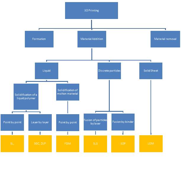
Figure 2‑8. Classification of 3D printing modalities. Adapted from (Pham and Gault 1998)
2.2.3.1 Stereolithography (SL)
SL produces 3D objects from a bath of a photosensitive polymer, which when exposed to ultraviolet (UV) light forms a solid mass. The polymer used is either acrylate photopolymer or epoxy resin liquid. The low-powered UV laser draws the layer pattern and once complete it is lowered just below the surface and the process is repeated until all layers of the object are formed (Figure 2‑9). The colour can be varied using additives and the resin is cured further in a UV oven (Melchels et al. 2010).
Despite the development of many other techniques stereolithography remains a powerful and versatile form of 3D printing, owing to its high fabrication accuracy of under 0.5% (Yan and Gu 1996). SL has been used extensively in the medical fields, it has been used to produce facial fractures to allow surgical planning by maxillofacial surgeons (James et al. 1998).
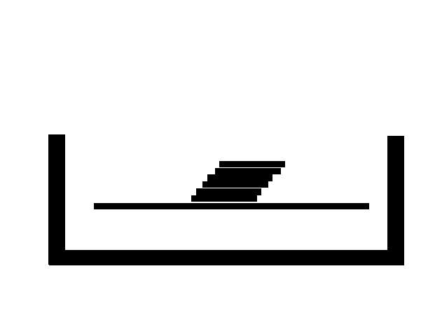
2.2.3.2 Solid ground curing (SGC)
In SGC a photopolymer is exposed to UV light, the laid pattern is developed onto a glass sheet that acts as a mask to the polymer below. The polymer that is masked will not polymerise into a solid. After each layer the unpolymerized polymer is washed away and replaced with wax that is milled flat and a new layer of polymer laid down and the process repeated (Figure 2‑10) (Gu et al. 2001).
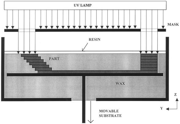
Figure 2‑10. Solid ground curing. Adapted from (Yan and Gu 1996)
2.2.3.3 Digital light processing printing (DLP)
DLP printers also produce objects from a vat of polymer. These printers can use commercially available DLP projectors. When used with liquid polymers such as standard blend (FunToDo, Netherlands) cure time of 0.5 seconds for 0.02mm layers are achieved with a light source of around 240 Watts and wavelengths of 225nm to the near/visible wavelengths of 415nm (FunToDo 2017). The layer is created and the object moved below the surface and the next layer projected.
2.2.3.4 Selective laser sintering (SLS)
SLS developed by Carl Deckard and Joseph Beaman at the Mechanical Engineering Department of University of Texas at Austin utilises similar principles to that of SL, the UV laser is replaced by a high-power laser carbon-dioxide laser(25-50W) and the resin by powder. The laser traces the layer in the powder, sintering or melting it to form a solid layer (Yan and Gu 1996). The fused layer is lowered and a further layer of powder added and the process repeated, fusing the new layer to the previous. The powder can be formed of polycarbonate, poly vinyl chloride (PVC), acrylonitrile butadine styrene (ABS), casting wax or glass filled composite nylon (Yan and Gu 1996). The powder can contain a low-carbon steel mixed with the powder that forms a ‘green state’ object, this is further fired to remove the powder and allow the steel to sinter together (McGurk et al. 1997). SLS has advantages over SL, other than the range of materials available the powder of each layer acts as a support for the next. Thus, predesigned supports are not required like those in SL.
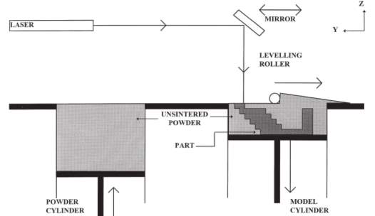
Figure 2‑11 . Selective laser sintering Adapted from (Pham and Gault 1998)
2.2.3.5 Three-dimension printing (3D)
3D printing was developed at the Massachusetts Institute of Technology by Sachs and Cima and was original coined with the term ‘3D printing’, this term is now synonymous with many forms of rapid prototyping (Hofmann 2014). It uses a powder based substrate spread in thin layers and fused together, fusion is controlled by a binder dropped from a print head (Yan and Gu 1996). After each layer is finished, it is lowered and further powder added. The final object often requires post production heat treatment to further enhance the bonding power of the binder (McGurk et al. 1997). The range of materials available are increasing, along with the use of multiple print heads to produce different colours.
2.2.3.6 Laminated object manufacture (LOM)
LOM machines receive the build material via a roll. The material is activated by a heated roller that adheres it to the layer below. Once adhered a laser, calibrated to only cut the thickness of the material cuts the layer shape. Waste material remains, acting as a support. Post production the waste is removed.
2.2.3.7 Multi-jet modelling (MJM)
Multi-Jet (or PolyJet) printing utilizes a photopolymer, often acrylic based that is UV-cured. This technique can produce smooth parts with highly complex geometries. Jetting‐based additive processes are gaining popularity because of their high speed of operation, accuracy and high resolution. As a result of the thin build layers of 20 μm or less post production finishing is not required (Stansbury and Idacavage 2016). The build surface can be supported by a wax or other gel-like supporting material which can be co-deposited for subsequent removed (Fahad et al. 2013). The use of multiple print heads allows for different colours or even different building materials with differing modulus properties to different parts of the build object (Hofmann 2014).
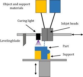
Figure 2‑12 Multijet printer. Adapted from (Stansbury and Idacavage 2016)
2.2.3.8 Fused filament fabrication/fused deposition modelling (FFF/FDM)
FDM machine consists of a movable print head that deposits molten substrate onto a printing bed. The material to be extruded is fed, as a solid filament into an extruder, heated to within a few degrees of its melting point with the hot end of the extruder and extruded through a fine bore nozzle. The plastic is extruded in a controlled X–Y-movement onto the previous layer of the build, such that as it solidifies a cold weld forms with the layer below (Pham and Gault 1998). Once a layer is complete the print head is raised and the next layer is deposited in a repeating cycle (Figure 2‑13).
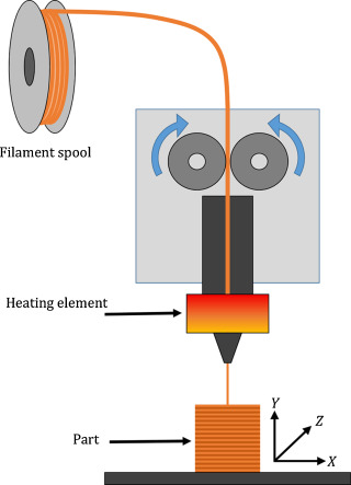
Figure 2‑13. Fused deposition modelling. Adapted from (Stansbury and Idacavage 2016)
There has been an influx of affordable 3D printers, a large proportion being FDM. One of the most influential printers in the rise of FDM in the home printing market is the RepRap machine, an open-source venture accomplished by volunteers throughout the world (Bowyer 2014). Machines of this style can be purchased in kit form for under £200 and resulted in more than several thousand machines worldwide (Alssabbagh et al. 2017). The latest FDM system includes multiple print heads, which allows for multiple materials to be printed in the same work piece (Josef 2017). FDM machines cannot intimately blend colours or materials as in multi-jet print technology (Stansbury and Idacavage 2016).
FDM printers can achieve excellent print qualities. Problems associated with FDM printers include warping, bridging and poor bed adhesion. Warping occurs where the base of the print object lifts upwards and is no longer level with the print platform. This can be overcome with the use of a heated build platform or the use of adhesive to improve first layer adhesion. Bridging is caused by strings of plastic between parts of the model this can be improved by enabling retraction. Retraction cause the filament to be withdrawn from the print head between print areas, this can increase print times. Bridging is more evident with flexible filaments (Jennings 2017).
2.2.4 Print Materials
An increasing number of commercial filaments are now available for FDM printers. The range of filaments available to FDM machines was one of the original limiting factors (Fillaments.ca 2014). Filaments available include Polylactic Acid (PLA), Acrylonitrile Butadiene Styrene (ABS), Polyethylene Terephthalate Glycol (PETG), Thermoplastic Elastomers (TPE) and Polyamide (PA). There are a range of specialist filaments with unique characteristics or with materials, such as carbon fibre or wood embedded within a carrier filaments. PLA and ABS are the most commonly used materials in the 3D printing industries. Most of these 3D materials come in filamentous shapes and are available in diameters of 1.75 mm and 3 mm (MatterHackers, 2015).
2.2.4.1 Common filaments
2.2.4.1.1 Polylactic Acid (PLA)
Cost: £25 / kg
PLA material is a plastic polymer, derived from corn starch. It is odourless and requires lower-heated energy compared to other materials. PLA plastic is used for the production of numerous medical products, including medical implants and sutures (MatterHackers 2016).
2.2.4.1.2 Acrylonitrile Butadiene Styrene (ABS)
Cost: £25 / kg
ABS material is more durable, withstands higher temperatures, less brittle and more ductile in comparison to PLA. A smooth, shiny finish can be achieved post production with the use of an acetone vapour bath. However, ABS needs higher printing temperatures, is prone to warping and can be more challenging to print.
2.2.4.1.3 Polyethylene Terephthalate Glycol (PETG)
PETG material is a combination of PET and Glycol with different concentration is very tough and sturdy material. PETG is a food-safe plastic and is approved by the FDA, however, it is not biodegradable. PETG is considered an alternative to PLA and ABS as it has no fumes during printing, is stronger than PLA, very low shrinkage, smooth finish and creates resilient printed parts (MatterHackers 2016).
2.2.4.1.4 Polyamide (PA)
PA material, commonly known as Nylon, is a form of plastic polymer that is very robust. It is also flexible if used in thin forms, and has high interlayer cohesion and can accommodate itself very well to the objects that they are formed on.
2.2.4.2 Specialist filaments
Recent developments in FDM filaments have yielded a range of specialist filaments. Specialist filaments reaching the market can be broadly characterised into three groups. Those with a specific characteristic, such as flexibility, thermal change or dissolvable. The second group have material particles bound within the filament, such as carbon fibre, metal, clay or wood.
| Characteristic | Added material | ||
| THERMO CHANGE | Colour change with temperature | CARBON FIBRE | ABS with carbon fibre |
| PVA | Acts as water dissolvable support filament | LAYBRICK | mixture of milled chalk and harmless co-polyesters |
| POROLAY LAY-FOMM 40 | Foam feel with shore of A40 | WOOD | PLA and wood gives properties and look of wood |
| POROLAY GEL-LAY | Gel characteristics | METAL | Magnetic, conductive |
| POROLAY LAY-FELT | Felt feel | ||
| Fila Flex | Flexible with shore of A98 | ||
Table 2‑3 Available filaments and properties
2.2.4.2.1 Characteristic
2.2.4.2.1.1 Flexible filaments
There are an increasing range of flexible filaments available for FDM machines. The common types are thermoplastic elastomers (TPE), thermoplastic Polyurethane (TPU) and flexible PLA are utilised for its flexible properties. Although flexible in thin sections, solid objects become inflexible.
Table 2‑4 compares the three common flexible filament types.
| Filament | Shore Hardness: | Density: | Chemical Resistance: | Abrasion Resistance: |
| TPE | 85A | 1.20g/cm3 | Med | Med-Low |
| TPU | 94A | 1.21g/cm3 | Med-High | High |
| Flexible PLA | 55D | 1.15 g/cm3 | Med | Med-Low |
Table 2‑4. Flexible filaments (MatterHackers 2016)
2.2.4.2.1.2 Porolay range
Cost: £120 / kg
This range of filaments includes Lay-Felt, Lay-Fomm, Gel-Layy and Lay-Tekkks and are unique as they produce a flexible, porous structure (Krassenstein 2014). This filament is made from a rubber-elastomeric polymer and a water soluble PVA-component. The PVA is removed post production by submersion in water, allowing the PVA to dissolve the rubber polymer remains as your micro-porous object Figure 2‑14.
Gel-Lay is best characterized as a jelly-like material that is very porous and is utilised for creating artificial limbs or body parts, marine animals (like an octopus) or floatables. Post printing the material is strong and only slightly bendable, post water submersion the object becomes micro-porous & elastic. Poro-lay fomm 40/60 is foam material that shares similar properties to gel-lay, post production a foam material is left with a shore hardness of 40A and 60A respectively.
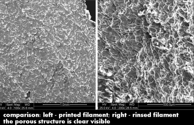
Figure 2‑14. Comparison of Porolay pre (left) and post (right) rinse. Adapted from (Krassenstein 2014)
PLA and ABS are the most commonly used materials in the 3D printing industries. Most of these 3D materials come in filamentous shapes and are available in diameters of 1.75 mm and 3 mm (MatterHackers, 2015). Problems with FDM extrusions materials include shrinkage of certain materials and warping. Methods can be employed to reduce the incidence of these phenomenon’s. This includes thermal shrinkage after deposition and can be reduced by heating the build platform or even the complete build chamber (Hofmann 2014)
2.2.5 Use of 3d printing in medicine
The use of 3D printing has seen a rapid uptake into clinical practice in many guises and specialties. It has been utilised with the fields of craniofacial and maxillofacial surgery, spinal surgery, paediatric surgery, neurosurgery, cardiothoracic surgery and radiology (Alssabbagh et al. 2017; Burdall et al. 2016; Füzesi and Gyöngy 2017). An area of medical practice that 3D printing has shown great promise is the transition of medical scan images to 3D models.
Medical images that capture 3D images include positive emission tomography (PET), 3D ultrasound, computerised tomography (CT) and Magnetic resonance imaging (MRI). MRI and CT scans are made up of layers of images; each layer is formed into a singular file in the DICOM format. These images can be stacked together to generate a slice by slice image using picture archiving and communication system (PACS). DICOM viewing software are able to convert the DICOM files using volume rendering packages into a 3D objecting. Each voxel within an CT or MRI image is called a 3D cube with an x,y and z coordinate and has a density associated to it. Volume rendering software can be used to select the density associated with the tissue density of interest, such as bone or muscle. This allows specific areas of anatomy to be modelled in 3D. This 3D image can then be exported from the DICOM viewer as an STL (STereoLithography) is a file format native to the stereolithography CAD software and is triangulated representation of a 3D model. The STL file can then be imported into a 3D printing software, where the file is again ‘sliced’ into layers that represent each of the print layers. This ‘slicing’ process is saved in a final file format called gcode, a numerical control language that the 3D printer can use to position the print head in an x, y and z axis. Finally the gcode is loaded into the printer and the 3D object will be produced. Models produced using this process have been used for the improving diagnosis, pre surgical surgical planning, simulation and patient education (Alssabbagh et al. 2017; Burdall et al. 2016; Füzesi and Gyöngy 2017).
2.3 Simulation
This section introduces the basis of simulators and their role within medical education. An overview of the currently available CICO airway trainers for the paediatric airway is presented.
2.3.1 Background
Simulation is an important component in both undergraduate and post graduate medical education and allows the recreation or imitation of key areas of medical practice for the training of medical staff (Leblanc 2012). Simulation can be utilised for orientation to new procedures, exposure to uncommon clinical scenarios, and is a valuable tool for better clinical practice, it provides a safe, controlled environment in which learning is developed and competences practiced. The role of simulation in medicine has had increased emphasis form the early 2000 where it was identified that more people died in the USA from medical mistakes than those from breast cancer and HIV combined, some 400,000 lives (Jones et al. 2015).
A recent meta-analysis of the paediatric simulation literature, demonstrated that technology-enhanced simulation had a positive effect on knowledge, time required to perform a task, behaviours and skills (Cheng et al. 2016). The term realism and fidelity are often interchanged in simulation, fidelity describes the mannequin only, whereas realism encompasses the whole simulation experience. High realism simulators have been shown to have a small to moderate benefits over low realism simulators, while for procedural simulation, like CICO physical realism, or realistic physical properties of the task trainer, is desirable to further develop kinaesthetic awareness and muscle memory (Shefrin et al. 2015). Studies have compared the use of animal models vs currently available simulators and the key difference that has been reported by user is the anatomical similarity from the animal models has been greater and thus added to the learning experience (Cho et al. 2008).
A study by Herbert (2014) addressing the role of simulation in emergency cricothyroidotomy showed that prior to simulation training only 67% of operators adhered to the derived protocols, post training and at 3, 6 and 12 months the cohort had a 100% adherence to the protocol (Hubert et al. 2014). The recommendations from Nap 4 that training in cricothyroidotomy insertion and ventilation and regular practice with such equipment should be pursued to try and minimise the rate of failure. This view is further supported by the research of Sabato (2016) that states that CICO is a “rarely practiced procedure” has helped bring an influx of CICO trainers to the market.
2.3.2 CICO Simulators
The range of simulators for CICO has grown steadily and now has a range of different styles of simulator available from self-built and even edible costing tens of pounds to high cost multi-functional simulators costing thousands of pounds are available. The simulators are evaluated on, cost, anatomical landmarks and kinaesthetic features.
2.3.2.1 Self-build CICO trainers
There are a range of homemade CICO simulators described and used for the teaching of CICO scenarios. They all share a similar, low cost, low fidelity appearance. They all utilise easily available parts found in hospitals or homes.
2.3.2.1.1 Ultimate Cricothyrotomy Trainer
Cost: Few pounds
Size: Adult only
This trainer is a simple, low fidelity model, built from easily available, often disposed of parts. It has anatomical features, including the chin, thyroid, cricoid and cricoid membrane to simulate the cricoid pop. The skin is of non-continuous construction, meaning that the aspiration technique for conformation of entry to the airway is unreliable and the kinaesthetic features of this simulator are poor. This is the most commonly used simulator in the local hospitals.
2.3.2.1.2 AmboFoam Trainer
Cost: Tens of pounds
Size: Adult only
This trainer is a simple, low fidelity model, again built from commonly available anaesthetic components. The designers have attempted to improve kinaesthetic feel by layering materials. The size of the trachea is not anatomically correct, nor is the depth from skin to cricothyroid membrane.
2.3.2.1.3 Edible trainer
Cost: few pounds
Size: Adult or child
This is the only edible simulator identified and is constructed from completely edible parts. The anatomical correlation is poor no chin or chest is used and the skin is of non-continuous construction. The kinaesthetic feel is poor, but it will form a memorable teaching aid.
2.3.2.2 Commercial CICO trainers
The range of commercial CICO trainers is vast, they can be divided into two distinct categories, those with entire head and neck assemblies and those with only the airway component.
2.3.2.2.1 Nasco Trainer
Cost: £300 +£35 replacement
Size: Adult only
This trainer has good anatomical features, although it is not a complete head it has important anatomical features and landmarks including the chin, and chest, palpable landmarks include the cricoid and thyroid cartilages. It is not a continuous skin construction and thus cannot be used for the aspiration technique to reliably identify entry to the airway.
2.3.2.2.2 SynDaver™ Cricothyrotomy Trainer
Cost: £200 + replacement parts
Size: Adult only
This trainer again has excellent anatomical features, although it is not a complete head its important anatomical features and landmarks include the chin, clavicle, hyoid bone, thyroid cartilage, cricoid cartilage, and cricoid membrane. It utilises a simplified versions of the patented SynTissue™ brand synthetic human skin, fat, muscle, and fascia tissues for good kinaesthetic features. Owing to its continuous layer construction the aspiration technique can be used reliably to confirm entry to the airway, and is the only simulator with this feature.
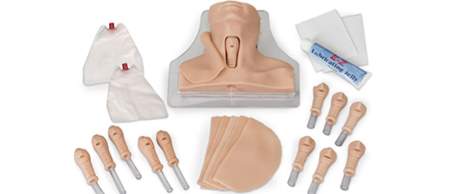
2.3.2.2.3 SimulaidsTM Cricothyrotomy Simulator
Cost: £200 + £16 replacement parts
Size: Adult & child
The simulator lacks a head and chi, although palpable landmarks include thyroid cartilage, cricoid cartilage, and cricoid membrane. It again is not a continuous construction and aspiration technique may not be reliable, it does allow identification of correct placement by inflation of simulated lung. It is available with both adult and a 3-year-old child airways, the mannequin size remains unchanged.
2.3.2.2.4 RouillyTM CICO Trainer
Cost: £779 + £30 replacement parts
Size: Adult & child (airway only)
This trainer has a improved anatomical features in terms of chin and chest compared to the simlaids cricothyroidotomy trainer. It is also avaliable with child and adult airways, but the trainer does not change in size. It is also not a continuous skin consytruction and thus the aspiration technique will be unreliable.
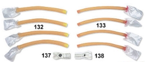
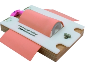
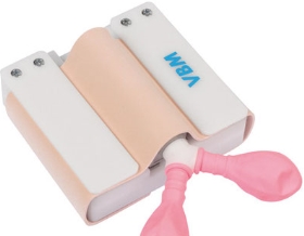
2.3.2.2.5 VBMTM CICO trainer
Cost: unavaliable
Size: Adult & child versions
The VBM CICO trainer is the only trainer identified that is available in both adult and paediatric sizes. This trainer does not offer any external anatomical features, namely chin or chest. The internal anatomical features are limited to thyroid, cricoid, and tracheal cartilages. The cricothyroid membrane is represented by only a hole, with no membrane used to simulate the pop of cricothyroid puncture. The skin and is also not of continuous construction.
The skin component of the commercial trainers are constructed from a silicone based material. Silicone has many uses and is known for flexibility and been used in the production of many simulation models (need Ref). Silicone is used as a skin simulator as a result of its excellent kinaesthetic similarities to skin. Silicone used for skin has a shore value of 10A and there are several suppliers that produce this shore value (neilsmaterial.com). This silicone is available in may formulations, as either tin cure or catalyst cure. Tin cure will set upon contact with air and catalyst cure is a two-part solution that once mixed will cure. A third component is often added to the silicone to increase it kinaesthetic feel, this is a termed a deadener. The ratio of deadener to silicone will increase its similarities to different skin and subcutaneous tissues.
3 Aims and Objectives
This current research aims to investigate the use of 3D printing as an option to produce an affordable, anatomically derived CICO trainer for the paediatric airway to facility the recommendations made by the NAP4 study that increased practice of CICO events could reduce failure rates and increase survival in the paediatric population.
Review of the available literature review has identified an area of need for a paediatric CICO trainer. The trainer will need to fulfil the following design specifications:
- Produce an infant CICO trainer
- Under the age of 1year
- Anatomically derived from radiological images
- Continuous skin construction to allow needle aspiration technique
- Feeling of cricothyroid membrane ‘pop’
- Easily reproducible on a commercially available desktop FDM printer
- Be produced using easily available filaments
- Allow the insertion of a needle cannula cricothyrotomy using the aspiration technique
- Reusable
- Evaluate the use of this model as a training tool
4 Materials and Methodology
This chapter will introduce the software packages and printer used for the design and production of the CICO training model. The software packages utilised throughout this research includes DICOM viewers for the viewing of MRI images and volume rendering of the DICOM images. Mesh modelling software for manipulation and smoothing of the mesh images. 3D CAD packages for the modelling applications, print preparation and g-code generator packages to produce the numerical control files for the printer. The FDM printer utilised for printing was the Sintron Prussa MK2 printer. The design process and print methodology will also be discussed.
4.1 Materials
This section will introduce the software packages used.
4.1.1 DICOM Viewer
The DICOM viewers utilised for this research are open source applications, freely download for the viewing of non-clinical DICOM files. Seg3D2 is a Windows based software platform with volume segmentation and processing tools developed by the NIH Centre for integrative Biomedical Computing (http://www.sci.utah.edu/cibc-software/seg3d.html). 3D Slicer is an open source, windows based software platform for medical image processing, and 3D visualization, supported by the National Institutes of Health (https://www.slicer.org). Both software packages were used for the viewing of the DICOM file series. We could view the DICOM series in coronal, sagittal, axial and volume views. Both packages allow for further manipulation of the images, the volume rendering feature were used to generate the 3D images of the infants’ torso and upper conducting airways. Following volume rendering the 3D images were exported as STL file format for further manipulation in other CAD packages.
4.1.2 Mesh modelling
For manipulation of STL (triangular meshes) files MeshLab, an open source, windows based software package was used (http://www.meshlab.net). MeshLab facilitates manipulation of STL files via a range of filtering and inbuilt rendering tools that allow editing, cleaning, healing, inspecting, rendering, smoothing, texturing and converting meshes. Post editing the files can be exported from MeshLab as an OBJ file format. The OBJ file format can be imported into many CAD software packages.
4.1.3 3D Modelling CAD
The Autodesk Fusion 360 CAD package was used for the 3D modelling (www.autodesk.com). Fusion 360 is a cloud based CAD platform that is usable across both windows and Mac platforms, accessed via a 3-year educational licence. The software package allows for manipulation of the OBJ files and further modelling of the mesh. The resulting component can be exported as a mesh file to the print platform
Autodesk Fusion 360 has an add on file package, Print Studio, this package is used to further heal and prepare the mesh file for the 3D g-code software. Print Studio repairs holes within the mesh and moved the mesh to the build plate, to prevent the printing of the object in space. The software package is also able to generate any support material that may be required for overhangs, holes or produce rafts on which the print object may sit to reduce the incidence of both warping and dehiscence from the build plate.
4.1.4 G-code generation software
Prussa Slic3r software is used to generate the g-code for the print object (http://www.prusaprinters.org). This software package allows for the final manipulation of the object prior to printing, solid parts of the object can be shelled and infilled with a material sparing matrix, such as a honeycomb pattern. The wall thickness of the object can also be specified to ensure a constant thickness throughout the whole print. Finally, Slicer generates the g-code for the printer and extruder, for example the hot end temperature, extrusion rate and bed temperature and produce the extruder head tool pathway in a numerical value protocol. The g-code file produced can be uploaded to the Sintron Prussa FDM printer for final printing.
4.2 Printer
The 3D printing of the infant CICO trainer was undertaken on a Sintron Prussa MK2 FDM printer (Figure 4‑1) with a single extruder, a build volume of 200mm x 200mm and height of 160mm and a minimum layer print height of 0.15mm. The control system is via an inbuilt LCD screen with SD card reader. The stepper motors are controlled using a RAMPS1.4 controller with the firmware loaded to RepRap Arduino board. This printer is a RepRap (Replication Rapid-Prototyper) based design and all parts of this 3D printer are Open Source and freely available (www.thigiverse.com). The kit cost of this printer is £220 excluding assembly.
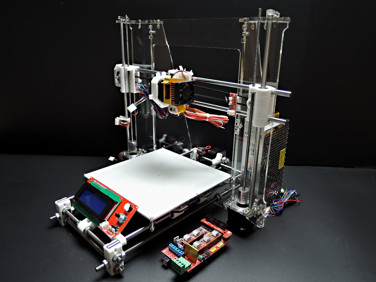
Figure 4‑1. Sintron Prussa Mk2 FDM printer
4.3 Methodology
The basis for the CICO trainer is an MRI scan series of a child under 1 year of age. The MRI scans were obtained from Great Ormand Street Hospital (GOSH). The scan subject, a post mortem, 3-month-old, 10kg male child. The images were acquired using ethical approval granted to Dr M Jones under his current research grant. The DICOM files were supplied in an anonymised, compressed DICOM image format, containing 160 individual DICOM files. The scan subject was scanned using a Siemens 1.5 Teslar MR scanner, 160 cross sections were provided with a resolution of 4mm. The images were captured in a T2 weighting, and includes the head, neck and partial thorax to the 7th thoracic vertebra. The airway is seen from the nose and mouth until above the carina, the point of division of the trachea to left and right main bronchi.
The MRI images were used to produce a torso model that had the desirable attributes of the CICO trainers reviewed previously. These features included a chin, chest and built to the appropriate size of an infant. The airway component was to be anatomically correct, within the limitations placed on us by the MRP images. The important features to include were the
4.3.1.1 Torso model
Seg3D2 was used for the surface volume rendering of the infant trainer. The DICOM was loaded and the threshold tool used. The threshold tool enables all voxels within an intensity range to be selected and viewed. The MRI image were captured in a T2 weighted study, water will appear bright white and air will be black. The intensity value of air will be 0 while water will have a value close to the maximum intensity of 601 of this scan. Using the sample tool to select the highest intensity of the air in this scan a lower threshold of 54.09 was used and the volume rendering of the child’s skin generated as shown in Figure 4‑2(McRobbie 2003). The torso file was saved and exported as an STL file.
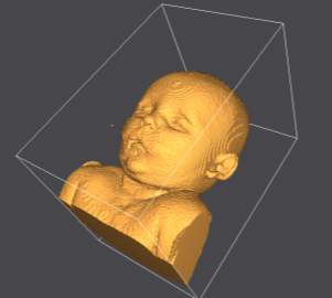
Figure 4‑2. Volume rendering of infant.
The torso STL file was exported to MeshLab for smoothing and removal of any redundant voxels, outside of the skin surface form the volume rendering process. The smoothing tool within MeshLab was used to eliminate the steps that occur between the 4mm thick sections, as evident in Figure 4‑2. Laplacian smoothing was employed to smooth the volume rendering, the Laplacian smoothing algorithm moves each vertex to the average of its adjacent vertices, thus the size and shape is unaltered Figure 4‑3.
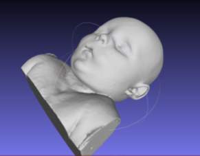
Figure 4‑3. Post Laplacian smoothing and voxel removal in MeshLab.
The smoothed STl file was imported into Fusion 360 for further manipulation. The original MRI image was of the child with the head in a flexed position (chin on chest) and not the position required for CICO training. The head was extended using the mesh editing facility to open the anterior neck surface. The head was extended at the level of the base of skull, the position of normal anatomical flexion/extension of the head. The resultant void in the neck was filled using the patch and loft tools. The area of anterior neck overlying the hyoid, thyroid cartilage, cricoid thyroid and cephalad trachea was removed and a tray inserted to allow replacement of the airway simulation and overlying skin. The torso model was trimmed to reduce the printing requirements, the skull vortex was removed in the axial plane to the level of the nose and from the clavicle down. The posterior surface of the torso was removed to the level of the tragus of the ears. (Figure 4‑4).
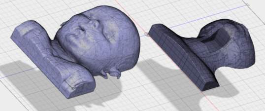
A
B
Figure 4‑4. (A) Child pre-production (B) Post head extension, airway chamber cut and slimmed for printing.
The completed torso model was converted to a continuous mesh file, exported to Print Studio for final mesh repair and preparation for printing. The model was aligned with the print bed and the software algorithm recommended no supports were required. The file was exported as an OBJ file to the Slic3r software. The following parameters, shown in Table 2‑1were used for the print of the torso file on the Sintron Prussa Mk2 printer.
| Printer | ||
| Print material | PLA | |
| Extruder temp | 240 | Co |
| Bed temperature | 60 | Co |
| Layer height | 0.2 | mm |
| Solid infill | ||
| structure | Honeycomb | |
| infill percentage | 5 | % |
| Wall thickness | 1 | mm |
Table 4‑1. Print settings for torso model print
4.3.1.2 Airway simulation module
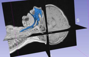
For production of the airway simulation module an anatomically directed model of the airway was required. To archive this the MRI images were again utilised, volume renderings of the conducting airways were generated using the second DICOM viewer, 3D slicer. The second DICOM viewer, 3D slicer has several specialist modules that enable the creation of specific volume renderings, specifically an airway volume rendering module. The airway rendering module was used to create a volume rendering of the airway from the nasopharynx and oropharynx to just above the carina. This module requires the use of reference voxels at the beginning and end of the trachea. These voxels are used to determine the intensity value of the voxels representing air within the trachea, the software then employs a nomogram to set the intensity range to isolate the airways for the MRI scan. The software highlights all voxels within the airways from the nose/mouth to the carina in a blue layer (Figure 4‑5).
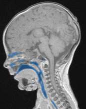
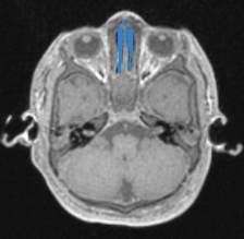
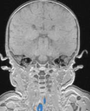
Figure 4‑5. Sagittal (A), axial (B) and coronal (C) views of the infant airway.
The airway volume rendering tool further apply the intensity value to each DICOM file making up the DICOM series of the MRI scan to generate the volume rendering of the airway Figure 4‑6.
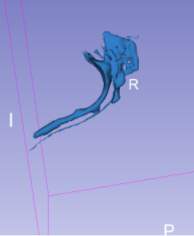
A
B
Figure 4‑6. (A) Airway volume rendering (B) airway volume rendering with MRI overlay
The completed airway volume rendering of the conducting airway was exported to MeshLab as an STL file for further manipulation. Within MeshLab the redundant voxels were removed using the edit feature. Smoothing of the airway volume rendering was completed using the Laplacian smoothing algorithm, this removed the steps caused by the 4mm wide segments from the MRI images.
Following the MeshLab manipulation, the smoothed airway volume rendering was exported as an STL file to fusion 360 for modelling of the anatomical structures. The mesh was imported and the sagittal MRI section was loaded as a canvas to enable the key anatomical features to be modelled. The hyoid bone, thyroid cartilage, cricoid cartilage and the cephalad trachea were modelled using the fusion 360 modelling tools (Figure 4‑7). The outline of the anatomical structures that could be identified from the MRI images were constructed infusion 360. The important feature of each of the anatomical components were transcribed into the model.


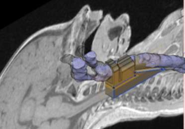
Hyoid Bone
Thyroid cartilage
Cricoid cartilage
Trachea
Figure 4‑7. Airway module with MRI as canvas and airway volume rendering in Fusion 360
The airway model was angulated to accommodate the extension applied to the head of the torso model and tracheal rings added Figure 4‑8.


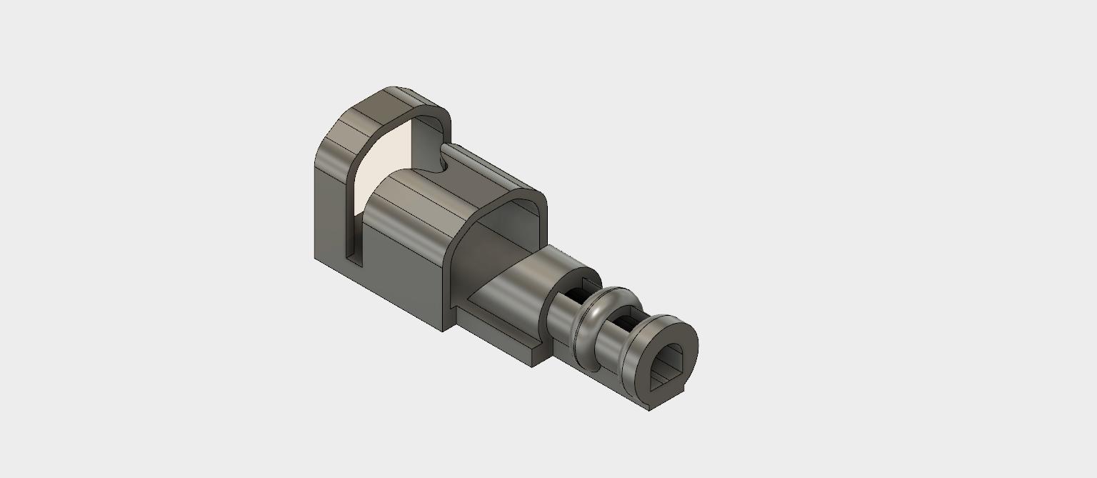
Hyoid Bone
Thyroid cartilage
Cricoid cartilage
Trachea
Trachea rings
Figure 4‑8. Airway module
The airway module will be printed in a range of materials ABS, PLA, Fillaflex 98A and Gel-lay. Each of the prints will be evaluated for the following features
- Smoothness – does the internal print area appear smooth and will not interfere with the advancement of a cannula
- Anatomical features – Are the following features clearly identifiable
Hyoid bone, Thyroid and cricoid cartilages and tracheal rings
- Compressibility – does the print appear to be compressible, representing the collapsible nature of the airway in the child.
- Print quality – holes in print material, bridging, warping
4.3.1.3 Cricothyroid membrane
The cricothyroid membrane has a feeling of a pop as a needle is passed through and will be recreated using a thin plastic membrane. For the cricothyroid membrane, a thermos set plastic sleeve will be used to wrap around the airway module prior to the production of the continuous skin layer.
4.3.1.4 Continuous skin construction
Simulation skin can be produced using Platsil Gel 10 a two-part platinum catalyst cured silicone with a shore hardness of A10 (Neils Materials, UK). The skin construction will be built based on the instructions from Polytek (2017) datasheet. The silicone is mixed in a 1:1 ratio of parts A and B. This mix ration will produce a clear silicone with a shore hardness of A10. The shore hardness can be further reduced with the addition of a silicone deadener. The deadener used is Platsil Deadener LV, this can be added in ratios of 50% to 200% of the total A+B volume (Neils Materials, UK). The colour of the silicone can be changed by the addition of a silicone pigment (Neils Materials, UK).
Following mixing of the silicone in the ratios as described, the silicone will be poured into a mould produced from the torso file. The mould will allow for the airway module to be et within a continuous skin matrix and fit within the area of anterior neck removed during the torso model development. The mould will be printed of the FDM printer using PLA filament. The silicone will be mixed as described above and mixed with 4 ratios of 0%, 50%, 100% and 150% deadener. The silicone will be injected into the moulds coated in a release agent of paraffin wax and thinners, the airway module will be contained within. The silicone will be left to set for 30 minutes and removed from the mould. Each of the 4 deadener ratios will be evaluated for the following:
- Tackiness
- Ability to palpate cricoid cartilage
- Ability to pass cannula
- Resilience to repeated cannulation
4.3.2 Model testing
The testing of the infant CICO trainer will be carried out as part of an airway training day for anaesthetic trainees. The infant CICO trainer model will be used as part of the teaching session, the evaluators will be anaesthetic trainees who have completed their training in paediatric anaesthesia and have a substantive level of paediatric anaesthetic experience. Verbal consent was received from all evaluators.
Each evaluator will be introduced to both the ultimate CICO trainer and the infant CICO trainer developed as part of this research. The testers will be asked to practice a CICO scenario on each of the training models. The CICO method used will be the same for both simulators and as described in section 2.1.7. They will each practice on the Ultimate Trainer first and then practice on the infant CICO trainer after. The two trainers will be used by all the evaluators to allow comparison. The evaluators will be asked to complete an evaluation of each trainer using the form shown in (appendix 2). The following areas of data will be captured:
- Ability to identify the following anatomical features
- Hyoid bone
- Thyroid cartilage
- Cricoid cartilage
- Cricothyroid membrane space
- Tracheal rings
- Feeling of ‘pop’ as needle passes through Cricothyroid membrane
- Able to use aspiration technique
- Overall kinaesthetic feeling: comparison to cannulation of a child
- Overall perception of each of the two trainers.
4.3.3 Cost calculation
The cost of inhouse production of the infant CICO trainer will be derived from the raw material cost and a percentage per unit time of the initial printer cost. The weight of filament used is calculated by the 3D print software. The cost of the print items will also be sourced from a commercial print provider via the cost estimation page of 3DHubs.com.
5 Results
5.1 Torso model
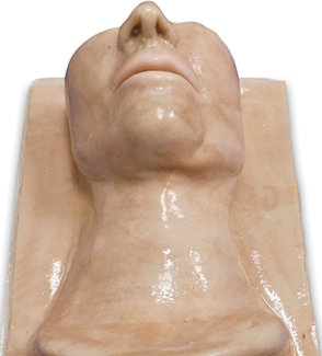
The print of the infant torso was evaluated for the ability to identify the following anatomical features, as specified in the design specification. The chin, chest, clavicles and anterior neck were all identified with the head in an extended position. The torso print in white PLA filament is shown in Figure 5‑1.
Clavicles Chin
Chest Airway module Mouth
tray cut-out


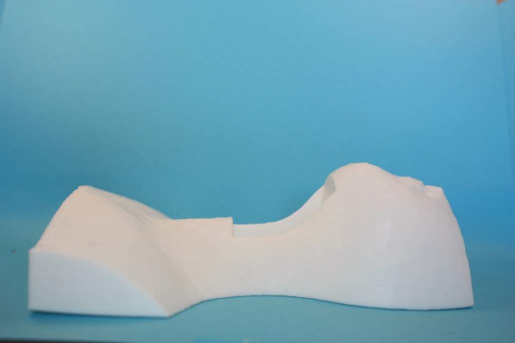
Figure 5‑1.Lateral view of infant CICO trainer torso.
5.2 Airway Module
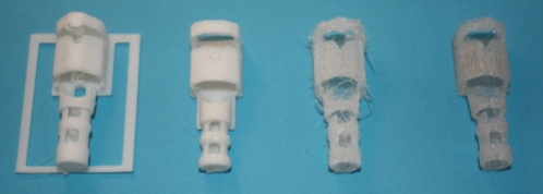
The airway modules were printed in the following materials ABS, PLA, Fillaflex 98A and Gel-Lay are shown in Figure 5‑2.
B
A
C
D
(A) ABS (B) PLA (C) Fillaflex (D) Gel-Lay
Figure 5‑2. Airway module prints
Following this the four materials were evaluated for print quality, bridging, smoothness and compressibility. The results and print settings for each of the materials in shown in Table 5‑1.
| Printer | |||||
| Print material | PLA | ABS | Fillaflex | Gel-lay | |
| Extruder temp | 240 | 260 | 220 | 215 | Co |
| Bed temperature | 60 | 100 | 40 | 40 | Co |
| Layer height | 0.2 | 0.2 | 0.2 | 0.2 | mm |
| Assessment | |||||
| Smoothness | 5 | 4 | 2 | 4 | |
| print quality | 5 | 5 | 1 | 5 | |
| compressibility | 1 | 1 | 5 | 4 | |
| Anatomical features | 5 | 5 | 3 | 4 | |
| Overall Score % | 80 | 75 | 50 | 85 | % |
Table 5‑1. Print settings for airway module.
Each of the four areas that were assessed using a 5-point scale 5 = excellent and 3 = Average and 1 = Poor.
The Gel-lay was the best overall performing filament used producing a good level of detail in the anatomical features, no bridging and a smooth finish. After post production finishing by water submersion for three days to remove the PVA component of the filament the compressibility of the airway module was good. The Fillaflex 98A was the lowest overall performer of the four materials, all the anatomical components were identifiable but a poor overall print quality was evident. The poor overall quality was attributable to the high degree of bridging, holes in the print surface and smoothness. The holes seen in the print surface where most evident in the overhangs of the hyoid bone and the upper surface of the trachea. The ABS and PLA both produced excellent print qualities in terms of anatomical features, smoothness and bridging. Both materials lacked any compressibility, reducing their overall rating.
5.3 Continuous skin layer
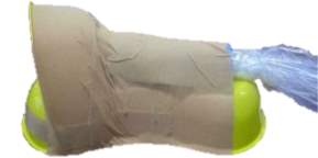
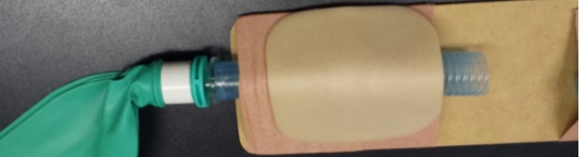
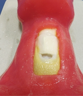
The skin layer was produced in 4 shore harnesses using the 4 mix ratios of deadener LV to the standard mix of silicone of 0%, 50%, 100% and 150%. The finished modules are shown in Figure 5‑3. The results of the evaluation are summarised in Table 5‑2.
| Deadener (%) | 0 | 50 | 100 | 150 |
| Tackiness | nil | slight | slight | very |
| Ability to palpate cricoid cartilage | unable | very firm palpation | firm palpation | light palpation |
| Ability to pass cannula | easy | easy | slight resistance | dragging feeling |
| Resilience to repeated cannulation | excellent | excellent | good | poor |
Table 5‑2 continuous skin moulding evaluation.
The increasing ratio of deadener to silicone resulted in an increasing feeling of tackiness to the silicone. The silicone became softer as more deadener was added and the ability to feel the cricoid cartilage became progressively easier. The passage of the cannula became more difficult as the ration of deadener increased. The silicone became more prone to damage with increasing deadener.
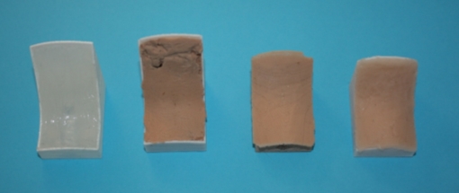
B
A
C
D
(A) 0% (B) 50% (C) 100% (D) 150%
Figure 5‑3. Completed airway module and continuous skin mould with increasing percentage of deadener LV.
5.4 Infant CICO trainer evaluation
In total, eight evaluators were recruited for the evaluation process by informal invitation to colleagues at the local hospital. Evaluators were of mixed gender, 3 females, 5 males and graded ST3 or greater. All evaluators had received training in paediatric anaesthesia and had attended a training session in the use of the CICO protocol.
5.4.1 Evaluation of palpation of anatomical features
The results for the palpation of the anatomical features s for the Ultimate Trainer and the infant CICO trainer are shown in graphs 1 and 2 respectively. The hyoid bone was not palpable on the Ultimate Trainer, while on the infant CICO trainer the hyoid bone was detectable but rated as able to palpate, but unable to confidently identify structure to felt and identifiable with light palpation. The thyroid and cricoid cartilages were felt in both trainers. It was observed that both the thyroid and cricoid cartilages were harder to feel in the infant CICO trainer with 87.5% of evaluators using firm palpation vs 25% in the Ultimate Trainer. The tracheal rings showed similarities through both groups, in the infant CICO trainer one evaluator felt the rings using light palpation. The palpation of the cricothyroid membrane was felt with light palpation by 87.5% and firm palpation by the remaining 12.5% of evaluators using the Ultimate Trainer. In the infant CICO trainer firm palpation was required by all the evaluators.
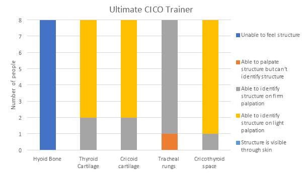
Graph 1. Identification of anatomical features in the Ultimate Trainer by palpation
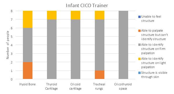
Graph 2. Identification of anatomical features in the infant CICO trainer by palpation
5.4.2 Evaluation of kinaesthetic properties
The findings from the kinaesthetic properties of the two trainers is shown in graph 3. In the Ultimate Trainer 12.5% of evaluators felt a distinguishable ‘pop’ as the needle passed through the cricothyroid membrane and entered the airway lumen. In the infant CICO trainer all evaluators felt a ‘pop’ as the needle entered the lumen. The aspiration technique could be employed only in the infant CICO trainer, it could not be used in the Ultimate Trainer. The feeling of advancing the cannula through the skin of the two trainers was felt to be more representative of the real feeling in the infant trainer by all evaluators as opposed to the Ultimate Trainer with only 12.5% of evaluators describing it as similar.
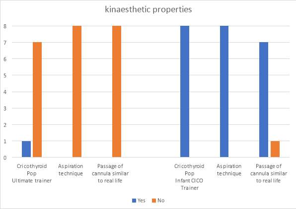
Graph 3. The kinaesthetic properties of the two trainers
5.4.3 Overall satisfaction with the infant CICO trainer
The overall satisfaction for the Ultimate Trainer is shown in graph 4. The satisfaction for the Ultimate Trainer was rated as poor or average. The infant CICO trainer was rated as good by 75% of evaluators and the remaining as excellent.
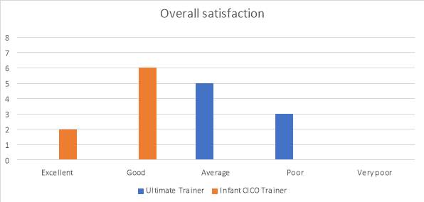
Graph 4. Overall satisfaction of the two trainers
5.4.4 Cost
The cost of the components used to produce the infant CICO trainer are shown in Table 5‑3. The cost is based on the following unit costs:
PLA: £20 / KG
Lay-Gel: £120 / KG
Silicone and deadener: £10 / 100ml
| In house print | 3D Hub | |||
| Component | Filamnet | Amount of filament (KG) | Cost | Cost |
| Torso | PLA | 0.143 | £ 2.86 | £ 37.00 |
| Tray | PLA | 0.004 | £ 0.08 | |
| Airway | Lay-Gel | 0.002 | £ 2.24 | £ 4.80 |
| silicone (mls) | ||||
| Skin | A10 | 22 | £ 2.20 | £ 2.20 |
| Total | £ 5.38 | £ 44.00 | ||
Table 5‑3. Cost of component production inhouse and commercial printer services
6 Discussion
6.1 Torso model
A torso model was designed to function as a platform to support airway modules, whilst providing the surface anatomical features required of a trainer. The torso, having been generated from the DICOM image series and through a process of image manipulation displayed the key surface features required. The torso model required several steps following the volume rendering process to create a usable model. These steps were a result of the following factors; firstly, the DICOM image resolution and secondly, the scan subject being imaged with the head in a flexed position. The image resolution provided was in 4mm sections, although this did not pose a significant issue for the torso model several smoothing algorithms were required to produce a smooth usable model. The second issue of the imaged child being in the flexed position posed more of a significant issue. The extension of the infants’ head could not be performed within the DICOM image software and thus, had to be undertaken post volume rendering. Although this did not unduly affect the surface landmarks, the positioning of the underlying structures relative to the surface landmarks were affected.
The torso model printed on the FDM printer, with a white 1.75mm PLA filament, a good surface finish was achived, appropriate for the intended use with a print height of 0.2mm. The torso infill of 5% may have been too low for the use intended. The torso model withstood the use during the evaluation of the model. However, the torso model did display signs of wear and tear around the area supporting the removable airway module. Therefore, a higher infill ratio of greater than 5% should be considered for further productions.
A further modification during the evaluation process was required owing to one of the cannulas being longer than expected and projecting beyond the end of the airway module. This necessitated an additional hole being made into the torso to accommodate the longer cannula.
6.2 The airway module
The design of the airway module utilised the volume rendering model from the DICOM viewer, however, the volume rendering function could not be used to its full potential. The use of the volume rendering was limited by the low resolution of the DICOM image series. The MRI scans were supplied in a compressed file format and each voxel represented over 1mm3, as a result the meaningful anatomical structures could not be identified clearly. Modelling of the anatomical structures, including the hyoid, thyroid, cricoid and tracheal rings could not be selected using the volume rendering functions contained with the 3D slicer. The volume rendering could only be used to produce a volume rendering of the inside of the airways.
The evaluation of the four print materials of the airway module in ABS, PLA, Fillaflex and Gel-Lay resulted in the ABS, PLA and Fillaflex being deemed inadequate prior to production of the evaluation model. The ABS and PLA were excluded from the evaluation model because of their poor flexibility, despite the excellent print quality. The Fillaflex 98A had the best compressibility and the nearest Shore value to that of infantile cartilage of any of the materials evaluated. It was excluded from the evaluation model because of the poor print quality, smoothness and ability to identify the anatomical landmarks. The limitations with the Fillaflex is most likely contributed by the extruder design used on the Sintron Prussa MK2 printer. The flexible filament are difficult to control in printers of this design. The Gel-Lay displayed the best overall score, its compressibility was slight less than the Fillaflex, but there was still a god amount observed. The print quality was excellent and it did not display any bridging because of the print filament being stiff at the point of printing and the final print only becoming flexible after submersion in water for 3 days.
6.3 Continuous skin layer
The continuous skin layer presented several challenges through the development of the model. The greatest challenge to the production of this layer was the use of the 3D printer. Currently the printing of silicone on a FDM printer is not possible. The printing of silicone in 3D printing has received a lot of interest in recent years. In the home printing market 3D printing of silicone has been limited to the extrusion of liquid silicone from a nozzle onto the build surface of a single part tin cure silicone. Recent development by commercial printers offers the opportunity to print silicones. The USA based company Lazarus, specialist in the printing of medical simulation models have developed an ability to print silicone using an adapted Ultimaker FDM machine using a process of silicon-based extrusion (Sher 2015). The printing technique is awaiting a patent application and remains undisclosed at present. The printer is able to produce different densities of silicone, in different colours within the same object coupled with models that are also able to bleed on cutting (Sher 2015).
The decision to use a moulding process was made, since the mould could be created using the 3D print technology and the moulding could be easily carried out. The use of a two-part silicone with an initial shore hardness of A10 was chosen, based on the other simulation models and its use in the special effects industry for the recreation of skin. The use of a deadener was introduced to the silicone to increase further the feeling of real skin. The use of deadener is a trade-off between two properties of the silicone, firstly the silicone remains tacky to touch and secondly, the structural integrity was reduced as shown by the result in Table 5‑2. The feeling of tacky to touch could be overcome with the use of a talcum powder for the 100% and 150% ratio of deadener. The silicone remained tacky inside, such that as the cannula was passed through the skin, more resistance was felt. In the 100% ratio of deadener the increased resistance did not affect the feel of the model from that of a real cannulation, however, the 150% deadener ratio the resistance was such that the feeling of cannulation was very unrealistic. The resilience to repeated puncture was also significantly reduced with the 150% deadener. Such that after 3 cannulations the silicone began to break up and the module was no longer usable. The 100% deadener ratio was chosen to be used in the evaluation model.
6.4 Infant CICO trainer evaluation
The evaluation of the infant CICO trainer was paired against the currently used CICO trainer the Ultimate Trainer. The power of the evaluation group was low, but demonstrated some important points. The palpation of the anatomical features appeared more difficult in the infant CICO trainer than compared with the Ultimate Trainer with 87.5% vs 25% using firm palpation. This is in accordance with the desired outcome, the airway landmarks in an infant are much harder to feel than those in an adult. The ultimate CICO trainer is designed to simulate the adult airway, thus the infant CICO trainer is more representative of the infant airway in relation to palpation. The same result was observed for the palpation of the cricothyroid membrane. It could be suggested that as the airway cartilages and tracheal rings are printed in softer materials the pressure need to palpate will increase, improving the realisms of the simulator. For this procedure, the trade-off between palpation pressure and collapsing the airway should be balanced. Something this simulator currently does not simulate well, owing to the stiffness of the cartilages.
The results from the kinaesthetic property investigations of the infant CICO trainer showed a significant improvement between it and the Ultimate Trainer. The ‘pop’ of passing through the cricothyroid membrane was felt by all evaluators in the infant CICO trainer, while only one evaluator felt it in the Ultimate Trainer. The feeling of the ‘pop’ is an important component of knowing you have entered the airway lumen. The ability to use the aspiration technique in the infant CICO trainer was shown by all evaluators. The ‘pop’, coupled with the aspiration of air is the key feature to signal the need to stop advancing the needle and off load the cannula into the airway lumen. The ability to use the aspiration technique was reported by no evaluators in the Ultimate Trainer. The findings of the evaluation of the continuous skin component of the passage of the cannula feeling like that of a real child was further supported by the evaluators in the infant CIOC trainer where 87.5% of evaluators felt it was like cannulating a child.
6.5 Cost evaluation
The cost of inhouse production of the infant CICO trainer of in house production for material cost was £5.38. This excluded the cost of the printer which equates to a one-off cost of £200 (ebay.co.uk). The cost of the in-house production of a CICO trainer, compared to the cost of the already available CICO trainers (section 2.3.2.2 Commercial CICO trainers) is significantly lower. The cost of the infant CICO trainer, when produced in-house is lower than the cost of the consumable components of the Nasco Trainer, SimulaidsTM Cricothyrotomy Simulator and RouillyTM CICO Trainer. The commercial printer option, while significant more expensive than the in-house option at £44.00 would enable organisations to trial this simulator. The per unit cost was significantly lower if multiple items were ordered.
7 Further Work
A further detailed analysis of the tissues that form the paediatric airway is required as limited data is currently available in the literature pertaining to the tissue characteristics. This work would look to address the dynamic characteristics of the tissues forming the airway, namely the thyroid, cricoid and tracheal ring cartilages. Following this, further analysis is required of the materials available for FDM printers to try and better match the tissue characteristics with that of the materials, therefore, further enhancing the simulation.
The use of higher resolution DICOM files would allow the DICOM volume rendering software to be fully utilised for the volume rendering of not only the conducting airways but also the structures that form the airway. These structures include the bones, tissues, cartilages and blood vessels. The use of this technology would allow for even greater anatomical correlation and the ability to model airway pathologies, for example airway tumours. The use of this would be instrumental in the management of neonates born with suspected airway problems, allowing the clinical team to rehearse the airway management prior to delivery.
Further evaluation of the role of simulation in the management of the difficult paediatric airway would be of great benefit to further endorse the role of simulation, to help improve the outcomes of CICO scenarios. This work could look at the management of the difficult airway pre-simulation and post-simulation based training in CICO management in the paediatric airway.
Further work addressing the role of the new developing print technologies in medical simulation. The evolving technology of multi-jet printing could play a significant place for printing of patient specific airway simulators, presenting an exciting opportunity for patient specific simulation.
8 Conclusion
The aim of this research was to investigate the possibility of utilising the modality of 3D printing to develop an affordable, anatomically derived CICO trainer for the paediatric airway. The design brief detailed the following specifications:
- Produce an infant CICO trainer
- Under the age of 1year
- Anatomically derived from radiological images
- Continuous skin construction to allow needle aspiration technique
- Feeling of cricothyroid membrane ‘pop’
- Easily reproducible on a commercially available desktop FDM printer
- Be produced using easily available filaments
- Allow the insertion of a needle cannula cricothyrotomy using the aspiration technique
- Reusable
This present research has enabled the development of a simple CICO trainer for the infant paediatric patient fulfilling the criteria established in the design brief. The infant CICO trainer has been shown to be superior in many areas of the CICO scenario training, the aspiration technique can be used with this trainer, a more definitive ‘pop’ is felt on entry to the airway and anatomically representative of an infant. The use of the infant CICO trainer in the training of CICO scenarios for anaesthetists has been demonstrated and shown to be superior to other trainers. The production cost using a commercially available desktop FDM printer is significantly less than that of the commercially available CICO trainers. In conclusion a simple, affordable and reusable infant CICO trainer has been developed that can be used for the training of medical staff in a potentially lifesaving procedure.
9 Appendix
9.1 Appendix 1
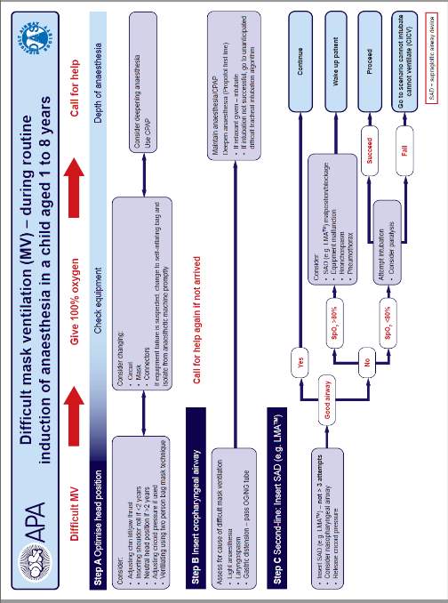
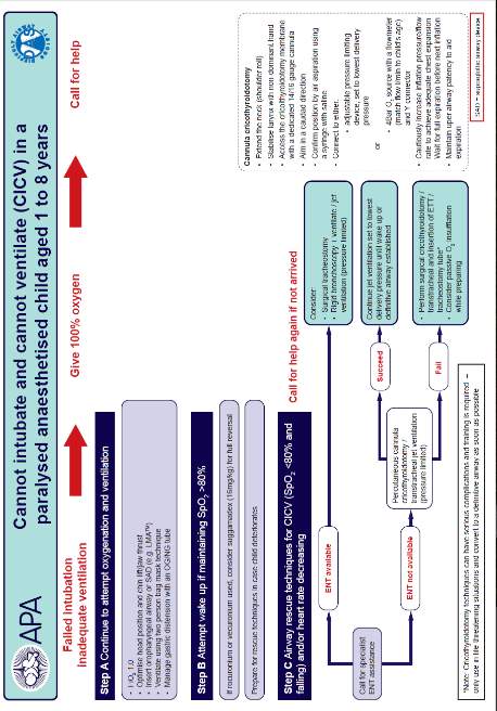
9.2 Appendix 2
10 References
Alssabbagh, M., Tajuddin, A.A., Manap, M.A. and Zainon, R. (2017). Evaluation of 3D printing materials for fabrication of a novel multi-functional 3D thyroid phantom for medical dosimetry and image quality. Radiation Physics and Chemistry [Online]. Available at: http://linkinghub.elsevier.com/retrieve/pii/S0969806X1630370X [Accessed: 20 January 2017].
Apfelbaum, J.L., Hagberg, C.A., Caplan, R.A., Blitt, C.D., Connis, R.T., Nickinovich, D.G., Hagberg, C.A., et al. (2013). Practice guidelines for management of the difficult airway: an updated report by the American Society of Anesthesiologists Task Force on Management of the Difficult Airway. Anesthesiology [Online] 118:251–70. Available at: http://anesthesiology.pubs.asahq.org/Article.aspx?doi=10.1097/ALN.0b013e31827773b2 [Accessed: 1 April 2017].
APLS (2011). Advanced Paediatric Life Support: Fifth Edition. Samuels, M. and Wieteska, S. (eds.). The Atrium, Southern Gate, Chichester, West Sussex, PO19 8SQ, UK: John Wiley & Sons, Ltd. Available at: http://doi.wiley.com/10.1002/9781118369784 [Accessed: 1 April 2017].
Bill, J.S., Reuther, J.F., Dittmann, W., Kübler, N., Meier, J.L., Pistner, H. and Wittenberg, G. (1995). Stereolithography in oral and maxillofacial operation planning. International Journal of Oral and Maxillofacial Surgery [Online] 24:98–103. Available at: http://linkinghub.elsevier.com/retrieve/pii/S0901502705808690 [Accessed: 19 March 2017].
Black, A., Flynn, P., Popat, M., Smith, H., Thomas, M. and Wilkinson, K. (2015). Paediatric Difficult Airway Guidelines [Online]. Available at: https://www.das.uk.com/guidelines/paediatric-difficult-airway-guidelines [Accessed: 1 April 2017].
Bowyer, A. (2014). 3D Printing and Humanity ’ s First Imperfect Replicator. 3D Printing [Online] 1:2013–2014. Available at: http://online.liebertpub.com/doi/10.1089/3dp.2013.0003 [Accessed: 20 March 2017].
Burdall, O.C., Makin, E., Davenport, M. and Ade-Ajayi, N. (2016). 3D printing to simulate laparoscopic choledochal surgery. Journal of pediatric surgery [Online] 51:828–31. Available at: http://www.sciencedirect.com/science/article/pii/S0022346816002098 [Accessed: 14 November 2016].
Carlsson, B. (1984). The development and use of machine tools in historical perspective. Journal of Economic Behavior & Organization [Online] 5:91–114. Available at: http://linkinghub.elsevier.com/retrieve/pii/0167268184900283 [Accessed: 1 April 2017].
Cheng, G.Z., Estepar, R.S.J., Folch, E., Onieva, J., Gangadharan, S. and Majid, A. (2016). Three-dimensional printing and 3D slicer powerful tools in understanding and treating structural lung disease. Chest [Online] 149:1136–1142. Available at: http://linkinghub.elsevier.com/retrieve/pii/S0012369216416132 [Accessed: 19 March 2017].
Cho, J., Kang, G.H., Kim, E.C., Oh, Y.M., Choi, H.J., Im, T.H., Yang, J.H., et al. (2008). Comparison of manikin versus porcine models in cricothyrotomy procedure training. Emergency medicine journal : EMJ [Online] 25:732–4. Available at: http://emj.bmj.com/cgi/doi/10.1136/emj.2008.059014 [Accessed: 2 April 2017].
CORMACK, R.S. and LEHANE, J. (1984). Difficult tracheal intubation in obstetrics. Anaesthesia [Online] 39:1105–1111. Available at: http://www.ncbi.nlm.nih.gov/pubmed/6507827 [Accessed: 23 March 2017].
Fahad, M., Dickens, P. and Gilbert, M. (2013). Novel polymeric support materials for jetting based additive manufacturing processes. Rapid Prototyping Journal [Online] 19:230–239. Available at: http://www.emeraldinsight.com/doi/10.1108/13552541311323245 [Accessed: 23 January 2017].
Fiadjoe, J.E., Nishisaki, A., Jagannathan, N., Hunyady, A.I., Greenberg, R.S., Reynolds, P.I., Matuszczak, M.E., et al. (2016). Airway management complications in children with difficult tracheal intubation from the Pediatric Difficult Intubation (PeDI) registry: a prospective cohort analysis. The Lancet Respiratory Medicine [Online] 4:37–48. Available at: http://linkinghub.elsevier.com/retrieve/pii/S2213260015005081 [Accessed: 18 March 2017].
Fillaments.ca (2014). Shore Hardness of Flexible 3D Printing Materials – Filaments.ca [Online]. Available at: https://filaments.ca/blogs/3d-printing/15475957-shore-hardness-of-flexible-3d-printing-materials [Accessed: 22 January 2017].
Frei, F.J. and Ummenhofer, W. (1996). Difficult intubation in paediatrics. Pediatric Anesthesia [Online] 6:251–263. Available at: http://doi.wiley.com/10.1111/j.1460-9592.1996.tb00447.x [Accessed: 19 February 2017].
FunToDo (2017). About Our 3D Dlp Resins [Online]. Available at: http://www.funtodo.net/our-3d-resin-blends.html [Accessed: 23 January 2017].
Füzesi, K. and Gyöngy, M. (2017). Comparison of Two Inexpensive Rapid Prototyping Methods for Manufacturing Filament Target Ultrasound Phantoms. Ultrasound in Medicine & Biology [Online] 43:712–720. Available at: http://linkinghub.elsevier.com/retrieve/pii/S0301562916304033 [Accessed: 23 March 2017].
Gibson, I., Rosen, D. and Stucker, B. (2010). Additive Manufacturing Technologies: Rapid Prototyping to Direct Digital Manufacturing. [Online]:1–459. Available at: https://www.amazon.co.uk/Additive-Manufacturing-Technologies-Prototyping-Digital/dp/1441911197 [Accessed: 23 March 2017].
Gu, P., Zhang, X., Zeng, Y. and Ferguson, B. (2001). Quality analysis and optimization of Solid Ground Curing process. Journal of Manufacturing Systems [Online] 20:250–263. Available at: http://linkinghub.elsevier.com/retrieve/pii/S0278612501800455 [Accessed: 19 March 2017].
Hall, G.M. (2010). Anaesthesia and Intensive Care A-Z: An Encyclopaedia of Principles and Practice, 4th ed. Anesthesia & Analgesia [Online] 110. Available at: http://journals.lww.com/anesthesia-analgesia/Fulltext/2010/03000/Anaesthesia_and_Intensive_Care_A_Z__An.71.aspx [Accessed: 23 January 2017].
Harless, J., Ramaiah, R. and Bhananker, S.M. (2014). Pediatric airway management. International journal of critical illness and injury science [Online] 4:65–70. Available at: http://www.ncbi.nlm.nih.gov/pubmed/24741500 [Accessed: 19 February 2017].
Heinrich, S., Birkholz, T., Ihmsen, H., Irouschek, A., Ackermann, A. and Schmidt, J. (2012). Incidence and predictors of difficult laryngoscopy in 11.219 pediatric anesthesia procedures. Paediatric Anaesthesia [Online] 22:729–736. Available at: http://www.ncbi.nlm.nih.gov/pubmed/22340664 [Accessed: 19 February 2017].
Hofmann, M. (2014). 3D printing gets a boost and opportunities with polymer materials. ACS Macro Letters [Online] 3:382–386. Available at: http://pubs.acs.org/doi/abs/10.1021/mz4006556 [Accessed: 23 March 2017].
Hubert, V., Duwat, A., Deransy, R., Mahjoub, Y. and Dupont, H. (2014). Effect of Simulation Training on Compliance with Difficult Airway Management Algorithms, Technical Ability, and Skills Retention for Emergency Cricothyrotomy. Anesthesiology [Online] 120:999–1008. Available at: http://www.ncbi.nlm.nih.gov/pubmed/24434303 [Accessed: 2 April 2017].
Jagannathan, N., Sohn, L. and Fiadjoe, J.E. (2016). Paediatric difficult airway management: what every anaesthetist should know! British journal of anaesthesia [Online] 117 Suppl:i3–i5. Available at: http://bja.oxfordjournals.org/content/early/2016/04/19/bja.aew054.extract# [Accessed: 4 December 2016].
James, W.J., Slabbekoorn, M.A., Edgin, W.A. and Hardin, C.K. (1998). Correction of congenital malar hypoplasia using stereolithography for presurgical planning. Journal of Oral and Maxillofacial Surgery [Online] 56:512–517. Available at: http://linkinghub.elsevier.com/retrieve/pii/S0278239198907261 [Accessed: 19 March 2017].
Jennings, A. (2017). Troubleshooting Guide to 16 Common 3D Printing Problems _ All3DP. All3dp [Online]. Available at: https://all3dp.com/common-3d-printing-problems-3d-printer-troubleshooting-guide/ [Accessed: 5 March 2017].
Jones, F., Passos-neto, Carlos EduardoJones, F., Passos-neto, C.E., Freitas, O. and Braghiroli, M. (2015). S. in M.E.: B. history and methodology. P. 1:56–63., Freitas, O. and Braghiroli, M. (2015). Simulation in Medical Education : Brief history and methodology. Ppcr 1:56–63.
Josef, P. (2017). Original Prusa i3 MK2 Multi Material Upgrade Release – Dual/Quad Extrusion – Prusa Printers [Online]. Available at: http://www.prusaprinters.org/original-prusa-i3-mk2-multi-material-upgrade-release/ [Accessed: 20 March 2017].
Katz, J. a. (2012). 4th National Audit Project of the Royal College of Anaesthetists and The Difficult Airway Society. London. Available at: http://www.rcoa.ac.uk/nap4 [Accessed: 27 January 2017].
Krassenstein, E. (2014). FormFutura Launches New 3D Printer Filaments: Foamy, Felty, Porous & Coconut Wood? | 3DPrint.com [Online]. Available at: https://3dprint.com/16275/formfutura-3d-printer-filament/ [Accessed: 22 January 2017].
Leblanc, V.R. (2012). Review article: Simulation in anesthesia: State of the science and looking forward. Canadian Journal of Anesthesia [Online] 59:193–202. Available at: http://www.ncbi.nlm.nih.gov/pubmed/22179792 [Accessed: 2 April 2017].
MatterHackers (2016). 3D PRINTER FILAMENT COMPARISON GUIDE [Online]. Available at: https://www.matterhackers.com/3d-printer-filament-compare [Accessed: 20 January 2017].
McGurk, M., Amis, A.A., Potamianos, P. and Goodger, N.M. (1997). Rapid prototyping techniques for anatomical modelling in medicine. Annals of The Royal College of Surgeons of England [Online] 79:169–174. Available at: http://www.ncbi.nlm.nih.gov/pmc/articles/PMC2502901/.
McNiece, W.L. and Dierdorf, S.F. (2004). The pediatric airway. Semin Pediatr Surg [Online] 13:152–165. Available at: http://www.ncbi.nlm.nih.gov/pubmed/15272423 [Accessed: 19 February 2017].
McRobbie, D.W. (2003). MRI from Picture to Proton. Cambridge University Press. Available at: https://books.google.co.uk/books?id=gfuO6NK_InkC&pg=PA56&lpg=PA56&dq=what+is+the+range+of+values+for+MRI+intensity+values&source=bl&ots=nYHkvEPiVz&sig=W5wNOb55lMf0c6T79jdLS_zImgM&hl=en&sa=X&ved=0ahUKEwjd2q-gtYvTAhVmJsAKHe5BBX44ChDoAQgeMAE#v=onepage&q=what [Accessed: 5 April 2017].
Melchels, F.P.W., Feijen, J. and Grijpma, D.W. (2010). A review on stereolithography and its applications in biomedical engineering. Biomaterials [Online] 31:6121–6130. Available at: http://linkinghub.elsevier.com/retrieve/pii/S0142961210005661 [Accessed: 19 March 2017].
Navaratnarajah, J. and Black, A.E. (2012). Assessment and management of the predicted difficult airway in babies and children. Anaesthesia & Intensive Care Medicine [Online] 13:226–233. Available at: http://www.sciencedirect.com/science/article/pii/S1472029912000288 [Accessed: 28 March 2017].
Navsa, N., Tossel, G. and Boon, J.M. (2005). Dimensions of the neonatal cricothyroid membrane – How feasible is a surgical cricothyroidotomy? Paediatric Anaesthesia [Online] 15:402–406. Available at: http://doi.wiley.com/10.1111/j.1460-9592.2005.01470.x [Accessed: 21 February 2017].
Pham, D.. and Gault, R.. (1998). A comparison of rapid prototyping technologies. International Journal of Machine Tools and Manufacture [Online] 38:1257–1287. Available at: http://linkinghub.elsevier.com/retrieve/pii/S0890695597001375 [Accessed: 19 March 2017].
Pinnock, C., Lin, T. and & Smith, T. (1999). Fundamentals of Anaesthesia. Cambridge University Press. Available at: http://www.cambridge.org/catalogue/catalogue.asp?isbn=9780521692496 [Accessed: 28 March 2017].
Pirotte, A. and Sarwark, J. (2014). Surgical Airway, Part Two: Pediatric Translaryngeal Ventilation [Online]. Available at: http://proceduresclub.blogspot.co.uk/2014_10_01_archive.html [Accessed: 1 February 2017].
Prunty, S.L., Aranda-Palacios, A., Heard, A.M., Chapman, G., Ramgolam, A., Hegarty, M., Vijayasekaran, S., et al. (2015). The ‘Can’t Intubate Can’t Oxygenate’ scenario in pediatric anesthesia: A comparison of the Melker cricothyroidotomy kit with a scalpel bougie technique Cote, C. (ed.). Paediatric Anaesthesia [Online] 25:400–404. Available at: http://doi.wiley.com/10.1111/pan.12565 [Accessed: 17 February 2017].
Remmers, J.E., Issa, F.G. and Suratt, P.M. (1990). Sleep and respiration. Journal of applied physiology (Bethesda, Md. : 1985) [Online] 68:1286–9. Available at: http://www.ncbi.nlm.nih.gov/pubmed/1971271 [Accessed: 28 March 2017].
Roberts, C.R., Rains, J.K., Paré, P.D., Walker, D.C., Wiggs, B. and Bert, J.L. (1997). Ultrastructure and tensile properties of human tracheal cartilage. Journal of Biomechanics [Online] 31:81–86. Available at: http://www.sciencedirect.com/science/article/pii/S0021929097001127 [Accessed: 27 March 2017].
Shefrin, A., Khazei, A. and Cheng, A. (2015). Canadian Medical Education Journal Realism of procedural task trainers in a pediatric emergency medicine procedures course. CMEJ 2015 [Online] 6:e68-73. Available at: http://www.ncbi.nlm.nih.gov/pubmed/26451232 [Accessed: 2 April 2017].
Sher, D. (2015). Lazarus 3D’s 3D Printed Silicon Pre-Surgical Organ Models – 3D Printing Industry [Online]. Available at: https://3dprintingindustry.com/news/lazarus-3d-raises-dead-silicon-3d-printed-pre-surgical-medical-models-58535/ [Accessed: 1 April 2017].
Stacey, J., Heard, A.M.B., Chapman, G., Wallace, C.J., Hegarty, M., Vijayasekaran, S. and Von Ungern-Sternberg, B.S. (2012). The ‘Can’t Intubate Can’t Oxygenate’ scenario in Pediatric Anesthesia: A comparison of different devices for needle cricothyroidotomy Cote, C. (ed.). Paediatric Anaesthesia [Online] 22:1155–1158. Available at: http://doi.wiley.com/10.1111/pan.12048 [Accessed: 17 February 2017].
Stansbury, J.W. and Idacavage, M.J. (2016). 3D printing with polymers: Challenges among expanding options and opportunities. In: Dental Materials. pp. 54–64. Available at: http://linkinghub.elsevier.com/retrieve/pii/S0109564115004145 [Accessed: 23 March 2017].
Strohl, K.P., Butler, J.P. and Malhotra, A. (2012). Mechanical properties of the upper airway. Comprehensive Physiology [Online] 2:1853–1872. Available at: http://www.ncbi.nlm.nih.gov/pubmed/23723026 [Accessed: 28 March 2017].
Yan, X. and Gu, P. (1996). A review of rapid prototyping technologies and systems. CAD Computer Aided Design [Online] 28:307–318. Available at: http://linkinghub.elsevier.com/retrieve/pii/0010448595000356 [Accessed: 19 March 2017].
Cite This Work
To export a reference to this article please select a referencing stye below:
Related Services
View all


Related Content
All TagsContent relating to: "Biomedical Science"
Biomedical Science focuses on how cells, organs and systems function in the human body and underpins much of modern medicine. Biomedical Science applies parts of natural and/or formal sciences to help develop advances in healthcare.
Related Articles

DMCA / Removal Request
If you are the original writer of this dissertation and no longer wish to have your work published on the UKDiss.com website then please: