Automatic Railway Gate Control Using PLC
Info: 19457 words (78 pages) Dissertation
Published: 13th Oct 2021
Tagged: TechnologyTransportation
Abstract
Railway crossing system in India is a manually operated level crossing system, either manned or unmanned. The main aim is to protect pedestrians and vehicles from colliding with trains, which pass at regular intervals, as India has the largest and busiest railway network. But because of human error and negligence, every year thousands of lives are lost due to accidents at railway crossings. To avoid this, we suggest a solution, by using Programmable Logical Controller (PLC) based automatic system, which will automatically control the barrier as well as roadblocks to stop people from crossing while security warning is given. Often people avoid security warning, and pass two-wheelers from beneath the barrier, while the train is at a distance away.
This paper aims at reducing the fatality and accident rate by controlling barrier and roadblocks using sensors which sense the incoming train and vehicles and sends a signal to PLC. The PLC in return sends a signal to barrier and roadblocks. Once the train passes, the barrier and roadblocks retrieve back, and the passage is clear for vehicles and pedestrians to cross. PLC’s are used because they are very flexible, cost effective, space efficient, reduces complexity and minimizes errors.
CONTENTS
Description Page No
Introduction 1
Aim and Objectives 06
Block diagram 08
List of Components 12
Description about PLC 4
INTRODUCTION 4
Inside PLC 9
PLC operation 12
PLC Programming 14
Description of Components 25
Relay 25
DC Motor 40
Description of Components 53
5.1 Photo Electric Sensors
5.2 IC 7812 64
Procedure 68
Conclusion and Future scope 74
LIST OF FIGURES
Figure no Description Page no
2.1 Block Diagram 4
3.1 Inside PLC 8
3.2 Plc block diagram 10
3.3 Plc program cycle 10
3.4 Ladder diagram 12
3.5 Functional block 12
3.6 Ladder logic 13
3.7 NO and NC 14
3.8 Ladder logic AND 15
3.9 Ladder logic OR 15
3.10 Up counter and down counter 17
3.11 Motor example 18
3.12 Motor example using PLC 19
3.13 Motor Starting condition 19
3.14 Motor Stop condition 20
3.15 Motor Running condition 20
4.1 General purpose relay 26
4.2 a.c. operated relay 27
4.3 differential relay 28
4.4 telephone relay 28
4.5 relay 29
4.6 Pin diagram ationon sing plc 30
4.7 Layout of channel board 31
4.8 Commentators 35
4.9 Brushes 35
4.10 Commutators and Commutator Ring 36
4.11 Clockwise Rotation 37
4.12 Peripheral of dc motor 39
4.13 Construction and working of dc motor 39
4.14 Speed Curve of Dc Motor 40
4.15 Motor Torques Loading 41
5.1 Photo electric sensor 47
5.2 Proximity sensor comparison 49
5.3 Background suppression 51
5.4 7812 circuit diagram 54
5.5 7812 Pin diagram 54
5.6 7812 parallel circuit 55
6.1 Internal diagram wiring 61
6.2 Internal diagram wiring 62
6.3 Logic diagram AUTO MODE 63
6.4 Logic diagram MANUAL MODE 64
INTRODUCTION
Early level crossings had a flagman in a nearby booth that would, on the approach of a train, wave a red flag or lantern to stop all traffic and clear the tracks. Manual or electrical closable gates that barricaded the roadway were later introduced. The gates were intended to be a complete barrier against intrusion of any road traffic onto the railway. In the early days of the railways much road traffic was horse drawn or included livestock. It was thus necessary to provide a real barrier. Thus, crossing gates, when closed to road traffic, crossed the entire width of the road. When opened to allow road users to cross the line, the gates were swung across the width of the railway, preventing any pedestrians or animals getting onto the line.
With the appearance of motor vehicles, this barrier became less effective and the need for a barrier to livestock diminished dramatically. Many countries therefore substituted the gated crossings with weaker but more highly visible barriers and relied upon road users following the associated warning signals to stop.
In many countries, level crossings on less important roads and railway lines are often “open” or “uncontrolled”, sometimes with warning lights or bells to warn of approaching trains. Ungated crossings represent a safety concern; many accidents have occurred due to failure to notice or obey the warning.Level crossings present a significant risk of collisions between trains and road vehicles. Level crossings in India, China, Thailand, and Malaysia are still largely manually-operated, where the barriers are lowered using a manual switch when trains approach.
Aim and Objectives
The objective of this project is to create an automatic railway gate control system which can be implemented easily in roads. Generally there are manual gate control system which are maintained by person.As vehicles are increasing day by day it has become more difficult to control the gate manually.As a result often accident occurs and many people become injured badly and sometimes it become very serious when people died due to this type of accidents. This project can help us to reduce accidents in our country by introducing automatic railway gate control system
Railway crossing system in India is a manually operated level crossing system, either manned or unmanned. The main aim is to protect pedestrians and vehicles from colliding with trains, which pass at regular intervals, as India has the largest and busiest railway network. But because of human error and negligence, every year thousands of lives are lost due to accidents at railway crossings. To avoid this, we suggest a solution, by using Programmable Logical Controller (PLC) based automatic system, which will automatically control the barrier as well as roadblocks to stop people from crossing while security warning is given. Often people avoid security warning, and pass two-wheelers from beneath the barrier, while the train is at a distance away.
This paper aims at reducing the fatality and accident rate by controlling barrier and roadblocks using sensors which sense the incoming train and vehicles and sends a signal to PLC. The PLC in return sends a signal to barrier and roadblocks. Once the train passes, the barrier and roadblocks retrieve back, and the passage is clear for vehicles and pedestrians to cross. PLC’s are used because they are very flexible, cost effective, space efficient, reduces complexity and minimizes errors.
2.1 BLOCK DIAGRAM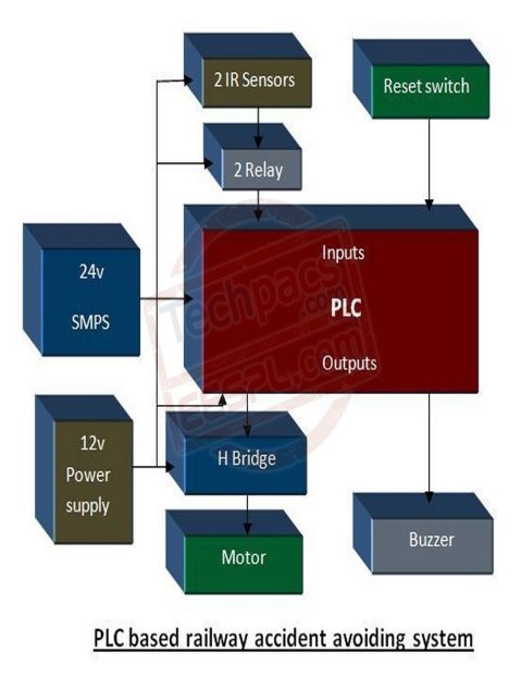
- COMPONENTS:
- PLC (PROGAMMABLE LOGIC CONTROLLER) -1015 WITH COMMUNICATION PORT
- 4-CHANNEL RELAY 24V
- IC7812
- DC SHUNT MOTOR 30rpm
- PHOTOELECTRIC SENSORS (PNP)
- INDICATING LAMPS
- PUSH BUTTONS
- TOGGLE SWITCH
- TRAIN
PLC(PROGRAMMABLE LOGIC CONTROLLER)
Presentation
Disentanglement of building and exact control of assembling procedure can bring about noteworthy cost reserve funds. The most financially savvy way, which can pay enormous profits over the long haul, is adaptable computerization; an arranged approach towards coordinated control frameworks. It requires a cognizant exertion with respect to plant chiefs to recognize ranges where mechanization can bring about better organization/use of HR and reserve funds in worker hours, down time. Mechanization require not be high finished and excessively modern; it is the staged, well ordered push to robotize, utilizing control frameworks custom fitted to one’s particular prerequisites that accomplishes the most alluring outcomes. That is the place Industrial hardware has been a leap forward in the field of computerization and control procedures.
Part OF ELECTRONICS IN AUTOMATION
A steady interest for better and more proficient assembling and process hardware has prompted the necessity for higher quality and unwavering quality in control systems. With the accessibility of shrewd, smaller strong state electronic gadgets, it has been conceivable to give control frameworks that can lessen upkeep, down time and enhance efficiency to an extraordinary broaden. By introducing effective and easy to understand mechanical gadgets frameworks for assembling apparatus or processors, one can get an exact, solid and productive means for creating quality items.
Considering the differed request and expanding rivalry, one needs to accommodate adaptable assembling process. One of the most recent systems in strong state controls that offers adaptable and effective operation to the client is “PROGRAMMABLE CONTROLLERS”. The fundamental thought behind these programmable controllers was to give intends to take out high cost related with unyielding, regular transfer controlled frameworks. Programmable controllers offer a framework with PC adaptability:
1. Suited to withstand the modern condition
2. Has effortlessness of operation
3. Maintenance by plant professionals and
4. Reduce machine down time and give expandability to future
DEFINATION OF PLC
A Programmable controller is a strong state client programmable control framework with capacities to control rationale, sequencing, timing, number juggling information control and tallying abilities. It can be seen as a mechanical PC that has a focal processor unit, memory, input yield interface and a programming gadget. The focal preparing unit gives the insight of the controller. It acknowledges information, status data from different detecting gadgets like utmost switches, closeness switches, executes the client control program store in the memory and gives suitable yield orders to gadgets like solenoid valves, switches and so forth.
Input yield interface is the correspondence connect between field gadgets and the controllers; field gadgets are wired to the I/O interfaces. Through these interfaces the processor can detect and measure physical amounts with respect to a machine or process, for example, closeness, position, movement, level, temperature, weight, and so on. In light of status detected, the CPU issues charge to yield gadgets, for example, valves, engines, cautions, and so on.
Software engineer unit gives the man machine interface. It is utilized to enter the application program, which regularly utilizes a straightforward easy to use rationale.
3.1.3 BENEFITS OF PROGRAMMABLE CONTROLLERS
1. Programmable controllers are made of strong state parts and thus give high dependability.
2. They are adaptable and changes in grouping of operation can without much of a stretch be fused because of programmability. They might be measured in nature and accordingly expandability and simple establishment is conceivable.
3. Use of PLC results in obvious reserve funds in Hardware and wiring cost.
4. They are conservative and possess less space.
1. Eliminate equipment things like Timers, counters and Auxiliary transfers. The nearness for clocks and counters has simple openness.
2. PLC can control an assortment of gadgets and kills the requirement for modified controls.
3. Easy demonstrative offices are given as a piece of the framework. Finding of the outside frameworks additionally turns out to be extremely straightforward. Accordingly simple administration/upkeep.
4. Programming gadgets give administrator amicable interface the machine. Being a result of the most recent craft of hardware innovation, Programmable controllers give larger amount of execution with PCs is conceivable. Valuable administration information can be gotten and kept up.
5. It has add up to securities against out of date quality and has wide extension for upgradation
A programmable rationale controller (PLC) is a modern PC control framework that consistently screens the condition of information gadgets and settles on choices in light of a custom program to control the condition of yield gadgets.
Any creation line, machine capacity, or process can be significantly improved utilizing this sort of control framework. Nonetheless, the greatest advantage in utilizing a PLC is the capacity to change and reproduce the operation or process while gathering and imparting key data.
Another favorable position of a PLC framework is that it is measured. That is, you can blend and match the sorts of information and Output gadgets to best suit your application.
3.1.3 History of PLCs
- The first Programmable Logic Controllers were composed and created by Modicon as a hand-off re-placer for GM and Landis.
- These controllers wiped out the requirement for rewiring and including extra equipment for each new arrangement of rationale.
- The new framework radically expanded the usefulness of the controls while decreasing the bureau space that housed the rationale.
- The first PLC, demonstrate 084, was imagined by Dick Morley in 1969.
- The first business fruitful PLC, the 184, was presented in 1973 and was outlined by Michael Greenberg.
3.1.4 Advantages of PLCs
PLCs not exclusively are fit for playing out an indistinguishable assignments from hard-wired control, but on the other hand are fit for some more intricate applications. Furthermore, the PLC program and electronic correspondence lines supplant a significant part of the interconnecting wires required by hard-wired control. Hence, hard-wiring, however still required to associate handle gadgets, is less escalated. This additionally makes amending mistakes and adjusting the application less demanding.
A portion of the extra focal points of PLCs are as per the following:
- Smaller physical size than hard-wire arrangements.
- Easier and speedier to roll out improvements.
- PLCs have incorporated diagnostics and abrogate capacities.
- Diagnostics are halfway accessible.
- Applications can be promptly recorded.
- Applications can be copied speedier and less extravagantly.
3.2 Inside A PLC
The Central Processing Unit (CPU) contains an inside program that advises the PLC how to play out the accompanying capacities:
- Execute the Control Instructions contained in the User’s Programs. This program is put away in “nonvolatile” memory, implying that the program won’t be lost if power is evacuated
- Communicate with different gadgets, which can incorporate I/O Devices, Programming Devices, Networks, and even different PLCs.
- Perform Housekeeping exercises, for example, Communications, Internal Diagnostics, and so forth
Fig 3.1 inside PLC
CPU
The microchip or processor module is the cerebrum of a PLC framework. It comprises of the microchip, memory coordinated circuits, and circuits important to store and recover data from memory. It likewise incorporates correspondences ports to different peripherals, other PLC’s or programming terminals. Today’s processors fluctuate broadly in their capacities to control genuine gadgets. Some control as few as 6 sources of info and yields (I/O) and others at least 40,000. One processor can control more than one process or assembling line. Processors are regularly connected together keeping in mind the end goal to give coherence all through the procedure. The quantity of sources of info and yields PLCs can control are constrained by the general limit of the PLC framework equipment and memory capacities. The occupation of the processor is to screen status or condition of info gadgets, check and explain the rationale of a client program, and control on or off condition of yield gadgets.
Smash
Smash or Random Access Memory is an unstable memory that would lose its data if power were expelled. This is the reason some processor units consolidate a battery move down. The sort of RAM ordinarily utilized is CMOS or Complementary Metal Oxide Semiconductor. CMOS RAM is utilized for capacity of the client’s program (step rationale outlines) and capacity memory.
ROM
ROM or Read Only Memory is a non-unstable kind of memory. This implies you needn’t bother with an outer power source to keep data. In this kind of memory, data can be perused, yet not changed. Thus the make now and again calls this firmware. It is put there for the inside utilize and operation of processor units.
EEPROM
EEPROM or Electrically Erasable Programmable Read Only Memory is normally an extra memory module that is utilized to move down the primary program in CMOS RAM of the processor. By and large, the processor can be modified to stack the EEPOM’s program to RAM if RAM is lost or adulterated.
Input Module
There are many sorts of info modules to browse. The sort of information module utilized is reliant upon what true contribution to the PLC is fancied. A few cases of data sources are point of confinement switches, electric eyes, and pushbuttons. DC sources of info, for example, thumbwheel switches, can be utilized to enter whole number qualities to be controlled by the PLC. DC input cards are utilized for this application. Since most modern power frameworks are naturally boisterous, electrical disengagement is given between the info and the processor. Electromagnetic obstruction (EMI) and Radio Frequency Interference (RFI) can bring about extreme issues in most strong state control frameworks. The segment utilized regularly to give electrical seclusion inside I/O cards is called an optical isolator or pick coupler. The wiring of an info is not mind boggling. The question is to get a voltage at a specific point on the card. Normally there are 8 to 32 input focuses on any one information module. Each point will be doled out a one of a kind address by the processor. Simple info modules are uncommon information cards that utilization simple to computerized transformation (A to D) to detect factors, for example, temperature, speed, weight, and position. The outside gadget ordinarily is associated with a controller (transducer) delivering an electrical flag the simple info card can translate. This flag is generally 4 to 20 Ma or a 0 to 10 volt flag.
Yield Module
Yield modules can be for utilized for air conditioning or dc gadgets, for example, solenoids, transfers, contractual workers, pilot lights, and LED readouts. Yield cards as a rule have from 6 to 32 yield focuses on a solitary module. The yield gadget inside the card gives the association from the client control supply to the heap. Typically silicon controlled rectifiers (SCR), triac, or dry contact transfers are use for this reason. Singular yields are appraised regularly at 2 to 3 amperes. Yield cards, similar to info cards have electrical detachment between the heap being associated and the PLC. Simple yield cards are an exceptional kind of yield modules that utilization computerized to simple change (D to A). The simple yield module can take an esteem put away in a 12 bit document and change over it to a simple flag. Regularly this flag is 0 – 10 volts dc or 4 to 20 Ma. This simple flag is regularly utilized as a part of gear, for example, engine worked valves and pneumatic position control gadgets
Fig 3.2 plc square chart
3.3 PLC OPERATION
There are four fundamental strides in the operation of all PLCs : which consistently happen in a rehashing circle.
- Input Scan
- Program Scan
- Output Scan
- Housekeeping
Fig 3.3 plc program cycle
Input Scan : Detects the condition of all information gadgets that are associated with the PLC
Program Scan : Executes the client made program rationale.
Output Scan : Energizes or de-stimulate all yield gadgets that are associated with the PLC.
Housekeeping : This progression incorporates interchanges with programming terminals, inner diagnostics and so forth…
CHECK INPUT STATUS : First the PLC investigates each contribution to decide whether it is on or off. As such, is the sensor associated with the main contribution on? At that point the second information? At that point the third et cetera… . It records this information into its memory to be utilized amid the following stride.
EXECUTE PROGRAM : Next the PLC executes your program one guideline at any given moment. Perhaps the program says that if the main info was on then it ought to turn on the principal yield. Since it definitely knows which sources of info are on/off from the past stride it will have the capacity to choose whether the principal yield ought to be turned on in light of the condition of the primary information. It will store the execution comes about for utilize later amid the following stride.
Refresh OUTPUT STATUS : Finally the PLC refreshes the status of the yields. It refreshes the yields in view of which data sources were on amid the initial step and the aftereffects of executing your program amid the second step. In light of the case in step 2 it would now turn on the principal yield on the grounds that the primary information was on and your program said to turn on the main yield when this condition is valid.
After the third step the PLC backpedals to step one and rehashes the means constantly. One sweep time is characterized as the time it makes to execute the 3 strides recorded previously.
Interchanges
There are a few techniques to impart between a PLC and a software engineer or even between two PLCs. Correspondences between a PLC and a software engineer (PC or Hand held) are given by the producers and you just need to connect to a link from your PC to the programming port on the PLC. This correspondence can be RS232; RS485 or TTY. Correspondences between two PLCs can be done by devoted connections provided/modified by the producers (RS232 and so forth) or through yields from one PLC to the contributions on another PLC. This immediate connection strategy for correspondence can be as basic as, if a yield on the main PLC is on then the comparing contribution on the second PLC will be on and afterward this information is utilized inside the program on the second PLC.
On the off chance that an expression of information/yields (16 bits) are utilized then numerical information can be exchanged from one PLC to the next (allude back to the segment on numbering frameworks).
There are numerous different strategies for correspondence amongst PLCs and furthermore from PLC to PC. Allude to the manuals provided with the PLC that you are utilizing for full subtle elements on interchanges.
3.4 PLC PROGRAMMING
Different dialects are utilized for programming of PLCs :
3.4.1 Ladder graph (LD)
Step chart is a realistic programming dialect gotten from the circuit outline of straightforwardly wired transfer controls. The stepping stool graph contains contact rails to one side and the privilege of the chart; these contact rails are associated with exchanging components (regularly open/typically shut contacts) by means of current ways and loop components.
Fig 3.4 stepping stool chart
Work piece chart (FBD)
In the capacity piece chart, the capacities and capacity squares are spoken to graphically and interconnected into systems. The capacity piece chart begins from the rationale outline for the plan of electronic circuits.
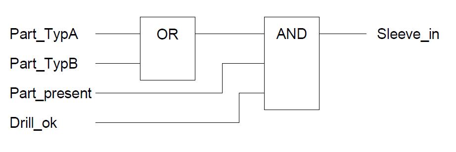
Fig 3.5 Functional block
Consecutive capacity outline (SFC)
The consecutive capacity outline is a dialect asset for the organizing of grouping focused control programs. The components of the consecutive capacity graph are steps, moves, option and parallel spreading. Each progression speaks to a handling status of a control program, which is dynamic or latent. A stage comprises of activities which, indistinguishable to the moves, are detailed in the IEC 1131-3 dialects. Activities themselves can again contain grouping structures. This component allows the various leveled structure of a control program. The consecutive capacity graph is in this way a phenomenal apparatus for the plan and organizing of control projects.
Direction list (IL)
Proclamation rundown is a literary constructing agent sort dialect described by a basic machine demonstrate (processor with just a single enroll). Guideline rundown is figured from control directions comprising of an administrator and an operand.
LD Part_TypeA
Or, then again Part_TypeB
Furthermore, Part_present
Furthermore, Drill_ok
ST Sleeve_in
With respect to dialect theory, the stepping stool chart, the capacity piece graph and guideline list have been characterized in the way they are utilized as a part of today’s PLC innovation. They are however constrained to essential capacities to the extent their components are concerned. This isolates them basically from the organization tongues utilized today. The aggressiveness of these dialects is kept up because of the utilization of capacities and capacity squares.
Organized (ST)
Organized is abnormal state dialect in view of Pascal, which comprises of expressions and guidelines. Directions can be characterized in the primary as : Selection guidelines, for example, IF…THEN…ELSE and so forth., redundancy guidelines, for example, FOR, WHILE and so on and work square summons.
Sleeve_in := (Part_TypeA OR Fig. B5.7: Part_TypeB) AND Part_present AND Drill_ok;
Organized empowers the detailing of various applications, past unadulterated capacity innovation, for example, algorithmic issues (highorder control calculations and so on.) and information dealing with (information investigation, preparing of complex information structures and so forth.)
3.4.2 LADDER LOGIC
Step Logic, or Ladder Diagrams is the most widely recognized programming dialect used to program a PLC.
Fig 3.6 step rationale
Step rationale was one of the principal programming approaches utilized as a part of PLCs in light of the fact that it acquired intensely from the Relay Diagrams that plant circuit repairmen definitely knew.
The images utilized as a part of Relay Ladder Logic comprises of a power rail to one side, a moment control rail to one side, and individual circuits that interface the left power rail to one side. The rationale of each circuit (or rung) is settled from left to right. The images of these graphs resemble a stepping stool – with two side rails and circuits that look like rungs on a stepping stool.
The photo above has a solitary circuit or “rung” of stepping stool.
If Input1 is ON (or genuine) – control (rationale) finishes the circuit from the left rail to the correct rail – and Output1 turns ON (or genuine).
If Output1 is OFF (or false) – then the circuit is not finished and rationale does not stream to one side – and Output 1 is OFF.
There are numerous rationale images accessible in Ladder Logic – including Timers, Counters, Math, and Data Moves – with the end goal that any coherent condition or control circle can be spoken to in Ladder Logic. With only a modest bunch of fundamental images – a Normally Open Contact, Normally Closed Contact, Normally Open Coil, Normally Closed Coil, Timer, Counter – most consistent conditions can be spoken to.
3.4.3 CONTACTS AND COILS
With simply the Normally Open Contact and Normally Open Coil – an astonishing cluster of fundamental sensible conditions can be spoken to.
Typically Open Contact. This can be utilized to speak to any contribution to the control rationale – a switch or sensor, a contact from a yield, or an inward yield.
Whenever “understood” the referenced info is analyzed for an ON (consistent 1) condition. On the off chance that it is ON, the contact will close and permit control (rationale) to spill out of left to right. On the off chance that the status is OFF (sensible 0), the contact is Open, control (rationale) won’t spill out of left to right.
Fig 3.7 NO contact fig 3.7 NO curl
Regularly Open Coil. This can be utilized to speak to any discrete yield from the control rationale. Whenever “fathomed” if the rationale to one side of the loop is TRUE, the refrenced yield is ON (consistent 1).
Comprehending a Single Rung
Assume a change is wired to Input1, and a light is wired through Output1 such that the light is OFF when Output1 is OFF, and ON when Output1 is ON.
At the point when Input1 is OFF (consistent 0) the contact stays open and power can’t spill out of left to right. Along these lines, Output1 stays OFF (consistent 0).
At the point when Input1 is ON (sensible 1) then the contact closes, control streams from left to right, and Output1 progresses toward becoming ON (the light turns ON).
The AND Rung
The AND is an essential thing rationale condition that is anything but difficult to straightforwardly speak to in Ladder Logic.
Fig3.8 AND ring
Assume a change is wired to Switch1, a moment switch is wired to Switch2, and a light is wired through Light1 such that the light is OFF when Light1 is OFF, and ON when Light1 is ON.
With the goal for Light1 to turn ON, Switch1 must be ON, AND Switch2 must be ON.
On the off chance that Switch1 is OFF, power (rationale) spill out of the left rail, however stops at Switch1. Light1 will be OFF paying little mind to the condition of Switch2.
On the off chance that Switch1 is ON, power makes it to Switch2. In the event that Switch2 is OFF, power can’t stream any further to one side, and Light1 is OFF.
In the event that Switch1 is ON, AND Switch2 is ON – control streams to Light1 fathoming its state to ON.
The OR Rung
The OR is a legitimate condition that is anything but difficult to speak to in Ladder Logic.
Fig 3.9 OR rung
Assume a change is wired to Switch1, a moment change is wired to Switch2, and a light is wired through Light1 such that the light is OFF when Light1 is OFF, and ON when Light1 is ON. In this occasion, we need to the light to turn ON if either Switch1 OR Switch2 is ON.
On the off chance that Switch1 is ON – control streams to Light1 turning it ON.
In the event that Switch2 is ON – control moves through the Switch2 contact, and up the rail to Light1 – turning it ON.
In the event that Switch1 AND Switch 2 are ON – Light1 is ON.
The main way Light1 is OFF is if Switch1 AND Switch2 are OFF.
* Another arrangement of essential contacts and loops that can be utilized as a part of Ladder Logic are the Normally Closed Contact and the Normally Closed Coil. These work simply like their ordinarily open partners – just in the inverse.
Whenever “tackled” the referenced information is analyzed for an OFF condition. On the off chance that the status is OFF (consistent 0) control (rationale) will spill out of left to right. In the event that the status is ON, power won’t stream.
Whenever “tackled” if the curl is an intelligent 0, power will be swung on to the gadget. In the event that legitimate 1, power will be OFF.
3.4.4 TIMERS AND COUNTERS
Commonly we will need to make a move in a control program in light of more than the conditions of discrete data sources and yields. Here and there, we will need to turn something on after a deferral, or check the quantity of times a switch is hit. To do these basic errands, we will require Timers and Counters.
Basic Timers (TIM)
A clock is essentially a control square that takes an info and changes a yield in light of time. There are two fundamental clock sorts we will manage at first (there are other propelled clocks, however we will begin with the nuts and bolts first) – On-Delay Timer and the Off-Delay Timer.
On-Delay Timer – this clock takes an info, holds up a particular measure of time, then turns ON a yield (or enables rationale to stream after the deferral).
Off-Delay Timer – this clock alternates ON a yield (or enables rationale to stream) and keeps that yield ON until the set measure of time has passed, then turns it OFF (thus off-deferral)
Basic Counter (CNT)
A counter just tallies the quantity of occasions that happen on an information. There are two fundamental sorts of counters – Up counter and a Down counter.
Up Counter – as its name infers, at whatever point an activating occasion happens, an up counter augmentations the counter.
Down Counter – at whatever point an activating occasion happens, a down counter decrements the counter.
Fig 3.10 counter
Engine STARTER EXAMPLE :
Initially consider a hardwired approach.
The accompanying line chart outlines how a typically open and an ordinarily shut pushbutton may be associated with control a three-stage AC engine. In this case, an engine starter loop (M) is wired in arrangement with a typically open, passing Start pushbutton, an ordinarily shut, transient Stop pushbutton, and regularly shut over-burden hand-off (OL) contacts.
squeezing the Start pushbutton finishes the pathmfor current stream and invigorates the engine starter (M). This shuts the related M and Ma (assistant contact situated in the engine starter) contacts. At the point when the Start catch is discharged, current keeps on moving through the Stop catch and the Ma contact, and the M loop remains empowered.
The engine will keep running until the regularly shut Stop catch is squeezed, unless the over-burden transfer (OL) contacts open. At the point when the Stop catch is squeezed, the way for current stream is interfered with, opening the related M and Ma contacts, and the engine stops
Fig 3.11
Presently consider PLC approach :
This engine control application can likewise be refined with a PLC. In the accompanying case, an ordinarily open Start pushbutton is wired to the principal input (I0.0), a typically shut Stop pushbutton is wired to the second information (I0.1), and regularly shut over-burden hand-off contacts (some portion of the engine starter) are associated with the third info (I0.2). These sources of info are utilized to control typically open contacts in a line of stepping stool rationale modified into the PLC.
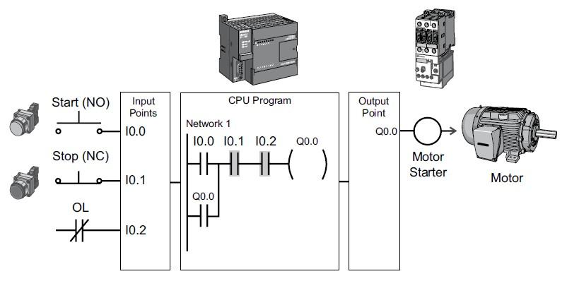
Fig 3.12
At first, I0.1 status bit is a rationale 1 in light of the fact that the typically shut (NC) Stop Pushbutton is shut. I0.2 status bit is a rationale 1 on the grounds that the typically shut (NC) over-burden transfer (OL) contacts are shut. I0.0 status bit is a rationale 0, be that as it may, in light of the fact that the typically open Start pushbutton has not been squeezed. Typically open yield Q0.0 contact is additionally customized on Network 1 as a fixing contact. With this straightforward system, stimulating yield curl Q0.0 is required to turn on the engine.
The Operation
At the point when the Start pushbutton is squeezed, the CPU gets a rationale 1 from information I0.0. This causes the I0.0 contact to close. Each of the three sources of info are presently a rationale 1. The CPU sends a rationale 1 to yield Q0.0. The engine starter is empowered and the engine begins.

Fig 3.13
The yield status bit for Q0.0 is presently a 1. On the following sweep, when regularly open contact Q0.0 is tackled, the contact will close and yield Q0.0 will remain on regardless of the possibility that the Start pushbutton is discharged.
At the point when the Stop pushbutton is squeezed, input I0.1 kills, the I0.1 contact opens, yield loop Q0.0 de-stimulates, and the engine kills

Fig 3.14

Fig 3.15
4.1 RELAY
A transfer is an electromechanical gadget that is activated by an electrical current. The present streaming in one circuit causes the opening or shutting of another circuit. Profoundly complex transfers are used to secure electric power frameworks against inconvenience and power outages and in addition to manage and control the era and appropriation of energy. In the home, transfers are utilized as a part of various apparatuses like fridges, clothes washers and dishwashers, and warming and cooling controls.
Each transfer contains a detecting unit, the electric curl, which is fueled by AC or DC current. At the point when the connected current or voltage surpasses a limit esteem, the curl actuates the armature, which works either to close the open contacts or to open the shut contacts. At the point when a power is provided to the loop, it produces an attractive drive that impels the 6 switch instrument. The attractive drive is, in actuality, handing-off the activity starting with one circuit then onto the next. The main circuit is known as the control circuit while the second is known as the heap circuit. There are three vital elements of a hand-off: On/Off Control, Limit Control and Logic Operation. On/Off Control: Example: Air molding control, used to point of confinement and control a “powerful” load, for example, a compressor Limit Control:
Illustration: Motor Speed Control, used to disengage an engine on the off chance that it runs slower or quicker than the coveted speed Logic Operation: Example: Test Equipment, used to associate the instrument to various testing focuses on the gadget under test Fig 2.1 – Simple Relay Circuit 2.2.1 Types of Relays There are two essential sorts of transfers: Electromechanical and Solid State.
Electromechanical transfers have moving parts, while strong state transfers have no moving parts. Focal points of Electromechanical transfers incorporate lower cost, no warmth sink is required, numerous shafts are accessible, and they can switch AC or DC effortlessly. An.) Electromechanical Relays General Purpose Relay: The universally useful hand-off is evaluated by the measure of current its switch contacts can deal with. Most forms of the universally useful transfer have one to eight shafts and can be single or twofold toss. These are found in PCs, duplicate machines, and other buyer electronic gear and apparatuses.
Control Relay: The power transfer is fit for dealing with bigger power loads – 10-50 amperes or more. 7 They are generally single-shaft or twofold post units. Contractual worker: A unique kind of high power transfer, it’s utilized for the most part to control high voltages and streams in modern electrical applications. On account of these powerful necessities, contactors dependably have twofold make contacts. Time-Delay Relay: The contacts won’t not open or close until at some point interim after the loop has been empowered. This is called delay-on-work. Delay-on-discharge implies that the contacts will stay in their activated position until some interim after the power has been expelled from the curl.
A third postponement is called interim planning. Contacts return to their substitute position at a particular interim of time after the loop has been empowered. The planning of these activities might be a settled parameter of the transfer, or balanced by a handle on the hand-off itself, or remotely balanced through an outer circuit. Fig 2.2:- Electromechanical Relay B.) Solid State Relays:- These dynamic semiconductor gadgets utilize light rather than attraction to incite a switch. The light originates from a LED, or light discharging diode. At the point when control power is connected to the gadget’s yield, the light General Purpose Relay is turned on and sparkles over an open space. On the heap side of this space, a piece of the gadget detects the nearness of the light, and triggers a strong state switch that either opens or shuts the circuit under control. Regularly, strong state transfers are utilized where the circuit under control must be secured .
The contacts are the most imperative parts of a transfer. Their attributes are essentially influenced by components, for example, the material of the contacts, voltage and current qualities connected to them (particularly, the voltage and current waveforms when invigorating and de-stimulating the contacts), the sort of load, working recurrence, and bob. On the off chance that any of these variables neglect to fulfill a foreordained esteem, issues, for example, metal corruption between contacts, contact welding, wear, or a quick increment in the contact resistance may happen. The amount of electrical current that moves through the contacts specifically impacts the contacts’ qualities. For instance, when the hand-off is utilized to control an inductive load, for example, an engine of a light. The contacts will wear speedier and metal deterioration between the mating contacts will happen all the more regularly as the inrush current to the contacts increments.
2.3 RELAY BOARD: –
The transfer board is the thing that powers the exchanging mechanics on your electronic gadgets. It contains a power supply circuit, administrative hardware and obviously the transfers that you have to turn parts or the greater part of your gadget (or gadgets) on and off – or to switch them between states. Regularly, the transfers on your hand-off board will be strong state, dissimilar to the mechanical transfers that you may see in bigger electrical applications (like, for instance, the change you divert to turn from a staged power hand-off, or the breakers in your home’s hardware). Strong state transfers are dependable over a more extended term than electro mechanical transfers on account of the basic certainty that they have no moving parts (thus the name strong state), which methods for course that nothing can seize up or sever and counteract effective operation.
The SSR on your transfer board will contain a transistor or various transistors, through which the switch of state is made. Early strong state transfers endured a drop in voltage over their transistors, yet present day SSRs 9 are equipped for conveying exchanging loads with substantially higher streams. The wording with which one’s transfer board will be depicted and additionally talked about in manuals, exhortation and writing is a similar phrasing that you will discover for the discourse of any electronic or electric switches. The fundamental capacity of the transfers on your hand-off board is to flick between one or a few shafts. This is finished by tossing contacts between them (“shaft” and “toss” are the electrical exchanging terms we’re keen on here). The greater part of the wording portraying the condition of the contacts in your transfer board is compacted into acronymic shape: NO (Normally Open); NC (Normally Closed); and Change Over or Double Throw (alluded to either as CO or DT, both of which mean a similar thing). A Normally Open contact is one that is generally separated – so in its resting or latent express the contact is open.
A Normally Closed contact has the inverse trademark: in its resting state the circuit is associated and dynamic on the grounds that the hand-off has shut on the contact. A Change Over or Double Throw contact associates two connected circuits – one Normally Open and the other Normally Closed. The switch on your transfer board tosses the shaft between the Normally Open and the Normally Closed circuit when the switch is enacted.
The elements of the switches on your transfer board depend (actually) on your application. When all is said in done terms they are normally used to build control where there is a feeble power source (enhancement, more often than not of a flag); to separate a controlled and controlling circuit from each other; to change to a standby power state; to execute a period delay; or to control rationale inside your electronic hardware. A progression of Normally Open contacts on a transfer board is equivalent to AND; a parallel association of Normally Open contacts moves toward becoming OR. Fig 2.5:- 8-Channel Relay Board
A hand-off is an electrical switch that opens and closes under the control of another electrical circuit. In the first shape, the switch is worked by an electromagnet to open or close one or many arrangements of contacts. A hand-off can control a yield circuit of higher power than the information circuit, it can be thought to be, in a wide sense, a type of an electrical enhancer. So a transfer can be characterized as a programmed electromagnetic/electronic switch, which can be utilized to represent the moment of truth the circuit. The itemized depiction of the hand-off is given in the further parts. In this venture transfer is utilized to control the pumping DC engine.
Programmed control of the operation of any establishment infers that the establishments being controlled is observed, administered and secured by it’s own methods without manual obstruction. The transfer is a gadget which control the exchanging of circuits by accepting a vitality to work itself. In can be considered as remote control switch.
Electromagnetic transfers give a from ON to OFF when the curl is empowered or deenergized.
Transfers can be hermetically fixed to shield them from dust,oxidation and so forth.
The fundamental element in a transfer is contacts. They close the electric circuit. or, then again open an electric circuit under the control of an electromagnet.
Littler transfers work speedier on the grounds that the moving parts need to travel a littler separation. Additionally the inductance is decreased.
CLASSIFICATION OF RELAYS :
The function of construction of relays are different and they can be classified accordingly. The main difference between switches and relays is, switches are manually operated whereas relays are electrically operated. Relay contacts are categorized into No (normally open) and NC (normally closed) types.
CLASSIFICATION OF RELAYS
1.General Miniature
Purpose (i) sealed (ii) Unsealed
2.Speed Latching relay (i) conventional
(ii) Mechanical
(iii) Dry reed
(iv) Magnetic
(v) Mercury
3 special purposeThermal
- High Voltage
- High frequency
- Frequency sensitive
- Time relay
- Stepping relay
- Proximity relay
- Vacuum relay
Basically relays can be called as light, medium or heavy duty
general purpose relays. Mostly they are known by their functions.
ELECTROMAGNETIC RELAY
- Moving type
- Rotary type
- Reed type
- Moving coil type
- Induction type
 Relays can further be divided as :
General purpose relay
- Current relay
- Power & voltage relay
- Reactance relay
- Impedance relay
- Gas pressure relay
- Acoustic relay
- Optical relay
- Chemical relay
- Time delay relay
- Sequence relay
- Stepping relay
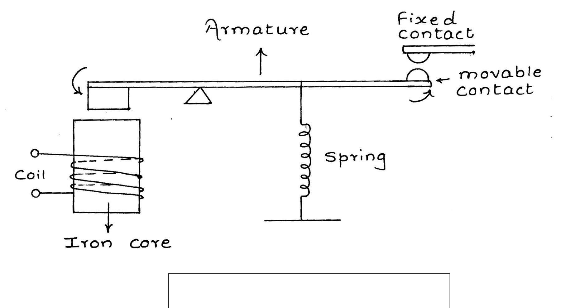
GENERAL PURPOSE RELAY
Fig 4.1
The sealed relays are hermetically sealed. Coils which are wound on bobbins are covered with varnish and are sealed inside containers with leads brought out through seals.
Miniature relays are also enclosed in metal cans with typical
dimensions of 1” ¾” ½” and are known as ‘Crystal Can’ relays or ‘Postage Stamp’ relays. Typical contact rating for miniature relay is 1 amp at 28 V dc.
Micro miniature relays are still smaller with dimensions of 8 mm x 10 mm x 12 mm. They are normally used for printed circuit. boards where the leads can be directly mounted. Rating is 0.5 amp at 28 v dc for resistive load.
AC OPERATED RELAY :
The application of these relays is well known. They are used for switching on 50 HZ equipments like motors and industrial loads. When a. c. flux passes through the armature gap due to nature of a.c. it passes through Zero and chatter is observed.
DIFFERENTIAL RELAY :
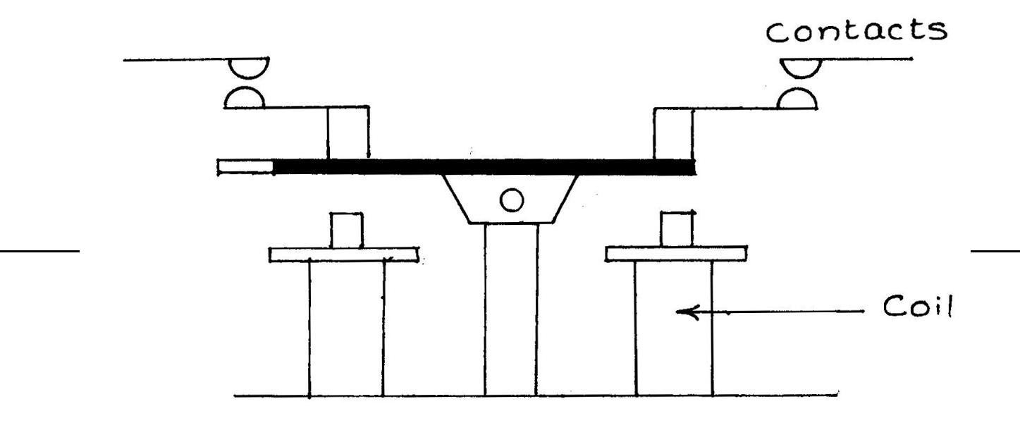 As shown in the fig., the two windings operate the relay only when there is difference in voltage or current. This relay is ideal for comparing.
DIFFERENTIAL RELAY Fig 4.3
We have seen the bimetal type of thermal relay, similarly there are relays that work on the principle of expansion.
A special steel wire is wound between two bobbins that are insulated. When switched on, heat is produced due to current which expands the wire. This expansion causes lever operation and contact is closed.
TELEPHONE RELAYS :-
These can be used for d.c. as well as a.c. operation for a.c. operations laminated cores are used to reduce losses. The telephone relay has L shaped frames which holds armature & coil. The contacts are normally interleaved and are separated by spaces which are made up of insulating material.
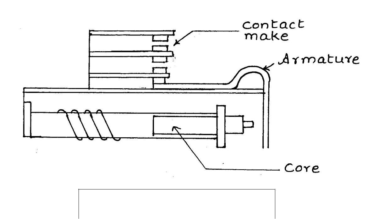
TELEPHONE RELAY
Fig 4.4
A relay is an electrical switch that opens and closes under control of another electrical circuit. In the original form, the switch is operated by an electromagnet to open or close one or many sets of contacts. These contacts can be either Normally Open (NO), Normally Closed (NC), or change-over contacts.
Normally-open contacts connect the circuit when the relay is activated; the circuit is disconnected when the relay is inactive. It is also called Form A contact or ―make‖ contact. Form A contact is ideal for applications that require to switch a high-current power source from a remote device.
Normally-closed contacts disconnect the circuit when the relay is activated; the circuit is connected when the relay is inactive. It is also called Form B contact or ―break‖ contact. Form B contact is ideal for applications that require the circuit to remain closed until the relay is activated.Change-over contacts control two circuits: one normally-open contact and one normally-closed contact with a common terminal. It is also called Form C contact.
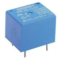
Fig 4.5 Relay
The electromagnetic relay, one of mankind‘s first electrical device, was used practically in telegraphy as early as 1850. The modern relay, properly applied, is one of the most simple, effective and dependable component available. In the majority of instances, it can achieve better reliability at lesser cost than an equivalent solid-state complex type of relay. The term ‗relay‘ was used for the first time to describe an invention made by Samuel Morse in 1836. The device invented by Morse was a ―Telegraph Amplifying Electromagnetic Device‖ which enabled a small current flowing in a coil to switch on a large current in another circuit and thus helped in―relay‖ of signals.
4.1.2 OPERATION
The hand-off utilized as a part of this venture work is electromagnetic hand-off. The electromagnetic transfer is essentially a switch (or a mix of switches) worked by the attractive drive produced by a present coursing through a curl. Basically, it comprises of four sections an electromagnet involving a loop and an attractive circuit, a versatile armature, an arrangement of contacts, and a casing to mount every one of these parts. Notwithstanding, wide scopes of transfers have been created to meet the prerequisites of the business. This hand-off is only a switch, which works electromagnetically.
It opens or shuts a circuit when current through the loop is begun or halted. At the point when the curl is stimulated armature is pulled in by the electromagnet and the contacts are shut. That is the way the power is connected to the signs (markers). The development of the run of the mill transfer contains a code encompassed by a curl of copper wire.
The center is mounted on a metal edge. The portable piece of the hand-off is called armature. At the point when a voltage is connected to the curl terminals, the present moving through the loop delivers an attractive field in the center. As such, the center goes about as an electromagnet and pulls in the metal armature. At the point when the armature is pulled in to the center, the attractive way is from the center through armature, through the edge, and back to the center. On evacuating the voltage the spring connected to the armature gives back the armature to its unique position. In this position, there is a little air-crevice in the attractive way. Henceforth, more power is expected to pull in the armature than that expected to keep it held in the pulled in position. The point by point portrayal of the transfer is given in the further parts..
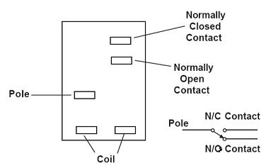
Fig 4.6
The required power supply for the entire module i.e., +5V and +12V DC is derived from the mains single phase supply of 230V AC.
4 CHANNEL RELAY BOARD
4 Channel Relay Board is a simple and convenient way to interface 4 relays for switching application in your project. Very compact design can fit in small area, manly this board is made for low voltage application. Features Input supply 12 VDC @ 170 mA Output four SPDT relay
Relay specification
- 10A/24V DC
- Trigger level2 ~ 5 VDC
- Header Connector for connecting power and trigger voltage
- LED on each channel indicates relay status
- Power Battery Terminal (PBT) for easy relay output and aux power connection
Applications: Robotics, Electronics projects, Industrial controls, Microwaves Oven, Fans, DC Motor, AC Lamp, Solenoids Remote Controls etc.
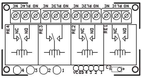
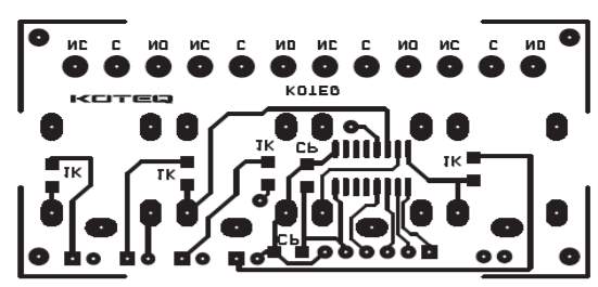
Fig 4.7
4.2 INTRODUCTION TO DC MOTORS
The brushed DC motor is one of the earliest motor designs. Today, it is the motor of choice in the majority of variable speed and torque control applications.
Advantages:
- Easy to understand design
- Easy to control speed
- Easy to control torque
- Simple, cheap drive design
- Easy to understand design
The design of the brushed DC motor is quite simple. A permanent magnetic field is created in the stator by either of two means:
- Permanent magnets
- Electro-magnetic windings
If the field is created by permanent magnets, the motor is said to be a “permanent magnet DC motor” (PMDC). If created by electromagnetic windings, the motor is often said to be a “shunt wound DC motor” (SWDC). Today, because of cost-effectiveness and reliability, the PMDC motor is the motor of choice for applications involving fractional horsepower DC motors, as well as most applications up to around three strength.
At five strength and more prominent, different types of the shunt wound DC engine are most usually utilized. This is on account of the electromagnetic windings are more financially savvy than lasting magnets in this power go.
Alert: If a DC engine endures lost field (if for instance, the field control associations are broken), the DC engine will promptly start to quicken to the top speed which the stacking will permit. This can bring about the engine flying separated if the engine is daintily stacked. The conceivable loss of field must be represented, especially with shunt wound DC engines.
Contradicting the stator field is the armature field, which is produced by a changing electromagnetic flux originating from windings situated on the rotor. The attractive posts of the armature field will endeavor to agree with the inverse attractive shafts produced by the stator field. In the event that we halted the plan now, the engine would turn until the shafts were inverse each other, sink into place, and after that stop – which would make a really pointless engine!
Nonetheless, we are more intelligent than that. The area of the rotor where the power enters the rotor windings is known as the commutator. The power is conveyed between the rotorand the stator by conductive graphite-copper brushes (mounted on the rotor) which contact rings on stator. Envision power is provided:
The engine pivots toward the post arrangement point. Similarly as the engine would get to this point, the brushes hop over a hole in the stator rings.
Energy conveys the engine forward over this hole. At the point when the brushes get to the opposite side of the hole, they contact the stator rings again and – the extremity of the voltage is switched in this arrangement of rings! The engine starts quickening once more, this time attempting to get to the inverse arrangement of shafts. (The force has conveyed the engine past the first post arrangement point.) This proceeds as the engine turns.
In most DC engines, a few arrangements of windings or perpetual magnets are available to smooth out the movement. Simple to control speed controlling the speed of a brushed DC engine is basic.
The higher the armature voltage, the quicker the revolution. This relationship is direct to the engine’s most extreme speed. The most extreme armature voltage which compares to an engine’s evaluated speed (these engines are generally given an appraised speed and a greatest speed, for example, 1750/2000 rpm) are accessible in certain standard voltages, which generally increment in conjunction with torque. Along these lines, the littlest mechanical engines are evaluated 90 VDC and 180 VDC. Bigger units are appraised at 250 VDC and now and again higher. Strength engines for use in portable applications are appraised 12, 24, or 48 VDC.
Other little engines might be evaluated 5 VDC. Most modern DC engines will work dependably over a speed scope of around 20:1 – down to around 5-7% of base speed. This is greatly improved execution than the tantamount AC engine.
This is halfway because of the straightforwardness of control, but on the other hand is somewhat because of the way that most modern DC engines are composed considering variable speed operation, and have included warmth scattering highlights which permit bring down working paces.
Simple to control torque
In a brushed DC engine, torque control is likewise straightforward, since yield torque is corresponding to current. In the event that you restrain the present, you have quite recently restricted the torque which the engine can accomplish. This makes this engine perfect for fragile applications, for example, material assembling.
Basic, shoddy drive outline
The consequence of this outline is that variable speed or variable torque gadgets are anything but difficult to plan and fabricate. Shifting the speed of a brushed DC engine requires minimal more than a sufficiently expansive potentiometer.
Practically speaking, these have been substituted for everything except sub-fragmentary torque applications by the SCR and PWM drives, which offer moderately decisively control voltage and current. Basic DC drives are accessible at the low end (up to 2 torque) for under US$100 – and some of the time under US$50 if accuracy is not vital. Expansive DC drives are accessible up to many torque. Be that as it may, over around 10 drive watchful thought ought to be given to the value/execution tradeoffs with AC inverter frameworks, since the AC frameworks demonstrate a value advantage in the bigger frameworks. (Be that as it may, they may not be equipped for the application’s execution prerequisites).
Disadvantages
- Expensive to produce
- Can’t reliably control at lowest speeds
- Physically larger
- High maintenance
- Dust
MAIN PARTS OF DC MOTOR
Armature
A D.C. motor consists of a rectangular coil made of insulated copper wire wound on a soft iron core. This coil wound on the soft iron core forms the armature. The coil is mounted on an axle and is placed between the cylindrical concave poles of a magnet.
Commutator
A commutator is used to reverse the direction of flow of current. Commutator is a copper ring split into two parts C1 and C2. The split rings are insulated form each other and mounted on the axle of the motor. The two ends of the coil are soldered to these rings.
They rotate along with the coil. Commutator rings are connected to a battery. The wires from the battery are not connected to the rings but to the brushes which are in contact with the rings.
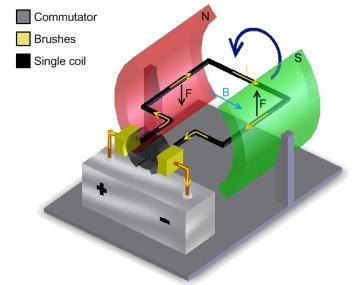
Fig: 4.8 Commutators Brushes
Two small strips of carbon, known as brushes press slightly against the two split rings, and the split rings rotate between the brushes. The carbon brushes are connected to a D.C. source.When the coil is powered, a magnetic field is generated around the armature. The left side of the armature is pushed away from the left magnet and drawn towards the right, causing rotation.
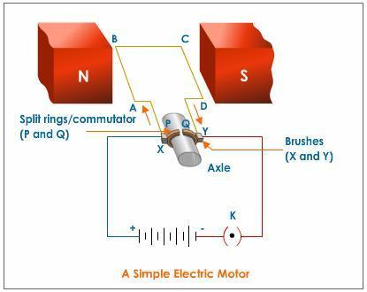
Fig: 4.9 Brushes
When the coil turns through 900, the brushes lose contact with the commutator and the current stops flowing through the coil. However the coil keeps turning because of its own momentum.
Now when the coil turns through 1800, the sides get interchanged. As a result the commutator ring C1 is now in contact with brush B2 and commutator ring C2 is in contact with brush B1. Therefore, the current continues to flow in the same direction.


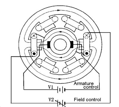
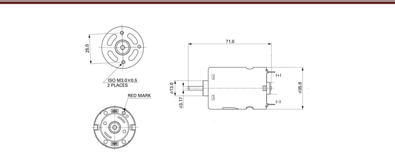
Fig: 4.10 Commutators and Commutator Ring PARAMETRS OF THE DC MOTRS:
- Direction of rotation
- Motor Speed
- Motor Torque
- Motor Start and Stop
Direction of Rotation:
A DC Motor has two wires. We can call them the positive terminal and the negative terminal, regardless of the way that these are fundamentally self-decisive names (not in the least like a battery where these polarities are vital and not to be mixed!). On a motor, we say that when the + wire is related with + terminal on a power source, and the – wire is related with the – terminal source on a comparative power source, the motor rotates clockwise (in case you are looking towards the motor shaft). If you alter the wire polarities so that each wire is related with the limiting power supply terminal, then the motor rotates counter clockwise. See this is just a self-self-assured decision and that some motor creators could without a lot of an extend pick the negating convention. For whatever period of time that you perceive what turn you get with one limit, you can essentially interface in such a frame, to the point that you get the heading that you require on a for every furthest point preface.
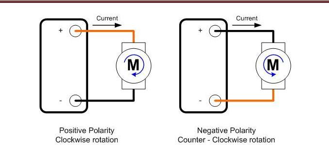
Fig: 4.11 Positive And Negative Counter Clockwise Rotation
DC Motor Rotation vs Polarity:
Facts:
DC Motor rotation has nothing to do with the voltage magnitude or the current magnitude flowing through the motor.
DC Motor rotation does have to do with the voltage polarity and the direction of the current flow.
4.2.3 WORKING OF DC MOTOR
PRINCIPLE
At the point when a rectangular curl conveying current is set in an attractive field, a torque follows up on the loop which turns it constantly.
At the point when the curl pivots, the pole connected to it likewise turns and hence it can do mechanical work.
Each DC engine has six fundamental parts – hub, rotor (a.k.a., armature), stator, commutator, field magnet(s), and brushes.
In most basic DC engines (and all that BEAMers will see), the outer attractive field is created by high-quality perpetual magnets1. The stator is the stationary piece of the engine – this incorporates the engine packaging, and in addition at least two perpetual magnet shaft pieces. The rotor (together with the pivot and appended commutator) turns as for the stator. The rotor comprises of windings (by and large on a center), the windings being electrically associated with the commutator. The above chart demonstrates a typical engine design – with the rotor inside the stator (field) magnets.
The geometry of the brushes, reporter contacts, and rotor windings are to such an extent that when power is connected, the polarities of the empowered winding and the stator magnet(s) are misaligned, and the rotor will turn until it is practically lined up with the stator’s field magnets. As the rotor achieves arrangement, the brushes move to the following reporter contacts, and stimulate the following winding. Given our case two-shaft engine, the revolution switches the course of current through the rotor twisting, prompting a “flip” of the rotor’s attractive field, driving it to keep turning.
All things considered, however, DC engines will dependably have more than two posts (three is an extremely normal number). Specifically, this maintains a strategic distance from “dead spots” in the commutator. You can envision how with our illustration two-shaft engine, if the rotor is precisely at the center of its turn (flawlessly lined up with the field magnets), it will get “stuck” there. In the interim, with a two-shaft engine, there is a minute where the commutator shorts out the power supply (i.e., both brushes touch both commutator contacts at the same time).
This would be terrible for the power supply, squander vitality, and harm engine parts also. However another hindrance of such a straightforward engine is, to the point that it would display a high measure of torque “swell” (the measure of torque it could deliver is cyclic with the position of the rotor).
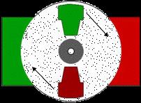
Fig4.12 Peripheral of dc motor
Construction and Working
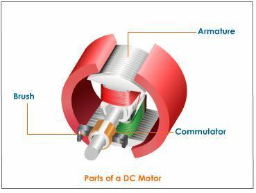
Fig: 4.13 Construction and working of dc motor
4.2.4 SPEED CONTROL OF DC Motor
Whereas the voltage polarity controls DC motor rotation, voltage magnitude controls motor speed. Think of the voltage applied as a facilitator for the strengthening of the magnetic field. In other words, the higher the voltage, the quicker will the magnetic field become strong. Remember that a DC motor has an electromagnet and a series of permanent magnets.
The applied voltage generates a magnetic field on the electromagnet portion. This electromagnet field is made to oppose the permanent magnet field. If the electromagnet field is very strong, then both magnetic entities will try to repel each other from one side, as well as attract each other from the other side. The stronger the induced magnetic field, the quicker will this separation/attraction will try to take place. As a result, motor speed is directly proportional to applied voltage.
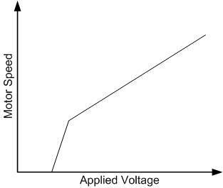
Fig: 4.14 Speed Curve of Dc Motor
Motor Speed Curve:
One aspect to have in mind is that the motor speed is not entirely lineal. Each motor will have their own voltage/speed curve. One thing I can guarantee from each motor is that at very low voltages, the motor will simply not move. This is because the magnetic field strength is not enough to overcome friction. Once friction is overcome, motor speed will start to increase as voltage increase.The following video shows the concept of speed control and offers some ideas on how this can be achieved.
Motor Torque:
In the previous segment I kind of described speed as having to do with the strength of the magnetic field, but this is in reality misleading. Speed has to do with how fast the magnetic field is built and the attraction/repel forces are installed into the two magnetic structures. Motor strength, on the other hand, has to do with magnetic field strength. The stronger the electromagnet attracts the permanent magnet, the more force is exerted on the motor load.
Per example, imagine a motor trying to lift 10 pounds of weight. This is a force that when multiplied by a distance (how much from the ground we are lifting the load) results in WORK. This WORK when exerted through a predetermined amount of time (for how long we are lifting the weight) gives us power. But whatever power came in, must come out as energycan not be created or destroyed. So that you know, the power that we are supplying to the motor is computed by P = IV
Where P is power, I is motor current and V is motor voltage
Hence, if the voltage (motor speed) is maintained constant, how much load we are moving must come from the current? As you increase load (or torque requirements) current must also increase.
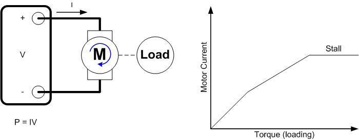
Fig: 4.15 Motor Torques Loading
Motor Loading
One aspect about DC motors which we must not forget is that loading or increase of torque cannot be infinite as there is a point in which the motor simply can not move. When this happens, we call this loading ―Stalling Torque‖. At the same time this is the maximum amount of current the motor will see, and it is refer to Stalling Current. Stalling deserves a full chapter as this is a very important scenario that will define a great deal of the controller to be used. I promise I will later write a post on stalling and its intricacies.
Motor Start and Stop
You are now knowledgeable on the best way to control the engine speed, the engine torque and the engine heading of revolution. In any case, this is all okay the length of the engine is really moving.
What about beginning it and halting it? Are these inconsequential matters? Could we simply disregard them or would it be a good idea for us to be watchful about these viewpoints also? You wager we should!Starting an engine is an extremely dangerous minute for the framework.
Since you have an inductance whose vitality stockpiling limit is fundamentally unfilled, the engine will initially go about as an inductor. It could be said, it ought not stress us a lot of in light of the fact that current can’t change unexpectedly in an inductor, however the reality of the situation is this is one of the occasions in which you will see the most elevated streams streaming into the engine. The begin is not really terrible for the engine itself as in actuality the engine can without much of a stretch take this Inrush Current. The power organize, then again and if not appropriately intended for, may get destroyed.
Once the engine has begun, the engine current will go down from inrush levels to whatever heap the engine is at. Per case, if the engine is moving a couple gears, current will be corresponding to that heap and as per torque/current bends.
Halting the engine is not as unforgiving as beginning. Actually, ceasing is essentially a breeze. What we do need to concern ourselves is with how we need the engine to stop. Do we need it to drift down as vitality is spent insider savvy, or do we need the rotor to stop as quick as could reasonably be expected? In the event that the later is the choice, then we require braking. Braking is effortlessly proficient by shorting the engine yields. The motivation behind why the engine stops so quick is on account of as a short is connected to the engine terminals, the Back EMF is shorted. Since Back EMF is specifically corresponding to speed, making Back EMF = 0, additionally implies making speed = 0.
5.1 PHOTOELECTRIC SENSOR
A photoelectric sensor, or photo eye, is an equipment used to discover the distance, absence, or presence of an object by using a light transmitter, often infrared, and a photoelectric receiver. They are largely used in industrial manufacturing. There are three different useful types: opposed (through beam), retro-reflective, and proximity-sensing
“Proximity sensor” includes all the sensors that perform sensing / detection non contact,compared with other sensors, such as limit switches, which detect objects with Physical contact him. Proximity Sensor change information about the movement or presence object into an electrical signal. There are three types of detection systems that perform these conversions:
1.System that uses eddy currents generated in the metal sensing object electromagnetic induction,
2. The system detects changes in the electrical capacity when approaching the object sensing.non-contact detection switch positions.
JIS provides the common name “proximity sensors” for all sensors that provide detection non-contact of the target object near or in the vicinity of the sensor, and classifiesthem as inductive, capacitive, ultrasonic, photoelectric, magnetic, etc. Technical Guide defines all inductive sensors are used to detect metal, capacitive sensors are used to detect metal objects andnon-metallic, and sensors that utilize DC magnetic field as Proximity Sensor.
Proximity (Inductif) sensors are widely used for equipment control inindustry. These sensors can replace mechanical switches / limit switch better.With this sensor will make it easier to construct control systems.
The working principle is Inductif Proximity Sensors detect objects that conduct the magnetic field / type of iron that is nearby. So when a proximity sensor that has been strung with power supply and the load brought to an iron object, then the sensor will give output to load.
Proximity sensor has a shape that various sorts, and described this time is cylindrical / cylindrical. Based on the shape of the sensor head, there are two (2)kinds of Shielded / Flush and Unshielded / Non-Flush. Shielded has a head the sensor flush with the body and vice versa (for more details see the table).
The shape of the head this sensor also affect the sensitivity of the sensing of the sensor, meaning that these differences also effect on sensing distance. Apart form the sensing distance of the sensor head is also very small sensors depending on the major.
5.1.1 Proximity Sensor Types
1. Based on the detected object consists of:
Inductive Proximity
Proximity mode that works based on inductance change if there is an object of metal / metal within the scope of the working area of the sensor. This mode can only detect metal objects just with the maximum detection distance of 6 cm. Metal base material greatly affect the ability of the sensor detection.
Capacitive Proximity
Proximity mode that works based on the capacity change objects that are in the work area coverage sensor. This mode can detect all kinds of objects and has a maximum distance of 2 cm.
Based on the input and output configurations
Proximity nothing disuply with DC voltage, AC or AC / DC. Output is NO, NC or NO / NC with two (2) wires or 3 (three) cable. Based on the input and output configuration consists of:
Current sourcing output (PNP)
When the sensor is inactive, the output-value logic zero. When the sensor is active, the output is worth a logic one.
Current sinking output (NPN)
When the sensor is inactive, the output is worth a logic one. When the sensor is active, the output-value logic zero.
capacitive proximity sensor
A capacitive sensor is one of a class of sensors, called proximity sensors, which detects objects without actually touching them. Photoelectric sensors and inductive proximity sensors are also found in this category. The capacitive proximity sensor detects objects based on their dielectric strength, and has many uses which capitalize on this feature.
Capacitor
The heart of a capacitive proximity sensor is one capacitor plate (half a capacitor). A capacitor is one of the three basic passive elements in electric circuitry, along with inductors and resistors.
While resistors resist electric current and inductors store electric current, capacitors store electric charge. A capacitor takes the form of two conductive plates separated by a dielectric material. A voltage difference applied to these plates creates an electric field across the dielectric between them. This electric field is what stores the electric charge, and if the source of electricity is cut off the electric field will collapse and release its energy as a voltage falling asymptotically toward zero from its initial level. Storing and releasing charge has the effect of dampening out changes in voltage in the circuit. This makes capacitors very useful for decoupling low voltage circuits.
Capacitance
The capacity for a capacitor to store charge as an electric field is called capacitance, and is measured as a unit called the Farad, after English physicist Michael Faraday (1791–1867), who conducted groundbreaking research which, among other things, lead to the development of Maxwell’s Equations. Capacitance is influenced by the surface area of the conductive plates, the distance between them, and the dielectric strength of the material between the plates. Water has a very high dielectric constant, with a value of about 80, while air has a low constant of about 1. Most other materials fall somewhere between these values.
Capacitive sensor
The capacitive sensor is one portion of a capacitor, that is, one capacitive plate mounted on the front of the sensor. At the point when a protest goes before the sensor, it goes about as the second plate in the capacitor and also the dielectric material, and the sensor measures the capacitance created by this plan. Insofar as the question has a dielectric steady not at all like air, it will be identified at a short range.
At the point when the dielectric changes enough, it triggers the sensor’s yield, which sends a flag to some other gadget (as a rule a hand-off or a PLC) to do whatever it will be it should do when a question is close to the sensor Due to the capacitive sensor’s capacity to, essentially, distinguish dielectric quality, it can be aligned to disregard low dielectric values and recognize high dielectrics. This discovers application in certain assembling forms in which it is helpful to see through things. On the off chance that the substance of a case have an essentially higher dielectric than the container material, the capacitive sensor can be utilized to see through the crate and identify the material inside, affirming the case is not vacant or that it has been filled to some level. They are additionally utilized without hesitation glass tubes for level location on mass fluid stockpiling tanks . The sensor will overlook the sight glass itself and recognize the fluid within it, giving criticism to the fluid level in the mass tank.
All the more regularly, nonetheless, the capacitive sensor is utilized as a swap sensor for applications illsuited to photoeye location. Photoelectric sensors experience issues with materials that are dim, exceptionally intelligent, or clear, however a capacitive sensor disregards every one of these properties. Not at all like the inductive nearness sensor, which just recognizes metals, capacitive sensors work as effective, generally useful sensors to distinguish almost any material.
Capacitive nearness sensors do have a couple of disadvantages however. They ordinarily have a short range, on the grounds that the dielectric impact of items adjacent drops off pointedly with separation. Dissimilar to the inductive closeness sensor, the capacitive sensor can come up short in the event that it gets excessively messy in light of the fact that it will recognize the earth.
Moreover it will experience difficulty distinguishing any material which has a dielectric consistent like air, as these substances will be about imperceptible to it. Despite the fact that they can be acclimated to be more delicate, making them excessively touchy can bring about annoyance trips and false flags . In spite of the fact that the dielectric steady of air is measured as 1.0005, this is under perfect conditions. Extremely touchy capacitive sensors can at times be activated by an extensive increment in relative moistness
5.1.2 Sensing modes
A through shaft game plan comprises of a recipient situated inside the viewable pathway of the transmitter. In this mode, a question is distinguished when the light pillar is obstructed from getting to the collector from the transmitter.
A retroreflective plan puts the transmitter and collector at a similar area and utilizations a reflector to ricochet the light shaft once again from the transmitter to the beneficiary. A question is detected when the pillar is hindered and neglects to achieve the collector.
A nearness detecting (diffused) course of action is one in which the transmitted radiation must reflect off the question with a specific end goal to achieve the recipient. In this mode, a protest is identified when the collector sees the transmitted source as opposed to when it neglects to see it.
As in retro-intelligent sensors, diffuse sensor producers and beneficiaries are situated in a similar lodging. However, the objective goes about as the reflector, so that recognition of light is reflected off the unsettling influence question.
The producer conveys a light emission (regularly a beat infrared, unmistakable red, or laser) that diffuses every which way, filling a location region. The objective then enters the range and avoids some portion of the pillar back to the collector. Location happens and yield is turned on or off when adequate light falls on the receiver.Some photograph eyes have two diverse operational sorts, light work and dim work. Light work photograph eyes end up plainly operational when the recipient “gets” the transmitter flag. Dull work photograph eyes wind up noticeably operational when the collector “does not get” the transmitter flag.
The recognizing scope of a photoelectric sensor is its “field of view”, or the most extreme separation from which the sensor can recover data, short the base separation. A base noticeable protest is the littlest question the sensor can identify. More precise sensors can frequently have least distinguishable objects of tiny size
Photoelectric sensors are versatile to the point that they tackle the greater part of issues put to mechanical detecting. Since photoelectric innovation has so quickly propelled, they now regularly identify targets under 1 mm in distance across, or from 60 m away. Ordered by the technique in which light is radiated and conveyed to the recipient, numerous photoelectric designs are accessible. In any case, every single photoelectric sensor comprise of a couple of fundamental segments: each has a producer light source (Light Emitting Diode, laser diode), a photodiode or phototransistor recipient to distinguish transmitted light, and supporting hardware intended to intensify the beneficiary flag. The producer, now and then called the sender, transmits a light emission obvious or infrared light to the detecting receive
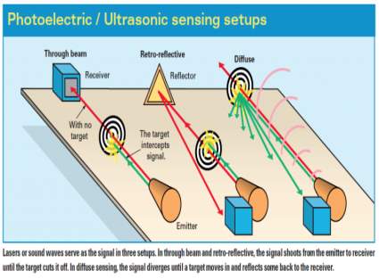
Fig 5.1
photoelectric sensors operate under similar principles. Identifying their output is thus made easy; darkon and light-on classifications refer to light reception and sensor output activity. If output is produced when no light is received, the sensor is dark-on. Output from light received, and it’s light-on. Either way, deciding on light-on or dark-on prior to purchasing is required unless the sensor is user adjustable. (In that case, output style can be specified during installation by flipping a switch or wiring the sensor accordingly.)
Through-beam
The most reliable photoelectric sensing is with through-beam sensors. Separated from the receiver by a separate housing, the emitter provides a constant beam of light; detection occurs when an object passing between the two breaks the beam. Despite its reliability, through-beam is the least popular photoelectric setup. The purchase, installation, and alignmentof the emitter and receiver in two opposing locations, which may be quite a distance apart, are costly and laborious With newly developed designs, through-beam photoelectric sensors typically offer the longest sensing distance of photoelectric sensors — 25 m and over is now commonplace. New laser diode emitter models can transmit a well-collimated beam 60 m for increased accuracy and detection. At these distances, some through-beam laser sensors are capable of detecting an object the size of a fly; at close range, that becomes 0.01 mm. But while these laser sensors increase precision, response speed is the same as with non-laser sensors — typically around 500 Hz.
One ability unique to throughbeam photoelectric sensors is effective sensing in the presence of thick airborne contaminants. If pollutants build up directly on the emitter or receiver, there is a higher probability of false triggering. However, some manufacturers now incorporate alarm outputs into the sensor’s circuitry that monitor the amount of light hitting the receiver. If detected light decreases to a specified level without a target in place, the sensor sends a warning by means of a builtin LED or output wire.
Through-beam photoelectric sensors have commercial and industrial applications. At home, for example, they detect obstructions in the path of garage doors; the sensors have saved many a bicycle and car from being smashed. Objects on industrial conveyors, on the other hand, can be detected anywhere between the emitter and receiver, as long as there are gaps between the monitored objects, and sensor light does not “burn through” them. (Burnthrough might happen with thin or lightly colored objects that allow emitted light to pass through to the receiver.)
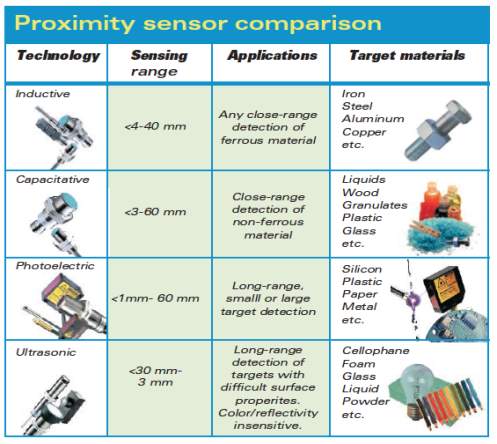
Fig 5.2
Retro-reflective
Retro-reflective sensors have the next longest photoelectric sensing distance, with some units capable of monitoring ranges up to 10 m. Operating similar to through-beam sensors without reaching the same sensing distances, output occurs when a constant beam is broken. But instead of separate housings for emitter and receiver, both are located in the same housing, facing the same direction. The emitter produces a laser, infrared, or visible light beam and projects it towards a specially designed reflector, which then deflects the beam back to the receiver. Detection occurs when the light path is broken or otherwise disturbed.
One reason for using a retro-reflective sensor over a through-beam sensor is for the convenience of one wiring location; the opposing side only requires reflector mounting.
This results in big cost savings in both parts and time. However, very shiny or reflective objects like mirrors, cans, and plastic-wrapped juice boxes create a challenge for retro-reflective photoelectric sensors. These targets sometimes reflect enough light to trick the receiver into thinking the beam was not interrupted, causing erroneous outputs.
Some manufacturers have addressed this problem with polarization filtering, which allows detection of light only from specially designed reflectors … and not erroneous target reflections.
Diffuse
As in retro-intelligent sensors, diffuse sensor producers and collectors are situated in a similar lodging. However, the objective goes about as the reflector, with the goal that recognition is of light reflected off the aggravation protest. The producer conveys a light emission (frequently a beat infrared, obvious red, or laser) that diffuses every which way, filling a discovery range. The objective then enters the territory and redirects some portion of the shaft back to the collector. Discovery happens and yield is turned on or off (contingent on whether the sensor is light-on or dull on) when adequate light falls on the beneficiary.
Diffuse sensors can be found on open washroom sinks, where they control programmed spigots. Hands set under the shower head go about as reflector, activating (for this situation) the opening of a water valve. Since the objective is the reflector, diffuse photoelectric sensors are regularly helpless before target material and surface properties; a non-intelligent target, for example, matte-dark paper will have an altogether diminished detecting range when contrasted with a splendid white target. However, what appears a disadvantage ‘at first glance’ can really be helpful.
Since diffuse sensors are fairly shading needy, certain renditions are reasonable for recognizing dim and light focuses in applications that require sorting or quality control by difference. With just the sensor itself to mount, diffuse sensor establishment is generally less difficult than with through-pillar and retro-intelligent sorts.
Detecting separation deviation and false triggers brought about by intelligent foundations prompted the advancement of diffuse sensors that concentration; they “see” targets and disregard foundation. There are two routes in which this is accomplished; the first and most normal is through settled field innovation. The producer conveys a light emission, much the same as a standard diffuse photoelectric sensor, however for two recipients.
One is centered around the coveted detecting sweet spot, and the other on the long-go foundation. A comparator then decides if the long-run beneficiary is identifying light of higher force than what is being getting the engaged recipient. Assuming this is the case, the yield remains off. Just when centered recipient light force is higher will a yield be created.
The second centering strategy makes it a stride advance, utilizing a variety of recipients with a movable detecting separation. The gadget utilizes a potentiometer to electrically modify the detecting range. Such sensors work best at their preset sweet spot. Taking into account little part acknowledgment, they likewise give higher resiliences in target territory cutoff determinations and enhanced colorsensing capacities. Be that as it may, target surface qualities, for example, polish, can create shifted comes about. What’s more, profoundly intelligent protests outside the detecting territory have a tendency to send enough light back to the recipients for a yield, particularly when the collectors are electrically balanced. To battle these confinements, some sensor producers built up an innovation known as genuine foundation concealment by triangulation.
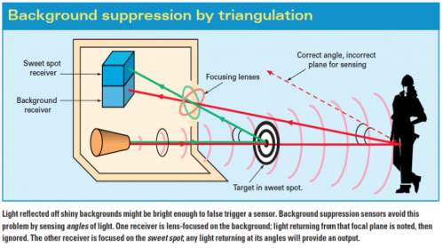
Fig 5.3
A true background suppression sensor emits a beam of light exactly like a standard, fixed-field diffuse sensor. But instead of detecting light intensity, background suppression units rely completely on the angle at which the beam returns to the sensor.
To accomplish this, background suppression sensors use two (or more) fixed receivers accompanied by a focusing lens. The angle of received light is mechanically adjusted, allowing for a steep cutoff between target and background … sometimes as small as 0.1 mm. This is a more stable method when reflective backgrounds are present, or when target color variations are an issue; reflectivity and color affect the intensity of reflected light, but not the angles of refraction used by triangulation- based background suppression photoelectric sensors.
5.1.3 APPLICATIONS
- Parking sensors, systems mounted on car bumpers that sense distance to nearby cars for parking
- Ground proximity warning system for aviation safety
- Vibration measurements of rotating shafts in machinery
- Top deadcentre (TDC)/camshaft sensor in reciprocating engines.
- Sheet break sensing in paper machine.
- Anti-aircraft warfare
- Roller coasters
- Conveyor systems
- Beverage and food can making lines
- Improvised Explosive Devices or IEDs
- Mobile devices
- Touch screens that come in close proximity to the face[
- Attenuating radio power in close proximity to the body, in order to reduce radiation exposure[
- 3D Touch will come true with the aid of proximity sensing elements.
- Automatic faucets
5.2 IC-7812
DESCRIPTION
The LM78XX series of three terminal regulators is available with several fixed output voltages making them useful in a wide range of applications. One of these is local on card regulation, eliminating the distribution problems associated with single point regulation. The voltages available allow these regulators to be used in logic systems, instrumenta-tion, HiFi, and other solid state electronic equipment. Al-though designed primarily as fixed voltage regulators these devices can be used with external components to obtain ad-justable voltages and currents.
The LM78XX series is available in an aluminum TO-3 pack-age which will allow over 1.0A load current if adequate heat sinking is provided. Current limiting is included to limit the peak output current to a safe value. Safe area protection for the output transistor is provided to limit internal power dissi-pation. If internal power dissipation becomes too high for the heat sinking provided, the thermal shutdown circuit takes over preventing the IC from overheating.
Considerable effort was expanded to make the LM78XX se-ries of regulators easy to use and minimize the number of external components. It is not necessary to bypass the output, although this does improve transient response. Input by-passing is needed only if the regulator is located far from the filter capacitor of the power supply.
For output voltage other than 5V, 12V and 15V the LM117 series provides an output voltage range from 1.2V to 57V.
Features
- Output current in excess of 1A
- Internal thermal overload protection
- No external components required
- Output transistor safe area protection
- Internal short circuit current limit
- Available in the aluminum TO-3 package
Voltage Range
LM7805C 5V
LM7812C 12V
LM7815C 15V
7812 is a famous IC which is being widely used in 12V voltage regulator circuits. Truly speaking it is a complete standalone voltage regulator. We only need to use two capacitors, one on the input and second one on the output of 7812 in order to achieve clean voltage output and even these capacitors are optional to use. To achieve 12V 1A current, 7812 should be mounted on a good heatsink plate. Thanks to the transistor like shape of 7812 which makes it easy to mount on a heatsink plate. 7812 has built in over heat and short circuit protection which makes it a good choice for making power supplies.
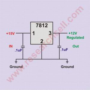
Fig 5.4 (7812 circuit diagram)
If you hold upside down (pins up) and the IC number is facing you then the left pin will be the voltage regulator output, the center pin will be ground and the right pin will be the voltage input pin. Under my experience, the maximum safe current you can get from one 7812 IC is 1A. If you need more power then there are a few ways to do so.
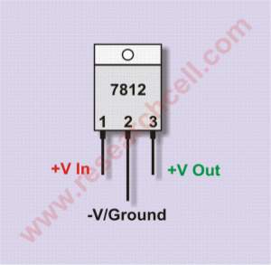
Fig 5.5
More than one 7812 can be used in parallel in order to achieve more than 1A current but output voltage of each 7812 can slightly vary resulting in unbalanced load on all of them. This can result in load balancing issues and can damage the IC carrying most current. However there is a way to overcome this problem. I have given bellow a schematic diagram in which two 7812 ICs are attached together and both of them are carrying almost equal load. At least the current difference is not too much to damage any IC.
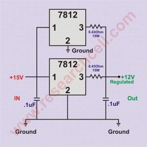
Fig 5.6 7812 in parallel circuit diagram
This parallel 7812 circuit will provide 12V and approximately 2A current. You can increase number of 7812 but each additional 7812 will require a resistor on its output.
6.1 PROGRAM
Controlling barrier and roadblocks using sensors which sense the incoming train and vehicles and sends a signal to PLC.
The PLC in return sends a signal to barrier and roadblocks. Once the train passes, the barrier and roadblocks retrieve back, and the passage is clear for vehicles and pedestrians to cross. PLC’s are used because they are very flexible, cost effective, space efficient, reduces complexity and minimizes errorsIn this project to lift the railway crossing gate D.C motor.
Gear and belt drive arrangement is used. The relay at two points on the either side of railway crossing gate is used as shown in fig. The relay will complete the circuit when railway will pass through if hence at that first time when rail will be near the gate, the gate will be closed and similarly when the rail will pass through the another relay which is mounted on the other side of gate, the relay will get operated completing the circuit.
Hence the motor will operate and with help of belt and gear drive, the gate will get opened. In this way the automatic operation of gate takes place. The gate which is unguarded, at such place the percentage of accidents is more.
Therefore to overcome this problem this system is capable. As it is fully automatic there is no chance of failure due to human mistake.
IMPLEMENTATION OF PROJECT
START


INTIALISE THE PLC
IS
SENSOR-1 DETECTS THE TRAIN
YES
RED LAMPS ON
MOTOR ROTATES FORWARD DIRECTION
GATES CLOSED
IF
SENSOR-2
DETECTS THE TRAIN
YES
GREEN LAMPS ON
MOTOR ROTATES IN REVERESE DIRECTION
GATES OPEN
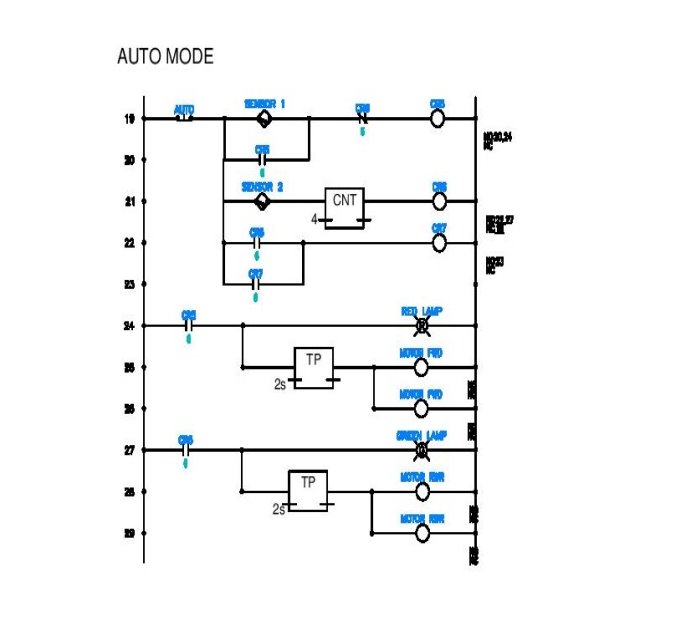
Fig 6.3
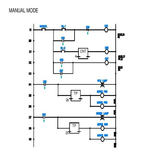
Fig 6.4
Conclusions and Future Scope
7.1 Conclusion
This paper aims at reducing the fatality and accident rate by controlling barrier and roadblocks using sensors which sense the incoming train and vehicles and sends a signal to PLC. The PLC in return sends a signal to barrier and roadblocks. Once the train passes, the barrier and roadblocks retrieve back, and the passage is clear for vehicles and pedestrians to cross.
PLC’s are used because they are very flexible, cost effective, space efficient, reduces complexity and minimizes errors..
Scope of project
- This project is developed in order to help the INDIAN RAILWAYS in making its present working system a better one, by eliminating some of the loopholes existing in it.
- Based on the responses and reports obtained as a result of the significant developmentin the working system of INDIAN RAILWAYS, this project can be further extendedto meet the demands according to situation
This can be further implemented to have control room to regulate the working of thesystem. Thus becomes the user friendliness.
This circuit can be expanded and used in a station with any number of platforms as per the usage.
- Additional modules can be added with out affecting the remaining modules.
This allows the flexibility and easy maintenance of the developed system.
This system consists of following features over manual system:
- There is no time lag to operate the device.
- Accuracy.
- Simulation is provided to reflect the present status of the system.
- End user can operate this without knowing about electronics
Reference Books
- J.B. GUPTA “Power systems” S.K. Kataria & Sons,2013
- P.C. Sen “Power Electronics” Tata McGraw-Hill Education, 1987
- Programmable Logic Controllers : Programming Methods and Applications (English) 1st Edition:by HACKWORTH
- Power System Relaying Book by Arun G. Phadke and Stanley H. Horowitz
- Principles of Electronics By V.K.Mehtha
- Photoelectric Sensors and Controls: Selection and Application, First Edition
IEEE PAPERS
- Krishna, ShashiYadav and Nidhi, “Automatic Railway Gate Control Using Microcontroller”, Oriental Journal Of Computer Science & Technology, Vol.6, No.4, December 2013.
- Ahmed Salih Mahdi. Al-Zuhairi,“Automatic Railway Gate and Crossing Control based Sensors &Microcontroller ”, IN International Journal of Computer Trends and Technology (IJCTT) – Volume 4 Issue 7–July 2013
- Bolton, w., Programmable Logic Controllers: An Introduction, Butterworth-Heine-mann, 1997.
- ] J. Banuchandar, V. Kaliraj, P. Balasubramanian, S. Deepa, N. Thamilarasi,“ Automated Unmanned Railway Level Crossing System”, in International Journal of Modern Engineering Research.
Cite This Work
To export a reference to this article please select a referencing stye below:
Related Services
View allRelated Content
All TagsContent relating to: "Transportation"
Transportation refers to the process of goods, people or animals being moved from one place to another. There are multiple methods of transport, including train, boat, bus, plane, lorry, and more.
Related Articles
DMCA / Removal Request
If you are the original writer of this dissertation and no longer wish to have your work published on the UKDiss.com website then please:


