Practical Activity of Characterizing a Battery
Info: 5350 words (21 pages) Dissertation
Published: 10th Dec 2019
Tagged: Electronics
Introduction
- To critically discuss the practical activity of characterizing a battery.
- To design an energy storage system for a premium plug-in vehicle to meet the given requirements.
Part 1: Characterization of a Battery
Lithium Ion batteries are subjected to mechanical and electrochemical degradation due to the demanding drive cycles of an automobile. Exploring the causes of degradation to ensure safe operation of a battery is essential for automotive manufacturers. Every battery is accompanied with a data sheet specifying various parameters of the battery. By characterizing a battery, it can be observed how the battery cell matches the manufacturer data sheet. The data sheet values are achievable for the battery in ideal conditions. However, the battery does not match the specifications to the dot in any given scenario. For automotive manufacturers to achieve optimum performance, need to evaluate the conditions in which the battery will operate. Following which, they can source the best performing battery for their requirements. One of the functions of the BMS is to prevent or reduce the degradation occurring during the life cycle of the battery. By understanding the process of degradation of the battery in the lab, it is possible to design the BMS to prevent the degradation from taking place and also keep a track of the capacity fade and power fade that occurs during the battery use(Uddin et al., 2016). The following tests mentioned below were undertaken during the practical activity week.
Capacity test at different C-rates
Capacity test is used to characterize a battery based on its capacity when discharged at different C-rates and to calculate the efficiency. The capacity is a measure of current with respect to time. In this test, three identical batteries were taken at the maximum SOC at 4.15V. They were discharged at different C-rates (2C, 3C and 4C) to 2.5V using CC-CV discharge and the parameters were noted.
| Capacity(Ah) | Energy(Wh) | Temperature(C) | |
| 2C | 3.10 | 10.19 | 47.5 |
| 3C | 3.08 | 9.99 | 65.0 |
| 4C | 3.05 | 9.63 | 76.0 |
Figure 1: Battery discharge at different C-rates (Source: Practical results)
From the results obtained, the capacity and energy of the battery are observed to reduce as battery is discharged at high C-rates. However, the temperature of the battery increased with a larger variance. In current day EV’s, during acceleration events, the battery is discharged at high C-rates and automotive manufacturers need to identify the temperatures variation of the batteries during their operation. To maintain the optimum operating temperature, cooling systems need to be considered in the design. This is essential for high performance vehicles, where the battery is discharged at high C-rate for short intervals. Knowing the rise in temperature, the operation of the battery is maintained in a safe zone. The BMS can be optimised using the results from this test to maintain stable battery temperatures.(Mulder et al., 2011)
The power capability of a battery can be characterised by observing the change in voltage, by applying a load current. In this test, the change in voltage is noted and the internal resistance is calculated using Ohms law by applying a timed discharge current pulse. A 10sec pulse is an accepted standard for the pulse power test. This test allows to measure the resistance based on different SoC and temperature of the battery.(Waag, Käbitz and Sauer, 2013)
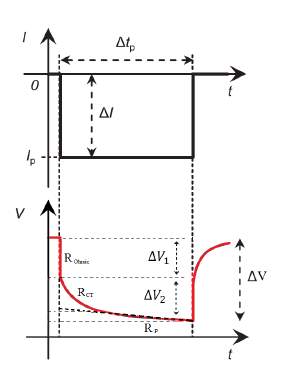
Figure 2:Voltage response of battery to current pulses (Waag, Käbitz and Sauer, 2013)
The pulse power test was performed on batteries, which were specified to have an internal resistance less than 35mΩ in the manufacturer data sheet. The table below shows the results obtained by testing the battery at different levels of SOC.
| 20% SoC | 50% SoC | 80% SoC | |
| Ohmic Resistance | 43mΩ | 39mΩ | 39.9mΩ |
| Total Resistance | 87mΩ | 48mΩ | 48.5mΩ |
Figure 3: Results of pulse power test (Source: Practical results)
The test was performed under three different levels of SoC. In all the three conditions, the internal resistance was well over the specified 35mΩ. It was observed that, at low SoC of the battery, the resistance of the battery drastically increases, reducing performance and causing heat build-up.
From the test conducted in the lab, it was observed that the voltage drop is not constant for the whole course of the test. During the start, there is a sudden drop in voltage, indicating the pure ohmic resistance of the battery. After which, the voltage change relating to charge transfer takes place followed by further voltage drop due to diffusion process in lithium leading to polarization. In automotive applications, the sum of pure ohmic resistance and polarization resistance is an indication of the battery performance. The results of this test can be used to track the change of internal resistance with ageing and estimate the optimal range of usable SoC in a battery. The vehicles are designed to be driven under different driving conditions and hence these tests provide an insight to the manufacturer on the variation in the internal resistance of the battery based on different levels of SoC, which can be implemented in the design of the BMS. This test employs a DC signal, therefore cannot measure capacitance and inductance directly. To fully characterize the battery, many current pulses with varying amplitude would be required, making the test time consuming.(Marracci et al., 2015)
Electrochemical Impedance Spectroscopy (EIS)
As discussed earlier, the pulse power test can only measure resistance due to the application of a DC signal. To fully characterize a battery, other methods can be combined to give a better result. In EIS technique, an electronic model is used to represent the electro-chemical properties of the battery. EIS technique has been proposed by (Vetter et al., 2005) as a fast, non-destructive and reliable technique, able to identify the actual origin of cell degradation processes and bring some ageing effects in light. In EIS technique, the impedance is measured by applying a single-frequency voltage/current to the setup to measure the phase and amplitude of the output at that frequency. The impedance is measured as a function of frequency in the range of 1 mHz to 1 MHz (Barsoukov and Macdonald, 2005). The EIS results are displayed using a nyquist plot with x-axis representing real-axis and y-axis representing imaginary-axis. Nyquist plot is used due to ease in observation of the ohmic resistance.
Due to the analogue nature of the reactions taking place in the battery, ECM of the lithium ion battery can be generated using the results from EIS as shown in figure 1. The ECM is made up of resistors, capacitors and inductors. The ECM design depends on the characteristics of the battery (Westerhoff et al., 2016). The ECM is plotted to match the waveform of the nyquist plot.
The nyquist plot consists of three frequency ranges, the high frequency region displays the inductive behaviour due to the SEI layer formation at the electrode-electrolyte interface, which causes capacity fade and increases resistance. The mid frequency region is mainly the charge transfer region showing the number of electrochemical reactions taking place and the low frequency region shows diffusion, which is represented by Warburg impedance.
The resistance is used to indicate power fade, which in turn is the indication of the state of health of the battery. With the ECM, simulations are performed to measure the degrading factors in a battery using a mechanical model.
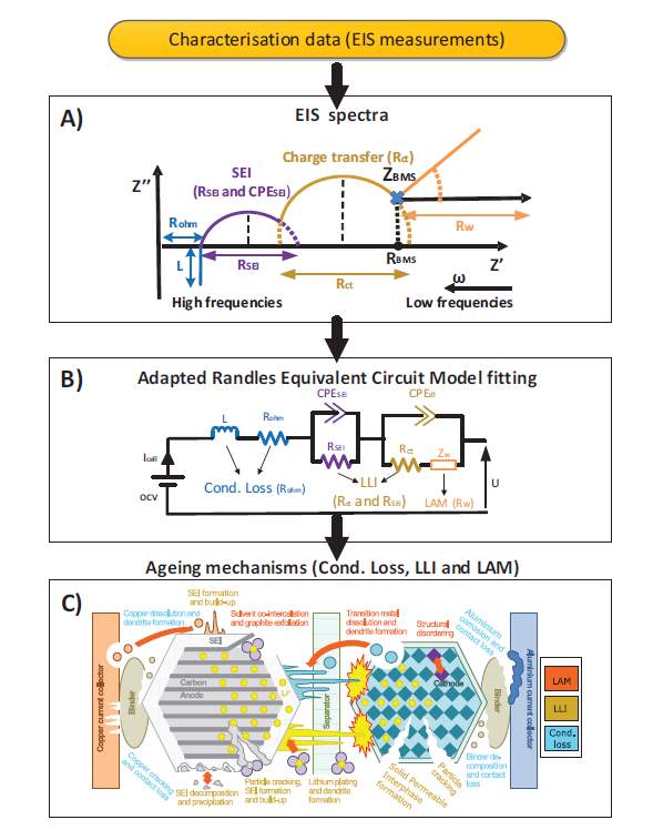
Figure 4: Relationship between EIS spectrum, ECM and ageing mechanism (Pastor-Fernandez et al., 2016)
Most common and fundamental source of capacity fade and increased resistance in lithium ion batteries is due to SEI, which mainly takes place at the cathode. SEI formed in the first few cycles electrically stabilises the system. It protects the graphite from decomposition by only allowing the flow of lithium ions. Over time, the SEI continues growing unevenly, blocking the flow of lithium ions, increasing resistance, leading to capacity fade.(Uddin et al., 2016). The capacity fade can be overcome by developing protection mechanisms for the anode material. Which will result in higher battery life cycle.(WMG, 2016)
The formation of SEI can be analysed using EIS, making EIS technique essential in characterising a battery.
Scope for further development
Even though lithium ion batteries are advanced and efficient, they can cause catastrophic damage under some conditions. By characterizing the battery independently, the safety and performance of the battery can be looked at and optimum approaches to improve or restrict the usage of the battery can be built in the BMS. The automotive manufacturers can utilize the characterization data to select the battery to meet their requirements.
Part 2: Design of energy storage system
Electric car were a concept ahead of its time, during their launch in the 1900’s. According to the (U.S. Dept. of Energy, 2014), one third of all vehicles on the road were electric vehicle. They were associated with refinement and zero emissions, mainly used by urban residents due to their short driving range. The low driving range due to the limited energy storage system technology was one of the main reasons that led the ICE vehicles to dominate. After more than a century, the automobile industry is considering electrification of the automobiles due to environmental concerns and new legislations. There have been advances in electronics and energy storage system, which has helped bridge the gap between the EV and ICE market.
The premium customers expect the EV to perform equal to, if not outperform the ICE counterparts without having to compromise on driving range. Optimum ESS design is essential, as it plays an important role in the design, efficiency and high performance of electric vehicles, especially in premium vehicles. In this report, the available ESS’s are critically evaluated and a design for an optimum ESS for a high performance premium EV is proposed. Along with the design of the ESS, the various design challenges are considered and solutions are discussed to challenges identified.
To present an outline design of an energy storage system for a premium plug-in electric vehicle. The ESS requirements are:
- 230 Wh/mile test cycle energy.
- 120 miles test cycle range
- 400 kW power output for 10 seconds.
- 150 kW power output for 30 seconds.
- 750 to 850 V DC at the ESS output (Traction inverter supply).
- 8-year design life.
In this section, the ESS requirements are analysed and necessary parameters are calculated based on certain assumptions mentioned.
- Test cycle energy requirements
120-mile test cycle range at 230 Wh/mile is required. The total energy requirement for the complete test cycle is:
120 miles*230Whmile=27.6 kWh#10.1
- 400 kW power output for 10 seconds
The energy required for one 10 second power pulse is:400 kW*103600=1.2 kWh#(10.2)
As the design involves a premium EV, the ESS is designed to provide three consecutive power pulses to ensure there is sufficient energy in the ESS for three high acceleration events. Hence the total energy required is:
1.2 kWh*3=3.6 kWh#10.3
- 150 kW power output for 30 seconds
The energy required for one 30-second power pulse is:
150 kW*303600=1.25 kWh#10.4
The ESS is designed to provide six consecutive power pulses to ensure there is sufficient energy for six 150 kW power events. Hence the total energy required is:
1.25 kWh*6=7.5 kWh#10.5
- 750 to 850 V DC at ESS output
At present, the VLSI devices available have a maximum operating voltage of 450V(Mueller and Heinrich, 2013). A substantial effort is required to develop devices operating at 800V. Hence, the ESS is designed to be under 450V with a DC-DC converter designed to step up the voltage to 800V DC.
- 8 year design life
A study conducted by the UK government department of transport claims that in the UK, vehicles travel an average of 8000 miles a year (NTS05, 2014). This indicates that the weekly usage for most drivers would be around 150 miles. An assumption is made that ideally the EV will be charged twice in a week based on the 120-mile test cycle range. Therefore, for 8 years, the total charge-discharge cycles would be:
2*52 weeks*8 years=832 Cyles#10.6
Even though lithium ions are claimed to have more than 1000 cycles at 100% DoD, the usable SoC of the battery is limited to increase the battery life cycle.
The electrical load on a vehicle can be divided into static and dynamic load. The static load represents the continuous power requirement, requiring a high-energy source. The dynamic load consists of short intervals of high performance requirements, requiring a power source (Gao et al., 2003). By combining the two ESS, a hybrid ESS can be created to meet both the energy and power requirements.
Batteries have been around since the mid-1800. Lead acid batteries were the first rechargeable batteries manufactured. They had low energy density and low cycle life making them unfavourable for modern automotive requirements. Ni-Cd/Ni-MH batteries have been used in automotive applications due to their high cycle life but are unsuitable for EV applications due to their low energy density.
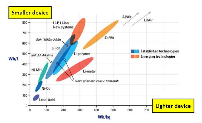
Figure 5: Specific energy versus specific power of electro chemical batteries (Source: Class Notes)
Li-Ion batteries have high energy to weight ratio making them ideal for automotive applications due to weight constraints in vehicle design (Vazquez et al., 2010). Due to their high energy density, lithium-ion batteries are selected as the high energy ESS in this design.
There are various ESS’s available to meet the high power requirement. From Eq. 10.3 and Eq. 10.5, the power requirements are 150 kW and 400 kW with total energy of 11.1 kWh required. The high power ESS is designed to meet the complete power requirements of 150 kW and 400 kW. This is to ensure that the driving range is not reduced. Based on these requirements, the different high power ESS’s are evaluated below.
Even through Li-Ion batteries are primarily used for high energy density in EV’s; there are different chemical combinations through which a high power density can be achieved. These cells, which are designed for high power applications are able to operate at high temperature and are capable of handling high C-rate discharge.
An excellent example for this is A123 systems 26650 high performance cell, which has a capacity of 2500mAh at around 3.3V nominal cell voltage. The cell uses Nano phosphate LiFePO4 chemistry. This cell is designed keeping performance in mind and allows for a continuous maximum current discharge of 50 Amps, which is around 20C discharge rate and a pulse discharge of 120 Amps at 48C for 10 seconds.

Figure 6: A123 Systems ANR26650M1-B-A battery data sheet (A123 Systems, 2017)
From Eq. 10.3 and Eq. 10.5, the total energy required for high power is 11.1 kWh. This value is approximated to 12 kWh for calculation purpose. The A123 battery claims 2000 life cycle at 100% DOD. As a precaution, the usable SoC is limited to 80%, requiring a 15 kWh battery capacity.
The cell is discharged at 32A (12.5C), giving out 150kW to meet the 30 second power requirement. During the 10 second pulse requirement, the cell is discharged at 80amp A (32C), giving out 400kW power output. The battery pack weighs 136 kg. Under normal driving conditions, it is possible to utilize this battery pack with the primary battery to provide additional driving range of about 55 miles.
Electro-chemical capacitors with patented names such as super capacitor or ultra-capacitor have high power density and are able to operate at high C-rate. They benefit from very high cycle life with capability of 100 DoD with no loss in capacity. Super capacitors have a long service life. However, they suffer from very low energy density and a complex control system is required to maintain optimum storage and recovery of energy, as the cells can be damaged due to overheating, hence requiring thermal management (Gao et al., 2003).
Maxwell technologies has a BCAP0310 super capacitor suitable for automotive applications (Maxwell Technologies, 2017). It is specified with a power density of 6.6kW/kg and energy density of 5.2Wh/kg. To meet the 400 kW power requirement, the pack weighs about 60 kg. However, to meet the energy requirement of 11.1 kW, the pack would weigh around 2000kg. One possible solution to this is to design the super capacitor for the power requirement and use the battery as an energy source to charge the super capacitor. This would require upsizing of the battery, which is undesirable as frequent discharge from the battery, would cause degradation of the battery. Super capacitors are ideal for KERS applications, where there are frequent stops through which regenerative braking energy can be stored in the super capacitor and then used to boost the vehicle.
Flywheels have been around since the 11th century. Flywheel stores energy in mechanical form in a rotatory mass. For automotive application high-speed flywheels have high power density, high cycle life and offer excellent efficiency (Hedlund et al., 2015). Flywheels have gained popularity with the advances in power electronics and their applications in motorsport. An ultra-high speed flywheel can rotate up to 50000 RPM with an idle RPM of around 18000 RPM and can be charged and discharged rapidly. A well-designed flywheel can last over 20 years. Flywheels can be categorised based on their power transfer methods, mechanical and electro mechanical. A mechanical flywheel uses a CVT gearbox to deliver the power, this is ideal for vehicles with an ICE. Electro-mechanical flywheels store energy in mechanical form but the output is electric energy, which is transferred to the traction motor of an electric vehicle. (Eshani et al., 2010)
The GKN MK10 flywheel, which is in use in racing applications (GKN FESS, 2017), has a peak power of 120 kW weighing at 120 kg, with a usable energy of 1 kWh, requiring a 360 kg system only enough to meet the power requirement. The weight will increase considerably to meet the energy requirement. Flywheel is an excellent choice for KERS applications such as Formula 1 and City busses where energy from frequent braking needs to be recovered.
One of the main disadvantages of the flywheel is that a constant power source is required to keep it spinning at idle RPM, requiring energy from the primary battery in an EV. The flywheel being a high-speed rotating mechanical device has lot of safety and reliability aspects involved in the design. (Dhand and Pullen, 2015)
In premium vehicles, the primary battery would need to be oversized to accommodate the power required to keep the flywheel spinning and the dependency on regenerative braking is undesirable. Unlike super capacitors and batteries, the flywheel is a single unit and has to be well placed for weight distribution.
Hydraulic ESS use hydraulic pump connected to the transmission. Gas is compressed using hydraulic oil, which is stored in a pressurised cylinder. The pressure is then released to supply the power to the wheels when required. The hydraulic ESS benefits from high power density. However, has several safety concerns associated with the pressurised tanks, thermal management and mechanical fatigue making it unsuitable for the design proposed in this paper.
Due to the complexity and low energy to weight ratio in incorporating flywheels, super capacitors and hydraulic ESS, A123 systems ANR2660MI high performance battery is selected as high power source. In addition to fulfilling the high power requirement, the high power batteries add to the driving range while driving normally as they do not need to rely on regenerative braking or energy from primary battery to keep them operating as they can store sufficient energy to meet the complete drive cycle power requirement.
There are mainly three cell formats currently available for batteries. A comparison table for these cell formats is shown below.
| Cylindrical Cell | Prismatic Cell | Pouch Cell |
| High battery energy density | Lower battery energy density | Lower battery energy density |
| High mechanical stability | Lower mechanical stability | No mechanical structure (Retaining material required) |
| Inefficient space utilization due to waste of space | Efficient space utilization
(Made to fit) |
Efficient space utilization
(Made to fit) |
| Low manufacturing cost | Higher manufacturing cost | Higher manufacturing cost |
| Venting mechanism present | No venting mechanism | No venting mechanism |
Figure 7: Comparison of different cell formats (Andrea, 2010)
A cylindrical cell is encased in a metal cylinder, making it mechanically stable. There is no additional mechanical structure required, as the battery is capable of withstanding high internal pressures due to the venting mechanism present. They have lower manufacturing cost and are readily available to meet any required specification. Hence, cylindrical cells are considered for the purpose of this design.(Andrea, 2010)
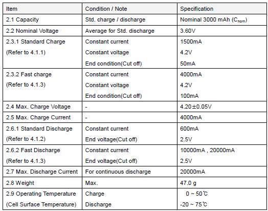
Figure 8: LG 18650 HG2 battery data sheet (Batteries18650, 2017)
From the Eq. 10.1, a total energy of 27.6 kWh is necessary to complete the drive cycle. In this design proposal, a LG 18650 HG2battery is considered with 3Ah capacity. It has a nominal cell voltage of 3.6V and supports both CC and CV charging methods. The specifications are in line with other 18650 batteries in the market. LG claims 1000 cycles at 100% DOD for HG2. To extend the life cycle of the battery pack, the SoC usage is limited to 80%, requiring a 35 kWh battery. The usable SoC of the battery is kept at around 10 to 90%, to ensure the battery can still perform and provide the same energy as the beginning of life at EoL and exceed the 8 years minimum design requirement.
When designing a battery pack, there is compromise between the voltage and current. To get the pack voltage, cells need to be grouped in series and to obtain the pack capacity; the cells need to be grouped in parallel. Cells are split into groups, as having several in a single series link creates a single break point. Cells in series are similar to a metal chain, where the strength is depending on the weakest link.
High energy density battery pack
A pack voltage of 360 volts is assumed, requiring 100 cells in series considering the cell voltage of 3.6 volts. Hence the energy per string in series is:
100*3*3.6=1.08 kWh#12.1
A continuous power output of 35kW is required from the battery pack. Using ohms law, we have the current required from the battery pack as:
35 kW360 V=98 Amps#12.2
The total number of strings required in parallel to meet the required capacity is:
35 kWh1.08 kWh=33#12.3
Hence, 33 strings are required in parallel. The pack design consists of 3300 cells in total divided into of 20 modules in series. Each module is made up of 5 groups in series consisting of 33 cells in a parallel group. Each cell weighs 44 grams and a total of 3300 cells are used, getting the pack weight to 160 kg.
High power density battery pack
A pack voltage of 330 V is assumed, requiring 100 cells in series considering the cell voltage of 3.3 V. The energy available in each series string is
100*2.5*3.3=0.825 kWh#12.4
To supply the 10 second 400kW power output, the current required from the pack can be calculated using ohms law
400 kW330 V=1212 Amps#12.5
The total number of strings required in parallel to meet the required capacity is
15 kWh0.825 kWh=18#12.6
Hence, 18 strings are required in parallel. The pack contains 1800 cells in total consisting of 20 modules in series. Each module is made up of 5 groups in series consisting of 16 cells in a parallel group. Each cell weighs 76 grams with total of 1800 cells used, getting the battery pack weight to 136 kg.
In this section, the pack arrangement for the hybrid ESS is designed. Combining both the battery packs, the total weight of the hybrid ESS is calculated to be 296 kg.
In automotive applications, a voltage above 60V DC is classified as high voltage according to UN-ECE Regulation 100. The DC source voltage is an essential design parameter for every EV. The DC source can be a HV battery, super capacitor, flywheel etc. The 18650 battery proposed in this design has a nominal voltage of 3.6V and end voltage of 2.5V. This variation is quite high when the complete battery back voltage of 360V is considered, leading to several limitations for the powertrain, BMS and control system design. At present, the VLSI devices available have a maximum operating voltage of 450V. A substantial effort is required to develop devices operating at 800V and numerous redundancies would be necessary. By using a HV DC-DC converter, the BUS voltage can be fixed independently of the varying ESS voltage to give precise voltage output.(Mueller and Heinrich, 2013)
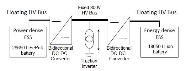 Figure 9: Dual source floating HV bus architecture (Source: Class notes)
As per the requirements, the output of the ESS needs to be in the range of 750V to 850V DC. The design proposal involves two sources of energy operating at a nominal voltage of 360V and 330V. A Dual bidirectional DC-DC converter DC bus proposal is presented in this design for the two ESS’s. This is done to ensure that the traction inverter voltage is fixed, regardless of the operating voltage of the ESS. The BMS is responsible to direct the flow of power between the two ESS’s based on the power requirements.
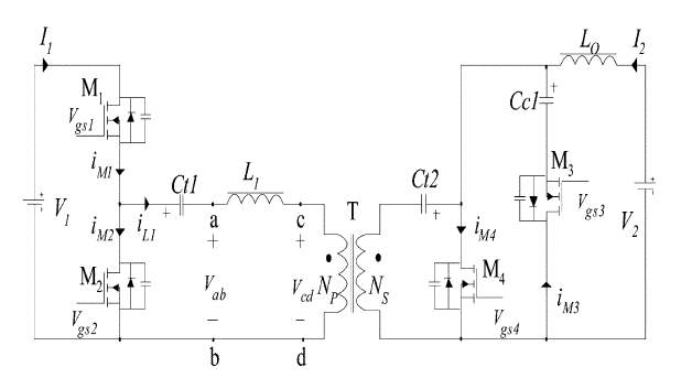
Figure 10: Bidirectional Phase Shift DC-DC Converter (Xu, Zhao and Fan, 2004)
There are numerous DC-DC converters available in the market. PWM is used in DC-DC converters operating as an electrical transformer between input voltage Vab and output Vcd. In PWM, the duty cycle is varied to control the ON to OFF ratio, thus switching the MOSFET on and off. The huge limitation while selecting the DC-DC converter is the efficiency, especially at high switching frequency there are high switching losses as shown in figure 11.
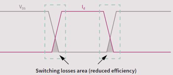
Figure 11: Switching losses (Infineon Technologies, 2017)
An excellent PWM plus phase-shift control bidirectional DC-DC converter is proposed in (Xu, Zhao and Fan, 2004) reducing current stress, conduction losses and switching losses. It was also found that the converter under plus phase shift control is able to achieve ZVS in large load variation.
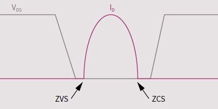
Figure 12: Soft switching using ZVS and ZCS (Infineon Technologies, 2017)
In ZVS, the voltage within the transistor is zero before switching occurs, reducing turn on switching losses. This process is also referred to as soft switching. (Infineon Technologies, 2017)
Cite This Work
To export a reference to this article please select a referencing stye below:
Related Services
View allRelated Content
All TagsContent relating to: "Electronics"
Electronics regards the science and technology involved in the development of electrical circuits and electronic devices and equipment that use them.
Related Articles
DMCA / Removal Request
If you are the original writer of this dissertation and no longer wish to have your work published on the UKDiss.com website then please:


