Clothes Drying Unit Using Heat Energy from Radiator
Info: 14296 words (57 pages) Dissertation
Published: 11th Dec 2019
Tagged: Energy
Contents
1.4 Summary of the Report Layout
2 Product Design Specifications
3.2 Detailed Design and Analysis
3.3 Design Embodiment and Evaluation
7.2 Appendix B Specification sheets
Currently tumble dryers populate the clothes drying market, with approximately 85% of the households in the USA owning one (32). Although tumble dryers are the fastest appliance to dry wet clothes, they have a considerably large operating cost in comparison with other drying appliances. On average the running cost of a tumble dryer per year costs £100 (33). On the opposite end of the scale, the clothes airer uses the ambient room temperature to dry the wet clothes. However the time frame in which the clothes are dried is considerably longer in comparison with the tumble dryer. To design a clothes drying unit which uses the emitted heat energy from a radiator to assist with the drying process. Currently on the market there is an opportunity to design a clothes drying unit, which can compete with drying time frame similar to the tumble dryer with a much lower operating cost. The design will be incorporated around the design and shape of a standard double-convection radiator. The emitted heat energy from the radiator will allow the moisture within the clothes to evaporate at a quicker rate, accelerating the drying time frame. Along with the assistance of the radiator’s heat energy, further assistance will be considered provided the source operates with a low energy consumption.
Keywords: Clothes, Drying, Radiator, Consumption, Moisture
Background
With approximately 64.1 million people currently living in the UK there is always a high demand for clothing. Recent studies stated that 800 billion items of clothing get purchased yearly worldwide. No matter the item of clothing they all have one thing in common, they all need to be washed. Laundry drying has a massive energy consumption. Based on a study from the USA, the electricity consumption for drying clothes is estimated as 71 terawatt hours per year, which accumulates to 9% of the electricity consumption for the USA [20]. Currently, clothes are washed either by a washing machine or are hand washed. Once the clothes get washed they need to be dried and depending on the item of clothing the drying time frame may be desirable. Problems begin to occur during the drying process. Current clothes drying processes with the primary function dedicated to drying are;
- Tumble Drier
- Clothes Airer
- Washing Line
Each of these drying clothes drying methods come with pros and cons. Tumble driers can effectively dry clothes within a desired time frame however, shrinkage of clothes occurs during the drying process and also its quite expensive to run.
A clothes airer is a free drying process with a support frame allowing the clothes to be dried naturally. However, the time frame in which the clothes are dried is considerably longer than that of the tumble drier. The washing line can be a useful clothes drying solution however its weather depending.
Due to the lack of alternatives to the clothes drying methods mentioned above, people resort to using radiators to dry wet clothes.
1 Introduction
Domestic radiators are a form of heat exchanger which transfers heat energy by convection and radiation. Radiators are the most popular central heating emitters in the UK. A radiator uses radiant energy to transfer heat to the air through electromagnetic waves, however the main heat contribution of a radiator is through convection. Radiators draws heat from water or steam to heat the surrounding area. Convection currents created allows the heat energy to disperse within the surrounding area. Radiators draw in cold air through the bottom of the radiator, heat the air causing it to rise and then release it into the surrounding area. Heating the air causes its particles to gain energy making them vibrate at a higher frequency making them move faster. As more air is drawn through the bottom and over the ‘fins’ of the radiator, atoms continue to vibrate faster and faster and thermal energy is created.
Folds on a radiator primarily made from a cast iron, maximise the surface area in contact with the air resulting allowing for a higher thermal transfer.
 A radiators primary function within a domestic household is to supply heat to the surrounding area depending on placement of the radiator. However due severe and unpredictable weather conditions especially here in the UK, particularly during the winter months’ people refer to using radiators to dry clothes as this weather neglects the washing line. During the winter months the rainfall can double compared with summer rainfall. The wettest place in the UK was recorded in Snowdonia, Wales where their average annual rainfall exceeded 3,000mm [1].
Figure 1- Average Winter rainfall distribution for 2015 in the UK
When clothes get dried on radiators heat energy gets dissipated through the clothes affecting the output heat efficacy of the radiator. As energy gets dissipated through the clothes, this increases the time frame in which it takes the room to reach the desired temperature.
Condensation a by-product of drying clothes indoors, occurs whenever water vapour meets cold surfaces and condenses to form dampness. Due to the increase of water moisture released into the air due to clothes being dried on radiators, this increases the rate and quantity of dampness. Drying clothes indoors on convection radiators can also be a serious health risk to those people occupying the same vicinity as the radiator. Currently in the UK, 5.4 million are receiving treatment for asthma and this drying method can be a serious health risk for people who suffer from underlying respiratory conditions. Dr Denning, who is professor of infectious disease in global health at The University of Manchester, stated that approximately 87% of people in the UK dry their clothes indoors in the winter [21].
Research has stated that one load of washing absorbs approximately 2 litres of water, which will evaporate into the surrounding atmosphere during the drying process [22]. The moisture within the wet clothes contains bacteria and fungi and when inhaled can cause coughing and other lung infections, affecting people more so who have underlying respiratory conditions.
Alternative clothes drying units are available such as the tumble drier and the clothes horse however these options as well come with drawbacks. Tumble driers can effectively dry clothes within a short time frame whoever shrinkage of clothes can occur during the drying process and it’s quite expensive, with a 35p per hour running cost. Clothes horses do not contribute to the actual drying of the clothes, however it maximises the surface area in contact with the air, allowing the ambient temperature of the room to dry the clothes.
The aim of this project is to design and manufacture a clothes drying unit whilst considering the issues with the current clothes drying methods.
1.1 Literature Review
Aslanturk et.al evaluated how by optimizing the geometry of a central heating radiator affected the heat transfer rate. The radiator problem is divided up into three-one dimensional fin problems then from this, the temperature distribution from the fins and the heat transfer rate from the radiator can be attained analytically [2]. For the analysis a number the following assumptions were made; considered it was steady state, temperature change across the thickness was neglected, temperature distribution in the radiator is one-dimensional, angular in the tube and axial in the fins. Convections fins, found in the majority of radiator designs, are designed to minimize the volume or mass for a given amount of heat dissipation and to maximize the heat dissipation for a given volume or mass.
The graphs below show in figure 2 temperature distribution for a set of given thermal and geometrical parameters [3].
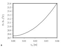
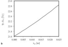
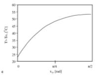
Figure2- shows the temperature distribution of the three radiator sections.
The optimization procedure can be conducted by locating the geometrical and thermal conditions that yield the total heat transfer rate. A graph of the heat transfer rate against tubular radius can be shown below in figure 3 [4].
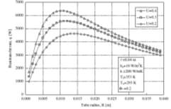
Fig. 3. Heat transfer rate versus radiator tube radius for the given volume fraction and inner fluid velocity.
Figure 3 above, clearly displays where the maximum heat transfer rate occurs in relation to the tube radius. The analysis showed that as the radiator volume fraction increases the maximum heat transfer and the optimum tube diameter also increases.
Beck and Grinsted et al. investigated the current design of domestic radiators and the different factors affecting heat transfer between radiators that contain high emissive sheets and convectional radiators with fins.
The purpose of fins used in radiators is to increase the surface area that’s in contact with the surrounding air enhancing heat transfer. However, these fins can be an expensive part of the design as they need to be fabricated and also dust gathers between the fins affecting the efficiency of the thermal output. A number of aspects can affect the output efficacy of a radiator. These are [11];
– If the height of the radiator from the ground was decreased and if the spacing from the wall was increased, then this would slightly increase the output of the radiator [5].
– Lowering the water flow rate through a radiator can reduce the heat output [6,7].
– The introduction of fins increases the convection heat transfer.
– Varying the connection positions will influence the performance. The most common installation being with both connectors at the bottom (BOE). However, introducing the flow at the top (TBOE) can improve the temperature distribution within the radiator and is used in the standard. Others are based on the radiation from the radiator.
- If the wall adjacent to the radiator has an insulated reflector, this can lower the heat loss through the wall by 70% [8]. However, this will reduce the heat output from the radiator [9], as the heated wall acts as another convection surface.
- (g) A metallic paint finish can reduce the radiant component of radiator heat outputs by up to 10% [10].
The experiment shown below was used to test the heat transfer between the inside surfaces of the radiators. Three different configurations were used with only the distance between the radiator panels and high emissive sheets being the variables. The experiment was run over several months allowing the effect of fouling on the heat transfer from the conventional radiator with internal fins to be measured. Whenever the operating conditions where varied, the power output was recorded. Neutral network analysis was used to make the results easier to interpret and reduce the discrepancies from the experiment [22].
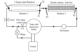
Figure 4 – shows a schematic diagram of the apparatus used within the experiment
The graph below of input temperature against power output was plotted from the results of the experiment [23].
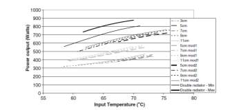
Figure 5 – Graph displaying the predicted heat output from the neutral network
Due to fouling, the heat output of the radiator reduced by 20% [24]. Cleaning of these fins is a difficult job due to their position alternatively panels would be easier kept clean. Results also showed minimal difference regards heat output whenever the spacing between the panels was altered concluding heat transfer is independent of the gap. The only exception to this is the solid grey circles which is a 5-cm gap with a single sheet in the middle where the heat transfer is up to 10% lower than that for a larger gap [13].
Tumble driers are the most popular domestic clothes drying unit currently available on the market. However, there is a possibility of material shrinkage during the drying process as well as its expensive operational cost. Manuel R. Conde investigated the energy consumption of a standard domestic tumble drier in laundries. They reported that that 0.5% of the total energy consumption of Switzerland is from laundry drying [14].
J. Deans investigated the modelling of the domestic tumble dryer. The experiment was completed to satisfy Australian/New Zealand Standard 2442 [15]. These standards stated that there is a mixed cotton load in the drum and that the wet clothes mass should be twice as much as the dry mass. For this investigation the tumble dryer had a drum volume of 0.08m3, clothes had a dry mass of 4.16kg, clothes had a wet weight of 8.318kg and the power input (heater and fan) was 4.16kWh. The graph below investigated the temperature (oC) against time (minutes) [26].
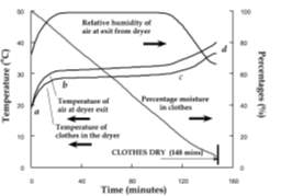
Figure 6 – shows the drying time against temperature and percentages
The drying process was considered complete when the rate of moisture removal from the clothes reached a critical value shown above in figure 5. At the end of each test, the exhaust air relative humidity reduces to an almost constant value which varies between 50% and 70% [16]. It was calculated that the tumble dryer required a total power input of 1.81 kW to dry a cotton load with a wet mass of 8.32kg to a dry mass of 4.16kg in 148minutes. 63% of the energy supplied was used for the drying processes, the rest of the energy was lost through the exterior cabinet walls and through heat loss through the exhaust air stream. Results from the test showed that the drying of the clothes within the drum is not homogeneous. The material type being dried, water content of the material and the packing density of the clothes affects the distribution of the clothes within the drum and the axial variation in temperature of the air, clothes and drum wall.
The performance tests showed that the distribution of the clothes within the dryer is affected by the mass and moisture content of the clothes. A large mass of clothes with a large moisture content within the rotating drum, causes a cohesive bundle to from at the base of the drum. This clothing formation, found in the early stages of the process, within the drum limits the drying process through conduction and evaporation via the outer layer of the bundle. Also the temperature air and drum tends to be higher than the outer surface temperature of the clothing in this formation. However, during the later stages of the drying process majority of the clothing will have partaken in the tumbling action.
A computer model was designed to concentrate on heat and mass flow rates within the drum of the tumble dryer. Also to highlight areas of the tumble dryer design that has the possibility of being improved. Sensitivity analysis was performed to shows that the factors affecting the drying time were the mass of the clothes and the power input. The specific energy consumption of the dryer is mainly influenced by the ambient air temperature and its relative humidity [17]. The analysis also shows that with increasing air mass flow rate and power input the consumption decreases. Results also showed that by increasing the air mass flow rate will lower the drum rate and therefore increase the evaporation rate. Also, the lower drum temperature means that less energy will be lost to other parts of the dryer and to the surrounding area improving the efficiency of the drying process. This analysis shows that by increasing the energy input this will reduce the drying time and the energy consumed during the drying process [18].
Results from this experiment found that lint, which accumulates from the drying cycle, reduces the air flow rate and increases the air temperature entering the drum. Results also showed that if the power input was increased then this would decrease the specific energy consumption and the drying time of the load within the drum. The performance test showed that 16% of the input energy gets emitted from the dryer as exhaust gases [25].
1.2 Data Analysis
Experiment to compare the drying rate of the same items of clothing dried within a tumble dryer and on an airer. For this experiment 10 T shirts, varying in size from x-small to large were initially weighed to understand their dry weight and then placed into a washing machine for a 30-minute mini wash. Next, the clothes got re-weighed to understand their wet weight prior to them undergoing the drying process.
1.2.1 Tumble Dryer
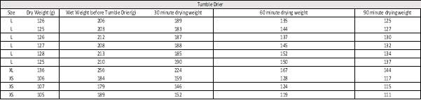 The wet clothes were then placed into the tumble dryer for 90 minutes and at every 30 minute intervals the clothes were weighed. The tumble drier operated at 2.8kWh, taking the average electricity tariff for the UK is 14p per kWh, the operating cost is £0.40.
Table 1 – below displays the wet and dry weights of the T-Shirts at each time interval when dried within the tumble drier.
1.2.2 Airer
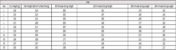 The wet clothes were then placed onto an airer for 240 minutes and at every 60-minute interval clothes were weighed. The airer was placed within a room with a temperature of approximately 22.6 OC and this was considered to be constant throughout the experiment.
Table 2 – below displays the wet and dry weights of the T-Shirts at each time interval when dried on the airer.
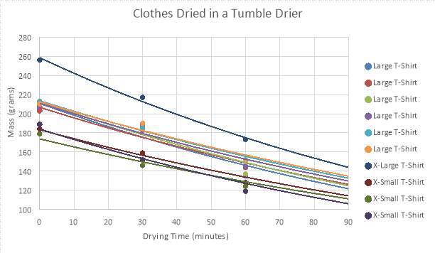
Graph 1: Shows the exponential relationship of mass (grams) against the drying time (minutes) for clothes dried in a tumble dryer
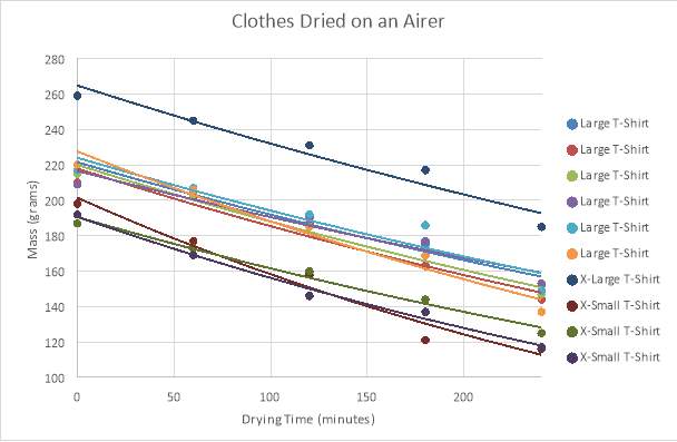
Graph 2 – Shows the exponential relationship of mass (grams) against the drying time (minutes) for clothes dried on an airer.
Mass Factor
Table below displays the values for the mass factors of the clothes dried within the tumble dryer and on the airer at each time interval. This provides better representation of the data as the variance in T-shirts size is neglected. From the mass factor against time graph the drying rate for each T-shirt can be calculated.
Mass Factor =
WW-DwDW
| (1) |
Where;
Ww = Wet Weight (g)
Dw = Dry Weight (g)
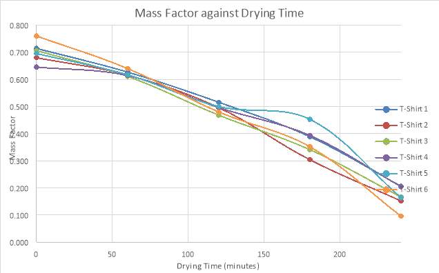
Table 3- below displays the mass factor for each T-shirt at the corresponding time interval within the tumble dryer.
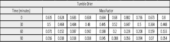
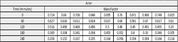
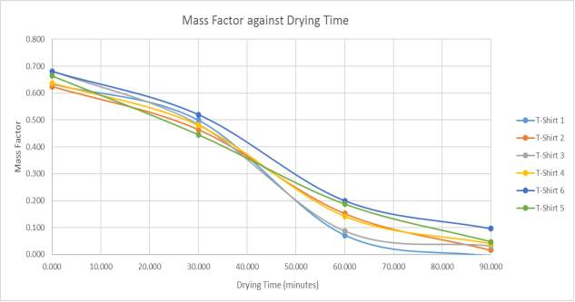
Table 4 – below displays the mass factor for each T-shirt at the corresponding time interval on the airer.
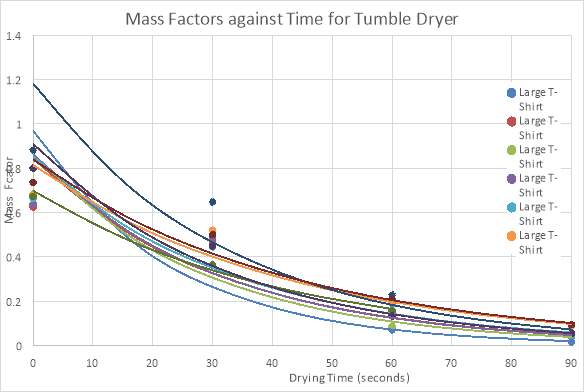
Graph 3 – Shows the exponential relationship of mass factor against drying time (minutes) for clothes dried in a tumble dryer
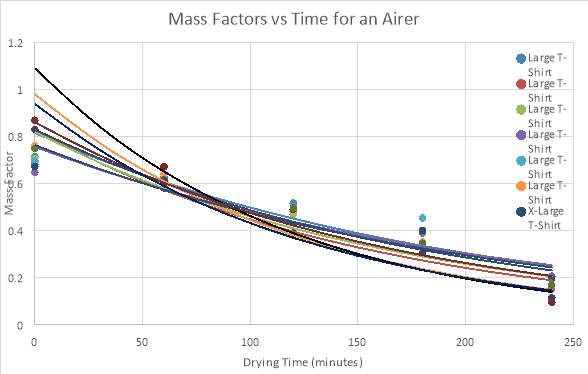
Graph 4 – Shows the exponential relationship of mass factor against drying time (minutes) for clothes dried on an airer.
Mass Factor as a Function of Time
Mf (t) = Mfo.
e-tτ (2)
Where;
- Mfo = Initial Mass Factor (t(m) =0)
- Mf(t) = Mass factor at time, t (m)
- T = Time (minutes)
- Ʈ = Time constant
For the analysis below, the 6 large t-shirts were selected to decrease the variance within the results. The mass factor for each t-shirt was obtained and was used to calculate the time constants and tau value for both drying processes.
Tumble Dryer
Table 5 – Mass Factor for T-shirts dried in a tumble dryer
From the values calculated above for Mfo and Tau, Ƭ the formula for mass equates to;
Mf (t) = 0.69
e-t47.5
- After 1 time constant (47.5 minutes) the mass of the clothing reached with 37% of the critical dry weight.
- After 2 time constants (95 minutes) the mass of the clothing reached within 13.7% of the critical dry weight.
- After 3 time constants (142.5 minutes) the mass of the clothing reached within 5% of the critical dry weight.
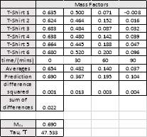
Airer
Table 6 – Mass Factor for T-shirts dried in a tumble dryer
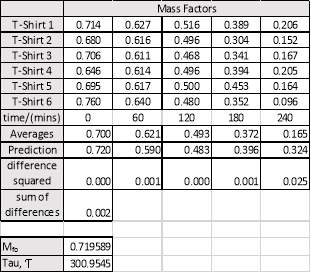
From the values calculated above for Mfo and Tau, Ƭ the formula for mass equates to;
Mf (t) = 0.72
e-t301
- After 1 time constant (301 minutes) the mass of the clothing reached with 37% of the critical dry weight.
- After 2 time constants (602 minutes) the mass of the clothing reached within 13.7% of the critical dry weight.
- After 3 time constants (903 minutes) the mass of the clothing reached within 5% of the critical dry weight.
The calculations show that it takes the tumble dryer 142.5 minutes to dry the clothes to within 5% of the critical dry weight in comparison with the 903 minutes it takes for the airer, in a room with an assumed constant temperature of 22.6oC, to dry the clothes to within 5% of the critical dry weight. Considering that the tumble dryer uses 2.8kWh, the cost to dry the clothes to within 5% of the critical value would be £0.931. In comparison the airer uses the ambient temperature of the surrounding atmosphere to dry the clothes meaning no consumption cost is required.
Graph 5 – Shows the mass factor against drying time (minutes) for 6 Large T-shirts dried in a tumble dryer
Graph 6 – Shows the mass factor against drying time (minutes) for 6 Large T-shirts dried on an airer
1.3 Aims and Objectives
To investigate the effectiveness of clothes drying processes currently on the market.
- Collect data for analysis and for comparison testing between current clothes drying methods
- Measure the drying time frame of clothes drying methods
- Collect and gather the energy consumption of each clothes drying method.
To design and manufacture a clothes drying unit which is currently unavailable on the market.
- Construct a product design specification
- Develop a working prototype clothes drying unit which incorporates onto a domestic radiator.
- Test prototype and collect data for comparison between current clothes drying processes.
1.4 Summary of the Report Layout
J. Deans investigation into the domestic tumble dryer provided outcomes which I will integrate into the design of the clothes drying unit. Results from the experiment showed that an increase in the mass flow rate will increase the evaporation rate. Also by decreasing the temperature of the drum means less energy will be dissipated therefore increasing the efficiency of the drying process. The accumulation of lint which occurs during the drying process within the drying process was shown to increase the temperature with the drum and decrease the air flow rate.
Beck and Grinsted et al. investigation of the domestic radiator clearly explains the variables affecting the output efficacy of a radiator. The results showed that the introduction of fins into the radiator increased the convection heat transfer however dust gather here which can affect the thermal efficiency of the radiator by 20%.
Due to the insufficient amount of research relating to this project, majority of the research and experiments will provide new findings within this field. As a comparison test between the tumble dryer and the airer drying rate has been completed, the next stage of the process will be to review the drying rate of clothes dried on the domestic radiator. In depth research will be carried out when wet clothing is dried on a domestic radiator which will include the radiators efficacy and energy consumption used whenever wet clothing are being dried upon them. From these experiments and analysis collected, a concept design should be developed which integrates these findings into the design. The design should be time-efficient, cost-effective and should provide an alternative solution to the clothes drying processes currently on the market. From the concept a practical, prototype model should be manufactured to be tested and for the results to be analysed against current clothes drying methods.
2 Product Design Specifications
Purpose – a clothes drying unit which uses heat supplied by a radiator and low powered fans to accelerate the drying period. The design will be compared with the bench mark data of a tumble dryer and clothes airer.
Performance
- Has the ability to dry items of clothing with the assistance of heat supplied from a radiator and low powered fans.
- To be positioned parallel to the radiator
- Capable of having a drying time which is 60% more than that of a tumble dryer.
- To operate with a power consumption to less than 80% of that of a tumble dryer (<0.8kW).
- Fans to operate with a rotational speed of 1300RPM ± 5%
- Support frame to allow alternating maximum height in relation to drying load.
- The product will be a temporary fixture
- (x4) 9.9 kg pull magnets ensure model is secured in position
- The weight of the product must be sufficient to ensure stability of the product.
Standard Size
- Maximum Height: 516.10mm
- Minimum Height:382.45mm
- Width:900mm
- Depth:134mm
Weight:
- Unladed weight of 6.19kg
- Maximum laded weight of 26.19kg
Product Life Span
- To be in full working operation for a minimum of 10 years
- Spare parts will be available for a further 5 years after that
Life in Service
- Should be able to withstand an operating period of 2-hour uninterrupted use per day for 5 years
Safety
- Mounting guards positioned around each fan.
- Manual Handling Act 1992
- If model is mounted upon radiator, it must remain there if any item of clothing is positioned upon it
Target Costs
- The cost of parts should be less than £70.
- The cost of shipping and packaging should be approximately 20% of the manufacturing cost
Aesthetics
- Clear plastic used
- To include the models name
Environment
- Fans to be powered by the mains
- Any noise from the equipment should not exceed 29.8 dB
Quantity
- Year 1 manufacturing 50 units
- Year 2 manufacturing 100 units
- Year 3 manufacturing 200 units
- Year 4 manufacturing 400 units
Materials
- Bottom/Top platform and side supports manufactured with ABS PC
- Main support frames to be manufactured with Aluminium 1100-H12
- Washing line to be manufactured from Polypropylene
- USB lead to be manufactured from PMMA
- Plug to be manufactured with ABS
- Fans to be manufactured with Polyethylene
- Magnets to be manufactured with ferromagnetic metals
Customers
- Clothes drying industry
Standards
– BS 6105 and BSEN 20898(1) Bolts
– BS 6322(2) & BS 4320 Nuts and washers
– BS 5989 Bearings
– BS 2754 Electrical Insulation
– VDMA 24186-1 Fan maintenance
Competition
- Tumble Dryers
- Airers
- Glen Dimplex
Market
- European market
Packaging and Transport
- Should be approximately 5% of the RRP price of the product.
Processes
- Thermoforming
Testing
- Testing to be carried out on 10% of units.
- All cables should be tested to BS361.
Documentation
This product will require instructions on;
- User Manual
- Maintenance
- Safe and Environmentally friendly disposal
3 Design
3.1 Prototype
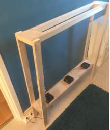 Experiments were completed to compare the drying rates of the alternative methods, and to understand the best drying variables. Throughout the experiments, the drying rates of both the tumble dryer and airer will be used as bench mark data. A prototype was assembled which uses (x3) 20W fans situated on the base of the unit to assist in the drying process. Two lines, pinned to either end of the prototype, were used to support the clothes throughout the drying process. For each experiment the clothes tested were 5 large t-shirts which were washed and the drying parameters were varied to acknowledge each drying performance.
For the testing, the items of clothing remained constant throughout, to ensure fair testing and accurate results were obtained.
Test Procedure
- Initially, the clothes were weighed to understand their dry weight to the nearest gram.
- The clothes were then placed into a washing machine and a 30-minute spin cycle was selected.
- The wet clothes were weighed to understand their wet weight prior to the drying process.
- The wet clothes were then placed into the drying appliance source.
- The clothes were re-weighed every 60 minutes, as they are underwent the drying process.
- The wet clothes were continuously reweighed until they reached a value within 5% of the original dry weight.
- The experiment was repeated until each drying source has been tested, to allow for accurate comparison testing.
3.2 Detailed Design and Analysis
Comparison graph of mass factor against drying time for the concept prototype design and the alternative clothes drying methods. The tumble dryer and airer where considered bench mark data for this experiment.
Graph 8- Graph showing mass factor against drying time for the alternative drying methods
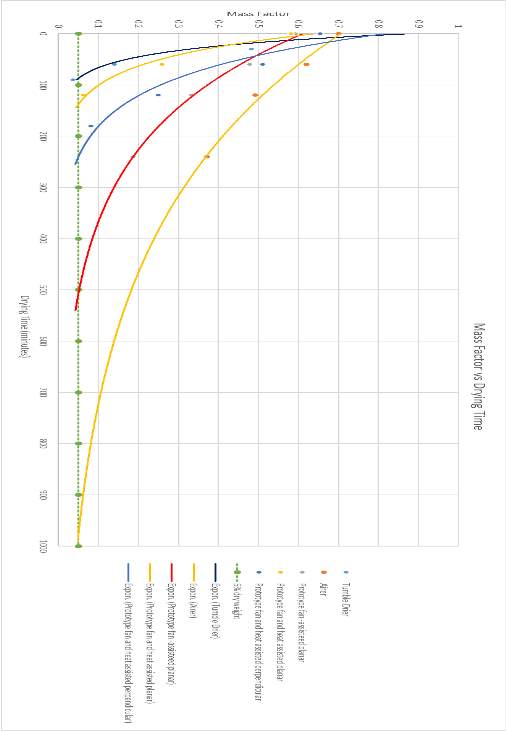
The graph displays the average experimental results exponentially and shows the point at which the clothes reach within 5% of the dry weight. The tumble dryer is the most effective clothes drying method in relation to the drying time, taking approximately 90 minutes to come within 5% of the original dry weight. The airer, when situated indoors, has the longest drying time taking approximately 1000 minutes to come within 5% of the dry weight. The room temperature, recorded at temperature of 22.7°C using a digital thermometer, was considered constant throughout the duration of the test.
For this experiment, the radiator, used as drying assistance to the prototype, was operating with a temperature of 70 °C which remained uniform throughout the experiment. This variable was controlled with the use of a thermostat.
The prototype was tested varying the operating procedures as well as its position in relation to the radiator. Within the initial test, the prototype was positioned planarly in relation to the radiator and the fans where activated, heat energy was neglected. The results for this test showed that the clothes achieved within 5% of the dry weight in approximately 530 minutes of the average drying time. Comparing this with the average drying time for the airer, shows with the use of the x3 (20W fans) the drying time was almost halved. The experiment was repeated however the drying process was fan and heat assisted and the prototype was positioned planarly in relation to the radiator. The time taken for the clothes to reach within 5% of the original dry weight was approximately 140 minutes. Showing also how using heat the acceleration of the drying process was achieved.
The prototype was then positioned perpendicularly to the radiator, the drying process was both fan and heat assisted. The average drying time for this experiment was approximately 250 minutes. Considering the drying time in relation to the positioning of the prototype, the results show that the most effective situation occurs whenever the prototype is situated planarly in relation to the radiator and the drying process is both fan and heat assisted.
Table below shows the operating costs of the alternative clothes drying methods to achieve within 5% of the original wet weight. Operating cost based on the UK average electricity cost of 14p per kWh. The heat energy provided by the radiator is considered as free energy throughout.
Table 7 – Operating cost of the drying methods to get the clothes within 5% of their dry weight
| Drying Method | Operating Time (minutes) | Power Consumption (kW) | Operating Cost |
| Tumble Drier | 90 | 4.2 | £0.40 |
| Airer | 1000 | 0 | £0.00 |
| Prototype fan assisted | 530 | 0.53 | £0.0742 |
| Prototype fan and heat assisted (planar) | 140 | 0.53 | £0.0196 |
| Prototype fan and heat assisted (perpendicular) | 250 | 0.53 | £0.035 |
Comparing operating cost in comparison with drying time, the tumble dryer dries the clothes the most quickly, taking 90 minutes for the clothes to reach within 5% of the dry weight. The operating cost of the tumble drier to effectively dry the clothes is £0.40. The operating power was calculated by attaching the tumble dryer plug into an energy adapter which connected directly into the mains. The prototype, fan and heat assisted, had a drying time of 140 minutes and had an operating cost of £0.02 to dry the clothes.
Considering the results from the experiments, the drying unit will be designed to be positioned at angle parallel to the radiator. Whenever the experiment variables were constant, the drying time frame positioned parallel to the radiator was 90 minutes faster in comparison whenever positioned at an angle perpendicular to the radiator.
3.2.1 Design Evaluation
 Concept 1 Concept 2
Concept 1
Pros – Lightweight, portable and has height adjustment features
Cons – Limited volumetric space dedicated to the drying process
Concept 2
Pros – Aesthetically pleasing design which is space efficient
Cons – Permeant radiator fixture which requires the redesign of the radiator itself.
Table 8 – Concept selection matrix
| Selection Criteria | Importance Rating | Concept 1 | Concept 2 |
| Volumetric capacity | 20% | 3 | 3 |
| Stability | 10% | 3 | 5 |
| Cost | 10% | 4 | 1 |
| Manufacturability | 5% | 3 | 1 |
| Operating Cost | 15% | 4 | 4 |
| Ease of Use | 10% | 3 | 3 |
| Noise | 20% | 4 | 4 |
| Weight | 10% | 5 | 2 |
| Net Score | 100% | 29 | 23 |
Considering the results shown in the design matrix, certain features from concept 1 will be developed to produce the final design. Concept 2 is limited, as this design can only be implemented into radiators specifically fitted to suit. The design is not universal, as currently fins found between the panels would restrict the movement of the frame. The final design will be a temporary radiator fixture positioned parallel to the radiator. Telescopic supports will be introduced to allow for manual height adjustment allowing the user to self-determine. The frame also means that the design can be stored away when not in use, minimising the volumetric space when doing so. Low powered fans will be impregnated into the base of the design, used to accelerate the drying process. The low noise fans allow the design to be situated within any room within a house hold without causing any serious interference. Developing the concept for design, the position of the double-convection radiator within a household will need to be considered.
3.2.2 Material Selection
The material selection process for this design will be completed by following these steps;
- Identify the design requirements
- Identify the materials selection criteria
- Identify candidate materials
- Evaluate candidate materials
- Select materials
- Design Requirements
Frame supports – The frame will be required to have a high strength to weight ratio. Considering the position of the model in relation to the radiator, the product will be required to be lightweight. As the length of the body on the standard model is 900mm, the frame will have required to withstand any torsional stresses that may be applied to the model. The model will be a temporary attachment to the radiator, with the option of using without radiator assisted. Considering the significant exposure to moisture, the material will be required to be waterproof. As the design may be fixated to a radiator for a significant period of time, the material will be required to have a low coefficient of thermal expansion. Height adjustment feature incorporated into the design, allowing a direct correlation between height and clothes being dried.
Base plate – Considering the base will be closest to contact with the radiator, the material will be required to have a low coefficient of thermal expansion. Considering the 900mm length of the base, the material should have a resistance to shear strength. The material should be manufacture able and also be able to be threaded, to allow permanent mounting between the frame and the fans with the base.
Top plate – Like the base frame the top support should have resistance to shear stress. Considering manufacturing, vents will be incorporated into the top support allowing condensation to escape into the surrounding atmosphere. Also the material will be subject to threading to allow permanent mounting with the frame.
Side Frame – Will have a width equivalent to the width of the radiator to ensure stability when positioned upon radiator. Square indents machined out of the inside of the frame for the magnets to be placed. To secure magnets in place an appropriate glue will be used. Will be subject to threading to allow permanent mounting with the base plate.
3.2.2 Radiator
As this models performance has a direct correlation with the assistance of a radiator, the design will be heavily influenced by the dimensions of the radiator and its position within a household. For the design of this model, the radiator will be considered double-vector with a length of 1100mm.
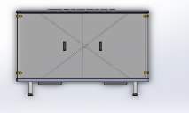
 Radiator Dimensions (28)
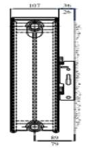
Figure 7 – Radiator Dimensions and position in relation to the mounted wall
Table 9 – Radiator Dimensions and Mounting Details
| Mounting Details | |
| Radiator Height, B | 500mm |
| Bracket Lug Heights, M | 305mm |
| Connection Centres, D | 453mm |
| Bracket Length, C | 337mm |
| Top of radiator to bottom of top lug, L | 110mm |
| Bracket at top of radiator | 100mm |
Considering the dimensions above, the tolerance of the outer width of the model must be 125mm±5mm and the inner width must exceed 107mm.
3.2.3 Selection Criteria
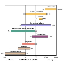 On deciding the material selection for each part, a number of factors influenced the decision process. The primary function of the material selection was its mechanical properties. The frame of the model had numerous factors influencing the process. The primary characteristic was the materials tensile strength, considering that the unit would have a maximum load of 20 kg acting upon the model at any given time. Graph 1 is a comparison graph of the primary materials tensile strength. As the polymer foam, rubbers, polymer foams and woods have relatively low tensile strengths, they will not be considered in the selection process. Glass has a low elasticity and is fragile, as it does not permanently deform therefore this material has not got the mechanical properties required. The following materials that will be considered for the material selection are composites, ceramics and metals. In order to separate these materials other mechanical properties, need to be considered. Considering these contributing factors the material selected for the support frame was metals. The selection of the metals was made considering manufacturing, strength to weight ratios, cost and availability. The materials selected for the top and bottom plate was polymers. Polymers were selected due to its ease of manufacture, cost and lightweight properties. Also as the model may become a permanent fixture within a house hold, the model will be required to be aesthetically pleasing.
Figure 8- Tensile strength of materials comparison
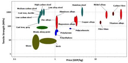
Figure 9– shows the comparison representation between the strength against price of a variety materials.
3.2.4 Material Selection
The next contributing factor to the material selection process is the ability to be processed. There are numerous ways of processing polymers, selecting the process depends on the following factors;
- Quantity and Production Rate
- Dimensional Accuracy and Surface Finish
- Form and detail of the product
- Nature of the material
- Size of the final product
The following table shows the main type of manufacturing processes of polymers.
Table 10 – The types manufacturing processes of polymers
| Manufacturing Type | Process | Pros | Cons |
| Blow Moulding | Used to manufacture hollow containers of thermoplastic polymers | Fast, efficient process with cheap tool costs and can create complex shapes | Can only process hollow tube shapes |
| Calendering | Used to manufacture sheets and films | Low cost mould tooling | Can only process sheet materials |
| Casting | Used to manufacture sheets, rods etc. | Can form large parts with low moulds cost | Process simple shapes |
| Compression Moulding | Mainly used to process thermosetting polymers | Low mould cost with little waste | High cycle time |
| Extrusion | Manufacturing of sheets, tubing etc. | Process complex parts with low mould tool costs | Part requires uniform cross-section |
| Injection Moulding | Mass production of plastics parts | High dimensional tolerance | High tooling costs |
| Rotational Moulding | Manufacturing of hollow objects | Low cost mould tooling | Long cycle time |
| Thermoforming | Manufacture of cup-shaped products | Mass part production | Only processes simple shaped parts |
Considering the shape and from of the model the material that was selected for the top and bottom platform was PC-ABS (polycarbonate-ABS). This is one of the most widely used industrial thermoplastics. PC-ABS offers the most desirable properties of both materials. The high strength and heat resistance of PC and the flexibility of ABS.
The process selected was thermoforming to manufacture the parts. This process was selected as the parts to be manufactured are non-complex. Other advantages include low tooling costs and high speed production rates. The tables below shows the mechanical, thermal and electrical properties of ABS PC.
Table 10- Mechanical Properties of PC-ABS
| Mechanical Properties | Test Method | Metric |
| Tensile Strength (Type 1,0.125”,0.2”/min) | ASTM D368 | 41 MPa |
| Tensile Modulus (Type 1,0.125”,0.2”/min) | ASTM D368 | 1900 MPa |
| Tensile Elongation (Type 1,0.125”,0.2”/min) | ASTM D368 | 6% |
| Flexural Strength (Method 1, 0.05”/min) | ASTM D790 | 68 MPa |
| Flexural Modulus (Method 1, 0.05”/min) | ASTM D790 | 1900 MPa |
| IZOD compact, notched (Method A, 23°C) | ASTM D256 | 196J/m |
| IZOD compact, un-notched (Method A, 23°C) | ASTM D256 | 481 J/m |
Table 11- Thermal Properties of PC ABS
| Thermal Properties | Test Method | Metric |
| Heat Deflection (HDT) @66 PSI | ASTM D648 | 110°C |
| Heat Deflection (HDT) @264 PSI | ASTM D648 | 96°C |
| Vicat Softening Temperature | ASTM D1525 | 112°C |
| Glass Transition Temperature (Tg) | DMA (SSYS) | 125°C |
| Coefficient of Thermal Expansion | – | – |
| Melt Point | – |
Table 12 – Electrical Properties of PC ABS
| Electrical Properties | Test Method | Metric |
| Volume Resistivity | ASTM D257 | 2x 10¹⁴ – 4.4×10¹³ ohm-cm |
| Dielectric Constant | ASTM D150-98 | 2.9-2.7 |
| Dissipation Factor | ASTM D150-98 | 0.0035-0.0032 |
| Dielectric Strength | ASTM D149-09, METHOD A | 340-90 V/mil |
Convection radiators have an operating temperature between 60°C -80°C. To ensure the material has substantial thermal capabilities, a 1.2 factor of safety was applied to the maximum operating temperature. This safety factor was applied based on the boiling point of water is 100°C. This calculated to be 96°C which was below the 112°C softening temperature for the material.
The material selected for the frame was aluminium 1100-H12. Aluminium was selected was selected because of its properties e.g. high strength to weight ratio, lightweight, shear modulus. Also, both materials were selected because of the availability and widely source able. This reduces the down time in which the model may be out of action, if failure occurs on any given part/s.
Table 13 -Properties of Carbon Fibre (29)
| Properties | metric |
| Strength to weight ratio | 39kNm/kg |
| TENSILE STRENGTH | 110MPa |
| Thermal Conductivity | 220W/m.k |
| Density | 2.8g/cm3 |
| Shear Modulus | 3.6 Msi |
| Fatigue Strength | 41 MPa |
3.3 Design Embodiment and Evaluation
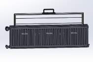
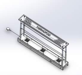 The final design of the clothes drying unit can be seen, opposite. The design was named ‘Thermopod’. The term ‘thermo’ meaning heat energy transferred from one system to another by thermal interaction. The term ‘pod’ in structural terms meaning a long, narrow container that is attached to an aircraft for carrying engines, weapons etc. As this design is long in form, and uses the heat energy from a radiator the design was called ‘Thermopod’.
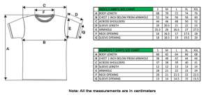
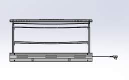
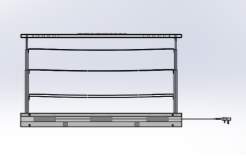
The design is specifically designed to fit double-convectors with the dimensions previously stated in table. The side frame are a 3-tiered telescopic system. They have a minimum height of 382.45mm and a maximum height if 516.10mm. The height of the support frame will have a direct relation with the amount of wet clothes that require drying. When fully extended, there is a vertical distance of 150mm between each line allowing sufficient space for clothes to be placed. The length of each line exceeds 800mm. For example, the distance between shoulders of a woman’s small t-shirt is 38mm/380mm, at least 2 t-shirts can be comfortably placed on each line.
 The top and bottom platforms were manufactured of clear ABS PC. This allowed the design to be aesthetically pleasing, preventing the design from becoming an eye sore. Due to the benefit that the low powered fans had in terms of the drying time frame, the design is incorporated with x3 20W fans on the base plate. The purpose of the fans is to, provide better circulation of the hot air released from the radiator, allowing the clothes to dry quicker. The positioning of the clothes lines in relation to the fans, means that the clothes will dry at a uniform rate regardless of the positioning from the fans provided the central passage of the air flow is not interrupted by an obstacle.
Figure 10 – http://www.personalized-tee-shirts.com/t-shirt-size-chart.html
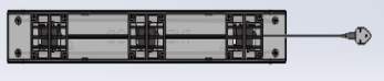 The fans are connected with a USB plug attachment, with a lead length of 1m. Allowing the model to be directly plugged into the mains.
The (x4) 9.9kg pull magnets were attached as a safety feature to provide extra stability to the model. The maximum laded weight of the model when full loaded was considered as 26.19kg. Applying a safety feature of 1.5 to the maximum weight calculates to be 39.3kg. Considering the total pull weight of the magnets is 39.6kg the magnets have sufficient strength to withstand the weights stated within the given factors of safety.
 To understand and visualise the structural strength, an FEA analysis was completed on the final design. To ensure that the upright support frames had the structural strength required to cope with the induced stresses as a result of wet clothing, a static test was performed.
Minimum Height (382.45mm) Maximum Height (516.10mm)
The FEA analysis was completed considering the maximum laded weight acting upon the model at any given time was 26.19kg. Considering the weight of the model is 6.19kg, 20kg weight was considered for the wet clothing. The force equates to a force of 256.92N. Applying a factor of safety of 3 to the design, the maximum force acting upon the model is 770.8N. There are currently 6 lines within the model upon which wet items of clothing can be placed to undergo the drying process. From the experiments, it was considered that the maximum weight acting on 1 line at any given time was 1.5kg. Applying the safety factor of 3 results in 4.5kg acting upon each line.
The support frame is a 3 tier telescopic frame. The force acting on the top tier of the frame was considered as the weight of the top platform. As the weight of the top platform is 2.01kg acting across the 4 upright supports, this equates to a weight of 0.5025g acting on 1 upright support. With a safety factor of 3 applied this results in 1.52kg, converting to a force of 14.79N. This force was considered to be acting on the top tier of the support frame, furthest from the base plate.
The second tier of the frame has 2 lines attached to it, dedicated to the drying process. The forced induced upon the second tier of the frame was considered as the potential of a full load of washing positioned on the 2 connecting lines along with the weight induced on the top tier of the frame. As the weight considered acting upon the lines, after the safety factor was applied, was 4.5kg this results in an induced weight of 9kg on both connecting lines. This results in a force of 22.07N acting upon the second tier of the frame due to the clothing. Along with the 14.79N induced upon the top tier, the total force acting upon each second tier is 36.86N.
The bottom tier of the frame has 4 lines attached to it, dedicated to the drying process. The forced induced upon the third tier of the frame was considered as the potential of a full load of washing positioned on the 4 connecting lines along with the weight induced on the 2 above tiers. The weight considered to be acting upon the tier due to wet clothing, after the safety factor was applied, was 18kg. This results in a force of 44.15N acting upon the third tier of the frame due to the clothing. The total weight considered to be acting upon the third tier of each frame was 81.01N.
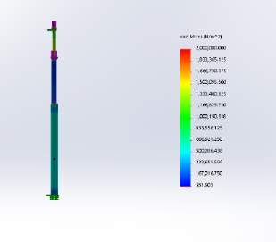 The induced forces acting on each tier of the support frame was considered to be acting on the planar face of each tier. As the top and bottom tier are connected to the top and bottom platforms, both extreme ends of the support frame was made fixed. The results of the analysis, as shown in figure, shows that the maximum stress acting upon the frame is 2 MPa. The maximum stress, shown in figure 6, is located on the bottom tier of the frame, at the line connector holder.
 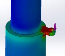 Considering the Ultimate tensile stress for aluminium is 110MPa, the supports frames have significant structural strength to withstand any induced loads. Results of the displacement test showed that the maximum deflection of the support frame, occurs directly in the middle of the frame, by a distance of 0.0037mm. This deflection distance was negligible as it was too minuscule to be considered.
The results of the FEA clearly show that the design has the structural capabilities to withstand any induced forces from wet clothes. This design clarification, allows parts to be purchased and where necessary modified through manufacturing processes.
All parts within the model will be CE marked and approved. The letters CE appear on products that are traded on the single market in the European Economic Area (EEA) [19]. The letters CE abbreviates to European Conformity and is branded on all EU official documents. The CE mark declares that the manufacturer of the product has total responsibility and that the product has met with all legal requirements. The CE mark shows that;
- The manufacturer has checked that the product meets with the EU safety, health and environmental requirements.
- The product complies with EU legislation,
- The product is allowed to be freely traded within the EU single market.
However not all products require the CE mark, only the products that are subject to specific directives. Products in the following categories do not require CE marking: chemicals, pharmaceuticals, cosmetics and foodstuffs.
CE marking applies to many products within different fields from toys, refrigerators, explosives to machinery.
The following process explains the process of CE marking;
- Identify the appropriate directive/s and harmonised standards that apply to the product
- Check the products specific requirements complies with the EU legislation
- Identify if an independent conformity assessment is necessary from a notified body
- Test the product and check its conformity to the EU legislation.
- Design the technical documentation for the product
- Place the CE mark onto the product and the EC declaration of conformity.

Figure 11- https://ec.europa.eu/growth/single-market/ce-marking_en
3.3.1 Bill of Materials (BOM)
Table 14 – Bill of materials for the clothes drying unit
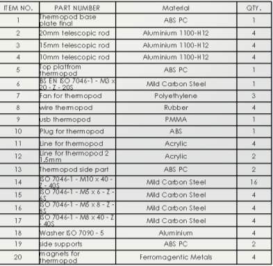
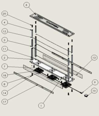 The image below labels each individual part of the model, creating a link with the BOM.
4 Discussion
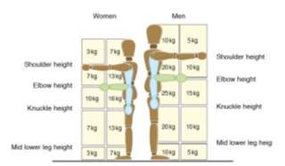 Under health and safety regulations it was important to consider the weight of the model. The general guidelines for the maximum lifting weight for a man is 25kg and for a woman is 16kg. Also when lifting above shoulder height, the maximum weight is 10kg for a man and 7 kg for a woman (30). Considering the unladed weight of the model is 5.98kg, this contributes to a safe lifting weight regardless of the gender. However, considering the maximum induced force considered to be applied upon the model was 20kg, this accumulates to a total laded weight of 26. 19kg.The weight of the laded model is above the maximum threshold of the allowed lifting weight. Within the specification it is made clear that the model should not be moved when loaded with items of clothing preventing self-damage.
Figure 12 – http://www.hse.gov.uk/pubns/indg143.pdf
From the previous experimental values, the time taken for the clothes to dry using an airer without any assistance was approximately 1000 minutes. Comparing this value using the prototype, within the same room and with the same ambient room temperature, with the assistance of the low powered fans the drying time was 530 minutes. This shows the advantage of fans within the design in terms of the drying time. Acknowledging the experimental results, the model does not require a heat source to be a functional clothes drying unit. Hence, the model can also be positioned at floor level within any room throughout the house. With the assistance of just the fans, the ambient air temperature of the room will be used to accelerate the drying time. Not only will the fans assist in the drying process, they will also help to provide better circulation of the ambient air within a room. Air circulation within a household is crucial to regulate air flow, remove impurities, prevent mould and to improve the general living quality.
However, extra and unwanted moisture content will be released into the atmosphere as a result of the evaporation of the water from the clothes. It was previously stated that a full load of washing absorbs approximately 2 litres of water, which will evaporate into the surrounding atmosphere during the drying process. Due to the bacteria and fungi found within the evaporated water, this can cause lung infections and effect those people with underlying respiratory conditions. Not only can this lead to health issues but it will also lead to the rate and quantity of dampness within a household. To remove any stale air within the room in which the model is placed, ensure good ventilation. Within the future work this issue will be considered and if necessary the model will be redesigned to counteract this issue.
Currently, a new development to the market is the Dimplex DAD25 Air dryer. The design has 6 low powered fans on its base accumulating to a power consumption of 25W. For this design to work, a clothes airer is required to position and secure the clothes parallel to the fans, allowing them to be dried. The fans, provides better circulation of the ambient temperature air, allowing the wet clothes to be dried quicker. The weight of the product is 5kg and it claims to have an approximate drying time of 8 hours, depending on the ambient room temperature. The cost of the product is €99.90 and is supplied with a 1 year guarantee. Comparing the dimplex model with the clothes the Thermopod model, shows the benefit of the heat energy supplied by the radiator. The dimplex model has an approximate drying time of 480 minutes using the ambient air temperature. Thermopod, has an approximate drying time of 140 minutes when the radiator had a uniform temperature of 70°C.
As the market leader within the clothes drying field are tumble dryers, comparisons should be made. From the experimental data, the time taken for the clothes to dry within the tumble dryer was 90 minutes. The time taken for the clothes to dry within the prototype positioned parallel to the radiator was 140 minutes. Although the tumble dyer has a faster drying time frame, the advantage of the model is its operating cost. Analysing the values within table 4, the tumble dryer required 90 minutes of operation to dry the clothes. As the power consumption was 4.2kW this resulted in an operating cost of £0.40. Comparing this value with the results of the prototype when positioned parallel and fan assisted. Although the drying time was 140 minutes, the power consumption for the prototype was 0.53kW which resulted in an operating cost of £0.07.
Considering that this specific tumble dryer on average is used twice a day, with a drying load of 5 t-shirts, this results in a yearly operating cost of £292. Operating cost based on a fixed electricity price of £0.14 kWh. A comparison with the prototype, positioned parallel to the radiator and fan assisted, with the same drying load. Results in a yearly operating cost of £51.10. By purchasing the clothes drying unit could result in a potential yearly savings of £240.90 in comparison with the tumble dryer. Throughout the experiment, it was assumed that the heat energy released from the radiator was free.
4.1 Limitations
The experimental conditions in which the experiment was completed within, limited the accuracy of the results. The experiments completed were considered to be fair testing as each time only one factor was changed, whilst the other conditions remained constant. Despite this, there was a limited control of the test environment conditions in which the clothes were drying within. Throughout the experiments, the following assumptions were made;
- The temperature of the room remained constant
- The temperature of the radiator remained constant
- The dry weight of the clothing remained constant
Materials absorption ability changes over time. Whenever certain materials which have undergone chemical treatment, they are able to transfer the moisture to the outer threads quicker. The chemical overtime washes out, rendering the yarn cavity ineffective (31). Considering these findings, the materials tested within the experiment should be new, unwashed clothing. A 5cm x 5cm dissection of the clothing item should be tested, then disposed of to ensure accurate results are obtained. A variety of materials should also be tested to improve accuracy and reliability of the experiment.
To improve the accuracy and validity of the results, the experiments would need to be completed within a controlled laboratory environment. This would allow variables such as moisture content, air flow and temperature difference to be controlled and monitored. Consequently, the results of this experiment would prove the validity of redesigning the model with a dehumidifier.
Within the experiments 6 Large T-shirts were used to understand the performance of the alternative clothes drying methods. The assembled prototype, had 2 lines dedicated to the positioning of the clothes in place, directly in line with the fans. Considering the length of the line was 600mm, and the T-shirts had a width of 420mm, in order to maximise the accuracy of the test the clothes were dried together at the same time. Considering that the clothes were over-lapping each other certain sections of the t-shirts were unexposed to the drying parameters. To provide more accurate and meaningful data, each item of clothing should have been tested individually, with each area of the material uniformly exposed to the test parameters.
The use of the radiator directly to dry clothes was not considered, as the test parameters and surrounding conditions could be controlled within the testing environment. The radiator used within the experiment, was part of a domestic central heating system, the time in which the heating remained on was limited. This meant that the test variables would change throughout the test, resulting in unreliable results.
5 Conclusion and Future Work
5.1 Future Work
Due the extra, unwanted moisture content that will be released into the atmosphere a removal source would be considered to be introduced within the design. It was previously stated that a full load of washing absorbs approximately 2 litres of water, which will evaporate into the surrounding atmosphere during the drying process. Due to the bacteria and fungi found within the evaporated water, this can cause lung infections and effect those people with underlying respiratory conditions. For further design, a dehumidifier will be considered.
Dehumidifiers are used generally used within a household appliance to reduce the levels of humidity in the air. They work by drawing the moist air over a refrigerated coil within a fan. The evaporator coil of the refrigeration device condenses the water which then gets removed. Incorporating a dehumidifier into the design, could potentially provide the opportunity to recirculate the water back into the water system. However, this would only work if the clothes dryer became a permanent fixture to the radiator. Similar to concept 2 within the design selection, the dryer would be positioned parallel between the convector panels. However, this would require an alteration to the current radiator design, as the fins between the panels would be required to be moved.
Despite the health benefits that would arise with the introduction of the dehumidifier, the decision was made not to incorporate this into the design. The current primary competitors to this clothes drying unit is the tumble dryer. Currently on the market the RRP costs of the tumble dryer starts at £119. This clothes drying unit has an RRP of £121.33. As the current price is slightly more expensive than the cheapest tumble dryer on the market, the addition of the dehumidifier would result in an inflation of the current cost. Considering that during the drying process of a full load of washing approximately 2 litres of water get evaporated into the atmosphere, the dehumidifier would require a suitable volumetric capacity. The shape and design of the model, the dehumidifier will be custom built to incorporate into the design. On the market the current RRP of dehumidifiers with a volumetric capacity between 2L-2.4L starts at £29.99. However, the cost of the dehumidifier specifically designed for this unit will exceed this price. To understand the advantages of incorporating a dehumidifier, the experimental tests must be repeated, within controlled environmental conditions. This would allow the humidity to be measured, prior to and post testing.
The addition of the dehumidifier may increase the initial RRP price of the clothes drying unit, however considered the potential health risks and moulding occurred from the additional moisture the feasibility of the dehumidifier must be considered.
Analysing the final design of the clothes drying unit, currently the radiator has to be a certain dimension for the model to be compatible with it. If the radiator is outside of the tolerance required, the model cannot be placed at a position parallel to the radiator, limiting the performance of the model. In order to make this model versatile with all double convection radiators, width adjusting tracks will be introduced to the model. The tracks are connected to the side boards positioned either side of the base plate. The purpose of the side boards is to provide stability to the model whenever it’s positioned parallel to the radiator. To assist with stability, high strength pull magnets are implemented into the side boards. However, to fully secure the model when mounted onto the radiator width adjusting sideboards will be introduced to the design. The maximum and minimum widths will however be influenced by the individual user’s radiator and radiator position in relation to the connected wall. I feel it would be a beneficial design altercation, considering the low manufacturing and part cost in doing so. Potentially, preventing catastrophic failure through impact on the ground when falling from a height through instability. However, in order in implement tracks within the design, electromagnets will be required in replace of the standard magnets. The electromagnets will however increase the power consumption of the unit.
Currently, the Thermopod model is considered as the standard model with a length of 900mm. To improve the versatility and compatibility with all types of double-convection radiators, future models will be developed with a variety of available lengths. The current lengths of the double–convection radiators ranges from 600mm to 1800mm. Future standard models will be developed with lengths of 600mm,900mm and 1200m.
5.2 Final Summary
The primary aim of the project was to design a functioning clothes drying unit which was a temporary fixture to a radiator. The model was compared throughout, with the performance of the tumble dryer and clothes airer. Initially the bench mark data was collected which allowed performance and operating parameters to be compared. A prototype clothes drying unit was manufactured and assembled, which allowed the optimum performance parameters to be obtained in relation to the position with the radiator. The data obtained from the tumble dryer and clothes airer test, was used as a comparison to the data obtained with the prototype testing. The results of the experiments showed the effectiveness of both heat and air circulation in terms of drying time frame, when positioned parallel to the radiator.
To develop more accurate and trustworthy results, the experiment should be repeated within a controlled environment were the surrounding conditions could be monitored closely. Also a large quantity and variety of clothing should be tested to develop a larger database of data providing more meaningful results.
Considering the drawbacks stated from the use of tumble dryers and airers to dry wet clothes, there is an opportunity for this clothes drying unit to be further developed and marketed. The design allows the wet clothes to be dried with a power consumption to less than 80% of that of a tumble dryer. The design is also capable of having a drying time which is 60% more than that of a tumble dryer. The closest competitor to the Thermopod model, is the Dimplex clothes air dryer. Although it has a lower operating cost, it takes approximately 480minutes to dry the wet items of clothing. The Dimplex dries the clothes, by providing better circulation of the ambient room temperature air with the use of 6 low powered fans. A clothes airer is also required for the Dimplex to fully function, to hold and position the wet clothes.
6 References
[1] http://www.metoffice.gov.uk/news/releases/2016/winter-statistics
[2] Cihat Arslanturk, A.Feridun, Ozguc, Optimization of a central heating radiator, Science Direct, Applied Energy 83 (2006) 1190-1197
[3] Cihat Arslanturk, A.Feridun, Ozguc, Optimization of a central heating radiator, Science Direct, Applied Energy 83 (2006) 1190-1197
[4] Cihat Arslanturk, A.Feridun, Ozguc, Optimization of a central heating radiator, Science Direct, Applied Energy 83 (2006) 1190-1197
[5] K.J. Colthorpe, The performance of radiators and convectors, The Heating and Ventilating Research Council, technical note no. 3, 1959.
[6] K. Waters, R.H. Fine, the performance of radiators and convectors using medium temperature hot water, The Heating and Ventilating Research Association, laboratory report no. 59, 1969.
[7] I.C. Ward, Domestic radiators: performance at lower mass flow rates and lower temperature differentials than those specified in standard performance tests, Building Services Engineering Research and Technology 12 (3) (1991) 87–94.
[8] D.J. Harris, Use of metallic foils as radiation barriers to reduce heat losses from buildings, Applied Energy 52 (1995) 331–339.
[9] S.B.M. Beck, S.G. Blakey, M.C. Chung, the effect of wall emissivity on radiator heat output, Building Services Engineering Research, and Technology 22 (3) (2001) 185–194.
[10] S.M.B. Beck *, S.C. Grinsted, S.G. Blakey, K. Worden, A novel design for panel radiators, Applied Thermal Engineering 24 (2004) 1291-1300
[11] S.M.B. Beck *, S.C. Grinsted, S.G. Blakey, K. Worden, A novel design for panel radiators, Applied Thermal Engineering 24 (2004) 1291-1300
[12] S.M.B. Beck *, S.C. Grinsted, S.G. Blakey, K. Worden, A novel design for panel radiators, Applied Thermal Engineering 24 (2004) 1291-1300
[13] S.M.B. Beck *, S.C. Grinsted, S.G. Blakey, K. Worden, A novel design for panel radiators, Applied Thermal Engineering 24 (2004) 1291-1300
[14] Manuel R.Conde*, Energy Conservation with Tumbler Drying in Laundries, Applied Thermal Engineering, Volume 17, No12, 1997
[15] J. Deans *, The modelling of a domestic tumble dryer, Applied Thermal Engineering 21 (2001) 977-990
[16] J. Deans *, The modelling of a domestic tumble dryer, Applied Thermal Engineering 21 (2001) 977-990
[17] J. Deans *, The modelling of a domestic tumble dryer, Applied Thermal Engineering 21 (2001) 977-990
[18] J. Deans *, The modelling of a domestic tumble dryer, Applied Thermal Engineering 21 (2001) 977-990
[19] c, Department for Business, Energy, and Industrial Applications, 8/10/12
[20] Himsar Ambarita et.al, Performance of a clothes drying cabinet by utilizing heat from a split-type residential air conditioner, Thermal Engineering, 2016
[21]http://www.theboltonnews.co.uk/news/11679475.Dryingclothesonaradiatorcouldkillme, 19/12/14
[22] S.M.B. Beck *, S.C. Grinsted, S.G. Blakey, K. Worden, A novel design for panel radiators, Applied Thermal Engineering 24 (2004) 1291-1300
[23] S.M.B. Beck *, S.C. Grinsted, S.G. Blakey, K. Worden, A novel design for panel radiators, Applied Thermal Engineering 24 (2004) 1291-1300
[24] S.M.B. Beck *, S.C. Grinsted, S.G. Blakey, K. Worden, A novel design for panel radiators, Applied Thermal Engineering 24 (2004) 1291-1300
[25] J. Deans *, The modelling of a domestic tumble dryer, Applied Thermal Engineering 21 (2001) 977-990
[26] J. Deans *, the modelling of a domestic tumble dryer, Applied Thermal Engineering 21 (2001) 977-990
[27] https://www.stratasysdirect.com/wp-content/themes/stratasysdirect/files/material-datasheets/fused_deposition_modeling/FDM_PC_ABS_Material_Specifications.pdf
[28]http://www.quinnradiators.com/wpcontent/uploads/2013/08/PanelBrochure_low-res.pdf
[29]http://www.makeitfrom.com/material-properties/1100-H12 Aluminum#Properties
[30]http://www.workplacesafetyadvice.co.uk/guide-manual-handling-lifting-techniques.html
[31] https://www.freeletics.com/en/knowledge/moisture-transfer-in-clothing/
[32] https://blogs.oracle.com/utilities/americas-most-unpopular-way-of-saving-energy-is-one-of-europes-favorites
[33] http://www.which.co.uk/reviews/tumble-dryers/article/energy-saving-tumble-drying-tips
7 Appendices
The appendices are an opportunity to provide secondary material in support of the description in the body of the report. In principle, the reader need not look at the appendices and no specific marks are awarded for this section.
Sample content:
7.1 Appendix A Analysis data
e.g. FEA inputs/outputs, etc.
7.2 Appendix B Specification sheets
e.g. Technical datasheets from suppliers for bought in components
7.3 Appendix C Drawing Package and BOM
A detailed drawing package would be appropriate along with Bill of Materials.
7.4 Appendix D Questionnaire Results
Results of questionnaires used to evaluate the design and/or identify requirements
Cite This Work
To export a reference to this article please select a referencing stye below:
Related Services
View all


Related Content
All TagsContent relating to: "Energy"
Energy regards the power derived from a fuel source such as electricity or gas that can do work such as provide light or heat. Energy sources can be non-renewable such as fossil fuels or nuclear, or renewable such as solar, wind, hydro or geothermal. Renewable energies are also known as green energy with reference to the environmental benefits they provide.
Related Articles

DMCA / Removal Request
If you are the original writer of this dissertation and no longer wish to have your work published on the UKDiss.com website then please: