Development and Testing of Composite Corrugated Core of Camber Morphing Wing Structure
Info: 19523 words (78 pages) Dissertation
Published: 16th Dec 2019
Tagged: Sciences
ABSTRACT
In this study, the student is required to develop and test the composite corrugated core for camber morphing wing structure. In the introduction, the student will explain in detail about the definition of the composite structure followed by the example of the composite. After that, the student will describe about the types of the matrix used between the layer of the materials such as polymer matrix composites, metal matrix composite and ceramic matrix composites. Other than that, this topic also included with the detail explanation about the structure of the composite corrugated which referred to the flexible flap as well as the morphing structure.
In the literature review section, the student will include the experiment that has been carried out by manufacturing company, university research and many more. Some examples included in this topic are from the research of Bristol University related to the aircraft that use morphing wing design. The other examples referred for this chapter are project by the European Research Council, research by the Swansea University, the research related to the performance of the UAV by using smart material, morphing experiment carried by the CRG Corporate Center and surface control research by the FlexSys Inc. Moreover, the student will also describe three types of composite used in previous experiment in order to develop camber morphing wing structure such as Shape Memory Alloy (SMA), Carbon fibre and Fibre glass. The advantages and disadvantages for each experiment are provided.
At the end of this report, the student will describe the steps of fabrication for the materials as well as the result for the experiment. The results are then presented in the form of graph and table for a better comparison between the previous and latest experiments. Moreover, the student also will provide the result for the experiment in this report followed by the discussion regarding on the chosen material. Lastly, the student will conclude all the important point that has been made within this report as the proof.
ACKNOWLEDGEMENT
In this research of development and testing of composite corrugated core for camber morphing wing structure, there are a lot of supports and involvement from others such as lecturers, technicians, STRAND Aerospace Malaysia and friends as well as family members which gave motivation in order to complete this research.
First of all, I would like to express my gratitude from my heart to Dr. Rukshan Navaratne who is a Senior Lecturer in Aeronautical Engineering Department for helping me as my supervisor for this study. In this project, I also want to say thank you to him as he willing helped me through all hardship without any complaints since this is my first task related to Aeronautical field. Other than that, I would like to say thank you to Lalita Gandhi, one of the Aircraft Maintenance Lecturer from Faculty of Computing, Engineering and Science for giving me motivation in order to successfully finishing this project within the time constraint as well as to Clive Bennett, the Senior Technical Officer and Adam Stubbs Aircraft Maintenance Workshop Technician who involves during the fabrication and testing for the specimen.
In addition, the praise also goes to STRAND Aerospace Malaysia department especially to Dr. Shahid Ibrahim and my mentor Mr, Muhammad Anas Bin Ahmad for giving some advice during the making of this report. The advice given by both of them was very clear and useful for completing the technical report.
Last but not least, appreciation to all my family members and friends which always supporting me from behind and keep motivating me when I feel de-motivate during the study in the UK which is far away from my country.
TABLE OF CONTENT
PAGES
ABSTRACT II
ACKNOWLEDGEMENT III
TABLE OF CONTENT IV
LIST OF FIGURES VII
LIST OF TABLES IX
LIST OF ABBREVIATION X
CHAPTER 1 1
INTRODUCTION 1
- WHAT IS COMPOSITE STRUCTURE? 1
- TYPES OF MATRIX 3
1.2.1 POLYMER MATRIX COMPOSITES (PMC) 3
1.2.2 METAL MATRIX COMPOSITES (MMC) 4
1.2.3 CERAMIC MATRIX COMPOSITES (CMC) 6
- CORRUGATED COMPOSITE STRUCTURE 7
- MORPHING STRUCTURE 8
CHAPTER 2 13
LITERATURE REVIEW 13
2.1 CARBON FIBRE 13
2.2 FIBRE GLASS 16
2.3 SHAPE MEMORY ALLOYS 20
2.4 MORPHING AIRCRAFT RESEARCH BY BRISTOL UNIVERSITY 27
2.5 FLEXFOIL BY FLEXSYS 28
2.6 SMART MATERIAL FOR UAV PERFORMANCE BY
SWANSEA UNIVERSITY 30
2.7 MORPHING WING STRUCTURES FOR CRUISE MISSILES 32
CHAPTER 3 34
METHODOLOGY 34
3.1 STEP OF FABRICATION 34
3.1.1 DRAWING AND 3D PRINTING THE MOLD 34
3.1.2 APPLYING WAX ON MOLD 37
3.1.3 APPLYING MOLD RELEASE AGENT 37
3.1.4 LEVELING THE MOLD 38
3.1.5 APPLYING EPOXY RESIN 38
3.1.6 PREPARING CARBON FIBRE FABRIC 41
3.1.7 CURING THE COMPOSITE 42
3.1.8 DEMOLD THE CARBON FIBRE 43
3.2 STANDARD TESTING PROCEDURE 44
3.2.1 BENDING TESTING 44
3.2.2 TENSILE TEST 46
CHAPTER 4 49
RESULT AND DISCUSSION 49
4.1 RESULTS FOR CARBON FIBRE 49
4.1.1 EXPERIMENTAL RESULT FOR BENDING TEST 49
4.1.2 THEORETICAL COMPARISON 51
4.1.3 EXPERIMENTAL RESULT FOR TENSILE TESTING 51
4.1.4 THEORETICAL COMPARISON FOR TENSILE TESTING 54
4.2 RESULTS FOR FIBRE GLASS 55
4.2.1 EXPERIMENTAL RESULT FOR BENDING TEST 55
4.2.2 THEORETICAL COMPARISON 57
4.2.3 EXPERIMENTAL RESULT FOR TENSILE TESTING 57
4.2.4 THEORETICAL COMPARISON FOR TENSILE TESTING 59
4.3 DISCUSSION 61
CHAPTER 5 63
CONCLUSION 63
5.1 CONCLUSION 63
5.2 RECOMENDATION 63
REFERENCES 66
LIST OF FIGURES
PAGES
Figure 1.1.1 Example of Composite Structures 1
Figure 1.1.2 Steps to Fabricate Composite Material 2
Figure 1.2.1 Types of Matrix in Composites 3
Figure 1.2.1.1 Examples of Polymer Matrix Composites 4
Figure 1.2.2.1 Example of Metal Matrix Composite Application 5
Figure 1.2.3.1 Ceramic Matrix Turbine Nozzle 7
Figure 1.3.1 Corrugated Composite Structure 8
Figure 1.4.1 Example of Morphing Structure 9
Figure 1.4.2 Analysis of Morphing Structure 10
Figure 1.4.3 Morphing Wing from Flexsys 11
Figure 2.1.1 Example of Carbon Fibre Sheet 14
Figure 2.1.2 Cracked of Carbon Fibre Plate 16
Figure 2.2.1 Sample of Fibre Glass 17
Figure 2.2.2 Relationship between Thermal Expansion and Temperature 19
Figure 2.3.1 Example of Shape Memory Alloy Sheet 20
Figure 2.3.2 Two Phases for Shape Memory Alloy 21
Figure 2.3.3 6 Phases of Shape Memory Alloy Deformation 21
Figure 2.3.4 Deformation for Austenite and Martensite Structure 22
Figure 2.3.5 Actuating Shape Memory Alloy 23
Figure 2.3.6 Microscopic Effect of Shape Memory Alloy 23
Figure 2.3.7 One Way Memory Effect 25
Figure 2.3.8 Two Way Memory Effect 25
Figure 2.3.9 Sample of Shape Memory Polymer 26
Figure 2.3.10 Application of SMA Material 27
Figure 2.5.1 Control Surface for FlexSys Morphing Structure 29
Figure 2.5.2 Control Surface Design by FlexSys 29
Figure 2.6.1 Concept of Morphing Design 30
Figure 2.6.2 Optimisation of the Morphing Model 31
Figure 2.6.3 Corrugated Skin 32
Figure 2.6.4 Morphing Camber Configuration 32
Figure 3.1.1.1 2 Dimension Bottom Mold 34
Figure 3.1.1.2 Bottom Mold in 3 Dimensions 35
Figure 3.1.1.3 Top Mold Drawing 35
Figure 3.1.1.4 Top Mold in 3 Dimensions 36
Figure 3.1.1.5 Mold Fabrication 36
Figure 3.1.1.6 Mold Final Product 36
Figure 3.1.3.2 Fabrics Covered by Release Films 38
Figure 3.1.5.1 Types of Resin and Hardener Used in the Experiment 39
Figure 3.1.5.2 Weighting the Materials 40
Figure 3.1.6.1 Drawing on Vacuum Bag Plastics 41
Figure 3.1.6.2 Layering the Fabrics 42
Figure 3.1.7.1 Curing Process for Corrugated Structure 43
Figure 3.1.8.1 Removing Carbon Fibre from Mold 43
Figure 3.1.8.2 Corrugated Carbon Fibre 44
Figure 3.1.8.3 Smaller Piece of Specimen 44
Figure 3.2.1.1 Illustration for 3 and 4 Point Bending Test 45
Figure 3.2.2.1 Uniaxial Tensile Machine 47
Figure 4.1.1.1 Specimen Placed on 3 Point Bending Test 49
Figure 4.1.1.2 Carbon Fibre Specimen under Testing 49
Figure 4.1.1.3 Maximum Deflection for Carbon Fibre 50
Figure 4.1.1.4 Deformation on Specimen 2 Carbon Fibre 50
Figure 4.1.3.1 Carbon Fibre Specimen on Tensile Test 51
Figure 4.1.3.2 Broken Pieces of Carbon Fibre 51
Figure 4.1.3.3 Curve for Specimen 1 52
Figure 4.1.3.4 Extension for Carbon Fibre Specimen 2 52
Figure 4.2.1.1 Testing Glass Fibre Specimen 55
Figure 4.2.1.2 Bending the Glass Fibre 55
Figure 4.2.1.3 Deformation for Fibre Glass 56
Figure 4.2.1.4 Glass Fibre Bending Curve 56
Figure 4.2.3.1 Fibre Glass Specimen on Tensile Test Machine 57
Figure 4.2.3.2 Failure on Fibre Glass Specimen 57
Figure 4.2.3.3 Extension for Fibre Glass Specimen 1 58
Figure 4.2.3.4 Specimen 2 Extension Curve 58
Figure 4.3.1 Comparison of 4 Different Specimens 60
Figure 4.3.2 Example of Tensile Testing Result 61
LIST OF TABLES
PAGES
Table 2.1.1 Strength to Weight Ratio for Specific Materials 15
Table 2.1.2 Ultimate Strength Value for Certain Materials 15
Table 2.2.1 Properties for 2 Different Fibre Glass 18
Table 3.2.1.1 Comparison between 3 and 4 Point Bending 46
Table 4.1.3.1 Tested Carbon Fibre Properties 53
Table 4.1.3.2 Maximum Tensile for Carbon Fibre Specimen 53
Table 4.2.3.1 Properties for Fibre Glass 59
Table 4.2.3.2 Maximum Tensile stress for Fibre Glass 59
LIST OF ABBREVIATION
GRP Glass Fiber Reinforced Plastic
PMC Polymer Matrix Composites
MMC Metal Matrix Composites
CMC Ceramic Matrix Composites
Cu-Al-Ni Copper-Aluminium-Nickel
NiTi Nickel-Titanium
PVA Polyvinyl Alcohol
DARPA Defense Advanced Research Projects Agency
CHAPTER 1
INTRODUCTION
- WHAT IS COMPOSITE STRUCTURE?
Composite is a combination of different materials in order to produce a new special material. Usually composites consist of more than two materials which are combined in layered form structures. Composite structures also known as reinforced materials. One of the reasons of creating a composite structure is to counter the weaknesses of the previous materials and increases the properties of the materials. For examples, Glass Fiber Reinforced Plastic (GRP) is one of the oldest composite structures which are manufactured by combining fibre glass and plastics in order to produce a strong but not brittle structure. In this situation, the previous researches use this material to replace metal plates because the composite is stronger and lighter.
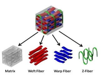
Figure 1.1.1 Example of Composite Structures
During the making of composite materials, the adhesive is used to bond each material in order to reduce fractures to the composite structures while it is being used. This layer of adhesive is usually referred as matrix. The other function of matrix is to reduce damage and make the structure stronger as well as stiffer. The different types of fibres used to manufacture composite are asbestos, carbon, glass, silicon carbide and many more. There are also different types of matrix such as metal, plastics, ceramics and concretes. The following picture indicates the steps of fabricating the composite structures by hand. (Explain that Stuff, 2016)
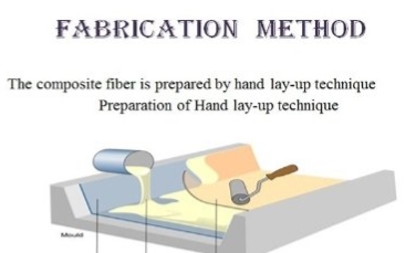
Figure 1.1.2 Steps to Fabricate Composite Material
The use of composite materials will provide advantages and disadvantages to the material itself. The advantages of using composite materials are that it is a light weight material and possess high strength and stiffness ratio. Other than that, the use of composite materials will improve the corrosion resistance and fatigue to the material as well as able to tailor lay up of the optimum stiffness and strength. Composite materials also have low electrical conductivity and thermal expansion as well as have good damping characteristic.
However, composite materials also have disadvantages to the material such as the raw material to build the composite is very expensive and the cost of fabrication and assembly is very high. Furthermore, this material can also react if the temperature and moisture is different as well as it is very hard to repair when the structure is damaged. The other disadvantages for this material are that it is very sensitive to the impact damage and will have higher chance to have hidden damage.
- TYPES OF MATRIX
There are three types of matrix that widely used in common composites structure. The three types are Polymer Matrix Composites (PMC), Metal Matrix Composites (MMC) and Ceramic Matrix Composites (CMC). The types of matrix can be recognising by the following criteria.
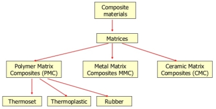
Figure 1.2.1 Types of Matrix in Composites
1.2.1 POLYMER MATRIX COMPOSITES (PMC)
Polymer Matrix Composites is the most popular types of composites since it is low in cost and easy to fabricate. It is also known as Reinforced Plastic. This types of matrix consist of resin which layered by the phase of reinforced fibre dispersed. The resins used in this type of composite possess very high tensile strength value of 140 MPa or 20,000 psi which also acts as low resistance to the impact force.
The application of this type of composite can be found in canoes, kayaks, body of a boat, radio controlled vehicles and aerospace structures. Other than that, polymer matrix composites are also used in fabrication of clutch lining, Kevlar, brakes and many more. The polymer matrix composites also can be identified by the characteristics of its properties. The characteristics are:
- High value of tensile strength
- The stiffness is very high
- High in fracture toughness
- Good resistance to abrasion
- Good resistance to puncture
- High corrosion resistance
- Low fabrication cost
However, the disadvantages of this type of composite are that it has low resistance of thermal energy and high coefficient value of thermal expansion. (Substech.com, 2016)
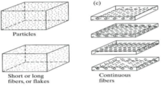
Figure 1.2.1.1 Examples of Polymer Matrix Composites
1.2.2 METAL MATRIX COMPOSITES (MMC)
The layup for these types of composites consists of two or more layer of composites where one of them has to be metal, organic compound or ceramics. These types of composites use one of the composite materials called cermet which is the mixture of ceramic and metallic materials to glue between the layers together. This type of composite also called as hybrid composite whose surface is coated by the reinforcement materials in order to reduce the chemical reaction to the surface of the composites. Usually the surface of this type of composite can be coated by using titanium boride and nickel.
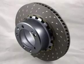
Figure 1.2.2.1 Example of Metal Matrix Composite Application
The matrix order for this composite is different from other sandwiched materials because it uses a material called monolithic material which placed between the structures. The composite usually work with a light metal material such as titanium, aluminium and magnesium which provide a good support to the reinforcement. In case of hot application, alloy which contains cobalt nickel are used as the matrix.
There are three basic method of fabricating the Metal Matrix Composite. The methods are casting, high pressure diffusion bonding and powder metallurgy. Usually, the casting method and the diffusion bonding method are used to reinforce the continuous fibre in metal matrix composites and powder metallurgy is use for discontinuous reinforcement.
The advantages of using MMC rather than monolithic metal are that MMC have a higher ratio of strength to density as well as stiffness to density. Other than that, metal matrix composite also has a better resistance to the fatigue and has a lower thermal expansion coefficient. It also produces a better strength and generate low creep rate at high temperature. The MMC composite structure is also capable of withstand higher temperature and fire proof. After that, this type of composite produce a great resistance to any reaction and it is also a good conductor for thermal and electrical conductor. It also has a high value of transverse strength and stiffness as well as the ability to absorb no moisture.
However, the MMC composite also has some disadvantages if it is compared to other composite structures such as polymer and monolithic metal structures. The disadvantages are that some of the fabrication of MMC composites might cost higher in terms of the price since this type of composite uses titanium as one of the materials. Other than that, the technology used in this composite is still in the development phase. Therefore, it is unable to produce better results since the service experience is still limited in terms of the research and development. (Machinedesign.com, 2016)
1.2.3 CERAMIC MATRIX COMPOSITES (CMC)
This type of composite is one of the divisions under the composite materials which use ceramic fibre in order to create the different composite layers. The product of this type of composite structure also can be referred to Ceramic Fibre Reinforced Ceramic. The reason for using ceramic fibre between the layers is to counter the weaknesses of previous ceramic matrix which provides low fracture toughness, low resistance to thermal shock and brittle in nature.
After the development of the ceramic matrix composites, some of the weaknesses could be improve by the new composite structure which gives a higher stability to the oxidation temperature and also increases the toughness of the material.
The ceramic matrix composite also produces new properties to the structure compared to the ceramics that are widely used in the world. The properties are that the new ceramic can elongate up to 1% of the total length before rupture. The improvement of the new ceramic matrix also produces a material which introduces higher fracture toughness to the composite. Other than that, the new development leads to a material that has an extreme resistance to the thermal shock. Lastly, the capacity to withstand a dynamic load also improved in this new material.
The advantages of this ultra hard composite structure are that it produces a very high value in terms of the strength and hardness of the material. This material also manufactured as a good resistance to any corrosion and wears as well as provides a better fracture toughness. The production of this material which possesses these properties is a key ingredient to make it the best and reliable material to be selected as the reliable material especially for the large parts.
The application for this type of composite can be found in centrifugal and rotary pumps which can be used in aggressive as well as abrasive conditions and high temperature situations. Other than that, ceramic matrix composite also can be used as face seal in valve parts such as actuators in mining industries, gas and petrochemical sectors. (Virial.ru, 2016)
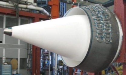
Figure 1.2.3.1 Ceramic Matrix Turbine Nozzle
- CORRUGATED COMPOSITE STRUCTURE
Generally, a corrugated structure can be defined as the configuration in terms of the layered composite materials. It is also referred to the series of the layer such as grooves or parallel which is used to improve the strength and the rigidity of certain materials. The behaviour of this type of material is that it is very effective to use and simple to fabricate. Other than that, corrugated composite structure is a lightweight material which provides the best stability. It can also handle the buckling load without failure and possess the ability of absorbing the external energy.
In this case, many researchers tried to develop an innovative structure of corrugated composite which uses the combination of advanced materials for their geometries. The previous research has led the scientist and engineers into deeper research for this material. One of the researches has used the flexible degree of freedom into the corrugated composite structure in order to change the shape of the structure. The others researchers have exploited the corrugated panel into extreme anisotropic phase. The advantages of using the corrugated structure is that is can cover the range of applications from the beams with corrugated steel to the advanced engineering structure such as aircraft morphing wing structure. (Sciencedirect.com, 2016)
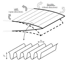
Figure 1.3.1 Corrugated Composite Structure
- MORPHING STRUCTURE
Generally, morphing structure can be defined as a composite structure that is able to transform in terms of the shape and configuration. In the aerospace industries, morphing structure can be referred to the ability of the material to continuously switch shape in a drastic manner which can also be called the development of the Smart Intelligent Structures. This structure is able to flex the outer skin of the aircraft wing by manipulating the internal wing mechanism. The research about the morphing wing structure can be applied to the aircraft in order to reduce the drag during takeoff, landing and level flight. Current aircraft equipped with the winglet cannot change the shape of the wing without manipulating the aerodynamic performance of the aircraft. However, the morphing wing design can change the wing shape at any time without costing any loss to the performance of the aircraft.
Most of the conventional aircraft are built with fixed wing design which consists of retractable flaps in order to change the efficiency of the aircraft and the way the aircraft are manoeuvred. However, this kind of deployable flaps will provide some conflicts and limitations for the aircraft during the flight since it can change the performance of the aircraft. In order to counter this limitation, aircraft manufacturer tried to develop a new generation of materials which can manipulate the geometry of the aircraft wing without reducing its efficiency. (Sciencedirect.com, 2016)
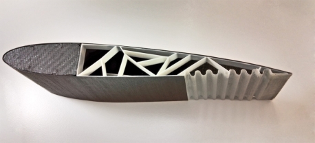
Figure 1.4.1 Example of Morphing Structure
This new material is called as morphing wing structure which is able to optimise the wing shape without costing extra fuel consumption and its effectiveness. The concept of morphing structure is design according to the bird’s wing which can morph during the flying and attacking the pray by changing the configuration of the wing. During the flight, birds also control the twist and camber of their wing which provides a better control during the flight. This new development of the wing structure will give different challenges to the pilot because the design provides a different flight control law. The reason for this is that the centre of aerodynamic and aircraft control will differ during the change in morphing configuration.
The development of this new wing structure is very effective to the aircraft since the manufacturers can reduce the cost for designing other specific wing shapes for certain aircraft. Nowadays, the demand for the morphing wing structure is increasing due to the aeroelastic behaviour as well as its ability of change the wing configuration. The other advantage of this type of wing structure is that it can widen the flight envelope while improving the performance of the aircraft and it can increase the flight range by reducing the drag of the aircraft. Other than that, a morphing wing structure can also reduce the vibration and flutter during manoeuvre. The morphing structure can also increase the performance of the aircraft by replacing the conventional control surface during the flight control.
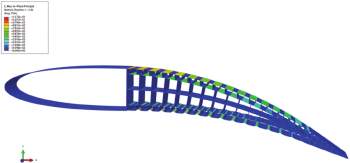
Figure 1.4.2 Analysis of Morphing Structure
Each change in the shape of the morphing wing type design will required the magnitude and time for different application during the flight. However, in order to increase the performance of the aircraft, the morphing wing structure will only need a small amount of vibration and the resulting change in the wing shape is very fast so that the pilot can control the vibration of the aircraft during the flight. This morphing structure not only provides a single solution for a certain situation but it is varied depending on the application which required the wing to change shape. So, it is proof that morphing wing structure is required for an airplane to achieve the goal of increasing the performance and function of the aircraft while maintaining the weight requirements of the aircraft.
Basically, morphing structure can be characterized by two different types which are planform and compliance. The planform type is referred to the changes of the wing by using rigid mechanisms and the compliance type is referred as the twisted wing or using the compliance mechanisms. In order to change the shape of the wing, some control systems are required such as system for controlling the vibration and the shape control system. Usually, in vibration control, the force is applied directly to the structure. Meanwhile, for the system that control the shape of the wing, some actuator in the wing structure are needed as the tool to manipulate the wing shape which will be monitored by the sensors as the guide to the deflection.
The configuration of the morphing structure also includes some motion such as wing sweep, extension of the wing and the folding of the wing. This motion can be applied to the flight control systems which only involve small changes of the wing geometry in order to improve the control of the aircraft. Nowadays, most of the passenger aircraft use mechanical systems which are complex to install and required high cost to maintain as well as heavy airframe structure. By using morphing design structure, most of these problems can be reduce since it can provide a better control of performance of the aircraft such as the twist of the wing, change in wing chamber, wing extension and many more. (Sciencedirect.com, 2016)

Figure 1.4.3 Morphing Wing from Flexsys
Therefore, this project is formed and it is concerned with the proper function of the corrugated wing core structure in the aerospace industries. Basically, this report is divided into 5 different chapters.
In chapter 1, the student explained about the definition of the composite. The student explained about the types of matrix used in the composite structures that have been produced which are known as Polymer Matrix Composites, Metal Matrix Composites and Ceramic Matrix Composites as well as the application and the example of each types. After that, the student explained about the meaning of corrugated composite structure and provided some example for the topic. The student also able to explained about the morphing structure in terms of the meaning of morphing and the example of application for it. The student was also able to relate the creation of morphing structure to the development of the future aircraft design.
Chapter 2 is called literature review which will describe the previous development of the morphing wing structure. This chapter will include the research that have been done by both university and aircraft manufacturer in order to find the best material to use in a commercial aircraft as morphing wing structure can improve many aspect of the aircraft such as the stability, control and many more.
For the chapter 3, the student is required to fabricate and test the material. In this chapter, the student will show the fabrication steps for the materials. The student also needs to explain the reason for choosing certain material. Moreover, the student will provide the advantages and disadvantages of choosing certain materials for this experiment in order to finalize the best material to be used as chamber morphing structure on the commercial aircraft.
In chapter 4, the student will discuss the test result for the test which in this case the student will use some testing methods such as the deflection of the fabricated material, bending and buckling test, elongation and deformation testing as well as tensile testing. All of the testing will be carried out at the University of South Wales. The result of all the testing will be presented both in graphical and table form in order to compare the result for a clear understanding.
Lastly, the summary of the testing and research will be concluded in chapter 5. In this part, one of the composite structures will be chosen as the best material to fabricate a reliable morphing wing in a commercial aircraft.
CHAPTER 2
LITERATURE REVIEW
2.1 CARBON FIBRE
Carbon fibre can be defined as a material that is made from aligned carbon crystals along the axis which form a shape of honeycomb crystals that is organized in into ribbon flattened pattern. The ribbon pattern makes the carbon fibre stronger since the ribbons align the pattern within the fibres. The fibre used in the carbon fibre is measures around 5-10 micrometers in diameter and most of the materials composition is carbon atoms. In order to fabricate the carbon fibre materials, the atoms of the carbon are bonded together and aligned along the axis of crystals. The alignment of carbon fibre and crystals will provide high ratio of strength to volume which makes the carbon fibre material strong at any sizes. One of the materials used during the fabrication of the carbon fibre is the tow. The tow is made of carbon fibre which bundled together and which can also be processed into a fabric.
Carbon fibre is very famous when it is combined with other materials which form the composite of carbon fibre. The combination of materials depends on the purpose of the material itself. For example, in order to produce a material which possess high ratio of strength to weight, the carbon fibre is combined with the plastic resin. This combination will produce carbon fibre reinforced polymer. Another example is to produce a material that has good heat resistance. In this case, carbon fibre is molded together with the graphite which forms carbon-carbon composites. (Carbon fibers, 2017)
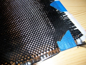
Figure 2.1.1 Example of Carbon Fibre Sheet
Carbon fibre materials are very popular among the aerospace, military, engineering, motorsports and many other industries since this material possessed certain properties. The properties are:
- High strength to weight ratio
- Fatigue resistance
- High tensile strength
- Good tolerance to the heat
- High resistance to the chemical
- The thermal expansion is low
One of the properties possessed by the carbon fibre material is that it has high ratio of strength to weight. The ratio for strength to weight of the material can be determined by dividing the value of force per unit area and the density of the material. The SI unit for strength to weight ratio is Pa m3/kg or N.m/kg. The other method to define the strength to weight ratio is to observe the length of the breaking which also known as the self support length where the longest length of vertical column that can withstand the weight of the material when it is supported at the top surface. The carbon materials that produce highest strength to weight ratio are carbon fibre and fibre glass which are usually used to make composite material. The other materials that have high specific strength that are used in aerospace industry are titanium, magnesium, aluminium and steel alloys which are light weight but expensive. (Specific strength, 2017)
| MATERIALS | STRENGTH TO WEIGHT RATIO (N) |
| Kevlar | 2514 |
| Carbon fibre | 2457 |
| Fibre glass | 1307 |
| Balsa wood | 521 |
| Steel alloy | 222 |
| Nylon | 69 |
Table 2.1.1 Strength to Weight Ratio for Specific Materials
The other important property of carbon fibre is that this material is not flammable. This property can be achieved and depends on the process during the manufacturing stage. For example, carbon fibre can be processed into soft materials and can also be processed as fire fighting clothes. The clothes used by the fire fighter are coated with the nickel fibre. The other example of carbon fibre used as fire resistance is the protective blanket which is usually used by the welder.
Moreover, carbon fibre material produces higher tensile strength value. The tensile value is also known as ultimate strength which can be described as the ability of the material to withstand certain amount of load when it is pulled or stretched before failing. The table below indicates the value of ultimate strength for some materials. (Carbon Fibre Properties, 2017)
| TYPES OF MATERIALS | ULTIMATE STRENGTH VALUES (MPa) |
| Carbon steel | 650 |
| Stainless steel | 860 |
| Aluminium alloy (2014-T6) | 483 |
| Kevlar | 2757 |
| Carbon fibre | 4127 |
| Laminated carbon fibre | 1600 |
Table 2.1.2 Ultimate Strength Value for Certain Materials
Furthermore, carbon fibre material is very rigid if it is compared to other material such as glass reinforced fibre, pine wood, aluminium and many more. The stiffness of carbon fibre is measured as 4 times larger than glass reinforced plastic and 2.5 times stiffer than aluminium. (Carbon Fibre Properties, 2017)
On the other hand, there are some disadvantages of using carbon fibre materials as the base of a structure. The first disadvantage of using this type of materials is that it needs a mould in order to create a certain shape for the carbon fibre and this requires an expert to produce the mould. Other than that, the structures that use carbon fibre as the main material will requires a lot of money since this type of material is very expensive. The other disadvantage of carbon fibre material is that it cannot be fixed. The whole carbon fibre plate need to be change if there is a tiny crack on the plate. The broken plate also needs to be thrown away since this type of material is not recyclable since it is very hard to recycle. (Solar Car monocoque, 2017)
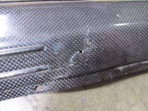
Figure 2.1.2 Cracked of Carbon Fibre Plate
2.2 FIBRE GLASS
Fibre glass is a plastic materials reinforced with the glass fibre. The glass fibre can be arranged either randomly spread on the materials surface, for example using mat of chopped strand where the fibre is flattened on a mat and arranged into fabric form. The other name for fibre glass is called Glass Reinforced Plastic (GRP) and Glass Fibre Reinforced Plastic (GFRP).
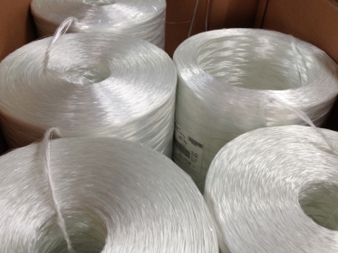
Figure 2.2.1 Sample of Fibre Glass
Most of the matrixes used with the glass fibre are epoxy, vinylexter and polyester resin. The materials which are combined with the glass fibre are depending on its application. For example, most glass fibre contains silicate can be varied by the amount of the calcium oxide. The glass fibre needs to be fabricated by the least amount of defect in order to achieve the exact characteristic and suitable for its application.
Glass fibre is very popular and being used in many different applications since this material is strong and light weight. The other characteristic of glass fibre is that it is less brittle and cheaper to fabricate compare to carbon fibre which possesses high strength and stiffness characteristics. Other than that, this type of material has better weight and bulk strength compared to other metal materials as well as being easy to mould into various shapes and designs. There are many examples of glass fibre applications used in the industries such as aircraft parts, automobiles, water tank, boats, pipes, surfboards, door skin and many more. (Fiberglass Properties, 2017)
There are lots of advantages of using glass fibre materials for a component. This can be proved by the properties of glass fibre itself. For example, glass fibre materials produce higher resistance compare to the steel in terms of the tensile strength per volume mass. The mechanical strength demonstrated by this material is the key point why glass fibre is broadly used in high performance part. Other than that, glass fibre has good electric insulator properties. These properties are applied to all thickness of the material and behave differently at different temperatures.
Fibre glass also possesses the properties of low value of thermal conductivity. Building industries prefer to use fibre glass as one of their construction material because of the materials’ low thermal conductivity. The other reason for the building industries to choose this material is that fibre glass can eliminate the thermal bridging from the structure which is also able to consider the saving heat energy. Moreover, this material is highly immune to certain chemical agents. For example, in order to create a fibre glass material with high resistance to chemical agent, an appropriate amount of resin is combined together with the glass filament which also considers what will the material be use for.
The other general properties for the glass fibre material are that it is light weight. Most of the fibre glass material is weighted about 30% lighter in weight compared to the steel parts. Even though it is 30% lighter, fibre glass material possess the same mechanical properties similar to heavy steel component. Fibre glass material is also mouldable into various type of shape. The strand of the glass helps the raw fibre glass material to be manufactured into different shapes and sizes. This includes vessel, hollow pipes, inlet manifolds, and many more. Fibre glass can also be moulded into tiny sizes such as circuit boards and electric cables. This type of material can also be considered as recyclable material by using thermoplastic and thermoset recycle process. (Fiberglass Properties, 2017)
| Fibre Type | Tensile Strength (MPa) |
Compressive Strength (MPa) |
Density (G/Cm3) |
Thermal Expansion (µm/M·°C) |
Softening T (°C) |
| E-glass | 3445 | 1080 | 2.58 | 5.4 | 846 |
| S-2 glass | 4890 | 1600 | 2.46 | 2.9 | 1056 |
Table 2.2.1 Properties for 2 Different Fibre Glass
Generally, the properties for the fibre glass material are almost the same as the material made from carbon fibre. For example, fibre glass material also immune to the certain type of chemical substance such as phosphoric acid and hydrofluoric acid. If the fibre glass material is exposed to these types of acids, the fabric texture of the fibre glass will not deteriorate. Other than that, the yarn for fibre glass is two times stronger than steel wire since this type of material produce higher ratio of strength to weight. After that, this type of material also has better thermal properties. The lower coefficient of thermal expansion is the key point for this material to minimise stretching and shrinking during the fabrication process. This is because the coefficient of thermal expansion for fibre glass material is only 5.4 by 10.6 cm/ºC. Fibre glass will also possess higher thermal of conductivity compared to other materials such as organic fibre and asbestos. This material is able to evaporate the heat in a short amount of time. The following figure shows the relationship between the thermal expansion and temperature for fibre glass material.
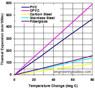
Figure 2.2.2 Relationship between Thermal Expansion and Temperature
The fibre glass material is also able to tolerate higher temperatures without causing any damage to the structure. The main advantage for this type of material is that it does not burn even when it is exposed to the flame, this made the curing process easier without the need to change the temperature setting. The fibre glass structure can retain up to 50% of its strength even if it is exposed to 700ºF of temperature. This type of material is also suitable to be used as the electric conductor since it produces higher dielectric strength as well as a lower dielectric constant. This is the reason why fibre glass is a suitable insulator for the electricity. Moreover, fibre glass material has low absorption to any surrounding moisture as it is also easy to mold into any shape without having any problem. This characteristic makes the fibre glass material more versatile after it is cured into the final product as well as being able to be molded into various sizes. However, fibre glass material offers lower cost of production compared to carbon fibre and other fibre from natural fabric. (Properties of Fiberglass Fabrics – Reinforcement/Coating/Laminating Fabrics, 2017)
2.3 SHAPE MEMORY ALLOY
Shape memory alloy is a smart material that is able to return to its original shape when the material is heated. The shape memory alloys was found by Arne Olander in 1938 and further studies related to this type of material continued in the 1960’s. The unique properties for this type of material are the effect of shape memory and pseudo-elasticity which is also elastic. This type of material mostly is used in aerospace, automotive as well as robotic sectors and is sometimes used for medical purposes. Memory shape alloy is commonly used in solid state since it is a lightweight material.
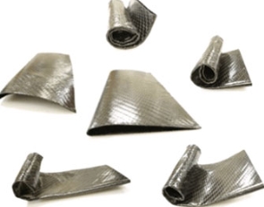
Figure 2.3.1 Example of Shape Memory Alloy Sheet
There are two types of shape memory alloys that are used in industries. The two types are Nickel Titanium based and Copper-Aluminium-Nickel (Cu-Al-Ni) based. However, shape memory alloy can also be created by using alloying process. This process usually uses gold, copper, zinc and iron as the base of the material. The copper-aluminium-nickel based shape memory alloy is the most commonly used and easy to find and it is also cheaper compared to nickel-titanium based. However, the application of NiTi based for shape memory alloy material is higher than other based type of material since nickel-titanium based material is more stable and practical as well as having better thermo mechanics. This shape memory alloy can be found in two phases which are austenite and martensite as well as able to transform into 6 different formation. (Shape Memory Alloy – Nitinol Shape Memory, 2017)
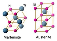
Figure 2.3.2 Two Phases for Shape Memory Alloy
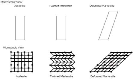
Figure 2.3.3 6 Phases of Shape Memory Alloy Deformation
The martensite phase for the shape memory alloy material occurs when the sheet of SMA is exposed to lower temperature. When the lower temperature is introduced to this type of material, the material will become softer and easily deform into the desired shape. A unique configuration of the molecule structure will deform in this phase where it is called twinned martensite. After the deformation of the molecules, the structure will experience the second phase which is referred as austenite where it is only occurs when the material is placed under higher temperature. The next formation for this material is referred as un-deformed martensite where it has no different to the austenite phase in terms of the shape and size but will change after the deformation. (Webdocs.cs.ualberta.ca, 2017)
The transformation phase for SMA material depends on the temperature change and the maximum load applied on the structure. Usually, the deformation phase from start to finish for martensite is represented by Mf and Ms while the formation for austenite are labelled as Af and As. Figure 2.3.4 shows the temperature different and loads applied to the molecules for both martensite and austenite structure of shape memory alloy. In addition, the arrangement of the wire for the structure can also affect the variables for both austenite and martensite molecules.
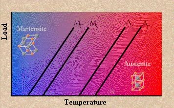
Figure 2.3.4 Deformation for Austenite and Martensite Structure
In order to observe the effect, the material needs to be set to below the Mf temperature where at this temperature the alloy can deform easily without using excessive force. The original shape of this smart alloy can be achieved by applying heat on the wire. The temperature for the recovering process needs to be higher than the temperature for Af as shown in figure above. In short, the temperature applied to the structure is the driving power for the molecules in order to return to its original shape. Therefore, the deformation of martensite will transform ino austenite cubic phase. Nowadays, there are lots of applications for this smart material. Some of the structure that use shape memory alloys are the space shuttle, hydraulic fitting on airplanes, thermostats and many more. (Webdocs.cs.ualberta.ca, 2017)
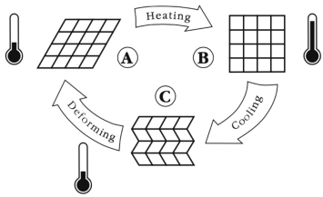
Figure 2.3.5 Actuating Shape Memory Alloy
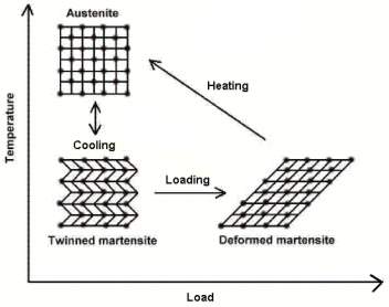
Figure 2.3.6 Microscopic Effect of Shape Memory Alloy
There are two different effects that can be observed on the shape memory alloy behaviour. The effects are referred as shape memory in one way and two way effect. The following figure 2.3.7 illustrates the different behaviour for both one way and two way effect on the materials’ memory. Generally, both effects will have to experience the same procedure but will only be different during the second stage. Both structures will start as martensite phase where the structure is in steady state without experiencing any deformation.
However on the second phase, there are slightly different methods to observe the effect of the structure. For one way memory effect, the reversible deformation is applied on the structure where the structure will start bending in a certain shape. On the other hand, a large amount of irreversible deformation is required on the two way memory effect in order to make the rod bend. After that, both rods are heated as the structure will return to its original shape and let the rod cool down.
The cold stage for shape memory alloy is always referred as the As point on the graph where the structure which is made of shape memory alloy can be bend and stretch. In this phase, the metal structure will retain the bent shape until it is introduced to the specific transition temperature. After applying the heat, the metal will return to its original shape and size until it cool down. When the metal in a cool state, it will remain in that same shape until any load is applied to the structure again.
The cooling process for one way effect will not affect the arrangement of the microscopic structure. Usually, the transformation from point As to Af will only require a temperature difference between 2 to 20ºC and this is also depends on the composition of the alloy and the condition of the loading. The point of As on the graph is varied depending on the type of alloy and its composition as well as the temperature setting from -150 ºC to 200 ºC. (Shape Memory Alloy – Nitinol Shape Memory, 2017)

Figure 2.3.7 One Way Memory Effect
Meanwhile, the two way shape memory alloy effect is able to remember two different shapes. The reason of calling this material as two ways memory effect is that it can remember both shapes during low and high temperature. The shape for this type of material can be achieved by just applying different settings of temperature without the need to apply external load on the structure. The force applied on the material can be assumed as the training so that the metal can remember the shape during cool temperature. When the heat is applied, the metal will form a new shape and ignore the previous shape during low temperature. However during the deformation from low to high temperature, the metal still leave some of the reminder from the previous low temperature deformation.

Figure 2.3.8 Two Way Memory Effect
Most of the applications for shape memory alloy are used in medical sectors which used for surgery purpose. The application for this type of material is widely used in medical sectors from dentistry up to surgeries for endovascular which related to the blood vessels operation. The shape memory alloy material can also be used in some equipment as the replacement part such as valve frames, needles, distal protection and as the tubes as a guide for endoscopic operation. (Shape Memory Alloy – Nitinol Shape Memory, 2017)
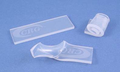
Figure 2.3.9 Sample of Shape Memory Polymer
Other than application for medical purpose, the shape memory alloy can also be used in some other industries such as for fabrication, automotive, furniture, engineering parts and many more. For example, the SMA material can be use to fabricate molds which can be used many times. This can reduce the cost of fabrication for manufacturing company. Other than that, some containers and structures can be made out of this material as well as parts for automotive industries such as cars, airplanes and many more. (Crgrp.com, 2016)
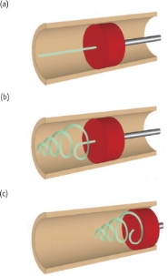
Figure 2.3.10 Application of SMA Material
2.4 MORPHING AIRCRAFT RESEARCH BY BRISTOL UNIVERSITY
From 2005 to 2008, Bristol University with the help from European Commission and Marie Curie Excellence Grant tried to look deeper into the morphing wing structure in terms of its design, the airflow through the wing surface, dynamic structure, the system of the flight control, and its sensors. The reason of looking into these areas was to determine how the shape changing design affects the load of the aerodynamic for the aircraft and its control system. During this research, Bristol University only focused on three main point of interest, these are discussed below..
The first point of interest is the effect of the active wing towards the multi axis and the concept of novel for the aerodynamics. In this aspect, the researcher tried to apply the morphing technology into the control effectors. This concept involves the features of extension wing tip and the variable dihedral angles which are also referred to as active winglets. The effectors will control the movement of the aircraft on directional, lateral and longitudinal axis. The studies were focussed on the two pairs of replaceable active winglets on the conventional control surface. The model of this study has been tested under the vortex lattice experiment and wind tunnel and the results were then compared.
The second criteria considered during the study were the effect of multi stable composite structure. In this case, the orthotropic properties can be use in large deformation of the morphing structure where the hinges can be considered to be removed in order to reduce the stress acting on the pivot points as well as will reduce the weight of the morphing design. Both cool down manufacture and snap through situation has been analysed by using the finite element analysis program in order to establish the stable equilibrium state for the structure.
The next criteria considered in this experiment was aeroelastic tailoring. Material made of laminated composite are widely used in aerospace industries since this material possess higher ratio of stiffness and strength. In order to morph the structure, the properties of elastic coupling are used as the conventional wing is produced to control the twist of the wing during the lift.
2.5 FLEXFOIL BY FLEXSYS
The FlexFoil project is a project which develops the morphing wing as an improvement for the flap wing system on the aircraft wing. The used of flaps on the aircraft wing can be considered as heavy mechanisms since the flap wing requires lots of assemblies and parts in order to trigger the flaps.
Other than that, the flap wing can also change the aerodynamics of the aircraft during the flaps deployment and can only extend up to 30º of flaps. By improving the wing design to morphing shape, the wing can control large deformation from -9º up to maximum of 40º which is very important to the aircraft during takeoff and landing period without deploying the flaps away from the wing structure. The design of morphing wing for the commercial airplane can also minimise the induce drag and it also can capable to handle loads in terms of inertial loads, air loads and many more during flight session. In addition, the morphing design is so stiff and strong so that it can evenly spread the loads and strains along the structure. (FlexSys, 2016)
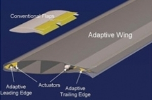
Figure 2.5.1 Control Surface for FlexSys Morphing Structure
The morphing wing for commercial airplane developed by FlexSys was the first design which can withstand any flight condition in real life. This morphing design used no hinge on the wing and seamless wing shape was funded by the US Air Force where it was successfully design and consists of proprietary control surface for the morphing wing.
The used of morphing wing structure on the commercial airplane was proofed to be fuel saving efficiency. In terms of the long range aircraft with fixed wing, the low fuel consumption was caused by reducing the drag up to 12% which can be considered as large amount of fuel saving. According to the NASA Flight Research Centre, 1% of drag reduction can save up to 200 million gallons of fuels in one year period of time. (FlexSys, 2016)
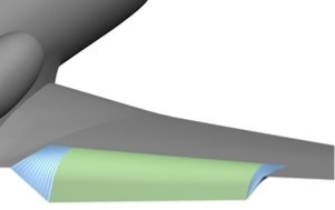
Figure 2.5.2 Control Surface Design by FlexSys
2.6 SMART MATERIAL FOR UAV PERFORMANCE BY SWANSEA UNIVERSITY
The idea for researching and developing the morphing structure for the aircraft came from the birds’ wings which are able to morph during normal flying and attacking. This morph is referred to the configuration of the wing that can twist for control during flying. The concept of morphing wing can be fit on the aircraft as the replacement of the deployable flaps which can affect the aerodynamic configuration of the aircraft when deploying the flaps. The mission for this research is to expand the effectiveness of the aircraft by exempting the requirement of multiple and expensive aircraft mission. The other mission for this study was to eliminate the substantial efforts required for the morphing structure by eliminating the aeroelastic instabilities limitation. (Swansea.ac.uk, 2016)
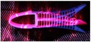
Figure 2.6.1 Concept of Morphing Design
Generally, there are some advantages of applying the morphing structure on the modern aircraft. Some of the advantages are the performance of the aircraft can be improved and it is able to extend the flight envelope. Other than that, the morphing design can also improve the control surface of the aircraft in terms of the stealth and flight performance. Lastly, the design of morphing structure can minimise the amount of drag for the aircraft at the same time can increase the flight range. In this research by Swansea University, the research area for morphing structure was mostly concern on the concept of the morphing design, its skin as well as how to model and optimise the morphing structure.
According to the researchers form Swansea University, in order to fabricate the morphing model for the airplane, there are 5 main criteria that need to be considers. The 5 criteria are the requirement of the actuations, estimation of the weight, the performance of the aircraft, the structure of the wing, the aerodynamics and the mission profile required during the development.
After completing the study area, similar model is required as the model is tested on a simulation program in order to integrate and optimise the level of the system. The researchers also used the exact model of the morphing design to calculate and determine the performance of the airplane as well as to make sure there will be no failure during flight session. The issues on this design can also be determined by using full scale model in the simulation software and performed the model verification. (Swansea.ac.uk, 2016)
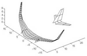
Figure 2.6.2 Optimisation of the Morphing Model
The next research area for this project was the morphing skins. The deformable skins with specific materials need to be produce for this project. The fabrication of the skins was produce by considering the aerodynamics performance of the aircraft since this type of wing need to support the loads of aerodynamics. The specific wing configuration called corrugated skins was chosen as the main design for morphing structure. This design of skin was used in the model systems as it can optimise the morphing aircraft. The configuration of morphing skin is shown in Figure 2.6.3 below.
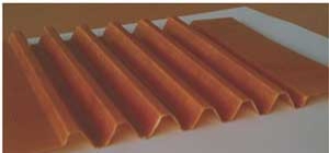
Figure 2.6.3 Corrugated Skin
Last but not least, some of the camber of the morphing wing concept was tested in wind tunnel setup in order to select the best configuration design and the best configuration was selected. The selected model was called as Fish Bone Active Camber design. This type of morphing configuration contains 4 different elements. The elements are the core of the skeleton, pre tensioned skin made from composites and matrix, pulley acting as the driving mechanisms and the main spar. This design was selected as the best configuration since it can trigger the airfoil camber into large amount of deflection. This type of wing setting also proposed as the priority design for any aircraft with fixed wing, helicopters and many more. (Swansea.ac.uk, 2016)
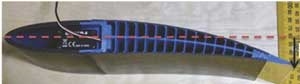
Figure 2.6.4 Morphing Camber Configuration
2.7 MORPHING WING STRUCTURES FOR CRUISE MISSILES
Raytheon Company (NYSE: RTN) is developing a revolutionary aircraft structure technology that could change in flight to adapt to mission requirements, targets and other changes in battle. Raytheon received a $4.1 million contract from the Defense Advanced Research Projects Agency (DARPA) for its work under the Morphing Aircraft Structures program. Raytheon is proposing adaptive wing technology for its cruise missile mission vehicles. Prototypes are scheduled to be tested in early 2005.
Morphing wings is the first in a series of steps to permit a cruise missile to travel at high speeds to a target area, loiter and then move to another target area, with speed changes from 0.3 Mach to 3.0 Mach. The technology ultimately could be applied to other platforms and future air vehicles, manned and unmanned.
DARPA’s Defense Sciences Office is investigating advanced concepts that use integrated design with advanced materials, actuators, sensors and electronics to create devices and adaptive structures that enable significant in-flight vehicle shape change. These shape changes are more significant than those currently found in flight vehicles, and, in turn, will enable new military capabilities such as those envisioned by Raytheon.
According to the Raytheon’s Morphing program manager, Donald Uhlir, the morphing program by Raytheon company want to present the revolution of the missile where the missile is able to perform multiple task in one time efficiently. In addition, the application of morphing applied to the missile will provide efficient flight session at different speed as altitudes without any lost of the performance when operating off the optimized cruise point. The quick response to the target and mission flexible will reduce the quantity of the missile used to destroy one single target.
Raytheon Company, with 2002 sales of $16.8 billion, is an industry leader in defense, government and commercial electronics, space, information technology, technical services, and business and special mission aircraft. With headquarters in Lexington, Mass., Raytheon employs more than 76,000 people worldwide. (Company, 2017)
CHAPTER 3
METHODOLOGY
3.1 STEP OF FABRICATION
3.1.1 DRAWING AND 3D PRINTING THE MOLD
The first step to fabricate the mold for the corrugated structure is to draw the 3 dimension drawing by using AutoCAD software. The design of the mold can be draw by selecting the poly line option on the drawing tools menu. The corrugated shape mold is divided into two different parts which can be referred as bottom and top mold. The length of the mold is 20 cm and extrude by 20 cm depth. The angle used for the corrugated shape is 60º. This is the best angle to be used for designing the corrugated shape.

Figure 3.1.1.1 2 Dimension Bottom Mold
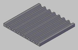
Figure 3.1.1.2 Bottom Mold in 3 Dimensions
However, the dimension for the top mold is different where the depth needs to be longer than the mold. This is because the top mold will be screwed on a piece of plywood in order to get the right corrugated shape. The depth of the top mold is measured 30 cm. After completing the drawing, the mold will be printed by using 3D printing machine since this is the easiest way to fabricate the mold compare to machining using milling machine.
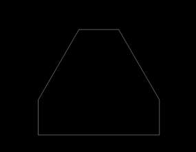
Figure 3.1.1.3 Top Mold Drawing
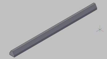
Figure 3.1.1.4 Top Mold in 3 Dimensions
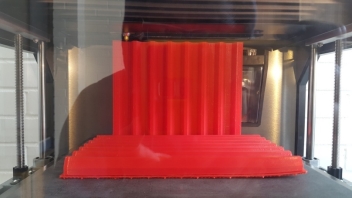
Figure 3.1.1.5 Mold Fabrication
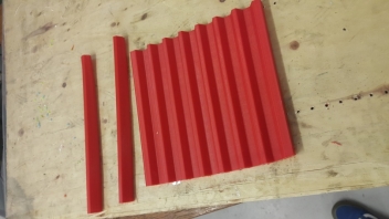
Figure 3.1.1.6 Mold Final Product
3.1.2 APPLYING WAX ON MOLD
After completing the mold fabrication, the next step to produce a corrugated carbon fibre structure is to apply the wax resin on the surface of the mold. The reason of applying is that the wax will act as the protective layer between the carbon fibre cloth and the mold so that the final result will not stick to the surface of the mold.
However, the wax application is not a compulsory procedure during the fabrication of the corrugated structure. In case of this experiment, the application of the wax is not necessary since the surface of the mold is not smooth because of the machining process. The other reasons of not applying the wax on the caster are because the carbon fibre cloth is covered by the mold release film on both surfaces.
3.1.3 APPLYING MOLD RELEASE AGENT
The next step after applying the wax is to apply the release agent on top of the surface frame. The release agent will allow the end process which de-attaching the corrugated specimen from the mold. The application of this agent will provide a better specimen without sticking to the mold. There are three types of release agent that can be use with different way of application. The three types are called PVA, styrene wax and FibRelease. (Fibre Glast, 2017)
PVA release agent also known as polyvinyl alcohol which is made from water based solution used to prevent the specimen to stick to the mold parts. There are few ways to apply this solution to the mold. The solution can be applied by using brush, spray and paint roller. The polyvinyl solution can also be used to prevent the air from the layer of specimen during curing process. It is also can be wash with water.
The second release agent is called styrene wax. The characteristic of this wax is similar to the PVA solution. However, styrene wax will appears to the surface of the specimen after curing process. In order to remove this wax from the specimen, the application of sand paper is needed after the specimen is fully cured.
The last alternative to remove the specimen from the mold is to use FibRelease wax. This wax is safe to use since it is a product made up from water based mixture. It is a readymade solvent and it can be used directly without mixing with other substance. (Fibre Glast, 2017)
For this experiment, the fabrics is covered with release films on top and bottom surface of the structure in order to make the demold process easier as well as to avoid the layers of carbon fibre fabrics from sticking to the mold.
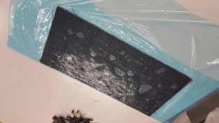
Figure 3.1.3.2 Fabrics Covered by Release Films
3.1.4 LEVELING THE MOLD
In order to get a stable and symmetry specimen, the structure of the caster need to be level and placed on the right position. The casting structure can be level by using modelling clay since it can be cast into different shape and size. The caster then can be measured by using leveller scale placed on top of the mold structure. However, the levelling procedure for this fabrication is not necessary and depends on the surface work place.
3.1.5 APPLYING EPOXY RESIN
The resin is applied between the composite cloths and on top of the specimen surface which acts as the hardener and bond the composite fabric into harder product and shinier surface. Generally, there are three types of resin commonly used for fibreglass, carbon fibre and Kevlar. The three types are known as epoxy, polyester and vinylester resins.
The first types of resins used between the composites cloth is epoxy resins. This type of resin is the most expensive hardener compared to other two resins. However, this is the strongest hardener that can be used with carbon fibre, Kevlar and fibre glass. (Sollercomposites.com, 2017)


Figure 3.1.5.1 Types of Resin and Hardener Used in the Experiment
The second type of resin is polyester resin. This type of resins is the cheapest among other two resins since it have low capability to bond the composites fabrics. This resin should not be used with Kevlar and carbon fibre fabrics because of its bonding capability. However, this resin can be use with fibre glass and it can produce a good result.
The last resin is one third of the strength compare to the epoxy type of resins. This type of resins is called vinylester resins and it is not suitable to be used with Kevlar and carbon fibre type of fabrics. Most of the fibreglass type of composite used vinylester to cure the whole structure as the main resins. However, this vinylester can be used with fibre for the application of cosmetics function as the clear coat and gel coat. (Sollercomposites.com, 2017)
The mixture of the resin need to be correct as it will affect the hardening process during the curing. The ratio of the mixtures needs to be 10:3 of the weight of the carbon fibre fabrics. In this case, the carbon fibre material is measured 108 grams as shown in figure 3.1.5.2 below. On the other hand, the measurement of the resin is approximately 80 grams while the amount of hardener used in the experiment is 26 grams.
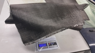
Figure 3.1.5.2 Weighting the Materials
3.1.6 PREPARING CARBON FIBRE FABRIC
For the preparation of the composite fabrics, the dimension of the mold is needed. This is because the cloths need to be cut in precise dimension so the material is not wasted. The depth of the corrugated design also need to be considers as all of the composite material cannot stretch. The estimate length of the composite cloth used for each fabrication is 30 cm and the thick is 0.3 cm. In order to achieve the desire thickness, 8 layers of material sheet is placed on top of each other at different orientation in order to make stronger bond between the materials.
Before cutting the materials, the exact dimension of the material is drawn on top of the vacuum bag plastic as shown in following figure. The reason of drawing is to make the cutting process easier after the fabric is introduced with the resin.
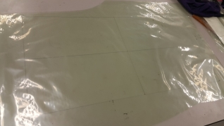
Figure 3.1.6.1 Drawing on Vacuum Bag Plastics
After that, the sheet of carbon fibre is cut slightly bigger than the exact drawing. The resin is then applied to the vacuum bag and the material is placed on between the vacuum plastic. Next, the plastic is flipped over in order to scrub the resin all over the carbon fibre fabrics. After flatten the resin, the materials is cut into eight smaller parts and layered on top of each other.
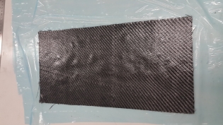
Figure 3.1.6.2 Layering the Fabrics
3.1.7 CURING THE COMPOSITE
Most of the composite structure will be cured under vacuum chamber in order to remove bubble of air from the resins between the fabrics. However, the corrugated type of composite does not need to be cure in vacuum chamber since the mold consist of two separate mold which can be tighten by using screw. During the tightening process, the bubbles of air will escape as well as the excess resin from the structure.
The top mold plays the important role since it will provide the best shape for the composite. The tighter the top mold the better the final product and loose of the top mold will provide an uneven surface for the final result and this might affect during the testing process.
During the curing process of the structure, the carbon fibre is placed on the mold and the top mold is clamped one by one since the fabric cannot stretch. After complete the clamping process, the mold is left in order to cure on its own as no need to put the structure under vacuum chamber. The curing process is illustrated in following figure.
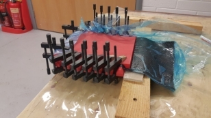
Figure 3.1.7.1 Curing Process for Corrugated Structure
3.1.8 DEMOLD THE CARBON FIBRE
Demold process is the last fabrication procedure to be done in order to get the result of the composite model. This process can be done after 24 hours of curing process or after the resins is fully cure and hard. The top parts of the mold need to be detach one by one as the top mold is screwed to secure the position. After removing all of the top molds, the corrugated model can be lifted slowly so that the model did not broken during the demold activity. After that, the model is trimmed form the excess material for a clean finishing. Lastly, the corrugated model is sprayed layers of clear coat for shiny end result. However, the application of clear coat is depend on the developers since it only for surface finishing and not for adding strength to the structure. After demolding, the specimen is cut into smaller pieces with the dimension of 40 mm × 200 mm in order to be fitted on tensile and 3 point bending test machine.
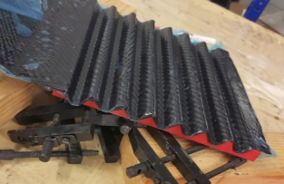
Figure 3.1.8.1 Removing Carbon Fibre from Mold
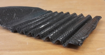
Figure 3.1.8.2 Corrugated Carbon Fibre
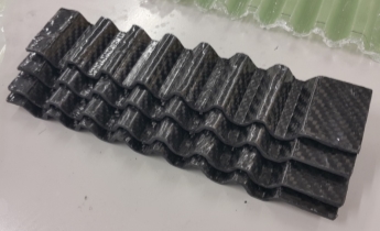
Figure 3.1.8.3 Smaller Piece of Specimen
3.2 STANDARD TESTING PROCEDURE
3.2.1 3 POINT BENDING TESTING
Bending test can be defined as the procedure to measure the properties of the materials in terms of the yield and stiffness. This test can also be perform in order to determine the ability of the material to withstand the stress applied on top of the surface before the material break. Other than that, the bending testing can also determined the tensile strength value for the materials. There are lots of types of materials that can be tested by using bending test. Some of the materials are listed on the following list: (Corrosionpedia, 2017)
- Polymers
- Woods
- Composites
- Brittle materials
- Dry wall
- Ceramic tiles
- Metal
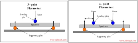
Figure 3.2.1.1 Illustration for 3 and 4 Point Bending Test
There are two types of bending testing that can be perform on these types of material. The two types are called 3 point and 4 point bending testing. The differences for both types of bending testing are shown in table 3.1.2.1. (Pratt, 2017)
Both ASTM and ISO standard operating procedure can be used to test the material by using 3 point bending test. The standard that covers the procedure for this type of testing is called ASTM D790 and ASO 178. Basically, the specimen of the material is placed on top of the support span which then the force is applied at the middle of the specimen. During the testing, the following component can be manipulated in order to simulate the real environment situation. The parameters are loading speed and maximum deflection of the material. The adjustment of the parameter is depended on the thickness of the specimen. According to ASTM D790, the test is carried out until the material reach the 5% of deflection while ISO 178 standard carried out the test until the material break.
The different of these standards are for the size of the material. The size of the material that can be tested by using ASTM D790 is 3.2 mm × 12.7 mm × 125 mm. Meanwhile for the ISO 178, the size of material needs to be measure 10 mm × 4 mm × 80 mm in order to carry out the testing process. (Ptli.com, 2017)
| 3 Point Bending | 4 Point Bending |
|
|
Table 3.2.1.1 Comparison between 3 and 4 Point Bending
3.2.2 TENSILE TEST
Tensile testing is an experiment on the material in order to evaluate the performance of the materials regarding on the suitability material for engineering purposes as well as to be used in construction application which will ensure the quality of the structure. (Corrosionpedia, 2017)
It can also be referred as tension testing where the test is carried out within controlled variable until the specimen fails. Usually, the result of tensile test is obtained in order to make a selection of specific material for an application. Other than that, the result from tensile testing can be used to control the quality of the structure as well as to determine the reaction of the material towards forces applied on the specimen. Some peroperties can be obtained by performing the tensile testing on the materials. The properties are elongation of the material, ultimate tensile strength and the decreasing area of the specimen. By obtaining these properties of the specific specimens, the Poisson’s ratio and Young’s modulus of the material can be acquired. In addition, the value for yield strength of the material can be calculated as well as the characteristic of the strain hardening can be established.
However, the most common tensile machine used to determine the mechanical properties of an isotropic material is called Uniaxial tensile machine. An isotropic material can be defined as the material that possessed the same values in terms of its properties in all directions. Meanwhile, biaxial tensile testing machine can be used to examine the anisotropic material where the value of Young modulus for the material changes with direction throughout the materials. (Corrosionpedia, 2017)
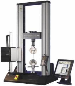
Figure 3.2.2.1 Uniaxial Tensile Machine
The most common standard operating procedure for testing the composite structure is known as ASTM D3039. This testing standard can be used to any dry reinforced composites. Generally, this type of testing is performed in order to measure the required forces for breaking, stretching and elongating the composite specimens. The result of tensile testing is plotted under stress-strain graph which then the tensile strength can be gained. The outcome of the testing is used to determine the characteristic of certain material which then can be sort into its application. Other than that, it can also be used as the quality control check list for the material. In addition, some of the material is tested under high and low setting temperature in order to simulate different environment condition.
Commonly, a uniform specimen size is tested by using ASTM D3039 is a rectangular specimen with the dimension of 25 mm × 250 mm and tested under room temperature condition. This specimen are gripped and pulled until it breaks which the data is recorded. (Intertek.com, 2017)
CHAPTER 4
RESULT AND DISCUSSION
4.1 RESULTS FOR CARBON FIBRE
4.1.1 EXPERIMENTAL RESULT FOR BENDING TEST
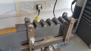
Figure 4.1.1.1 Specimen Placed on 3 Point Bending Test
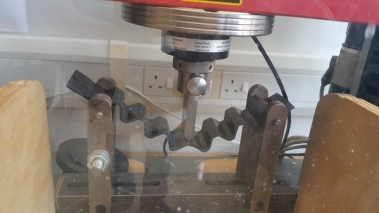
Figure 4.1.1.2 Carbon Fibre Specimen under Testing
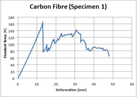
Figure 4.1.1.3 Maximum Deflection for Carbon Fibre
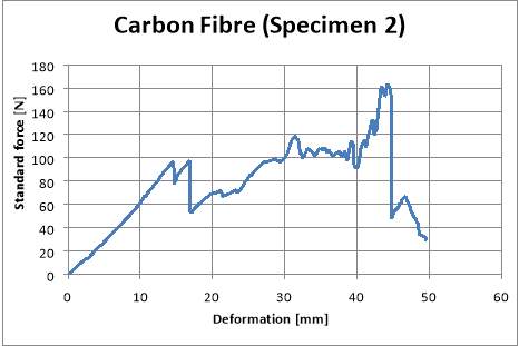
Figure 4.1.1.4 Deformation on Specimen 2 Carbon Fibre
4.1.2 THEORETICAL COMPARISON
NORMAL STRESS
Stress , σ =Force (F)Area (A)
Stress , σ = 2.89×10³ N108.10×10-3 m
Stress , σ =26.734×10³ N/m2
4.1.3 EXPERIMENTAL RESULT FOR TENSILE TESTING
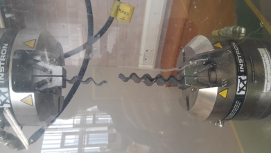
Figure 4.1.3.1 Carbon Fibre Specimen on Tensile Test
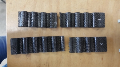
Figure 4.1.3.2 Broken Pieces of Carbon Fibre
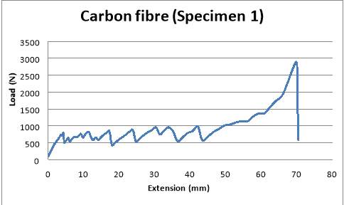
Figure 4.1.3.3 Curve for Specimen 1
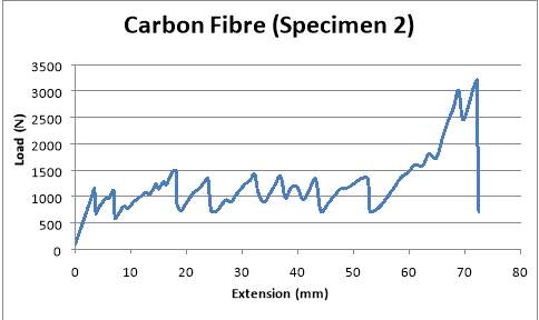
Figure 4.1.3.4 Extension for Carbon Fibre Specimen 2
| Sample | Area
(mm2) |
Load at break (kN) | Max. Load (kN) | Load at yield (kN) | Tensile stress (MPa) | Young’s Modulus (MPa) |
| 1 | 108.10 | 2.89 | 2.89 | 2.87 | 27 | 329.30 |
| 2 | 120.00 | 3.21 | 3.21 | 1.05 | 9 | 619.84 |
Table 4.1.3.1 Tested Carbon Fibre Properties
| Sample | Max Tensile Stress (MPa) |
| Specimen 1 | 26.77 |
| Specimen 2 | 26.72 |
Table 4.1.3.2 Maximum Tensile for Carbon Fibre Specimen
4.1.4 THEORETICAL COMPARISON FOR TENSILE TESTING
NORMAL STRAIN
Strain , ε = Change in Length (ΔL)Original Length (L)
Strain , ε = 2257.84-187 187
Strain , ε =11.074
MODULUS OF ELASTICITY
Modulus of Elasticity , E = Stress (σ)Strain (ε)
Modulus of Elasticity , E =26.734×10³ N/m211.074
Modulus of Elasticity , E =2.414×10³ N/m2
4.2 RESULTS FOR FIBRE GLASS
4.2.1 EXPERIMENTAL RESULT FOR BENDING TEST
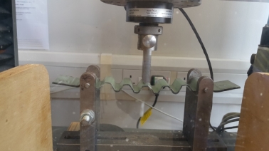
Figure 4.2.1.1 Testing Glass Fibre Specimen
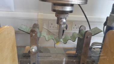
Figure 4.2.1.2 Bending the Glass Fibre
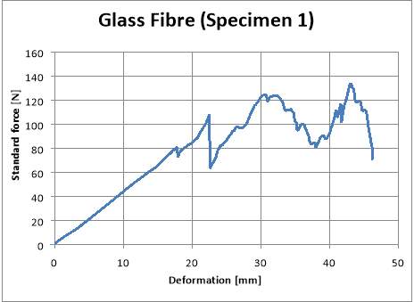
Figure 4.2.1.3 Deformation for Fibre Glass
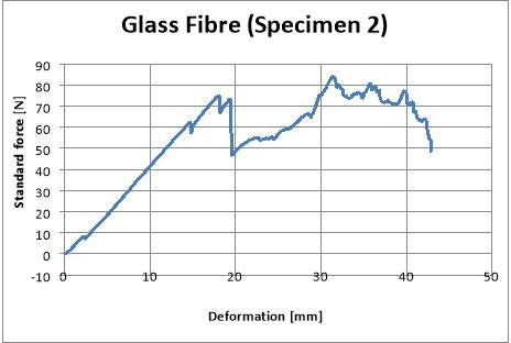
Figure 4.2.1.4 Glass Fibre Bending Curve
4.2.2 THEORETICAL COMPARISON
NORMAL STRESS
Stress , σ =Force (F)Area (A)
Stress , σ = 5.03×10³ N120×10-3 m
Stress , σ =41.92×10³ N/m2
4.2.3 EXPERIMENTAL RESULT FOR TENSILE TESTING
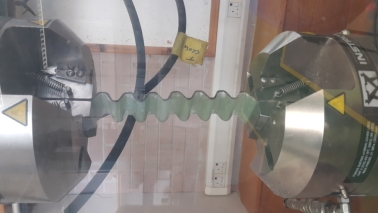
Figure 4.2.3.1 Fibre Glass Specimen on Tensile Test Machine
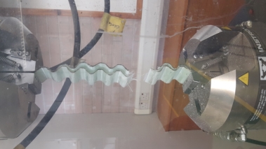
Figure 4.2.3.2 Failure on Fibre Glass Specimen
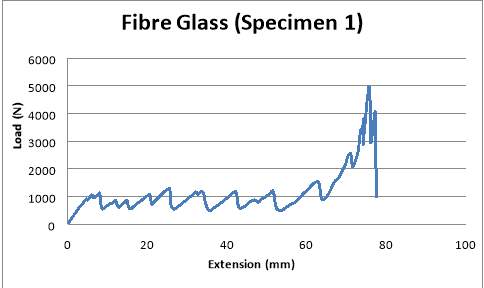
Figure 4.2.3.3 Extension for Fibre Glass Specimen 1
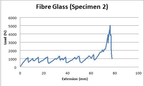
Figure 4.2.3.4 Specimen 2 Extension Curve
| Sample | Area
(mm2) |
Load at break (kN) | Max. Load (kN) | Load at yield (kN) | Tensile stress (MPa) | Young’s Modulus (MPa) |
| 1 | 120.00 | 4.07 | 5.03 | 0.91 | 8 | 412.40 |
| 2 | 120.00 | 3.31 | 5.07 | 1.05 | 9 | 394.62 |
Table 4.2.3.1 Properties for Fibre Glass
| Sample | Max Tensile Stress (MPa) |
| Specimen 1 | 41.94 |
| Specimen 2 | 42.28 |
Table 4.2.3.2 Maximum Tensile stress for Fibre Glass
4.2.4 THEORETICAL COMPARISON FOR TENSILE TESTING
NORMAL STRAIN
Strain , ε = Change in Length (ΔL)Original Length (L)
Strain , ε =75.88187
Strain , ε =405.77 × 10⁻³
MODULUS OF ELASTICITY
Modulus of Elasticity , E = Stress (σ)Strain (ε)
Modulus of Elasticity , E =41.92×10³ 405.77× 10⁻³
Modulus of Elasticity , E =103.31× 10³ N/m2
4.3 DISCUSSION
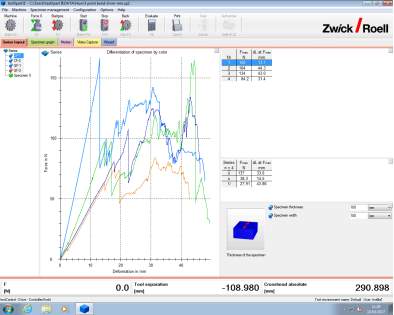
Figure 4.3.1 Comparison of 4 Different Specimens
After completing both tensile and 3 point bending test, the result of each test is compare in order to identify the characteristics of fibre glass and carbon fibre. Generally, all results gained from both carbon fibre and fibre glass illustrates almost the same behaviour since the corrugated shape design is produce by using the same process. The result obtained during the experiment can be compare and proof by doing theoretical calculation regarding on the obtained data from the experiment. The experiment can be considered as successful because the result produces by theoretical calculation are almost the same as the experimental value.
The defection graph for specimen 1 carbon fibre shows the amount of 166 N which is the highest force applied to the specimen. At this moment, the bending of the specimen is 13.1 mm from the original position. For the second specimen of carbon fibre, the maximum load applied at the middle of the material is 164 N which is slightly less than the first specimen. The second specimen of carbon fibre shows the highest change in the length during the deflection test at 44.3 mm. The huge gap of deflection illustrate by both carbon fibre specimen might be because of the curing process for the material since the mold is not tightly clamped and there are flaws on the surface of the material which might affect the performance of the materials.
In terms of the fibre glass specimen, the largest amount of force used before the material breaks is 134 N and the maximum deflection at the highest point of force if 43 mm. Meanwhile, the second specimen is able to tolerate only 84.2 N of force before the failure of the specimen. Before the material breaks, the highest deflection recorded on the testing machine is 31.4 mm where it is slightly decrease compare to the first specimen. Compare to the carbon fibre, the fibre glass is fabricated with almost no flaws on the surface of the material and the mold is tightly clamped during the fabrication process.
During the 3 point bending test, the variable is controlled in order to generate accurate result. The controlled variables are the speed of the applied force and the size of the tested material. The speed of the applied force is constant for both carbon fibre and fibre glass specimen at 25 mm per minutes. Other than that, all four specimens are cut into same dimension of 40 mm width in order to fit on the simply supported jaw in 3 point bending machine.
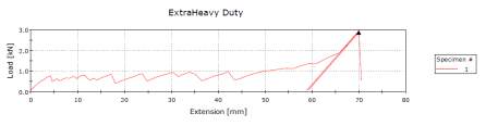
Figure 4.3.2 Example of Tensile Testing Result
In terms of the tensile testing for the specimens, the graph illustrates the incline and decline pattern at the middle of the graph. This is because of the design of corrugated specimen where the corrugated part break and stretch into straight fibre glass sheets of material. This behaviour is observed for both types of specimens since the tensile machine pull the corrugated design of the material before the materials failed. The trend change at the end part of the graph where the data is escalated to the highest point at 2893.4 N of force and the material stretched up until 70 mm from the original length.
During the tensile testing of the material, the speed of pulling the specimen is varied for each specimen in order to generate the most accurate curve for the graph. For the first specimen of carbon fibre, the pilling speed is 20 kN per minutes. The high speed of pulling the material provides rough pattern of graph since the corrugated design on the material break into a straight sheet of material before breaking. The pulling speed for the second specimen of carbon fibre is half of the first specimen at 10 kN while both fibre glass specimen is pulled by using same speed at 5 kN per minutes.
CHAPTER 5
CONCLUSION
5.1 CONCLUSION
As the conclusion, the experiment is successfully performed within the given time frame. The application of composite corrugated structure can be found in aircraft under the skin of the wing. By doing this research on the properties of the composite corrugated, the limitation of the material can be observed such as the effect of tensile force on the type of material and its shapes. For example, the tensile and 3 point bending testing will provide the properties of maximum load, tensile stress at maximum applied load, Young’s modulus, as well as stress and strain of the material.
In order to observe more properties, the material needs to be tested under many types of testing procedure rather than only performing two types of testing. The other testing that can be use to know the properties of the material are impact testing, hardness test, fastening test, fatigue test, finite element testing as well as moisture effect for the material and many more.
Because of the material is tested using two types of testing, there might be some error on the properties of the material gained from this experiment. However, there are some recommendations for future reference regarding on the process to test and fabrication of the material. The recommendation is listed in the following section.
5.2 RECOMMENDATION
After completing all test using 4 specimens, the following finding is observed through the result. The test result for 3 point bending test is not consistence and illustrate huge gap between test 1 and 2 for carbon fibre specimen. This might be because of the uneven application of the resin during the fabrication of the material. the application of resin need to be spread evenly so that the material can stick together without any air bubble in the middle of the specimen which can provide faulty to the experimental result.
In addition, in order to gain more precise data during the experiment, the speed of the applied load to the material need to be constant. For example, during the experiment, the speed of applied load is change for each specimen. During the tensile test, the first specimen of carbon fibre is testes by using the speed of 20 kN/min. For the second specimen of carbon fibre, the speed of applied load is reduced to 10 kN/min. The most stable graph can be observed on fibre glass curve where the applied load is reduced to 5 kN/min where the specimen takes longer time to reach its breaking point. During the 3 point bending testing, the speed of applied load is constant at 25 mm of deflection per minutes.
However, there are some parts of the experiment that need to be considered in order to obtain an accurate finding. The first suggestion to fabricate the material in short period of time is to fabricate more than one mold. This is because the material required almost 30 hours of time to cure the material in room temperature of 20ºC. The fabrication of the material can be reduced by half if more than one mold is used during the fabrication which the material can be cure at the same time.
The second suggestion in order to enhance the result is to use a precise dimension mold. In this experiment, the mold used by the student is not symmetrical due to the 3D printing process. The uneven dimension of the mold will produce unbalance corrugated shape where it will affect the result during the testing. The final product of the material produce by faulty mold is not a good material to test since the probability to have inconsistence result is higher.
Other than that, the composite specimen needs to have at least 50 mm of extra material at both end of the specimen. The excess material off the mold is used during the tensile testing period where the both end will be placed on the jaw to provide more grip to the material. The smaller area of the material grip by the jaw can lead to failure during the testing where the material will came out of the gripper jaw and might break the specimen.
The next suggestion for this experiment is to cut the specimen into precise sizes where it can be fitted on specific machine. For example, the size of specimen required for 3 point bending test is less than 40 mm and 50 mm for tensile test. This specific size of specimen is stated under the standard operating procedure as it is a standard size for the testing machine.
Lastly, in order to get better characteristic of certain material, it is necessary to test the material with more than 2 type of testing methods. For example, instead of testing the material with only two testing, the material can also be tested using deflection testing methods where the material is clamped at one end and applying forces at the other end. By performing this method of testing, direct stiffness can be calculated by using Macaulay’s method as well as the Euler-Bernoulli equation can be applied during the experiment.
REFERENCES
- Crgrp.com. (2016). Morphing Systems | Cornerstone Research Group, Inc.. [online] Available at: http://www.crgrp.com/rd-center/morphing-systems [Accessed 15 Oct. 2016].
- FlexSys. (2016). FlexFoil. [online] Available at: http://www.flxsys.com/flexfoil/ [Accessed 15 Oct. 2016].
- Swansea.ac.uk. (2016). Morphing Aircraft. [online] Available at: http://www.swansea.ac.uk/engineering/research/areas/morphing-aircraft/ [Accessed 15 Oct. 2016].
- A2srl.engin.umich.edu. (2016). Wing Morphing – A2SRL. [online] Available at: http://a2srl.engin.umich.edu/research/morphing.html [Accessed 15 Oct. 2016].
- Crgrp.com. (2016). Shape Memory Polymers | Cornerstone Research Group, Inc.. [online] Available at: http://www.crgrp.com/rd-center/shape-memory-polymers [Accessed 28 Oct. 2016].
- Sciencedirect.com. (2016). Shape-memory polymers. [online] Available at: http://www.sciencedirect.com/science/article/pii/S1369702107700470 [Accessed 28 Oct. 2016].
- Science, L. (2016). Morphing Wings Are 1st Step Toward Bird-Like Aircraft. [online] Live Science. Available at: http://www.livescience.com/56838-morphing-wings-bird-like-aircraft.html [Accessed 14 Nov. 2016].
- Collins, K. (2016). Nasa successfully tests shapeshifting aircraft wings. [online] WIRED UK. Available at: http://www.wired.co.uk/article/nasa-morphing-airc [Accessed 14 Nov. 2016].
- Wright-brothers.org. (2016). The Wright Story. [online] Available at: http://www.wright-brothers.org/History_Wing/Wright_Story/Wright_Story_Intro/Wright_Story_Intro.htm#top [Accessed 19 Nov. 2016].
- Wright-brothers.org. (2016). The Century Before. [online] Available at: http://www.wright-brothers.org/History_Wing/History_of_the_Airplane/Century_Before/Century_Before_Intro/Century_Before_Intro.htm [Accessed 19 Nov. 2016].
- Encyclopedia Britannica. (2016). history of flight – Construction of the sustaining wings: the problem of lift | aviation. [online] Available at: https://www.britannica.com/technology/history-of-flight/Construction-of-the-sustaining-wings-the-problem-of-lift [Accessed 19 Nov. 2016].
- Spampinato, A. (2016). The Materials Used in the Design of Aircraft Wings. [online] AZoM.com. Available at: http://www.azom.com/article.aspx?ArticleID=12117 [Accessed 20 Nov. 2016].
- Spampinato, A. (2016). The Materials Used in the Design of Aircraft Wings. [online] AZoM.com. Available at: http://www.azom.com/article.aspx?ArticleID=12117 [Accessed 20 Nov. 2016].
- Explain that Stuff. (2016). Composites and laminates. [online] Available at: http://www.explainthatstuff.com/composites.html [Accessed 3 Dec. 2016].
- Substech.com. (2016). Polymer Matrix Composites (introduction) [SubsTech]. [online] Available at: http://www.substech.com/dokuwiki/doku.php?id=polymer_matrix_composites_introduction [Accessed 3 Dec. 2016].
- Slideshare.net. (2016). REINFORCED POLYMERIC COMPOSITE (RPC) MATERIALS. [online] Available at: http://www.slideshare.net/SAMEER19592/seminar-prestn-composites [Accessed 3 Dec. 2016].
- Association, C. (2016). Polymer Matrix Composites – Typical Properties of Fibre Reinforced Plastics. [online] AZoM.com. Available at: http://www.azom.com/article.aspx?ArticleID=1453 [Accessed 3 Dec. 2016].
- Tms.org. (2016). Metal-Matrix Composites for Space Applications. [online] Available at: http://www.tms.org/pubs/journals/jom/0104/rawal-0104.html [Accessed 21 Dec. 2016].
- Machinedesign.com. (2016). Metal-Matrix Composites. [online] Available at: http://machinedesign.com/basics-design/metal-matrix-composites [Accessed 22 Dec. 2016].
- Freitag, G. (2016). A Primer On Ceramic Matrix Composites | Composites Manufacturing Magazine. [online] Composites Manufacturing Magazine. Available at: http://compositesmanufacturingmagazine.com/2015/02/a-primer-on-ceramic-matrix-composites/ [Accessed 22 Dec. 2016].
- AZoM.com. (2016). Composite Matrix Materials. [online] Available at: http://www.azom.com/article.aspx?ArticleID=9814 [Accessed 22 Dec. 2016].
- Virial.ru. (2016). Ceramic Matrix Composites (CMC). [online] Available at: http://www.virial.ru/en/materials/201/ [Accessed 22 Dec. 2016].
- Sciencedirect.com. (2016). The mechanics of composite corrugated structures: A review with applications in morphing aircraft. [online] Available at: http://www.sciencedirect.com/science/article/pii/S0263822315006455 [Accessed 25 Dec. 2016].
- Michael.friswell.com. (2017). Morphing Aircraft at Swansea. [online] Available at: http://michael.friswell.com/morphing_com/morphing_noframe.html [Accessed 4 Jan. 2017].
- Bristol.ac.uk. (2017). Intelligent structures | Advanced Composites Centre for Innovation and Science | University of Bristol. [online] Available at: http://www.bristol.ac.uk/composites/research/intelligent-structures/ [Accessed 5 Jan. 2017].
- Carbon Fiber Properties. (2017). [online] Christinedemerchant.com. Available at: http://www.christinedemerchant.com/carboncharacteristics.html [Accessed 7 Jan. 2017].
- Fiberglass Properties. (2017). [online] Vetrotextextiles.com. Available at: http://www.vetrotextextiles.com/technologies/fiberglass-manufacturing/fiberglass-properties [Accessed 7 Jan. 2017].
- Properties of Fiberglass Fabrics – Reinforcement/Coating/Laminating Fabrics. (2017). [online] Lewcospecialtyproducts.com. Available at: http://www.lewcospecialtyproducts.com/reinforcement-fabrics/Properties-of-Fiberglass-Fabrics [Accessed 7 Jan. 2017].
- Shape Memory Alloy – Nitinol Shape Memory. (2017). [online] Jmmedical.com. Available at: http://jmmedical.com/nitinol/27072/Shape-Memory.html [Accessed 7 Jan. 2017].
- Essentialchemicalindustry.org. (2017). Composites. [online] Available at: http://www.essentialchemicalindustry.org/materials-and-applications/composites.html [Accessed 8 Jan. 2017].
- Compositesuk.co.uk. (2017). Introduction | Composites UK. [online] Available at: https://compositesuk.co.uk/composite-materials/introduction [Accessed 8 Jan. 2017].
- Johnson, T. (2017). What Is a Composite?. [online] About.com Money. Available at: http://composite.about.com/od/aboutcompositesplastics/a/What-Is-A-Composite.htm [Accessed 8 Jan. 2017].
- Explain that Stuff. (2017). Composites and laminates. [online] Available at: http://www.explainthatstuff.com/composites.html [Accessed 8 Jan. 2017].
- Mech.utah.edu. (2017). Composite Materials. [online] Available at: http://www.mech.utah.edu/~rusmeeha/labNotes/composites.html [Accessed 8 Jan. 2017].
- Kennedy, D. and Kennedy, D. (2017). Types of Composite Materials | eHow. [online] eHow. Available at: http://www.ehow.com/about_5868282_types-composite-materials.html [Accessed 8 Jan. 2017].
- Machinedesign.com. (2017). Metal-Matrix Composites. [online] Available at: http://machinedesign.com/basics-design/metal-matrix-composites [Accessed 8 Jan. 2017].
- Encyclopedia Britannica. (2017). aerospace industry – Industry processes. [online] Available at: https://www.britannica.com/topic/aerospace-industry/Industry-processes#ref753832 [Accessed 8 Jan. 2017].
- Imperialinnovations.co.uk. (2017). Smart Morphing Structures with Full Shape Control – Imperial Innovations. [online] Available at: http://www.imperialinnovations.co.uk/license/available-technologies/smart-morphing-structures-full-shape-control/ [Accessed 8 Jan. 2017].
- Slideshare.net. (2017). Smart intelligent aircraft structures. [online] Available at: http://www.slideshare.net/vikalpdongre/smart-intelligent-aircraft-structures [Accessed 8 Jan. 2017].
- Office, D. (2017). A new twist on airplane wing design. [online] MIT News. Available at: http://news.mit.edu/2016/morphing-airplane-wing-design-1103 [Accessed 8 Jan. 2017].
- Stewart, J. (2017). NASA and MIT Are Working on Mighty Morphing Plane Wings. [online] WIRED. Available at: https://www.wired.com/2016/11/nasas-mighty-morphing-wings-make-efficient-flying/ [Accessed 8 Jan. 2017].
- Substech.com. (2017). Solid state fabrication of Metal Matrix Composites [SubsTech]. [online] Available at: http://www.substech.com/dokuwiki/doku.php?id=solid_state_fabrication_of_metal_matrix_composites [Accessed 8 Jan. 2017].
- Ae.iitkgp.ernet.in. (2017). COMPOSITE MATERIALS AND STRUCTURES. [online] Available at: http://www.ae.iitkgp.ernet.in/ebooks/chapter3.html [Accessed 8 Jan. 2017].
- Msm.cam.ac.uk. (2017). Diffusion Bonding. [online] Available at: http://www.msm.cam.ac.uk/phase-trans/2005/Amir/bond.html [Accessed 8 Jan. 2017].
- Company, R. (2017). Raytheon Developing Morphing Wing Structures for Cruise Missiles. [online] Prnewswire.com. Available at: http://www.prnewswire.com/news-releases/raytheon-developing-morphing-wing-structures-for-cruise-missiles-70903472.html [Accessed 24 Jan. 2017].
- Carbon fibers. (2017). [online] En.wikipedia.org. Available at: https://en.wikipedia.org/wiki/Carbon_fibers [Accessed 25 Jan. 2017].
- Specific strength. (2017). [online] En.wikipedia.org. Available at: https://en.wikipedia.org/wiki/Specific_strength [Accessed 1 Feb. 2017].
- Solar Car monocoque. (2017). Disadvantages of carbon fiber. [online] Available at: https://solarcarmonocoque.wordpress.com/2014/03/23/disadvantages-of-carbon-fiber/ [Accessed 13 Feb. 2017].
- Appliancedesign.com. (2017). Shape Memory Alloys: New Ways of Using Heat for a Technology Advantage. [online] Available at: http://www.appliancedesign.com/articles/94706-shape-memory-alloys-new-ways-of-using-heat-for-a-technology-advantage [Accessed 15 Feb. 2017].
- Webdocs.cs.ualberta.ca. (2017). Shape Memory Alloys. [online] Available at: https://webdocs.cs.ualberta.ca/~database/MEMS/sma_mems/sma.html [Accessed 15 Feb. 2017].
- Fibre Glast. (2017). Learning Center – Mold Construction. [online] Available at: http://www.fibreglast.com/product/mold-construction/Learning_Center [Accessed 22 Feb. 2017].
- Sollercomposites.com. (2017). fabricchoice. [online] Available at: http://www.sollercomposites.com/epoxyresinchoice.html [Accessed 25 Feb. 2017].
- Corrosionpedia. (2017). What is a Bending Test? – Definition from Corrosionpedia. [online] Available at: https://www.corrosionpedia.com/definition/1459/bending-test [Accessed 8 Mar. 2017].
- Ametektest.com. (2017). Bending / Flexural Testing. [online] Available at: http://www.ametektest.com/learningzone/testtypes/bending-flexural-testing [Accessed 8 Mar. 2017].
- Instron.co.uk. (2017). Instron Flexure Test – Instron. [online] Available at: http://www.instron.co.uk/en-gb/our-company/library/test-types/flexure-test [Accessed 8 Mar. 2017].
- Types, T. (2017). Bend Test. [online] Testresources.net. Available at: http://www.testresources.net/applications/test-types/bend-test/ [Accessed 8 Mar. 2017].
- Pratt, Z. (2017). Differences between Three Point and Four Point Bending Tests. [online] Testresources.net. Available at: http://www.testresources.net/blog/what-are-the-differences-between-3-point-and-4-point-bending-test/ [Accessed 8 Mar. 2017].
- En.wikipedia.org. (2017). Tensile testing. [online] Available at: https://en.wikipedia.org/wiki/Tensile_testing [Accessed 8 Mar. 2017].
- Corrosionpedia. (2017). What is a Tensile Test? – Definition from Corrosionpedia. [online] Available at: https://www.corrosionpedia.com/definition/6239/tensile-test [Accessed 8 Mar. 2017].
- Intertek.com. (2017). Tensile Testing Composite ASTM D3039. [online] Available at: http://www.intertek.com/polymers/tensile-testing/matrix-composite/ [Accessed 9 Mar. 2017].
- Ptli.com. (2017). Flexural Test ASTM D790 ISO 178. [online] Available at: http://www.ptli.com/testlopedia/tests/flex-d790.asp [Accessed 11 Mar. 2017].
Cite This Work
To export a reference to this article please select a referencing stye below:
Related Services
View all


Related Content
All TagsContent relating to: "Sciences"
Sciences covers multiple areas of science, including Biology, Chemistry, Physics, and many other disciplines.
Related Articles

DMCA / Removal Request
If you are the original writer of this dissertation and no longer wish to have your work published on the UKDiss.com website then please: