The Use of Recycled Material in Concrete
Info: 29308 words (117 pages) Dissertation
Published: 28th Jan 2022
1.0 Executive Summary
The aim of this project was to look at the use of recycled materials in concrete mix designs. This report gives a detailed insight into the mix design and pouring process of a standard concrete mix and adapts this method for use for recycled aggregate mixes. Different types of aggregate substitutes were looked at as a possible replacement for virgin aggregate and research was carried out to see if it is possible to reduce the amount of natural virgin aggregate used in the construction industry. The financial and environmental advantages/disadvantages associated with this were also explored.
This project looked at the structural requirements of concrete in accordance with the Eurocodes and examined the characteristics of a number of different substitutes. The main type of recycled aggregate investigated in this project was recycled concrete rubble which was sourced from Belgard in Dublin. The material undertook an extensive process of refining, breaking down into smaller particles and sieving to ensure suitable usage in a concrete mix. The recycled concrete aggregate was looked at in relation to its consistency and a sieve analysis was calculated based on the results.
Practical research was carried out into the characteristics of C20 concrete mixes and forty-eight cubes were designed and crushed at 7,14 and 28 days to establish which variation of recycled aggregate would provide the most compressive strength. Research was also carried out into the use of Ground Granulated Blast Furnace Slag (GGBS) in mixes. Measures were taken to look at the carbon footprint of this project and how the reduction in carbon footprint can be attributed to the usage of recycled material.
The sustainability of projects were examined through BREEAM guidelines and how the influence of recycled material within a development positively benefits its BREEAM rating. An insight into the possible incentives for the use of recycled aggregate was also looked at such as tax on virgin aggregate and the effect this would have on the use of the material.
The possible use of demolished material from Pairc Uí Chaoimh’s redevelopment was investigated and the carbon footprint for the Marina Park development was also calculated. It was established through investigation that it was possible to use recycled aggregate in the form of crushed rubble to make a C20 concrete for low load bearing surfaces. Information obtained from this project was then applied to the new development.
Table of Contents
Click to expand Table of Contents
1.0 Executive Summary
2.0 Introduction
3.0 Concrete
3.1 History of Concrete-Making
3.1.1 Super Structures built using Portland cement
3.2 What is a concrete aggregate?
3.3 Recycled Aggregates
3.4 Importance of aggregates in concrete
3.5 The use of recycled material in concrete
3.6 Recycled Concrete
3.7 Characteristics of Recycled Aggregate in the Eurocodes
3.7.1 Compressive strength
3.7.2 High early strength
3.7.3 Working life
3.7.4 Exposure class
3.7.5 Minimising cracking
3.7.6 Aesthetic Considerations
4.0 Sustainability
4.1 What is sustainability?
4.3 The use of materials with recycled content
4.4 BREEAM
4.4.1 What is BREEAM?
4.4.2 Quality Assurance and Governance
4.4.3 Categories focused on by BREEAM
4.4.4 BREEAM Scoring System
4.4.5 Criteria for BREEAM waste category
4.4.6 BREEAM across the globe
4.5 Embodied energy
4.6 Sustainability of Concrete
4.7 Case Study – (Cement Roadstone Holdings – CRH)
5.0 Concrete Mixing Handbook
5.1 The basics of making a standard concrete mix
5.2 Slump test
5.3 Science of Concrete-Making
6.0 Concrete Cube Making
6.1 Why concrete testing is carried out
6.2 Samples used during testing
6.2.1 Cement
6.2.2 Aggregates
6.2.3 Testing of hardened concrete
6.3 Test cubes
6.3.1 Curing of Test cubes
6.3.2 Testing of cubes
7.0 Concrete cube making Procedure
7.1 Introduction to Recycled Aggregate
7.2 Aggregate refining and sieving
7.3 Aggregate Crushing Process
7.4 Mixing process
7.4.1 Mix design Ratios
7.5 Mix method
7.6 The mixing process.
7.7 Slump test
7.8 Cube Filling
7.9 Cube testing
7.9.1 Crushing Process
8.0 Results Interpolation
8.1 Mix Design 1
8.2 Mix Design 2
8.3 Mix Design 3
8.4 Mix Design 4
8.5 Mix Design 5
8.6 Mix Design 6
8.7 Mix Design 7
8.8 Mix Design 8
8.9 Results Summary
9.0 Pairc Uí Chaoimh Concrete Take-Off
9.1 Recommendations for Pairc Uí Chaoimh
10.0 Conclusion
11.0 Bibliography
Referencing of Images
Appendix A (Aggregate Mix Design)
Appendix B (Crushed Cube Cores)
Appendix C (Pairc Uí Chaoimh)
Appendix D (Risk Assessment and Method Statement)
Index of Tables
Table 1 - Grading of aggregates
Table 2 - Compressive Strength classes
Table 3 - Working life of a structure
Table 4 – Exposure Class
Table 5 - Category Weighting System
Table 6 – Distribution of Aggregate
Table 7- % Breakdown of Aggregate
Table 8 - Mix Designs Breakdown
Table 9 - Mix Design Ratios
Table 10 - Mix Design Ratios
Table 11 - 50% OPC & 50% GGBS Mix Design Ratios
Table 12 - Slump Test Results
Table 13 - Concrete Strength Percentages (IS EN 206-1)
Table 14 – Different Grade Concrete Strengths (7)
Table 15 – Mix Designs and Associated Counterparts
Table 16 - Compressive Strengths of Mix Designs 1-4
Table 17 – Compressive Strengths of Mix Designs 5-8
Table 18 – Concrete Take off for Main stand
Table 19 – Load take off for North Stand
Table 20 – Volume of material
Table 21 - Total Volume of concrete
Table 22 - 0% Recycled Aggregate
Table 23 – 25% Recycled Aggregate
Table 24 – Cost of Disposal
Index of Figures
Figure 1 – Kylesku Bridge, Scotland
Figure 2 – Standard Footpath Finish
Figure 3 - Polished Concrete Floor
Figure 4 - BREEAM weighting system per category.
Figure 5 - BREEAM recognised by-products
Figure 6 - C&D used by CRH
Figure 7 – Standard pouring of Concrete
Figure 8 - Pouring of superplasticizer
Figure 9 – Bleeding of Concrete
Figure 10 - Screeding of Concrete
Figure 11 – Floating Concrete
Figure 12 – Slump Test Procedure
Figure 13 – Slump Test
Figure 14 – slump test ranges Eurocodes IS EN 206-1
Figure 15 – Proportions of a concrete mixture
Figure 16 – Raw Recycled Aggregate
Figure 17 - Large Recycled Aggregate
Figure 18 – Sieving of Aggregate
Figure 19 – Particle Size Distribution Chart
Figure 21 – Broken Aggregate Refined
Figure 20 – Breaking of Aggregate
Figure 22 – Mixing of Concrete
Figure 23 – Batching of Concrete
Figure 24 – Test Cube Moulds
Figure 25 – Vibrating of Test Cubes
Figure 26 – Floating of Test Cubes
Figure 27 - 0% Recycled aggregate
Figure 28 – 25% Recycled aggregate
Figure 29 - Pairc Uí Chaoimh Layout out plan
2.0 Introduction
The usage of recycled materials in concrete is a new construction method which is beginning to take effect across Europe. Through both literary and practical research, the main aspects regarding this method will be looked at in detail to determine if using recycled materials in a concrete design is a suitable green and environmentally friendly way of addressing the issue of rubble. Also to be determined is whether or not a significant cost benefit can be achieved by recycling building waste products as it would deplete the cost of removing and disposing of these materials.
The current way of making concrete and the conventional method of making a standard mix will be examined. Different substitutes such as glass, rubber and other possible aggregate replacement will be looked at to see if there are viable solutions to making a greener and more cost efficient concrete mix and the incentives for this e.g. tax, levies and tariffs.
Several variations of possible concrete mixes will be derived and the most suitable substitute will be determined. The characteristic of each mix will indicate which purpose the mix is fit to serve. These include structural concrete, concrete fill or aesthetic purposes. Through the testing of forty-eight cubes to a particular strength (C20), and analysing the results, a substitute of virgin aggregate can be found. Therefore, this would reduce the carbon footprint of quarrying virgin aggregates. Different batches of concrete with ratios of 25%, 50% and 75% recycled material will replace the virgin aggregate. The maximum and minimum quantity of recycled aggregate required for an ideal concrete mix design can then be obtained. Possible substitutions for cement, for example GGBS, will also be examined and the resulting effects analysed.
The reduction in carbon footprint and potential financial savings on the demolition of Pairc Uí Chaoimh will also be investigated. This will determine whether reusing concrete will reduce the carbon footprint of the development and the cost will be compared for both conventional and recycled aggregate.
3.0 Concrete
3.1 History of Concrete-Making
The earliest known use of concrete dates back nearly 8,000 years ago. However, it was during the 19th century that the concrete that is commonly used today was created. In 1824 Joseph Aspdin from Leeds improved the composition of cement by heating clay and chalk together. Once this was completed the product was ground down to a fine powder. The resulting products physical appearance was similar to the Portland stone. Hence, the creation of the acclaimed Portland cement. This new design paved the way in breaking engineering milestones (1). After several strength tests and the addition of reinforced steel to within the setting of the concrete mix, allowed new superstructures to be built. In 1889 the first reinforced concrete bridge was constructed in San Francisco. This would become the first of many.
Throughout the 20th century, the evolution of concrete continued. This included the first concrete building and the first concrete home. However, it was in 1913 that the shape of the concrete industry changed forever as the first load of ‘Ready Mix’ concrete was delivered (‘Ready Mix’ concrete is concrete which has already been batch). Concrete which could be mixed in one plant and delivered to be set on-site revolutionized the industry. Thus improving the efficiency of the construction sector. The improvement in the industry continued for the remainder of the century and is still changing today.
3.1.1 Super Structures built using Portland cement
Several super structures have been built using Portland cement. Each structure adheres to the minimum lifespan of 100 years as outlined the Eurocodes IS EN 1990 (Ref. Extracts from Eurocodes. See Section 2.7.3 – Working life, Table 2). Some examples include:
Airports – The majority of the world’s largest airports contain vast quantities of concrete in their structures, runways, and surroundings (E.g. Heathrow Airport).
Tunnels – Precast concrete forms the lining for many tunnels throughout the world. In the 20th century the Channel Tunnel between the England and France was constructed. The 50.5 km long precast lined tunnel has a life expectancy of 120 years and is known as one of the greatest British engineering feats.
Roads – Concrete is commonly used in road construction, whether it is used as a surface, base or sub-base. Through extensive research, a noise reducing concrete has been developed. This new form of concrete reduces the contact noise between tyres and the road surface.
Dams – Concretes good performance makes it a natural material for containing water. Commonly used in the construction of dams, canals, and reservoirs. A vital dam constructed of concrete is the Thames Barrier built to protect London from tidal surge.
Acoustic Barriers – Concretes ability to dampen sound is vital in helping maintain the natural atmosphere around urban areas. The construction of acoustic concrete barriers are key to masking and separating severe noise pollution from industries it surrounds. A prime example of this type of construction is around Gatwick Airport. A 430 meter acoustic barrier was built to help trap the noise generated from Gatwick airport from its surrounds.
Bridges – Concrete used in the construction of bridges is probably the most evident form of construction. Throughout the years, many phenomenal bridge structures have been constructed. With this vast experience, new ways of bridge design help minimise the structures intrusion into the natural landscape or help it adjust to the harsh natural condition which it must endure. For example the Kylesku Bridge, Scotland. Figure 1 shows the 280 metre bridge which crosses the Loch a’ Chàirn Bhàin in Scotland. (2).
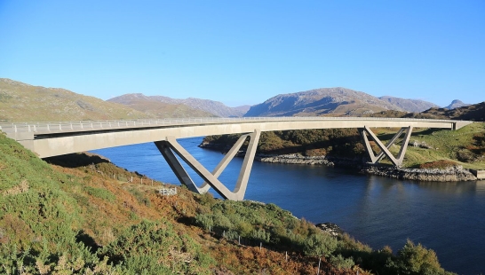
Figure 1 – Kylesku Bridge, Scotland [A]
3.2 What is a concrete aggregate?
Along with cement and water, concrete aggregate is a granular material which is compulsory in a concrete mixture. As this forms the bulk of the mix and provides a load bearing material that gives a mix designs compressive strength. Traditional concrete aggregates include sand, gravel, and crushed stone.
An ideal concrete aggregate should be hard, durable and clean. The parent rock type from which the aggregate is formed contributes to the consistency in aggregate size. Therefore, the quality of aggregate will determine the quality of concrete as it accounts for 60-70% of the concrete mix.
Aggregates are separated into two categories – Fine and coarse. Consistency in the aggregate size is important as it can determine the quality/strength of the concrete. A grading process occurs to ensure equal distribution or specific range which is required. 20mm is the max allowable aggregate size for a concrete mix design. This is broken down further into ratios of 10mm and fine aggregate in accordance with the Eurocodes. (3)
Grading can also determine the water: cement ratio. This determines the max aggregate size in the sample. The range allowed for aggregate size is usually broad and does not affect the overall strength of the concrete. However, for a more uniformed finish where the concrete aggregate will be exposed then stricter limits on aggregate size are enforced. This is outlined in Eurocodes I.S. EN 206-1 where a grading for size is given of different categories of gravel suitable for use.
According to Table 3 of the Eurocodes, IS EN 206-1, the workability of concrete is vitally important and can be associated with the aggregate shape (3). Excess water in flat aggregates should be avoided. On the other hand, coarse and angular concrete requires an increase in water to improve workability. This, in turn, reduces the overall strength of the concrete sample. It is advised that flat slender aggregate is kept to under 15% of the total unit volume. (2)
3.3 Recycled Aggregates
The use of recycled aggregates is a new method in which the dependency of virgin aggregates can be reduced. Waste aggregates which are no longer of beneficial use can be converted back into the production cycle as recycled aggregates. Following a recent research carried out by C. Meyers of Columbia University USA, these can include, crushed glass, crushed rubber, and crushed rubble. It is important that recycled aggregate correspond to the specific criteria of aggregate and adheres to the concrete design requirements (4).
3.4 Importance of aggregates in concrete
Portland Cement Association outlines the importance of recycled aggregates as: Cheap, effective and widely available (2).
“An aggregate is a granular product obtained by processing natural materials. It may be a sand or gravel produced by natural disintegration of rock, or it may be manufactured by passing rock through a series of crushers”. (3)
Aggregates make up a large proportion of the solid material in any concrete mix and a large amount of consideration must be given when designing any concrete mix. When a lot of aggregates are used, the possibility of inconsistency must be looked at as aggregate can vary depending on where it is taken from and this can be the case even in a quarry where aggregates are taken from different areas of the quarry. It is vital that an Engineer looks at this issue from the start to ensure that the aggregates used are consistent. This ensures that they will remain consistent throughout the project. Guidance of the use of I.S. EN 12620:2002. Aggregates for concrete is shown in Table 1. Reference should also be made to B.S 882, 1199, and 1200 which addresses different size particles both fine and course as well as a breakdown of mix ratio of particle sizes. (5)
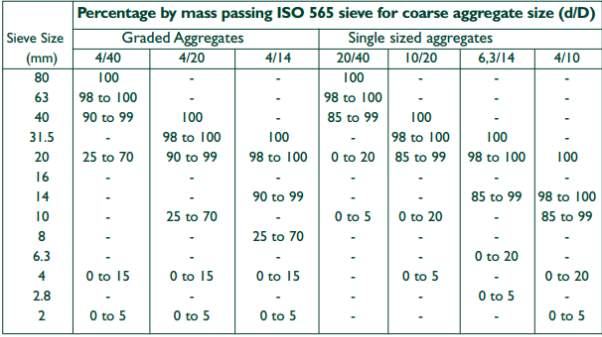
Table 1- Grading of aggregates (3)
Aggregate can also be classified by the different shaped particles which make up the core structure of aggregates depending on where and how the gravel was made/formed. The British Cement Association list the three main aggregate classifications are:
Round Aggregates: Generally made naturally from well-worn materials such as river or beach gravels which has been eroded by abrasion to form round smooth round pebbles (2).
Irregular aggregates: Are generally sourced from rivers and are irregular as there is a number of different sized gravel all mixed together to form a bed of river pebbles, these are generally removed and used for aggregate. The issue with this source is it is not consistent and would need to be graded to ensure consistency (2).
Angular aggregates: These are generally man-made substances which are made by crushing rock into smaller particles to form gravel used to make aggregates. The difference between this method and the natural gravels is that the particles are not smooth due to lack of erosion and abrasion and are like a fragment of the former rock substance from which they are crushed (2).
The shape and porosity of the material, as well as the grading can often affect the surface finish of the concrete. This is because the shape and quantity of a particular size of aggregate will have an effect on the surface finish. This will result in voids in the surface and the mix holding air.
The moisture of aggregate can greatly affect the bonding and consistency of the mix. When aggregate such as sand has moisture it can have an effect on the consistency as its density changes due to the moisture contained within the sand. For example 1m3 of sand with water added increases the bulk volume to 1.25m3 after this point adding water will decrease the volume until it reaches its saturation point at which the volume will have decreased to 1m3 again at its final saturation point.
This point is very important to take into consideration when storing aggregates on-site as the water quantity can change of aggregates are left exposed to the elements. If sand or other aggregates are sourced from different suppliers or supplies from different areas of the quarry the water content will be different and will not have the same consistency when mixed. For this reason, allowances should be made in the ratio of water added to allow for the moisture that is already contained within the aggregate (2).
3.5 The use of recycled material in concrete
A standard concrete mix is generally made up of water, sand, cement, and gravel. The gravel content is generally made up of crushed stone which has a consistency suitable for concrete. (See section 6.2 – Mix Design Ratio, Table 9)
The suitability of using recycled materials for replacement of aggregate is examined through strength, texture and the compression that the material will be able to withstand without failure. These attributes highlight whether recycled material is a suitable replacement for the stone aggregate and also if it is suitable to use in mixes for construction proposes. According to I.S. EN 206-1, Table 1, the proposed target of C20 concrete needs to have a compression strength of 20 N/mm². (3)
In theory glass, rubber and recycled concrete aggregate are three suitable replacements. The quality and durability of these products are tested in the laboratory by making cubes and then crushing them.
Conservation is a major part of using recycled materials in concrete as this can have a positive impact on the environment. RIAI (Royal Institute of the Architects of Ireland) defines conservation as “the process through which the material, historical, and design integrity of humanity’s built heritage are prolonged through carefully planned interventions (6).
This is already the case in North America and Japan where up to two-thirds of building waste is stone and masonry which could possibly be re-used to make new aggregate for use in concrete. Despite the processing cost of the recycling process, it is becoming financially viable to produce. This becomes useful when it comes to a country where rubble disposal is very expensive and land is scarce in which it can be disposed of. The use of recycled aggregates can also save new natural aggregates from becoming depleted over time.
This is something that has been a major worry in recent year in countries such as Denmark and Sweden (7). It is hoped that 40% to 50% of rubble could be recycled and used in making new aggregates. The main issue with recycled aggregates is that they have a higher porosity and require a larger volume of water when used (8) . This can be reduced by adding natural aggregate to the mix.(8)
3.6 Recycled Concrete
Recycled concrete is generally made up of old building rubble which is broken down and crushed into a finer sieved material which has the correct ratio of fines to larger aggregate. The difficulty with using this type of material is that the general principles of cement making are changed slightly due to the fact there are a greater number of fines in the mix and also recycled material having a lower density due to the fact that that there is already cement in the mix bonding fine aggregate together from previous uses. There is also a larger water abstraction rate which is caused by the cement contained in the recycled aggregate mix. One big issue that has raised from the use of recycled materials is that traces of contaminated material such as plaster, gypsum and wood which can greatly affect the durability and strength of the concrete and cause impurities. These can re-act with the chemical reaction in the concrete mix which cause weakness or inconsistencies in the mix and resulting in failure (8).
Recycled concrete usage can affect the strength by between 5-24% (9). When a mix ratio was formed it was found that the strength could be reduced by up to ranges of 15 to 40%. Most of this strength loss is due to the particles smaller than 2mm which cause a loss of strength and also can affect the permeability and hence the durability of the concrete. The mix can also be affected by the shrinkage of the concrete, the use of recycled concrete has its advantages as it is cost effective if the material i.e. rubble is sourced from a nearby demolition and it doesn’t need to be transported far for processing or reuse. Also, the use of recycled concrete aggregates can be very effective for use as a weak or filling concrete and would be of benefit in areas with very little natural virgin aggregate available to the consumer without large transport costs (9)
3.7 Characteristics of Recycled Aggregate in the Eurocodes
3.7.1 Compressive strength
For this category of the Eurocodes, it states the correct compressive strengths for a certain grade of concrete and what the limits a specific grade of concrete should be. (Table 2 Compressive strength classes) shows the required grade of concrete vs. the specific compressive strength class of a cube. Using the table published it can be seen that the grade of concrete achieved will fall between the limits of the Eurocodes for that particular grade of concrete. The Eurocodes specify what strength is to be achieved and for what grade of concrete it can be classified.
Stated in I.S EN 206-1:2002 are specifications required for a particular mix to put into a strength classes, (Illustrated in Table 2). ‘C’ denotes Class strength characteristics for the compressive strength of a cube (3).
| Required Grade N/mm2 | Specific Compressive Strength Class |
| 10 | C8/10 |
| 15 | C12/15 |
| 20 | C16/20 |
| 25 | 20/25 |
Table 2- Compressive Strength classes
To ensure compliance with the standards the compressive strength of cubes will have to be checked at intervals of 7, 14 and 28 days. The cubes are then assessed to see if the required strength classes have been met. Therefore, determining whether it is possible for recycled aggregate to be used in the construction of concrete.
3.7.2 High early strength
High early strength is something that must be addressed and is looked at in the Eurocodes to establish the curing rate of the concrete and the structural integrity of the concrete at that point in time. This will determine the grading curve for the strength class of the concrete, will be able to establish the strength of the concrete at a particular time frame and find the rate of curing and the rate at which strength is achieved during the use of recycled aggregates. These have to fall between the guide limits which are stated in the Eurocodes.
Similar enquiries and investigations have to be used to take the low early strength into consideration as this will have a knock-on effect on what can be considered correct construction practices to work on and have load bearing bodies bearing down on the concrete as if it has not cured properly. A low early strength concrete can be considered too early to work on and will cause cracking and failure in the concrete element of the structure.
3.7.3 Working life
The working life of a structure needs to be taken into consideration due to the fact that some concrete classes will only have a set lifespan of a given number of years after which point there can be little or no guarantee that the structure will remain its structural integrity. The Eurocodes specify guidelines which state as to what a particular time frame a building should stand for and how long it should be in use. This will determine the strength class and grade of concrete needed. The Eurocodes states that in IS.EN 206-1:2002 (Ref Table 3 Working Life Of a structure) the working life of a structure based on the strength and design characteristics of the concrete designed.
For the use of recycled aggregate in concrete is something that must be taken into consideration as the components can vary as it is recycled and in some examples may contain substances that may not have the same capability in relation the time due to weathering and corrosion. This must be taken into consideration in the design of a concrete mix and work out the life span and strength class of the concrete. If using recycled materials then the characteristic of the mix will have to be similar to what is specified in the Eurocodes for a standard mix.
| Temporary Structures | 10 years |
| Replaceable Structural parts | 10- 25 years |
| Agricultural & similar Structures | 15-30 years |
| Building structures and other common structures | 50 years |
| Monumental building structures,
Bridges and other civil engineering structures. |
100 years |
Table 3- Working life of a structure
3.7.4 Exposure class
The Eurocodes highlight the need for consideration to be given to the exposure classes that concrete mixes are exposed to depending on the environment in which it is placed. This is referenced in IS EN 206-1:2002 (Ref. Table 4 Exposure Class). The exposures class show the conditions which may have an effect on the structure of the concrete over time due to erosion and corrosion. This can be used to determine the exposure class that the structure will be exposed too. The use of recycled concrete should be tested to determine the strength against exposure for its intended use and whether it will be sufficient and provide the same or more resistance as the desired standard mix.
| Designation | Description |
| XO | No risk of corrosion or attack |
| XC | Corrosion induced by carbonation |
| XD | Corrosion induced by chlorides other than sea water |
| XS | Corrosion induced by chlorides from seawater |
| XF | Freeze/thaw attack with or without de-icing agents |
| XA | Chemical |
| * | Abrasion |
Table 4 – Exposure Class
3.7.5 Minimising cracking
The Eurocodes specifies the acceptable extent of cracking for a particular piece of concrete, anything more will not be suitable for its intended design. The Eurocodes give a precise description of what is acceptable and what cannot be used. In this instance, the concrete mix with recycled aggregate will have to withstand the same amount of cracking and if more than the desired limits are reached then the concrete will fail and will not be suitable for the desired use.
3.7.6 Aesthetic Considerations
Aesthetic consideration is listed in the Eurocodes as certain categories of concrete need to be used for certain finishes as this is shown in the Eurocodes. There must be a required finish depending on the intended use of the structure, for instance, the use of a footpath (Illustrated in Fig 2 Standard Footpath finishes),will have a different surface to that of a polished floor, shown in (Illustrated in Fig 3 Polished Concrete Floors), in a building and this will require a different quality of finish. IS.EN 206-1:2002 specify the finish required of different buildings and give the limits of each type of finish. (10)
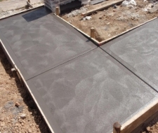
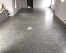
Figure 2 – Standard Footpath Finish [A] Figure 3– Polished Concrete Floor[A]
4.0 Sustainability
4.1 What is sustainability?
The Brundtland Report which was published by the United Nations of the World Commission on Environment and Development was the first to break ‘sustainability’ into three areas; social, economic and environmental (11). The use of recycled construction materials is key to achieving these three goals, as the construction industry progresses the need for new ideas amplifies. Therefore, now is a better time than ever to break the mould on new construction methods.
Currently, the standard approach for processing materials is linear; Extract, process, manufacture, use, demolish and discard.
However, forward thinking is curbing the material process into a ‘closed-loop’; Extract, process, manufacture, use, demolish, recycle (as many times as possible), eventually discard.
For many years the reuse of valuable materials such as tiles, slate, and brick have been kept and reused. However, the construction industry is becoming more self-aware of the importance of materials and the impact waste has. A recent journal published, ‘Construction and Building Materials’, describes one of the main barriers preventing ‘sustainable build projects’ from being sustainable is the use and treatment of waste generated on-site (12).There are several forms of waste which slowly build up over the construction process and builders waste is one of the main culprits during a construction process. However, there are many ways in which waste can be minimised and reused. (13)
4.2 Methods of obtaining ‘sustainability’
Sourcing and utilising ‘sustainable’ materials for a project is important for a design. Sustainable materials allow ‘waste’ materials to be reintroduced and reused in the construction process and thus reducing the dependency of virgin material. (In this context waste materials is referred to as, material that has exceeded its expected lifespan or is no longer of use). The Institution of Civil Engineers (I.C.E.) state that sustainable materials must:
- Not deplete non-renewable resources,
- Harm/affect the environment through its usage.
In reality, it is extremely difficult to achieve both of the above requirements, but it does highlight the direction needed for the future. There are new tools and techniques which can be adopted. (13)
These tools and techniques include;
- Using materials which have a low carbon impact and can be accounted for using programmes such as EcoPoint. This would give a single numerical answer for each material and could interpret the quantity required for each project. Carbon impact was described in a report by The Institution of Structural Engineers as the amount of carbon dioxide released in the production and use of a material (14).
- Methods of construction which account for carbon dioxide emissions as a single measure (kg) and can be processed using a ‘carbon accounting’ programme. These programmes calculate the carbon footprint and embodied energy of a project which depends on transport distance, materials used, recycled aggregate content etc… This report used a carbon calculator designed by The Environment Agency (See Section 8 – Pairc Uí Chaoimh Concrete Take-off) (15).
- The consideration of the transportation of materials. Reducing transportation in turn reduces the use of fossil fuels, emissions and road congestion (14).
- Choosing an ‘environmental material’ as a substitute for a ‘normal material. The Journal of Green Building associates environmentally friendly material as renewable materials e.g. timber, or a material which can be reused repeatable e.g. concrete aggregate (16).
4.3 The use of materials with recycled content
It is estimated that up to 20% of construction work can be completed using recycled content. As well as lowering costs this also helps gain BREEAM credits for a project (See Section 3.4 – BREEAM). There are many aspects of a construction process which could benefit from the use of recycled material. Recycled content (RC) can be widely obtained from recycled aggregate in concrete. It is suggested that nearly 40% of concrete can be recycled after demolition (depending on its source and prior use). Another source of obtaining RC is through the use of by-products created in the processing of cement and steel. Nearly 15% of this waste, known as Pulverised Fuel Ash (PFA) and Ground Granulated Blast-furnace Slag (GGBS) can be accounted for as recycled content.
Other areas where large quantities of recycled material can be found is through the use of precast concrete beams and ’recycling roads’. Recycling of roads is when material generated from the removal of roads is recycled in other road constructions. It is estimated in France that only 10% of material generated is recycled, according to a report carried out by the French Hydraulic Binders Industry Technical Association (17).
The concept of using recycled material within a project is starting to gather momentum (18). There are currently several concrete products on the market which contain recycled aggregate. These include concrete pipes, drains, curbs, decking and beams all which can contain up to 60% recycled aggregate. As well as concrete, steel, timber, plastic and glass are being recycled from projects and reintroduced into the manufacturing process.
4.4 BREEAM
4.4.1 What is BREEAM?
BREEAM (Building Research Establishment Environmental Assessment Method.) was launched in 1990 and is an environmental assessment for developments. It sets best practices and benchmarks for developments and projects. BREEAM has become the leading system and is widely used with over 115,000 buildings certified and 700,000 buildings registered. BREEAM aims to mitigate the impacts of buildings on the environment, provide a credible, environmental label for buildings, stimulate a demand for sustainable buildings and also give recognition for a buildings environmental efforts. BREEAM is operated and overseen by an independent Sustainability Board. This ensures project teams that the development is maximising its environmental gain and adhering to the required standards. This quality assurance is useful as a marketing tool for potential purchases.
4.4.2 Quality Assurance and Governance
To enforce monitoring and quality assurance for developments, The Sustainability Board oversees the publications, standards, and certification of BRE Global in the area of environment and sustainability. The Sustainability Board consists of a large variety of personnel from across the construction industry. These include, designers, developers, end users, financiers, insurers and regulators (19). A key objective of the BRE Global Governing body is to ensure the objectives are current and meet the needs of the industries stakeholders. The BRE Global Governing body meet three times a year to update its publications and standards. Some of the Sustainability Board responsibilities include:
- Ensuring a balanced participation with no single interest predominating.
- Advising BRE Global on relevant legislation and technical matters.
- Reviewing and advising on complaints.
4.4.3 Categories focused on by BREEAM
There are ten key categories which BREEAM focuses on, these are:
- Management (10 Credits)
- Health and Wellbeing (14 Credits)
- Energy (21 Credits)
- Transport (10 Credits)
- Water (6 Credits)
- Materials (12 Credits)
- Waste (7 Credits)
- Land Use and Ecology (10 Credits)
- Pollution (12 Credits)
- Innovation (10 Credits)
*The maximum number of credits available for each category are shown in italics.
A total number of 112 credits can be awarded to a project. This would result in a score of 100% and the awarding of an outstanding certificate.
The category of most interest for the use of recycled materials is ‘waste’. Within this category, BREEAM specialises on the use of recycled aggregate, a sites recycling facilities and its use/disposal of construction waste.
4.4.4 BREEAM Scoring System
Each individual project is assessed and credits are awarded based on the 10 categories throughout the project. An overall mark is awarded and a result of either Unclassified ((Fig 4 BREEAM weighting systems per category).
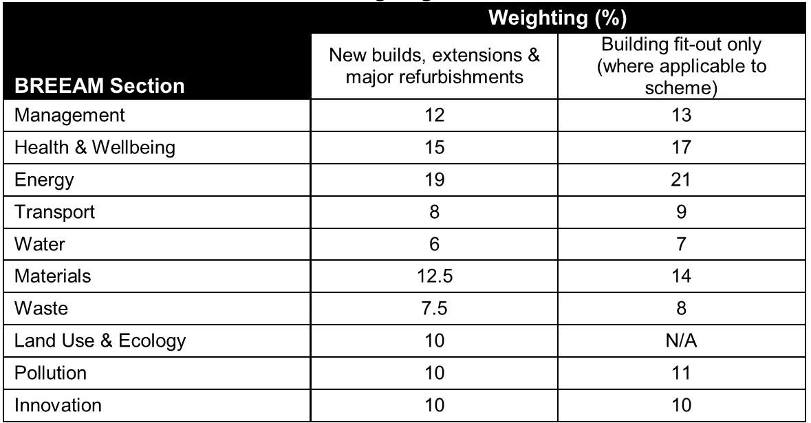
Figure 4- BREEAM weighting system per category [B].
The minimum credits required for a project to be eligible for an overall result are outlined in (Ref. Table 5 Category Weighting Systems). This lists the standards which must be achieved in order to be recognised for an awarding of a certificate. Several categories can be associated with recycled aggregates. Although ‘storage of recyclable waste’ is an obvious choice, reduction of CO2 emissions and low or zero carbon technologies could also be associated. Therefore, to obtain an ‘outstanding’ award emphasis should be placed on different aspects of the development and overlapping of categories should be targeted.

Table 5- Category Weighting System
4.4.5 Criteria for BREEAM waste category
BREEAM defines a recycled aggregate as a material which is derived from reprocessing materials previously used in construction. Secondary aggregates are defined as by-products of industrial processes that can be processed to produce a secondary aggregate.
The main objectives of BREEAM in relation to recycled aggregates is to encourage the use of recycled and secondary aggregates in construction and therefore reduce the need for virgin materials. Different stages of construction and different forms of constructions are listed and assessed in BREEAM. New builds, refurbishments, shell outs and fit outs can be awarded credits. The criteria for compliance is broken down as follows:
The amount of aggregate or secondary aggregate used during construction must be at least 25% of the specified (by weight or volume) of the high-grade aggregate. This is outlined in BREEAM Scheme Document SD 5052 and can either be:
- “Obtained on-site OR
- Obtained for waste processing plants within a 30km radius of the site. The aggregate obtained may be from a construction, demolition or excavation project OR
- Secondary aggregates obtained from a non-construction post-consumer or post-industrial by-product source.” (19)
According to RILEM, a technical association developing the knowledge of properties of materials and performance of structures, concrete which contains recycled aggregate can be broken into three separate categories which depend on their intended use and properties. An understanding of the recycled aggregates properties and capabilities is important to ensure they are adequate for task intended.
“Class A: recycled aggregates for use in a wide range of concrete including marine environments,
Class B: covering most combinations of natural and recycled aggregate and suitable for most ‘moderate’ exposure conditions,
Class C: those aggregates suitable for only the ‘mildest’ exposure conditions.”(20)
(Ref. Fig. 5 BREEAM Recognised by Products) shows viable secondary aggregates for the use of construction which are recognised by BREEAM. The maximum number of credits available for the use of recycled aggregate is 1 credit out of a total of 112 credits for an entire development.
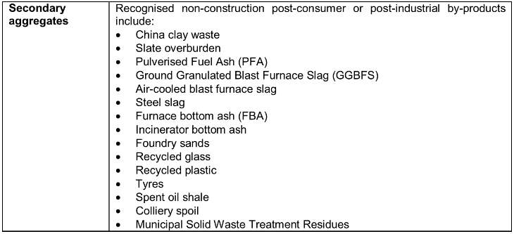
Figure 5- BREEAM recognised by-products [B]
4.4.6 BREEAM across the globe
With over 70 countries across the globe using BREEAM, it is expected that each country will have different requirements to tailor for their specific environment. Therefore, the governing body for each country is slightly different in its awarding of credits for a building. In Europe, certain countries have assembled National Scheme Operators (NSOs). These NSOs are allowed to redesign the requirements for their country as long as they correspond with the existing BREAAM standards, Core Technical Standard and Core Process Standard. These standards expand the framework set out by the Code for sustainable Built Environment (19). The NSOs for some European countries include:
- Netherlands – the Dutch Green Building Council operates BREEAM NL
- Spain – the Institute Tecnológico de Galicia operates BREEAM ES
- Norway – the Norwegian Green Building Council operates BREEAM NOR
- Sweden – the Swedish Green Building Council operates BREEAM SE
- Germany – the German Institute for Sustainable Real Estate (DIFNI) is operating BREEAM DE.
4.5 Embodied energy
Embodied energy is the energy consumed by all of the processes associated with the production of a building (21). This embodied energy is measured from the start to finish of a building’s lifespan. Initially, the energy consumed during the extracting, manufacturing, processing, transportation and erection of the material has to be accounted for. Maintenance of the building materials throughout its lifespan are recorded. Operational energy, such as heating, cooling etc… of the building attribute to the energy of the building. Finally, the demolition and disposal/ recycling of material at the end of the lifespan of the building equates to its total embodied energy. (21)
The total embodied energy of a building is calculated as so:
Initial embodied energy + Recurring embodied energy + Demolition energy.
Therefore, as energy consumptions within buildings improve the focus on embodied energy will become more significant. This will increase the importance of BREEAM guidelines for companies who aspire to achieving a high standard.
4.6 Sustainability of Concrete
Concrete in comparison to other materials has a high embodied energy. This is due to the large process it undergoes before it can be used (Extraction, manufacture, and transportation).The large role moisture plays within a concrete mix design may be affecting the materials viable use as a recycled material in the future. However, concrete is low maintenance, high durability and can provide thermal mass which would deem it as a sustainable material within a building.
4.7 Case Study – (Cement Roadstone Holdings – CRH)
CRH is determined to reducing its carbon footprint and CO2 emissions each year. CRH is committed to delivering a built environment which is sustainable and friendly to the local community (22). Through its annual company reports, it is evident that CRH is achieving its goals and continues to strive for the future
“Having achieved our 2015 carbon and air emissions targets ahead of schedule, we are on-track to achieve our 2020 commitments.”
CRH uses large quantities of materials throughout their production process. In 2015 33.5m tonnes of cement, 270.3m tonnes of aggregate and 54.5m tonnes of asphalt were used. However, in order to help maintain on track for its 2020 goal they have focused on the development of climate-friendly materials, such as lower carbon cement, warm-mix asphalt, and recycled aggregates. Some of CRH’s 2020 goals include the reduction of specific net and dust cement C02 and NOx emissions by 25% and 80% respectively and the reduction in average clinker particulate emissions by 80%. (All goals are benchmarked off 2006 levels).
CRH tries to ‘close the loop’. Materials which would normally have to be disposed of are now recycled and reintroduced into the production process. Not only is this procedure lowering the company’s carbon footprint but also helps manage their supply of a finite resource. CRH currently runs a ‘C4C’ (Cycle for Concrete) programme in the Netherlands. This programme encourages customers to remove old concrete paving for recycling into a high-quality raw material and reused in new paving. This new product is then supplied to the same customer. In 2015 alone 22.8m tonnes of recycled materials were used. This equates to 8% of the company’s overall virgin material input. Approximately 9% of the company’s CO2 emissions are generated during the production of asphalt, aggregate and ready mixed concrete and therefore it is crucial that there is a continued inclusion of recycled materials throughout the production. (Ref. Figure 6 C&D Used by CRH) shows the million tonnes of C&D materials produces by CRH in recent years. (22)
4.8 Aggregate Tax
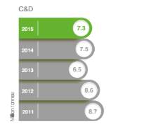
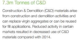
Figure 6– C&D used by CRH[C]
There are many reasons for finding uses for recycled material, for instance, the waste from construction takes up huge volumes of space in landfills and causes problems with pollution. The fact that materials which are disposed of can be recycled as stone and aggregates are a finite resource and will become depleted. New incentives are put in place to ensure the safeguarding of finite resources such as stone just like that of peat and coal. One that solution was put in place by countries such as Denmark and Sweden to impose taxes on the use of virgin aggregates
“A recent study has investigated how taxes on virgin raw materials used in construction, such as gravel and sand, have reduced the use of these resources, based on experiences in Denmark, Sweden, and the UK. However, greater incentives to recycle these materials are still needed, says the study.”
It is hoped that by using tax on newly quarried aggregate which will case an increase in the cost of the raw materials that this may help in reducing the amount of virgin aggregates used as an incentive that the use of natural virgin aggregates will decline in use and will cause new solutions and products to be made from recycled materials. This would be less environmentally damaging and would help preserve resources and reduce emission caused by the production of the aggregate. In cases where the emissions are difficult to monitor taxes are the only suitable way of imposing sanctions on the use of natural aggregate. This is the case in several European countries such as Sweden, Denmark, and the U.K.
In Sweden aggregate tax was first introduced in 1996, the idea behind this was to promote the use of crushed rock and recycled materials. The reason that the Swedish government imposed the tax was to help in the ever-depleting natural aggregate found in the country and to reduce the effect of quarrying and the damage it does to the landscape. The tax has been successful in reducing the dependency on natural aggregates as it was imposed on the entire country even in areas where the natural resources were being quarried.
In Denmark taxes were first introduced in 1990 following the introduction of a waste tax. The incentive behind this was to promote the use of recycled materials and help prevent the depletion of natural resources by replacing it with the use of recycled concrete aggregate products. This has caused a significant decline in the use of virgin aggregate in the country. The figures show the increase in the use of recycled aggregates going from 12% in 1985 to 94% in 2004. (23)
The U.K have also imposed a tax on aggregates which was introduced in 2002 and was aimed at the reduction of environmental damage caused by the quarrying of rock. Although the use of recycled material has increased due to the tax implementations and an extra expense of buying virgin aggregate it doesn’t address the issue of pollution and damage to the environment directly. This is evident as quarrying and the use of virgin aggregate is still quite prominent.
It can be seen that taxes reduce the amount of virgin aggregates being used and promotes the use of recycled materials as aggregates and puts an initiative in place to stimulate the development of new more sustainable replacement aggregates. Other aspects that can be looked at would be removing subsidies and grants for infrastructure and developments if a certain amount of the aggregates used are not from a recycled source or offering grants for those who use them. Although tax is an initiative for change it doesn’t prevent the pollution and depletion of the raw materials used in aggregate which leaves scars on the landscape and causes pollution. (23)
5.0 Concrete Mixing Handbook
5.1 The basics of making a standard concrete mix
The basic principle of ‘concrete making’ is to mix sand, gravel, and cement with water to cause a chemical reaction in the mixture to occur. The resultant is a hard dense material known as concrete. A strong durable mix which can be used for a number of building purposes in the construction industry. The basics of a concrete design are based on the material strength of the mix and the ratio and use of material in the mix. Concrete can be made from many different mixtures depending on the use, strength dependency as well as the density/viscosity of the material which will depend on the way in which the concrete is to be poured. Concrete can be poured in a number of ways. Standard ready mix concrete usually has a dense and consistent solid appearance and texture and so generally is workable with a rake and shovel. Therefore it is often poured in sections to give time for the concrete crew to work it into the formwork and screed and float it to the desired finish. (24)
The basic concrete mix contains cement, sand, and gravel in a ratio of 1:2:3 (24) and forms a workable concrete mix which is suitable for most domestic and small scale commercial projects. The standard concrete mix is workable to a level which is suitable for small scale pads and used in projects which have a small scale area which can be worked into the formwork in a small period before the concrete begins to cure (Illustrated in Figure 7 Standard pouring of concrete).
For large scale projects where concrete is used for instance, commercial warehouse or retail unit the concrete is specially adapted to give it greater workability over large areas so that it can be worked with greater ease into large surface of formwork and prevent it from curing too quickly. In cases like this concrete will be mixed using a standard ratio of each material but a superplasticizer is added which causes a chemical reaction. The material becomes almost liquid like and so becomes very workable and also is generally pumped in this state through a concrete pump on-site from the mixer to the formwork (Illustrated in Figure 8 Pouring of superplasticizer). The superplasticizer has no effect on the curing or quality /strength of the mix and will cure correctly and give the correct strength after 28 days. (Ref. Eurocodes IS EN 206-1). The idea of making concrete more workable using water is incorrect as this corrupts the correct ratio of the mixture and causes the desired strength of the concrete mix to be jeopardised, causing major defects and issues. (24)
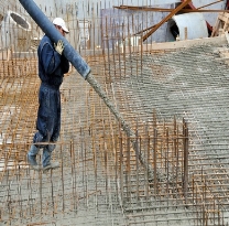
Figure 7 – Standard pouring of Concrete [A]
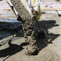
Figure 8– Pouring of superplasticizer[A]
Certain issues that can be seen from incorrect usage of water are issues such as bleeding which causes the concrete to release water to the surface which is pushed out as the concrete begins to dry and cure. This causes the surface to have pools of water which can have an effect on the surface of the material as it can cause the cement to be diluted and separated from the sand and gravel which can have a knock-on effect on the surface of the concrete and cause a disintegrating surface. The surface is not very durable and so can often lead to small fissures and depression occurring in the surface. These can be enlarged over time due to sweeping or washing in the case of a floor surface in a garage or commercial unit (Illustrated in Fig 9 Bleeding of Concrete). (24)
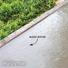
Figure 9 – Bleeding of Concrete [A]
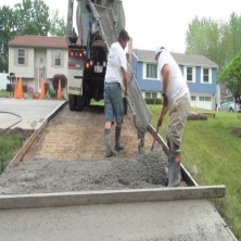
Figure 10- Screeding of Concrete[A]
As well as bleeding the quality of concrete can be affected by the trapped air and in all cases, the concrete mix should be poured in section into well-constructed formwork which is designed to hold and maintain the concrete as it cures. Concrete must be tamped to remove trapped air and force the concrete into any voids that may otherwise be left unfilled which may cause major issues when it comes to compressive strength. As well as tamping the concrete must be screeded which involves the use of a 38mm x 89mm plank with good quality edges to give a good quality finish. (Illustrated in Figure 10). The plank should be used on edge to prevent distortion of the plank. The plank itself should be shuffled along the edge of the formwork on either side of the area to be poured. The reason for this is to level off the concrete surface and provide a semi-finished level surface. (24)
The surface should be vibrated using a vibrator to remove air bubbles from the mix which can often become lodged in the mix and can cause air voids in the mixture, these lead to weaknesses in the finished concrete. The edges of the formwork should also be vibrated or tapped to remove any trapped air held between the edge of the concrete and timber formwork. This can lead to unsightly air bubbles and pours finish on the edge of the concrete which can be unsightly if edges are to be used for aesthetic purposes.
The final step in finishing a standard concrete pad or footpath or floor for domestic usage would be to float it. This can be done using a hand float or a power float depending on the level of finish required. (Illustrated in Fig.11 Floating Concrete). (24)
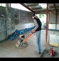
Figure 11 – Floating Concrete [A]
5.2 Slump test
For standard conventional works, the concrete should be tested using a slump test to measure the consistency and quality as well as the workability of the concrete. This should be done using slump test apparatus which include a slump cone and a 16mm diameter tamping rod. The slump cone is inverted on its base, placing feet over the foot grips to keep the cone in place, the cone is filled in three layers, each layer is tamped 25 times to remove any air that is trapped and to compress the concrete mix into place. (25)
When this has been done and the mould is full the top surface is rolled off using a tamping rod to finish the surface. (Illustrated in Figure 12 – Slump test procedure).
The mould is then removed carefully to prevent unnecessary damage. When the mould is removed it is inverted and a meter stick is placed across the top of the inverted cone level with the surface and the difference in height is found between cone and sample of concrete. This is known as the slump and is measured using as ruler from the bottom of the flat metre stick (Illustrated in Fig 13 – Slump test).
The slump test gives an indication of the consistency of the concrete and how workable it is when mixed and poured into formwork.
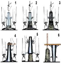
Figure 12 – Slump Test Procedure [A]
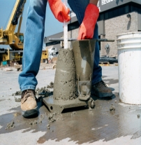
Figure 13 – Slump Test[A]
There are three main types of results that are looked for:
Zero slump: This indicates cohesion as well as good mix quality but also indicates that the workability of the concrete is quite low and would form a stiff difficult mix to work into from work. Used more in small surface areas e.g. strip foundation.
Shear Slump: In a shear slump the concrete shears off and slips down. This is because the mix may lack cohesion and also may need to be re-batched for a fresh batch to be re-tested.
Collapse Slump: This is where the concrete collapse completely and this may be caused by a mix that may be too wet or may have a superplasticiser to make it highly workable, in which case it will not perform at all in a slump test.
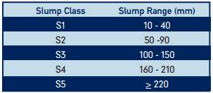
Figure 14 – slump test ranges Eurocodes IS EN 206-1[D]
5.3 Science of Concrete-Making
Concrete is a substance that has been made for over 100 years in one form or another, the science behind concrete making is something that is still being discovered to this day and concrete technology is an integral part of the design of all structures. Concrete has many uses and is used in many forms ranging from reinforced concrete to concrete fill and also used in floors, reinforced retaining walls as well as for a fill. Concrete can be moulded into any shape and can be used for a number of decorative and structural proposes.
Cement: cement is one of the most important components of the concrete mix and is widely used in all forms of concrete construction and making. Cement is a powder which is made from a chemical combination of calcium, silicon, aluminium, iron and other ingredients such as clay slag sand and iron ore which are heated in a kiln to very high temperatures to form a rock-like substance which in turn is ground down into a fine smooth grey powder. This type of cement substance is known as Portland cement and is the most common type of cement used in all concrete making today. (25)
The cement process is made using the dry method which involves crushing limestone and clay into smaller particles of about 6 inches and reduced further to approximately 3 inches in a secondary crushing process. The crushed rock is combined with other ingredients such as fly ash which is the ground down and fed into a kiln where it is heated. The materials are then heated to 2700 degrees Fahrenheit. After this occurs the material comes out of the kiln as small marbles of clinker which is grey in appearance, the clinker is then mixed with small elements of gypsum. The combined material is the ground down to a fine powder like substance which is so fine that 0.45 Kg of cement contains 150 billion grains. (25)
Sand: Sand is an essential part of the concrete making process and is used as an aggregate which is so fine that it fills all voids in concrete mix so that air is not retained. Sand provides a packing property that makes the concrete denser. The sand that is used in concrete is generally called sharp man-made sand which comes from crushed rock particles, used in the construction industry in concrete and mortar mixes. One very import thing to note is that sand used in concrete making must be clean and contain no organic or silt impurities as this will weaken the strength of the concrete. (26)
Aggregates: the use of aggregates in concrete is a very important part of the concrete batching process, the aggregate would generally be mixed in many cases the aggregates can be purchases in a pre-mixed sand and gravel mix so that the cement can be added with water and mixed to form concrete this pre-mixed aggregate/ sand mixture is a 50:50 ratio of sand to pea gravel aggregate. This mixture can be purchased from any building supplier or quarry. The aggregate must have the right constituents to perform to maximum strength and bearing capacity (Illustrated in Fig 15 – Proportion of a concrete mixture).
The purpose of the aggregate is to provide strength to the mixture and also to create bulking. The gravel in the mix provides strength as well as fill, while the sand fills all small voids and helps to avoid hollow pockets in the concrete.
Water: Water is a very important constituent of a concrete mixture as it causes a chemical reaction which causes the cement powder too change to a paste which bonds the aggregates together to form concrete. Water is put into the mix as a ratio of one part water or 1:6.25. (26)
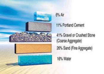
Figure 15 – Proportions of a concrete mixture[A]
6.0 Concrete Cube Making
6.1 Why concrete testing is carried out
Concrete testing is carried out onsite or in a laboratory. The main objective of carrying out these tests is to ensure that the concrete poured is to the design specification of IS EN 206-1. Concrete testing also determines the proportions of materials which are required to reach a mixture that complies with the standard. For onsite testing, a control needs to be established.
6.2 Samples used during testing
It is of upmost importance that a correct sample is taken to give an accurate representation of the entire consignment. As aggregate and concrete are diverse materials care needs to be taken to ensure the adequate amount and quality is used for testing.
6.2.1 Cement
Cement is rarely tested on-site. The vast majority of cement adheres to the BS EN 196-7:2007 standard.
6.2.2 Aggregates
The sample of aggregate used during testing must comply with the BS EN 932-1:1997 standards. Although it can be difficult to obtain an exact representation of a sample aggregate certain procedures may be used to make a more appropriate selection of aggregate.
A wide sample of aggregates need to be taken at different times and different locations to help give a good representation of the sample. If the sample in a pile then smaller samples should be taken from different parts of the heap at different times of the day. If the aggregate is being discharged off a conveyor belt then samples should be taken at regular intervals throughout the unloading process. If the sample taken is too large then it will need to be evenly distributed into smaller sections. This can usually be done using a riffle box. A riffle box is specifically designed to separate a sample. Pour the large sample into the top of the riffle box and it will approximately divide the aggregate evenly into two separate boxes. One of these boxes can be discarded. The remaining box can be tested further if required. The quality of the aggregate is important during riffling. Coarse material can be separated at any time but fine material will need to be surface dry to make sure the sample is riffled properly.
6.2.3 Testing of hardened concrete
It is well known that concrete is good in compression but poor in tension. Therefore to test for the ‘strength’ of concrete is usually obtained during compression tests. Although other non-destructive tests can be carried out, it is accepted that a compression test is best suited. (Ref. IS EN 206-1)
Test cubes are samples of a concrete mix usually tested under a compression testing machine to obtain the compression strength (27).
6.3 Test cubes
A maximum aggregate size of 20mm for a cube size of 100mm square is required. The construction of the cube is vitally important in obtaining accurate results. The cube is usually constructed using steel or cast iron with the base plate being removable. Attention to detail is critical with minute discrepancies in concrete characteristics. A thin release agent should coat the sides and base of the cube to prevent the concrete sticking. Concrete testing cubes should comply with the BS EN 12390-2 standard.
Concrete should be poured into the sample in two stages for a 100mm cube. First half fill the cube. By using a circular tamping rod with a minimum tamping size of 25mm2. It is recommended that at least 25 strokes are required for a 100mm cube. More strokes may be applied if further compaction is needed. The strokes should be evenly applied in an order and not focused over one particular spot. The remainder of the concrete is poured into the cube and the tamping process is repeated. The level of the concrete should be even and flush with the top of the cube. (28)
6.3.1 Curing of Test cubes
Once the concrete is poured it should be placed in a free location from vibration a damp room and wrapped in a plastic sheet to prevent moisture loss. Cubes should be demoulded at a period between 16-28hr after the time of pouring. Immediately the cubes need to be submerged in a tank of water with a temperature of around 20°C. It is crucial that each sample is clearly labelled and records are kept their. The reason for this is that if a cube fails a record of this particular cube is kept.
6.3.2 Testing of cubes
Testing of cubes must be carried out in a laboratory and are normally tested at 7, 14 or 28 days. In is accepted that concrete has reached 80% of its strength by 28 days. The appropriate standards must also be adhered to. The following procedure must be used:
- The cube should be tested immediately after they are removed from the water bath.
- Any impurities on the cube should be removed prior to testing. Dimensions and weight of the cubes should be recorded.
- The surface of the testing machine must be clean, level and properly aligned. Do not place the top or bottom of the cube at casting on the bearing surface.
- A load must be evenly applied at a pressure of 0.2-0.4 N/mm2s. This should be continued until no further load can be supported.
- The maximum load applied must be recorded for each cube. Any unusual failures should be noted and the failed test cube should be kept for at least one month.
- The testing machine must be in good working order and calibrated regularly. If the machine is improperly working low failure results will occur and give an inaccurate result. Types of failure should also be noted as obscure failure will indicate a fault with the testing machine. (29)
7.0 Concrete cube making Procedure
The following outlines the standard procedure which was carried out in Cork Institute of Technology laboratory for the sole purpose of this project. By carrying out the process, the ratios and results shown were calculated. These are not strict guidelines and the use of materials, ratios and hence, results can vary.
7.1 Introduction to Recycled Aggregate
To test if it is possible to use recycled aggregate in concrete and to test the procedure of making concrete using recycled aggregate. The aggregate used for research purposes which was sourced from Roadstone in Belgard Dublin which was transported down to CIT where it was refined. The use of this material required a large amount of refining so that it could be used in a concrete mix. This process will be shown in detail in the following chapters of this handbook which explain in detail the process of refining the recycled aggregate. The recycled aggregate used in this project consisted of crushed builder rubble which varied in size and had no consistence before sieving (Ref. Table 6 – Distribution of Aggregate). From looking at the rubble it can be seen that the profile of the material is not graded (Ref. Fig 17 – Large recycled aggregate).
7.2 Aggregate refining and sieving
For this research process after receiving the recycled aggregate is to examine the material and look at the quality and quantities of the aggregate. This process was completed by pouring the contents of each bag out onto a sorting tray and then filtering through the material by hand to remove any very large or unwanted materials from the aggregate (Ref. Figure 16 – Raw Recycled Aggregate). A number of different contaminants were be found in the recycled aggregate which needed to be removed, this includes items such as glass and clay particles, old clay piping, large limestone rock particle and large lumps of concrete which had to be removed as they are outside of the limits of a mix design and may have had an effect on the compressive strength and compatibility of the aggregate in the mix (Ref. Figure 17 Large Recycled Aggregate).
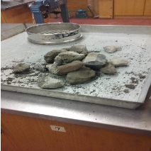
Figure 17 – Raw Recycled Aggregate [E]
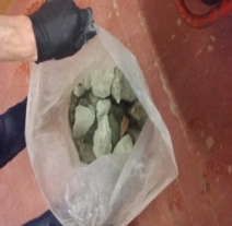
Figure 16 - Large Recycled Aggregate [E]
The next step is to dry the materials as the moisture is not consistent and cannot be of a usable nature and needs to be dried before sieving. This restricts finer materials from sticking to the sieves and prevents the fine material from passing through the trays. (Note: when taking on the task of sieving it is important that the materials should be sieved in small quantities as this will prevent the fine grade sieves from clogging and giving an inaccurate result of retention on the fine sieve.)
The aggregate is collected in portions and placed into a sieve of size 30mm. The material is sieved through until all particles smaller than 30mm pass through the sieve. (Illustrated in Fig 18). Material that is retained on the sieve greater than 30mm has to be removed and placed in a bag with the other large material. This can be stored until such a time as needed. The next step in the process is to add the
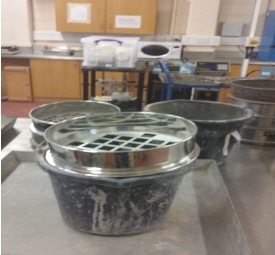
Figure 18 – Sieving of Aggregate[E]
| Aggregate Size | >20 mm | 20 mm | 10 mm | Fine |
| Weight (kg) | 32.78 | 12.547 | 13.707 | 52.316 |
Table 6 – Distribution of Aggregate
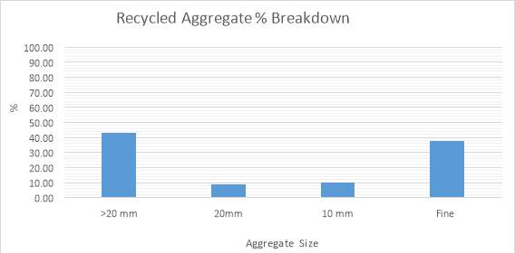
Table 7- % Breakdown of Aggregate
After the aggregate has been categorized, the weight of each has to be determined and the overall of the aggregate has to be broken down into percentages of the original weight of the bag of recycled aggregate and each aggregate categories volume can be found as a percentage of the overall percentage of the bag (Ref. Table 7 – Break Down of Aggregate). Place the recycled aggregate that has passed through the sieve shaker and categorised in pans for storage in a dry place so there is no change in the moisture.
7.3 Aggregate Crushing Process
To reduce waste and reduce the carbon footprint as well as using all of the waste product, all materials larger than 20mm in size were crushed using a sledge hammer until the pieces of aggregate where broken down into sizes that could be used in the mix (Ref. Figure 21 – Breaking of Aggregate).The categorisation of these aggregate sizes were found by sieving through a 20mm sieve. Material passed through a 10mm sieve and then through an 8mm sieve. The material which passed through each sieve but was retained on the smaller sieve e.g. greater than 8mm and less than 10 mm was retained as 8 to 10mm category (Ref. Figure 22 – Broken Aggregate Refined). This process was repeated for all manually crushed aggregate to provide optimum usage of all materials and to reduce waste. A particle distribution curve was concluded (Ref. Fig 20 – Particle Distribution Curve)
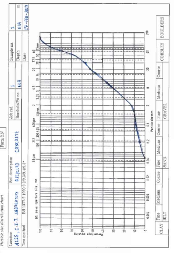
Figure 20 – Particle Distribution Curve [E]
Figure 19 – Particle Size Distribution Chart
7.4 Mixing process
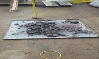
Figure 22- Breaking of Aggregate [E]
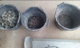
Figure 21 – Broken Aggregate Refined [E]
The mixing process can be repeated a number of times to form different mix characteristics using different ratios of aggregate both recycled and virgin. The main objective of this process is to obtain a number of cubes which can then be crushed and the compressive strength of the mix can be measured at 7, 14, 28 days.
The first mix to be made is a control mix which is used to gauge the compression characteristics of C20 concrete. By first making a control mix comparisons between the strength characteristics of a standard and recycled mix can be evaluated.
Table 8 and Table 9 show the percentage of recycled aggregate vs. standard (virgin aggregate). The mix design shows the ratio and amount of aggregates and cement as well as the volume of water required for a mix of 0.2m3 of C20 concrete.
Table 10 and Table 11 show the volume of materials used in the second batch of mixes which contains 50% O.P.C and 50% GGBS which gives the volume in Kilograms of materials needed for all constituents of the C20 concrete mix. This gives a mix design which can be used in the design of the cubes to be made.
The ratios of the first four mixes can be seen in the table below
| Mix No. | Description | O.P.C | % virgin aggregate | % Recycled aggregate |
| Mix Design 1 | Control mix | 100% | 100% | 0% |
| Mix Design 2 | 25% Recycled | 100% | 75% | 25% |
| Mix Design 3 | 50% Recycled | 100% | 50% | 50% |
| Mix Design 4 | 75% Recycled | 100% | 25% | 75% |
Table 8- Mix Designs Breakdown
Table 9 and Table 10 show the second mix of ordinary Portland cement and GGBS in a 50:50 ratio. This mix has variables in the percentage aggregate used.
| Mix No. | Description | O.P.C | GGBS | % virgin aggregate | % Recycled aggregate |
| Mix Design 5 | Standard Aggregate | 50% | 50% | 100% | 0% |
| Mix Design 6 | 25% Recycled | 50% | 50% | 75% | 25% |
| Mix Design 7 | 50% Recycled | 50% | 50% | 50% | 50% |
| Mix Design 8 | 75% Recycled | 50% | 50% | 25% | 75% |
Table 9- Mix Design Ratios
7.4.1 Mix design Ratios
| 0.2 m3 batch quantity | Standard mix (kg) | 75% Recycled (kg) | 50% Recycled (kg) | 25% Recycled (kg) |
| 20mm Aggregates | 15.66 | 11.75 | 7.83 | 3.915 |
| 10mm Aggregates | 7.85 | 5.89 | 3.93 | 1.962 |
| Fine Aggregates | 15.43 | 11.57 | 7.72 | 3.857 |
| O.P.C Cement | 5.40 | 5.40 | 5.40 | 5.40 |
| Free water | 3.06 | 2.29 | 3.06 | 1.53 |
Table 10- Mix Design Quantities
| 0.1 m3 batch quantity | Standard mix | 75% | 50% | 25% |
| 20mm Aggregates | 7.83 | 5.87 | 3.92 | 1.96 |
| 10mm Aggregates | 3.93 | 2.94 | 1.96 | 0.98 |
| Fine Aggregates | 7.72 | 5.79 | 3.86 | 1.93 |
| O.P.C Cement | 1.35 | 1.35 | 1.35 | 1.35 |
| GGBS | 1.35 | 1.35 | 1.35 | 1.35 |
| Free water | 1.52 | 1.69 | 1.74 | 1.52 |
Table 11- 50% OPC & 50% GGBS Mix Design Quantities
7.5 Mix method
The batching quantities which were used were that of 0.2 m3 as this is the smallest possible mix that can be made in a cement mixer as anything smaller would cause the mix to stick to the drum of the cement mixer and cause difficulty with the mixing process. The figures which were used were from Mr Brian O Rourke who provided a mix design for 0.4m3 of concrete mix which were factored down to the desired mix size of 0.2m3. The reason for this mix size was to reduce the amount of waste per batch after the cubes were filled and create less waste.
Firstly the materials have to be laid out in such a way as they could be weighed on the balance and then used in the mix, for this a simple procedure can be used.
- The aggregate is weighed on the balance and separated into the required amounts. (Note: care should be taken at this point as the weight of the bucket must be taken into account and recorded and then subtracted from the weight of the aggregate + bucket.)
- The aggregate, cement, and free water content are then placed in buckets and the mixing equipment is set up.
- All equipment should be set up and ready for mixing. The cement should be set up on a stand and a wheelbarrow should be at the ready for the mixed batch to be poured into.
- The next step is to prepare the test cube templates. The cubes should be oiled with shuttering oil to prevent the concrete from sticking to the cube and based plate.
7.6 The mixing process.
The mixing process itself should be done as follows:
- The mixer should be plugged in and turned on. (See Appendix D, Method Statement)
- The larger aggregate 20mm should be added first while the mixer is turning and then the medium 10mm aggregate. This should be left to mix for a minute or so in order for the two aggregates to thoroughly mix before adding the sand (fine aggregate), which should again be left for a minute to mix (Illustrated in figure 23 – Mixing of Concrete).
- The cement should be added with care as if caught in a wind it can cause skin and eye irritation and also respiratory problem, correct PPE should be worn at all times (dust mask, glasses, and gloves).
- The next step is to add water. Care should be taken as there could be a slight variation in the amount of free water needed. This is where the drying of aggregates is important and therefore water should be added with caution.
- The mix should then be left for a number of minutes to mix fully.
- The contents of the mixer should then be poured into the wheelbarrow with caution as it can cause the wheelbarrow to tip over (Illustrated in Figure 24 – Batching of Concrete).
- The mix should be completely removed from the mixer
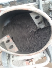
Figure 23 – Mixing of Concrete [E]
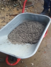
Figure 24 – Batching of Concrete[E]
7.7 Slump test
For each mixture, a slump test must be performed to check the workability of the mix. The desired slump for efficient workability should be 50mm as this would generally be used for standard mixes. If there is less of a slump then the mix can often be too dry and would prove difficult to work. The slump should come out of the slump cone without cracking or failing in shear as this indicates that the mixes workability is not satisfactory and needs to be discarded and a new batch needs to be mixed (Ref. IS EN 206-1).
If there is a large slump or if the mix pours out of the slump this indicates that the mix is too wet and will not be suited to a standard mix.
The correct procedure for a slump test is to test the mix as soon as the mix has been made, the method for this is as follows:
The slump test is repeated for each mix and the slump recorded (Illustrated in Table 12 – Slump test results).
| Mix type Description | Slump (mm) |
| O.P.C –STANDARD MIX (Control) | 50 mm |
| O.P.C- 25% recycled aggregate | 50 mm |
| O.P.C -50% recycled aggregate | 50 mm |
| O.P.C- 755 recycled aggregate | 50mm |
| 50% O.P.C /50% GGBS standard mix | 80 mm |
| 50% O.P.C /50% GGBS25% recycled aggregate | 40 mm |
| 50% O.P.C /50% GGBS50% recycled aggregate | 50 mm |
| 50% O.P.C /50% GGBS75% recycled aggregate | 40 mm |
Table 12- Slump Test Results
From the results above it can be concluded that the results of the slump are close to the required slump and will pass on workability.
7.8 Cube Filling
The next step is to make the concrete test cubes using the mix. This is done by getting the steel cube moulds which are open at the top and contain 0.001m3 of concrete and this will hold the concrete in place when curing.
The cubes must be coated with shuttering oil to prevent the cubes from sticking to the mould and makes it easier for the cubes to slip out and hence prevent the cubes from being damaged or chipped if they become bonded to the mould itself and required force to remove them (Illustrated in Fig 25 – Test Cube Moulds).
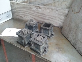
Figure 25 – Test Cube Moulds [E]
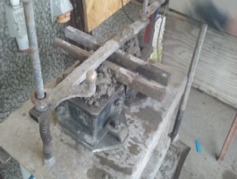
Figure 26 – Vibrating of Test Cubes [E]
The first step of cube making that is needed for this research is to place a quantity of concrete mix into the cubes and then place the cubes on a vibrating table to remove excess water from the mix. The vibration prevents honeycombing, stops air from becoming trapped in the cubes and prevents voids from appearing in the cubes which may jeopardize the strength of the strength of the concrete ( Illustrated in Fig 26 – Vibrating of test cubes).
The cubes are placed on the vibrating table two at a time and metal bars are placed on the top of the cubes to keep then it in place. The cubes are then vibrated for one minute and removed.
If the cubes began to sink down more mix can be added and this should be continued until the cubes can take no more. This indicates the cube is full and compacted into place. This process should be completed for six cubes.
The next step is to float off the top of the cube and remove the excess of the top layer. The cubes should be floated, trowelled off and finished smooth. (Illustrated in Fig 27 – Floating)
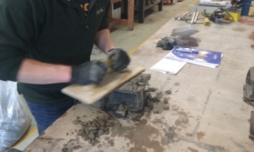
Figure 27 – Floating of Test Cubes [E]
The cubes are then left to rest for a day, taken out of the mould and placed in the curing tank and left for seven days. After 7 days two of the six cubes made from the same batch are crushed for compression testing.
7.9 Cube testing
The cube testing process involves the cubes which have been left to cure for 7, 14, 28 day. Two cubes from each batch are tested at the 7, 14 and 28 day mark. The reason for breaking two cubes from the same batch at the same time is to get an average. This process is repeated for all mixes using two more cubes at a time of 7, 14 and 28 days.
To crush the cubes put them into the compression tester and record the strength of each cube. A C20 strength concrete should be achieved by 28 days at which stage the cubes should have reached their desired strength. The overall desired result is to be able to compare the strength of the concrete cubes samples and see which sample has the greatest strength at 28 days. Depending on results it may be possible to determine if a replacement for standard concrete can be achieved using recycled aggregate and cement substitutes.
7.9.1 Crushing Process
After crushing the cubes they should be broken to remove any loose pieces and the centre should look like an apple core. This is the standard procedure and the aim is to get a similar result for both the standard and recycled cubes. This will help draw a conclusion on whether it is possible to use recycled aggregates as a substitute for virgin aggregate.
8.0 Results Interpolation
Points which should be taken into consideration before analysing results:
- The batch size for mixes 1 – 4 were 0.2m3, whilst the batch size for mixes 5 – 8 were 0.1m3. In theory this should not affect the strength of the cubes as all mixes were portioned accordingly.
- Mix designs 1 -4 were made from existing 20mm, 10mm and fine recycled aggregate. Mix designs 5 – 8 were made from recycled aggregates which had to be broken into the required sizes from larger stones.
- There was a substantial amount of clay brick within the recycled aggregate. This may have reduced the compressive strength of a mix and should be taken into consideration.
The design for each mix had a target compressive strength of 20 N/mm². (Illustrated in Table 13 Concrete Strength and Table 14) (Note: M20 = C20) shows how fast the mix strengthens over a 28 day period before reaching its max strength. It is expected that each mix design will adhere to this trend.
The figures obtained are from testing are averages from two test cubes (See Appendix A). Therefore, it is the average figures which are displayed throughout.

Table 13– Concrete Strength Percentages (EN IS 206-1)
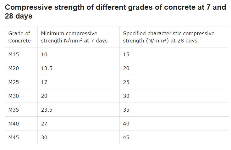
Table 14 – Different Grade Concrete Strengths (30)
The results are spilt into two categories: 100% OPC and 50% OPC AND 50% GGBS. There are four mix designs for each category and comparisons can be made between the two groups (Ref. Table 15 Mix Design and Associated Counterparts). The following mix designs correspond with each other for comparison:
| Original 100% OPC &% Recycled Aggregate | Counterpart 50% OPC & 50% GGBS & % Recycled aggregate | ||
| Mix Design 1 | 0% | Mix Design 5 | 0% |
| Mix Design 2 | 25% | Mix Design 6 | 25% |
| Mix Design 3 | 50% | Mix Design 7 | 50% |
| Mix Design 4 | 75% | Mix Design 8 | 75% |
Table 15 – Mix Designs and Associated Counterparts
8.1 Mix Design 1
The standard concrete mix was prepared for a strength of 20 N/mm². Therefore, after following the standard concrete making procedure it is expected that this batch would achieve its required goal. It can be seen from the results that the strength after 7 days was 15.84 N/mm². This was expected and is slightly higher than the required which indicates the batch mixed may have been slightly over strengthened. The concrete strength after 14 days was 20.33 N/mm². Having achieved the target strength after 14 days it is evident the mix was over strengthened and therefore the design could have been reduced. Mainly the OPC content or water content could have been reduced.
Having already obtained its target strength the 28 day test was to determine what the compressive strength the mix actually was. 22.48 N/mm² was the final strength of the batch and can be accepted for an intended 20 N/mm² concrete.
8.2 Mix Design 2
This was the first batch prepared of a modified mix. The aim of this batch was to determine the effect on the compressive strength of the concrete when having 25% of the standard aggregate are substituted with recycled aggregate. Testing was once again carried out at 7, 14 and 28 days.
The compressive strength of the batch at 7 days was 16.40 N/mm². This over achieved the standard requirements for a 20 N concrete at this early stage. This indicates that the mix was over designed. At this stage of testing the modified mix is stronger than the standard batch. This may be due to the presence of dried mortar already attached to the recycled aggregate particles.
At 14 days the batch achieved a strength of 18.17 N/mm². Already the modified batch has weakened in comparison to the standard mix. However, the batch has achieved the required strength for this time period.
The final compressive strength of the 25% recycled aggregate with 100 % OPC was 21.4 N/mm². Therefore, it can be concluded that the batch was a success even when 25% of the aggregate was substituted with recycled aggregate. Although the mix strengthened faster over a 7 day period the final result was weaker than a standard mix.
8.3 Mix Design 3
The second modified mix saw an increase in the quantity of recycled aggregate added to the mix design. The main focus of this batch was to see how it compared to the previous two mixes. It was expected that the batch would be stronger than the 25% mix since there were more particles with dried mortar attached.
The compressive strength at 7 days for this mix was 13.91 N/mm². This is clearly much weaker than the 25% and standard mix. Although it is weaker than the previous batches it has met the standard requirement of 13.5 N/mm² at 7 days. This indicates that the mix has the potential to reach the required target of 20 N/mm² at 28 days.
The result at 14 days was 17.22 N/mm². Once again the batch is weaker than the previous mixes. Not only is it weaker but it has also failed to reach the required 18 N/mm² for the 14 day time period. At this stage it is a good indicator whether the mix will meet its required strength as at 14 days the compressive strength should be 90% of its max strength.
The batch failed to reach its target by 28 days, having a compressive strength of 17.49 N/mm². It can be concluded that a batch of 50% recycled aggregate and 100% OPC failed. An increase in cement and/or water content would need to be added to achieve the required strength. However, this would be an extra cost and therefore unviable.
8.4 Mix Design 4
Having obtained the results for the 50% mix it was expected that this batch would not achieve its target. However, the increase in dried mortar within the mix might have a positive bearing on the batch.
The compressive strength after 7 days was 9.83 N/mm². This was an excellent indicator that the batch was under designed. Not only was the mix weaker than previous batches but it has failed to reach the required 13.5 N/mm² for the time period. The batch is 27% weaker than its expected strength.
The outcome for the 14 day compressive strength was inevitable. Having only achieved a strength of 13.41 N/mm² this batch is once again the weakest mix and also failing to meet the required 18 N/mm² at 14 days. This batch was 26% weaker than expected at this time period.
Having only obtained a max strength of 15.58 N/mm² the mix design has failed to reach its target of 20 N/mm². It can be concluded that a mix design of 75% recycled aggregate with 25% standard aggregate and 100% OPC cannot be accepted and can be deemed a failure. Therefore, it can be agreed that a mix design of 100% recycled aggregate with 100% OPC would be a waste of time when the previous trends are taken into consideration.
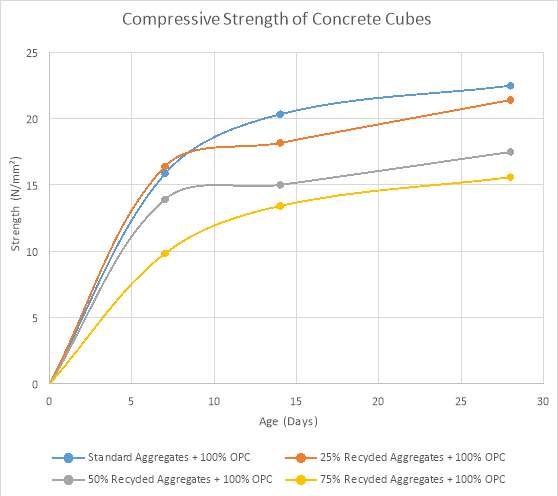
Table 16- Compressive Strengths of Mix Designs 1-4
8.5 Mix Design 5
Identical quantities of aggregate but different quantities of OPC and the addition of GGBS were used for mix designs 5-8. The aim of this set of results was to show what effect this had on the compressive strength of the concrete.
At 7 days the strength of the batch was 11.88 N/mm². This is weaker than the standard mix with 100% OPC. The batch also failed to meet the 13.5 N/mm² requirement at 7 days. This should indicate that the mix will fail the overall test. The batch failed by 12%.
The compressive strength at 14 days was 19.07 N/mm². Once again it is weaker than its corresponding batch but to a lesser degree. On the other hand it has surpassed the required 18 N/mm² at 14 days. This is a complete reversal of the results shown for 7 days and would suggest that the batch will actually acquire the 20 N/mm² strength.
After 28 days design mix 5 had surpassed the required 20 N/mm² strength by achieving a max compressive strength of 22.6 N/mm². This mix design of 50% GGBS, 50 % OPC and standard aggregate slightly surpassed it standard counterpart. This would indicate that the addition of GGBS has no effect on the design.
8.6 Mix Design 6
Similar to previous tests the aim of this batch was to examine how the addition of GGBS affects the compressive strength of the concrete.
After 7 days the compressive strength was 17.81 N/mm². This was an outstanding result and would have to be questioned. Not only has the cube exceeded the required strength after 7 days but it has also exceeded the strength required at 14 days. Therefore, it is no surprise that it is by far the strongest cube made. Further testing will highlight any discrepancies which may have occurred in the mixing of this batch.
The compressive strength after 14 days was 26.55 N/mm². Once again these results are exceptional. Only half ways through the curing process the batch has achieved and surpassed it required 20 N/mm². Further analysis will need to be carried out on this batch as the results attained are 47% stronger than expected. Perhaps an incorrect quantity of OPC or GGBS was added to the mix. .
Following on from its previous results, mix design 6 reached a max strength of 29.39 N/mm². Having observed its early trend of being a superior cube it was expected that this mix would be the strongest. However, the pouring of the mix design would have to be called into question as this mix design is nearly 40% stronger than its counterpart. If this is not the case and in fact the results are a true representation of the mix design then it is clear that 50% OPC, 50% GGBS with 75% standard aggregate and 25% recycled aggregate should be used in future projects.
8.7 Mix Design 7
This batch should be slightly weaker than the previous batch having gone on earlier results. However, since the previous batch was exceptional the results for this mix are uncertain and unpredictable.
After curing for 7 days the compressive strength was 13.45 N/mm². Just short of the required target this result resorts back to the original trend highlighted for Batch 1 to Batch 5. An acceptable result but still weaker than its counterpart batch with no GGBS added.
As expected after 14 days the compressive strength was 18.41 N/mm². Higher than the required strength and stronger than its counterpart batch it can be assumed at 14 days that the batch will acquire the required 20N strength by 28 days.
The max compressive strength of mix design 7 was 23.65 N/mm². Having achieved the required target it can be agreed that this mix design passed. However, this was unexpected as its counterpart failed to reach 20 N/mm². This would suggest that the addition of GGBS to the mix design caused an increase in strength.
8.8 Mix Design 8
This batch of concrete was estimated to fail after taking into account how its corresponding mix with no GGBS recorded.
The result recorded after 7 days was 13.06 N/mm². Having exceed its corresponding mix by 33% and nearly reaching the required strength of 13.5 N/mm² after 7 days it can be agreed that this mix design is acceptable.
After 14 days the compressive strength was 13.47 N/mm². Having only increase in strength by 3% instead of the expected 25% it can be assumed that this mix design will fail to reach the 20N strength.
Mix design 8 only obtained a maximum compressive strength of 16.06 N/mm² after 28 days. Once again a modified mix containing 75% recycled aggregate failed to reach the required strength. This was expected based on previous results as well as it corresponding counterpart also failing to reach its target.
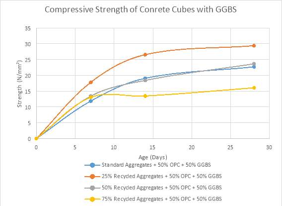
Table 17 – Compressive Strengths of Mix Designs 5-8
8.9 Results Summary
After mixing forty eight 100 mm X 100mm cubes the following conclusions can be made (See Appendix B for images of cube results)
- The compressive strength for all cubes increased at the expected rate over the 28 day curing period.
- An excess addition of recycled aggregate into a mix caused the strength to deplete. This is true for all cases except mix design 6 which is 25% recycled aggregate and 50% OPC with 50% GGBS which may have been incorrectly mixed.
- Mix Design 6 would have to be re-mixed to eliminate any suspicions of an error occurring.
- For mix designs with 100% OPC only two batches (mix designs 1 of 0% recycled and 2 of 25% recycled aggregate) reached the required 20 N/mm² strength. Whilst 3 mix designs (mix designs 5, 6, 7) containing 50% OPC and 50% GGBS surpassed the required 20 N/mm².
- It can be concluded that the addition of GGBS to a mix increases a mixes overall strength over a 28 day period. As well as more batches achieving the required strength, all mixes were stronger than their counterparts.
9.0 Pairc Uí Chaoimh Concrete Take-Off
Pairc Uí Chaoimh the home of Cork G.A.A. is currently undertaking is largest redevelopment to date. Large extensive works which includes near demolition of the existing stadium, construction of a new state of the art stadium with and increased capacity and a complete re-design of landscape of the surrounding areas. The total cost of the build is estimated by John Sisk construction is €80 million. There is no recycling of material from demolition to construction (31).
Objective:
Determine whether the use of recycled material in the construction of the surrounding areas would be viable and cost effective.
With the complete demolition of both North and South stands and the partial demolition of both terraces, it must be questioned what cost could have been saved if this material was saved? This includes both financial savings as well as carbon footprint reduction. Having obtained drawings from the existing stadium a concrete load take-off could be completed. The frame of the old development consisted of reinforced concrete. Each stand is comprised of 20 frames which support the stand. Each stand consists of approximately 5.5m³ of concrete. Therefore, it can be concluded that through the demolition of the supports for the stadiums, 225m³ of concrete could be reclaimed and recycled. Both stands and terraces consist of 60 threads which are constructed from insitu concrete slab. Therefore¸ for the entire the total quantity of concrete which could have been obtained from the threads is approx. 1700m³. With the inclusion of miscellaneous objects that brings the total concrete take-off for the stadium to approx. 2500m³ of concrete. (See Appendix C – Fig 1) (Illustrated in Fig 28)
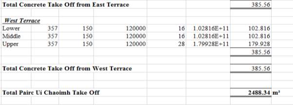
Figure 28- Extract from Pairc Uí Chaoimh Concrete Take-Off [E]
It can be agreed that the total amount of concrete which could have be saved and reused is substantial. Following on from the findings of this report (See section 7.9 – Results Summary) it can be concluded that recycled aggregate can only be used in 25% proportions for 20 N/mm2 concrete. For this reason recycled aggregate could only be used in footpaths and other low bearing constructions. The entire new build of the stadium would have to consist of 100% virgin aggregate.
The proposed design of the redeveloped landscape consists of a variety of exposed aggregate asphalt, concrete sets paving, asphalt, concrete grass paving 70% hard standing and several other materials. (See Appendix C and illustrated in Fig 29). The wide range of materials vary in depth but the majority are 100mm in thickness. All surfaces are calculated to this depth. (Note: Not all surfaces were taken into consideration as surfaces which needed a certain appearance could not use recycled aggregate e.g. natural stone paving). The total surface are of concrete landscaping required is approx. 20,000 m². At a depth of 100mm this equates to 2,000m³. It is clear that through the demolition of the existing stands there is enough aggregate for 100% of the concrete landscaping. However, to achieve the required 20 N/mm² strength for footpaths only 25% of recycled aggregate is needed (Ref. Fig 30 for 0% recycled aggregate).
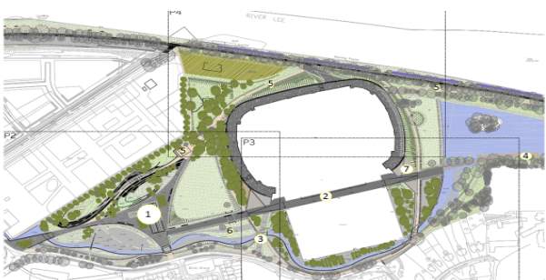
Figure 29- Marina Park Development [E]
Two options need to be taken into decision before a conclusion can be drawn. Option 1 – Dispose of 100% of rubble generated. Option 2 – Maintain 25% of rubble generated and dispose of 75%. Factors which were taken into consideration include distance to disposal site, machinery required, machinery size, cost for usage and operator cost. All costs were obtained from CESMM 4, a standard method of measurement (32). The total cost of disposing of 100% of the aggregate would be approx. €132,000. When costing option 2 several more factors have to be taken into consideration such as extra machinery and extra workers. The grand total of reusing 25% of rubble generated for the landscape would be approx. €115,000 (€99,000 to remove 75% of existing aggregate and €16,000 to process and recycled 25% of aggregate).
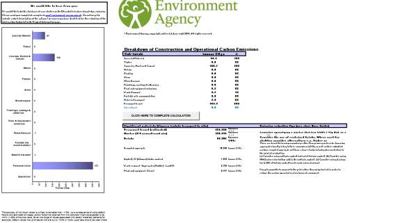
Figure 30. 0% Recycled aggregate [F]
Option 2 is cheaper by €17,000. However, when the scale of the project is taken into consideration the menial saving must be analysed. It is not worth the extra time required to sieve, crush and mix 25% of recycled aggregate. It is both unnecessary and uneconomical to carry out this procedure for a €80 million project just to save €17,000. This means that only 500m³ of recycled aggregate is needed. Only a fifth of total demolished aggregate is required for landscaping. This is a relatively small amount of aggregate required in comparison to what was taken. Therefore the viability of using recycled aggregate for this project would be brought into question (Ref. Fig 31 for 25% recycled aggregate).

Figure 31 – 25% Recycled aggregate[F]
9.1 Recommendations for Pairc Uí Chaoimh
Although the use of recycled aggregate is not currently viable for this project, it must be questioned what incentives/taxes could be put in place for this option to become viable.
One option which may promote the use of recycled aggregate is for the Irish government to impose a tax on virgin aggregate. This is already a success in other European countries (See Section 3.8 – Aggregate Tax). If a tax was imposed on virgin aggregate the contractors would be more inclined to reuse rather than discard. This would be the case in particular if the tax was severe and would have a serious cost implication on the project.
Another recommendation for Pairc Uí Chaoimh development is the introduction of a CO2 tax. Similar to an aggregate tax, a CO2 taxmust be imposed by the Irish government. However, unlike an aggregate tax this would have a greater consequence. The difference in CO2 emissions between Option 1 and Option 2 is significant (See Appendix C – Carbon Calculator). Therefore, an introduction of a tax on CO2 emissions would have extreme implications on the cost of the development.
A final option is to use more recycled aggregate in nearby projects. It is suggested that the Marina Park development walkways will extend to Cork City, approx. 3 km away (31). If this is the case, a far greater supply of recycled aggregate would be required. Therefore the use of recycled material would be of a greater financial benefit and would appeal more to the developers. Since there is no immediate action being taken on implementing taxes on CO2 or virgin aggregates it can be concluded that this final recommendation would be the method to apply to the Pairc Uí Chaoimh development.
10.0 Conclusion
The data acquired through both practical and literary research highlights that recycled aggregate (R.A.) can be used as a substitute for virgin materials within a concrete mix design. However, its use is limited to low bearing surfaces such as footpaths and paving. This is clearly represented in the findings as it shows that a maximum of 25% R.A. and 50% R.A. with 100% OPC and 50% OPC and 50% GGBS respectively can be used. This is to ensure the minimum concrete strength of 20 N/mm² for low bearing surfaces is achieved. The quality and consistency of R.A. is a major concern thus eliminating its potential use in structural concrete.
Another aspect which is vital for the increased usage of R.A. in concrete mix designs is its ability to create a more sustainable project. Through the use of carbon calculators the findings show that by using R.A. the carbon footprint of a development is reduced which leads to the reduction of extracting virgin materials. This has a positive domino effect as the cost and carbon footprint decreases whilst the supply of a finite material is maintained. The use of R.A. is extremely beneficial to projects where virgin aggregate is in short supply or difficult to obtain. Large demolition and construction (C&D) builds are projects which would be most benefited by using R.A. For example, projects similar to Pairc Uí Chaoimh as highlighted previously.
It is clearly shown that tax incentives are key to promoting the use of R.A. these generous initiatives provide businesses with a reason to use R.A. within their design. Not only are the gains previously mentioned accomplished but an immediate financial gain can be seen. A case and point is Denmark where the use of R.A. has increased from 12% usage to 94% from 1985 to 2004. This positive effect of this initiative can also be seen in Sweden but to a lesser extent.
The feasibility of using other recycled materials such as glass or rubber would have to been investigated and the maximum compressive strength established. However, if these materials could be used then a new alleyway for R.A. could be established. As well as low bearing surfaces R.A. could be used in decorative features such as polished concrete floors and ornaments.
The positive benefits of R.A. on the environment is noticed through its reduction in carbon footprint. Not only is this better for the environment but it also helps channel a development towards BREEAM guidelines and specifications. This is clearly shown earlier in the report. As well as this the use of R.A. lowers a developments embodied energy and provides a sustainable material for the future.
To conclude, not only is the use is of recycled aggregate cost effective and environmentally beneficial but it is also a viable and suitable replacement of virgin aggregate in the construction industry. With other European countries paving the way in sustainable materials and more and more companies in Ireland beginning to see the benefits of using recycled materials it is only a matter of time before the use of recycled aggregate is cemented in standard concrete mix designs.
11.0 Bibliography
1.CN. Concrete Network. Concrete Network. [Online] https://www.concretenetwork.com/concrete-history/.
2. BCA. Portland Cement – British Cement Association .
3. Eurocodes. Eurocodes, IS EN 206-1.
4. Meyers, C. Recycled Materials in Concrete. Developments in the Formulation and Reinforcement of Concrete. s.l. : CRC Press LLC., 2008.
5. Standards, British. Specification for aggregates from natural sources for concrete.
6. RIAI. Conservation of Buildings. 2010. 3 .
7. Solderholm, Patrick. Science for Environment Policy. 2011.
8. http://ecosmartconcrete.com/docs/trmehta01.pdf. [Online]
9. http://www.sciencedirect.com/science/article/pii/S0958946509000031. [Online]
10. Ltd, The Irish Concrete Federation. The New Concrete Standards – An Introduction to EN 206-1. 2004.
11. Brundtland, Gro Harlem. Our Common Future. 1989.
12. Behera, Monalisa. Construction and Building Materials. Tarragona: s.n., 2008.
13.I.C.E. Designing Buildings. ICE -BRE. [Online] https://www.designingbuildings.co.uk/Sustainable_materials.
14. Engineers, Institution of Structural. Sustainability Briefings. London: s.n., 2011.
15. Agency, Environment. Carbon Calculator.
16. Colin MacDougal, PhD, P.Eng. The Jounal of Green Building . Natural Building Materials in Mainstream Construction: Lessons from the U. K. . Summer 2008, 2008, Vol. 3, 3.
17. Vincent Mathias, Sedran, Thierry and de Larrard, Francois . Recycling Reclaimed Asphalt Pavement in Concrete Roads. [book auth.] RILEM. Use of Recycled Materials in Buildings and Structures. Barcelona: s.n., 2004.
18. Jr., Gilpin R. Robinson. Recycling of construction debris as aggregate in the Mid-Atlantic Region, USA.
19. Global, BRE. BREEAM Scheme Document SD 5052. s.l.: BRE Global Ltd., 2008.
20. Materials and Structures. RILEM. s.l.: Springer Netherlands, 2017, Vol. 50. 1359-5997.
21. Rawlinson, S., Weight, D. Sustainability: Embodied carbon, Building,. 2007.
22. CRH. 2015 Sustainability Report. 2015.
23.http://ec.europa.eu/environment/integration/research/newsalert/pdf/262na1_en.pdf. [Online]
24. (1) http://matse1.matse.illinois.edu/concrete/bm.html. [Online]
25. . http://www.cement.org/cement-concrete-basics/how-cement-is-made. [Online]
26. http://www.ehow.com/info_12194581_importance-sand-concrete.html. [Online]
27. Solutions, QEM. QEM Solutions. QEM Solutions. [Online] QEM Solutions. www.qemsolutions.com.
28. Peatfield, A.E. Practical Concreting. s.l.: The English Universities Press Ltd., 1970.
29. Blackledge, G.F. Concrete Practice. s.l.: Cement and Concrete Association, 1987.
30. Compressive Strength of Concrete Cubes. Constructor, The.
31. Leen, Tony. Irish Examiner. Irish Examiner. [Online]
32. Thomas Telford. CESMM4 Standard Method of Measurement. s.l.: The Institute of Civil Engineers, 2012.
33. I.C.S. The Irish Concrete Society . The Irish Concrete Society . [Online] hhtp://http://www.concrete.ie/concrete.
Referencing of Images
[A] – www.googleimages.com
[B] – Global, BRE. BREEAM Scheme Document SD 5052. s.l.: BRE Global Ltd., 2008.
[C] – CRH. 2015 Sustainability Report. 2015.
[D] – Eurocodes. Eurocodes, IS EN 206-1.
[E] – Authors’ own images
[F] – Agency, Environment. Carbon Calculator.
Appendices
Appendix A (Aggregate Mix Design)
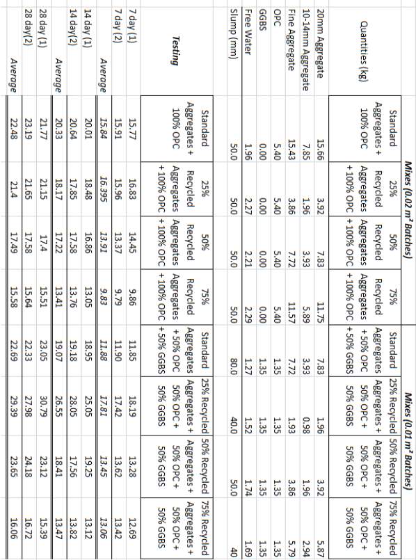
Figure 32 – Concrete Mix Data
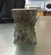
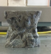
Appendix B (Crushed Cube Cores)
100% OPC
Standard Mix
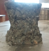
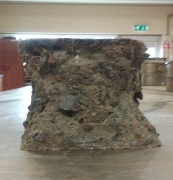
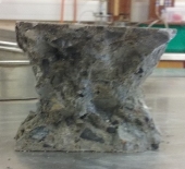
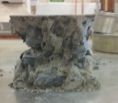
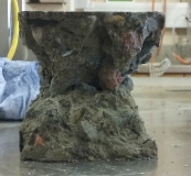
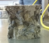
50% Recycled Aggregate
Figure 33- Pairc Uí Chaoimh Layout out plan 50% Recycled Aggregate
50% Recycled Aggregate
75% Recycled Aggregate
50% OPC & 50% GGBS
25% Recycled Aggregate
Standard Mix
25% Recycled Aggregate
50% Recycled Aggregate
75% Recycled Aggregate
Appendix C (Pairc Uí Chaoimh)
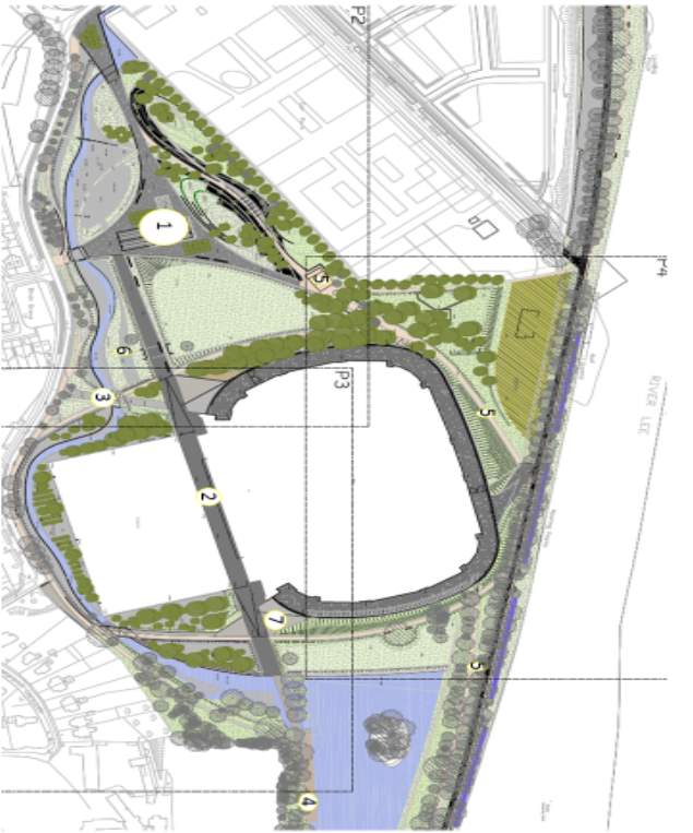
Figure 34– Pairc Uí Chaoimh Layout out plan
Table 18 – Concrete Take off for Main standFigure 35- Pairc Uí Chaoimh Layout out plan
Table 19 – Concrete Take off for Main stand
Table 20 – Concrete Take off for Main stand
Table 21 – Load take off for North StandTable 22 – Concrete Take off for Main standFigure 36- Pairc Uí Chaoimh Layout out plan
Table 23 – Concrete Take off for Main standFigure 37- Pairc Uí Chaoimh Layout out plan
Table 24 – Concrete Take off for Main stand
Table 25 – Concrete Take off for Main stand
Table 26 – Load take off for North StandTable 27 – Concrete Take off for Main stand
Table 28 – Concrete Take off for Main stand
Table 29 – Load take off for North Stand
Table 30 – Load take off for North Stand
Table 31 – Load take off for North StandTable 32 – Concrete Take off for Main stand
Table 33 – Concrete Take off for Main stand
Table 34 – Load take off for North StandTable 35 – Concrete Take off for Main standFigure 38- Pairc Uí Chaoimh Layout out plan
Table 36 – Concrete Take off for Main standFigure 39- Pairc Uí Chaoimh Layout out plan
Table 37 – Concrete Take off for Main stand
Table 38 – Concrete Take off for Main stand
Table 39 – Load take off for North StandTable 40 – Concrete Take off for Main standFigure 40- Pairc Uí Chaoimh Layout out plan
Table 41 – Concrete Take off for Main standFigure 41- Pairc Uí Chaoimh Layout out plan
Table 42 – Concrete Take off for Main stand
Table 43 – Concrete Take off for Main stand
Table 44 – Load take off for North StandTable 45 – Concrete Take off for Main stand
Table 46 – Concrete Take off for Main stand
Table 47 – Load take off for North Stand
Table 48 – Load take off for North Stand
Table 49 – Load take off for North StandTable 50 – Concrete Take off for Main stand
Table 51 – Concrete Take off for Main stand
Table 52 – Load take off for North StandTable 53 – Concrete Take off for Main stand
Table 54 – Concrete Take off for Main stand
Table 55 – Load take off for North Stand
Table 56 – Load take off for North Stand
Table 57 – Load take off for North Stand
Table 58 – Load take off for North Stand
Table 59 – Load take off for North Stand
Table 60 – Load take off for North Stand
Table 61 – Load take off for North StandTable 62 – Concrete Take off for Main stand
Table 63 – Concrete Take off for Main stand
Table 64 – Load take off for North StandTable 65 – Concrete Take off for Main stand
Table 66 – Concrete Take off for Main stand
Table 67 – Load take off for North Stand
Table 68 – Load take off for North Stand
Table 69 – Load take off for North StandTable 70 – Concrete Take off for Main stand
Table 71 – Concrete Take off for Main stand
Table 72 – Load take off for North StandTable 73 – Concrete Take off for Main standFigure 42- Pairc Uí Chaoimh Layout out plan
Table 18 – Concrete Take off for Main standFigure 43- Pairc Uí Chaoimh Layout out plan
Table 19 – Concrete Take off for Main stand
Table 20 – Concrete Take off for Main stand
Table 21 – Load take off for North StandTable 22 – Concrete Take off for Main standFigure 44- Pairc Uí Chaoimh Layout out plan
Table 23 – Concrete Take off for Main standFigure 45- Pairc Uí Chaoimh Layout out plan
Table 24 – Concrete Take off for Main stand
Table 25 – Concrete Take off for Main stand
Table 26 – Load take off for North StandTable 27 – Concrete Take off for Main stand
Table 28 – Concrete Take off for Main stand
Table 29 – Load take off for North Stand
Table 30 – Load take off for North Stand
Table 31 – Load take off for North StandTable 32 – Concrete Take off for Main stand
Table 33 – Concrete Take off for Main stand
Table 34 – Load take off for North StandTable 35 – Concrete Take off for Main standFigure 46- Pairc Uí Chaoimh Layout out plan
Table 36 – Concrete Take off for Main standFigure 47- Pairc Uí Chaoimh Layout out plan
Table 37 – Concrete Take off for Main stand
Table 38 – Concrete Take off for Main stand
Table 39 – Load take off for North StandTable 40 – Concrete Take off for Main standFigure 48- Pairc Uí Chaoimh Layout out plan
Table 41 – Concrete Take off for Main standFigure 49- Pairc Uí Chaoimh Layout out plan
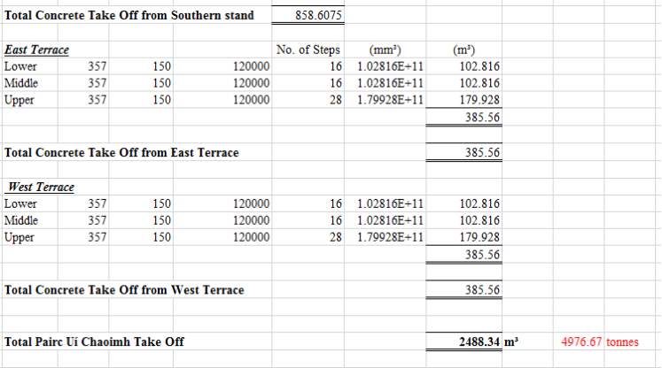
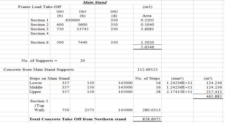
Table 2. Load take off
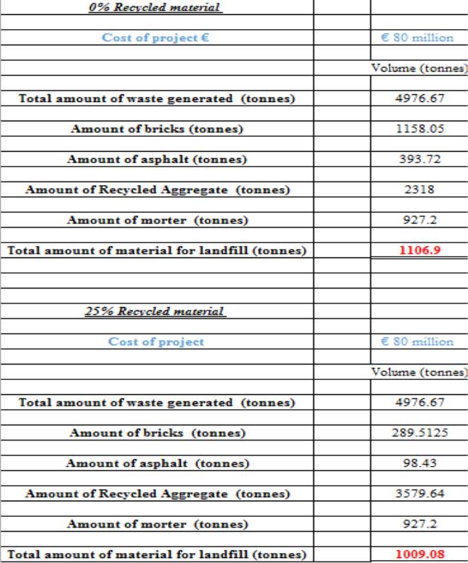
Table 3.Volume of material
Table 128- Total Volume of concrete
Table 129- Total Volume of concrete
Table 130- Total Volume of concrete
Table 131- Total Volume of concrete
Table 132- Total Volume of concrete
Table 133- Total Volume of concrete
Table 134- Total Volume of concrete
Table 135- Total Volume of concrete
Table 136- Total Volume of concrete
Table 137- Total Volume of concrete
Table 138- Total Volume of concrete
Table 139- Total Volume of concrete
Table 140- Total Volume of concrete
Table 141- Total Volume of concrete
Table 142- Total Volume of concrete
Table 143- Total Volume of concrete
Table 144- Total Volume of concrete
Table 145- Total Volume of concrete
Table 146- Total Volume of concrete
Table 147- Total Volume of concrete
Table 148- Total Volume of concrete
Table 149- Total Volume of concrete
Table 150- Total Volume of concrete
Table 151- Total Volume of concrete
Table 152- Total Volume of concrete
Table 153- Total Volume of concrete
Table 154- Total Volume of concrete
Table 155- Total Volume of concrete
Table 124- Total Volume of concrete
Table 125- Total Volume of concrete
Table 126- Total Volume of concrete
Table 127- Total Volume of concrete
Table 129- Total Volume of concrete
Table 130- Total Volume of concrete
Table 131- Total Volume of concrete
Table 132- Total Volume of concrete
Table 133- Total Volume of concrete
Table 134- Total Volume of concrete
Table 135- Total Volume of concrete
Table 136- Total Volume of concrete
Table 137- Total Volume of concrete
Table 138- Total Volume of concrete
Table 139- Total Volume of concrete
Table 140- Total Volume of concrete
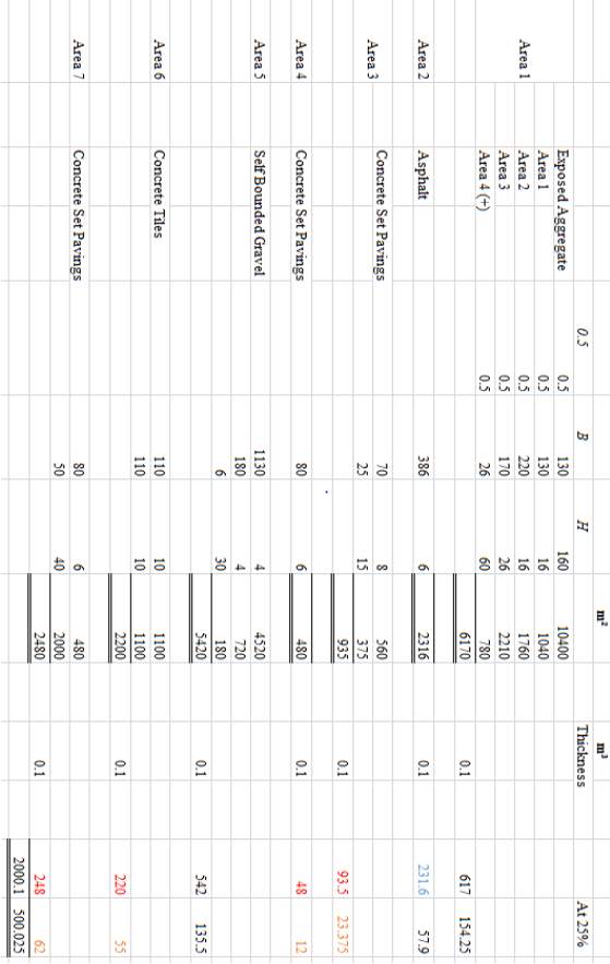
Table 4.Total Volume of concrete
Table 157- 0% Recycled Aggregate
Table 158– 0% Recycled Aggregate
Table 159- 0% Recycled Aggregate
Table 160- 0% Recycled Aggregate
Table 161- 0% Recycled Aggregate
Table 162- 0% Recycled Aggregate
Table 163- 0% Recycled Aggregate
Table 164- 0% Recycled Aggregate
Table 165- 0% Recycled Aggregate
Table 166- 0% Recycled Aggregate
Table 167- 0% Recycled Aggregate
Table 168- 0% Recycled Aggregate
Table 169- 0% Recycled Aggregate
Table 170- 0% Recycled Aggregate
Table 171- 0% Recycled Aggregate
Table 172- 0% Recycled Aggregate
Table 173- 0% Recycled Aggregate
Table 174- 0% Recycled Aggregate
Table 175- 0% Recycled Aggregate
Table 176- 0% Recycled Aggregate
Table 177- 0% Recycled Aggregate
Table 178- 0% Recycled Aggregate
Table 179- 0% Recycled Aggregate
Table 180- 0% Recycled Aggregate
Table 181- 0% Recycled Aggregate
Table 182- 0% Recycled Aggregate
Table 183- 0% Recycled Aggregate
Table 184- 0% Recycled Aggregate
Table 185- 0% Recycled Aggregate
Table 186- 0% Recycled Aggregate
Table 187- 0% Recycled Aggregate
Table 188- 0% Recycled Aggregate
Table 157- 0% Recycled Aggregate
Table 158- 0% Recycled Aggregate
Table 159- 0% Recycled Aggregate
Table 160- 0% Recycled Aggregate
Table 161- 0% Recycled Aggregate
Table 162- 0% Recycled Aggregate
Table 163- 0% Recycled Aggregate
Table 164- 0% Recycled Aggregate
Table 165- 0% Recycled Aggregate
Table 166- 0% Recycled Aggregate
Table 167- 0% Recycled Aggregate
Table 168- 0% Recycled Aggregate
Table 169- 0% Recycled Aggregate
Table 170- 0% Recycled Aggregate
Table 171- 0% Recycled Aggregate
Table 172- 0% Recycled Aggregate
Table 173- 0% Recycled Aggregate
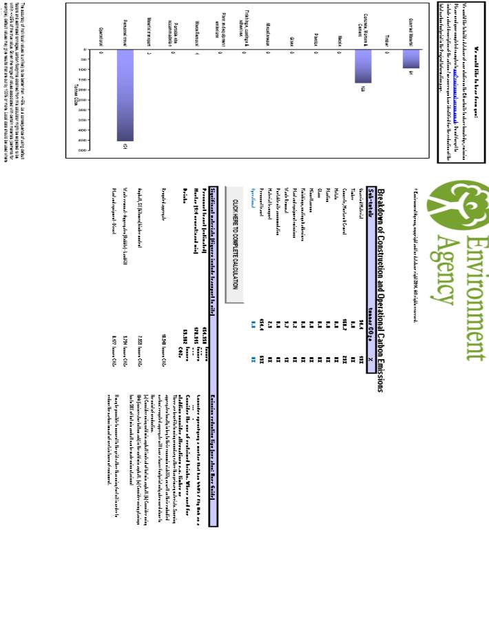
Table 5. 0% Recycled aggregate
Table 190 – 25% Recycled Aggregate
Table 191 – 25% Recycled Aggregate
Table 192 – 25% Recycled Aggregate
Table 193 – 25% Recycled Aggregate
Table 194 – 25% Recycled Aggregate
Table 195 – 25% Recycled Aggregate
Table 196 – 25% Recycled Aggregate
Table 197 – 25% Recycled Aggregate
Table 198 – 25% Recycled Aggregate
Table 199 – 25% Recycled Aggregate
Table 200 – 25% Recycled Aggregate
Table 201 – 25% Recycled Aggregate
Table 202 – 25% Recycled Aggregate
Table 203 – 25% Recycled Aggregate
Table 204 – 25% Recycled Aggregate
Table 205 – 25% Recycled Aggregate
Table 206 – 25% Recycled Aggregate
Table 207 – 25% Recycled Aggregate
Table 208 – 25% Recycled Aggregate
Table 209 – 25% Recycled Aggregate
Table 210 – 25% Recycled Aggregate
Table 211 – 25% Recycled Aggregate
Table 212 – 25% Recycled Aggregate
Table 213 – 25% Recycled Aggregate
Table 214 – 25% Recycled Aggregate
Table 215 – 25% Recycled Aggregate
Table 216 – 25% Recycled Aggregate
Table 217 – 25% Recycled Aggregate
Table 218 – 25% Recycled Aggregate
Table 219 – 25% Recycled Aggregate
Table 220 – 25% Recycled Aggregate
Table 221 – 25% Recycled Aggregate
Table 190 – 25% Recycled Aggregate
Table 191 – 25% Recycled Aggregate
Table 192 – 25% Recycled Aggregate
Table 193 – 25% Recycled Aggregate
Table 194 – 25% Recycled Aggregate
Table 195 – 25% Recycled Aggregate
Table 196 – 25% Recycled Aggregate
Table 197 – 25% Recycled Aggregate
Table 198 – 25% Recycled Aggregate
Table 199 – 25% Recycled Aggregate
Table 200 – 25% Recycled Aggregate
Table 201 – 25% Recycled Aggregate
Table 202 – 25% Recycled Aggregate
Table 203 – 25% Recycled Aggregate
Table 204 – 25% Recycled Aggregate
Table 205 – 25% Recycled Aggregate
Table 206 – 25% Recycled Aggregate
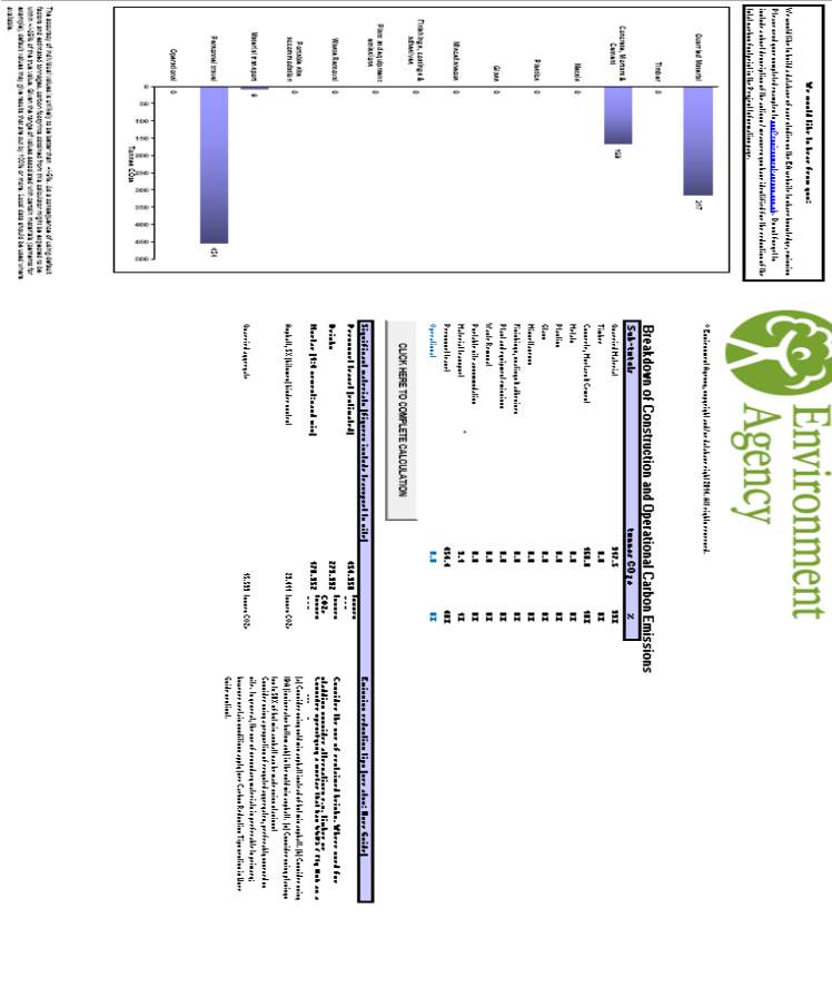
Table 6. 25% Recycled aggregate
Table 223 – Cost of Disposal
Table 224 – Cost of Disposal
Table 225 – Cost of Disposal
Table 226 – Cost of Disposal
Table 227 – Cost of Disposal
Table 228 – Cost of Disposal
Table 229 – Cost of Disposal
Table 230 – Cost of Disposal
Table 231 – Cost of Disposal
Table 232 – Cost of Disposal
Table 233 – Cost of Disposal
Table 234 – Cost of Disposal
Table 235 – Cost of Disposal
Table 236 – Cost of Disposal
Table 237 – Cost of Disposal
Table 238 – Cost of Disposal
Table 239 – Cost of Disposal
Table 240 – Cost of Disposal
Table 241 – Cost of Disposal
Table 242 – Cost of Disposal
Table 243 – Cost of Disposal
Table 244 – Cost of Disposal
Table 245 – Cost of Disposal
Table 246 – Cost of Disposal
Table 247 – Cost of Disposal
Table 248 – Cost of Disposal
Table 249 – Cost of Disposal
Table 250 – Cost of Disposal
Table 251 – Cost of Disposal
Table 252 – Cost of Disposal
Table 253 – Cost of Disposal
Table 254 – Cost of Disposal
Table 223 – Cost of Disposal
Table 224 – Cost of Disposal
Table 225 – Cost of Disposal
Table 226 – Cost of Disposal
Table 227 – Cost of Disposal
Table 228 – Cost of Disposal
Table 229 – Cost of Disposal
Table 230 – Cost of Disposal
Table 231 – Cost of Disposal
Table 232 – Cost of Disposal
Table 233 – Cost of Disposal
Table 234 – Cost of Disposal
Table 235 – Cost of Disposal
Table 236 – Cost of Disposal
Table 237 – Cost of Disposal
Table 238 – Cost of Disposal
Table 239 – Cost of Disposal
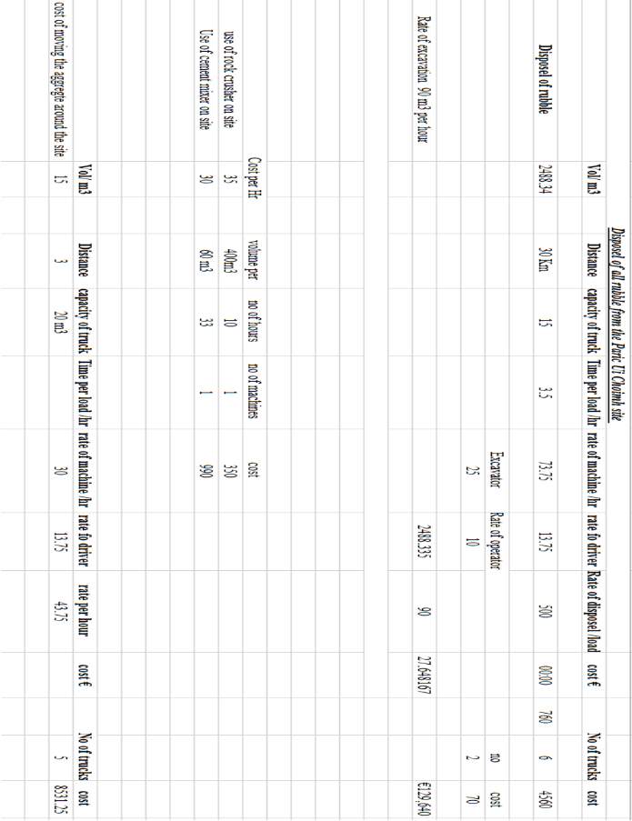
Table 7. Cost of Disposel
Appendix D (Risk Assessment and Method Statement)
Safety Method Statement and Risk Assessment
| Work Activity/Task:Concrete Cube Testing | Project Name/No: Recycled Material in Concrete | |
| Location:A125, Cork Institute of Technology, Bishopstown, Cork | Date :10/02/2017
Rev: A |
|
| Research Supervisor: Dr. Mary Moloney | Contact : 021-432 ???? | |
| Technical Officer: Maggie Shorten | Contact : 021-432 ???? | |
| Research Student: Gerard Whelton | Contact :086 – 2640624 | |
| Research Student: Colin Meaney | Contact :086-2617215 | |
| Building Representative: | Contact : | |
| Project/Work Scope:The proposed works involves the mixing, pouring and testing of concrete cubes using different recycled materials (glass, rubber, recycled aggregate and gravel). | ||
| Work tem | Job Step | Method |
| 1 | Wearing of PPE. |
All PPE must be worn and fitted correctly before entering the lab. PPE includes steel toe capped boots, dust mask, gloves (10-gauge Cotton/Poly Knit with Latex Palm), and safety glasses. Ensure all PPE are in good condition and marked with the CE mark. |
| 2 | Turning on of machinery. | Plug in cement mixer. Place in ideal location without causing an obstruction or hazard. |
| 3 | Addition and mixing of standard concrete materials. | Place materials near cement mixer. Using a shovel pour the required amount of cement into the cement mixer. Using a shovel place the required amount of sand and gravel into the cement mixer. Using a bucket pour the required amount of water into the cement mixer. Leave materials mix for a period of time. |
| 4 | Pouring of standard mix concrete into concrete test cubes. | Tip the cement mixer content into a wheel barrow and move to the location where concrete test cubes moulds are. Using a shovel fill the test cube mould half ways with the concrete mix. Using a tamping rod, compact the concrete mix. Fill the remainder of the test cube mould with the concrete mix using a shovel. Repeat tamping process. Repeat for three more test cubes. Place cubes in secure location to allow the concrete to set. |
| 5 | Washing of the cement mixer. | Move the cement mixer outdoors or to the nearest washing point. Using buckets of water or a hose wash the interior of the machine. Remove water by tipping the cement mixer. Move the cement mixer back indoors to its original position in preparation for a fresh batch of mixing. |
| 6 | Addition and mixing of recycled concrete mix 1 (glass) materials. | Ensure PPE are being worn when handling glass. Place materials near cement mixer. Using a shovel pour the required amount of cement into the cement mixer. Using a shovel place the required amount of sand and glass into the cement mixer. Using a bucket pour the required amount of water into the cement mixer. Leave materials mix for a period of time. |
| 7 | Pouring of recycled mix 1 (glass) into concrete test cubes. | Tip the cement mixer content into a wheel barrow and move to location where concrete test cubes moulds are. Using a shovel fill the test cube mould half ways with the concrete mix. Using a tamping rod, compact the concrete mix. Fill the remainder of the test cube moulds with concrete mix using a shovel. Repeat tamping process. Repeat for four more test cubes. Place cubes in secure location to allow the concrete to set. |
| 8 | Washing of the cement mixer. | Move the cement mixer outdoors or to the nearest washing point. Using buckets of water or a hose wash the interior of the machine. Remove the water by tipping the cement mixer. Move the cement mixer back in doors to its original position in preparation for a fresh batch of mixing. |
| 9 | Addition and mixing of recycled concrete mix 2 (rubber) materials. | Ensure PPE is worn when handling material. Place materials near cement mixer. Using a shovel pour the required amount of cement into the cement mixer. Using a shovel place the required amount of sand and rubber into the cement mixer. Using a bucket pour the required amount of water into the cement mixer. Leave materials mix for a period of time. |
| 10 | Pouring of recycled mix 2 (rubber) into concrete test cubes. | Tip the cement mixer content into a wheel barrow and move to location where concrete test cubes moulds are. Using a shovel fill the test cube half ways with the concrete mix. Using a tamping rod, compact the cement mix. Fill the remainder of the test cube moulds with concrete mix using a shovel. Repeat tamping process. Repeat for three more test cubes. Place cubes in secure location to allow the concrete to set. |
| 11 | Washing of the cement mixer. | Move the cement mixer outdoors or to the nearest washing point. Using buckets of water or a hose wash the interior of the machine. Remove the water by tipping the cement mixer. Move the cement mixer back in doors to its original position in preparation for a fresh batch of mixing. |
| 12 | Sieving of recycled aggregate | Place recycled aggregate sample into a tray. Sort range of sieves from smallest to largest starting at the bottom. Pour sample into sieves and place cover on top. Carry assortment of sieves and place onto shaker. Turn on shaker for appropriate length of time. Remove sieves and place on counter. Place desired aggregate size in separate container and discard undesired sizes. |
| 13 | Crushing Test | Ensure PPE are being worn. Place sample of desired aggregate in crushing test apparatus mould. Place the aggregate in over three layers and tamping 25 times after each layer. Place mould in crushing machine and fasten in place. Turn on machine. After 10 minutes turn of machine. Remove mould and sieve contents through 2.36mm sieve. Carry out necessary calculations to determine the crushing value of the aggregate. |
| 14 | Addition and mixing of recycled concrete mix 3 (25% recycled aggregate and 100% Ordinary Portland Cement) materials. | Place materials near cement mixer. Using a shovel pour the required amount of cement (100% Ordinary Portland Cement) into the cement mixer. Using a shovel place the required amount of sand and 25% recycled aggregate into the cement mixer. Using a bucket pour the required amount of water into the cement mixer. Leave materials mix for a period of time. |
| 15 | Pouring of recycled mix 3 (25 % recycled aggregate and 100% Ordinary Portland Cement) into concrete test cubes. | Tip the cement mixer content into a wheel barrow and move to location where concrete test cubes moulds are. Using a shovel fill the test cube half ways with the concrete mix. Using a tamping rod, compact the cement mix. Fill the remainder of the test cube moulds with concrete mix using a shovel. Repeat tamping process. Repeat for three more test cubes. Place cubes in secure location to allow the concrete to set. |
| 16 | Washing of the cement mixer. | Move the cement mixer outdoors or to the nearest washing point. Using buckets of water or a hose wash the interior of the machine. Remove the water by tipping the cement mixer. Move the cement mixer back in doors to its original position in preparation for a fresh batch of mixing. |
| 17 | Addition and mixing of recycled concrete mix 4 (50% recycled aggregate and 100% Ordinary Portland Cement) materials. | Place materials near cement mixer. Using a shovel pour the required amount of cement (100% Ordinary Portland Cement) into the cement mixer. Using a shovel place the required amount of sand and 50% recycled aggregate into the cement mixer. Using a bucket pour the required amount of water into the cement mixer. Leave materials mix for a period of time. |
| 18 | Pouring of recycled mix 4 (50 % recycled aggregate and 100% Ordinary Portland Cement) into concrete test cubes. | Tip the cement mixer content into a wheel barrow and move to location where concrete test cubes moulds are. Using a shovel fill the test cube half ways with the concrete mix. Using a tamping rod, compact the cement mix. Fill the remainder of the test cube moulds with concrete mix using a shovel. Repeat tamping process. Repeat for three more test cubes. Place cubes in secure location to allow the concrete to set. |
| 19 | Washing of the cement mixer. | Move the cement mixer outdoors or to the nearest washing point. Using buckets of water or a hose wash the interior of the machine. Remove the water by tipping the cement mixer. Move the cement mixer back in doors to its original position in preparation for a fresh batch of mixing. |
| 20 | Addition and mixing of recycled concrete mix 5 (75% recycled aggregate and 100% Ordinary Portland Cement) materials. | Place materials near cement mixer. Using a shovel pour the required amount of cement (100% Ordinary Portland Cement) into the cement mixer. Using a shovel place the required amount of sand and 75% recycled aggregate into the cement mixer. Using a bucket pour the required amount of water into the cement mixer. Leave materials mix for a period of time. |
| 21 | Pouring of recycled mix 5 (75 % recycled aggregate and 100% Ordinary Portland Cement) into concrete test cubes. | Tip the cement mixer content into a wheel barrow and move to location where concrete test cubes moulds are. Using a shovel fill the test cube half ways with the concrete mix. Using a tamping rod, compact the cement mix. Fill the remainder of the test cube moulds with concrete mix using a shovel. Repeat tamping process. Repeat for three more test cubes. Place cubes in secure location to allow the concrete to set. |
| 22 | Washing of the cement mixer. | Move the cement mixer outdoors or to the nearest washing point. Using buckets of water or a hose wash the interior of the machine. Remove the water by tipping the cement mixer. Move the cement mixer back in doors to its original position in preparation for a fresh batch of mixing. |
| 23 | Addition and mixing of recycled concrete mix 6 (25% recycled aggregate and 50% Ordinary Portland Cement and 50% GGBS) materials. | Place materials near cement mixer. Using a shovel pour the required amount of cement (50% Ordinary Portland Cement and 50% GGBS) into the cement mixer. Using a shovel place the required amount of sand and 25% recycled aggregate into the cement mixer. Using a bucket pour the required amount of water into the cement mixer. Leave materials mix for a period of time. |
| 24 | Pouring of recycled mix 5 (25 % recycled aggregate and 50% Ordinary Portland Cement and 50% GGBS) into concrete test cubes. | Tip the cement mixer content into a wheel barrow and move to location where concrete test cubes moulds are. Using a shovel fill the test cube half ways with the concrete mix. Using a tamping rod, compact the cement mix. Fill the remainder of the test cube moulds with concrete mix using a shovel. Repeat tamping process. Repeat for three more test cubes. Place cubes in secure location to allow the concrete to set. |
| 25 | Washing of the cement mixer. | Move the cement mixer outdoors or to the nearest washing point. Using buckets of water or a hose wash the interior of the machine. Remove the water by tipping the cement mixer. Move the cement mixer back in doors to its original position in preparation for a fresh batch of mixing. |
| 26 | Addition and mixing of recycled concrete mix 7 (50% recycled aggregate and 50% Ordinary Portland Cement and 50% GGBS) materials. | Place materials near cement mixer. Using a shovel pour the required amount of cement (50% Ordinary Portland Cement and 50% GGBS) into the cement mixer. Using a shovel place the required amount of sand and 50% recycled aggregate into the cement mixer. Using a bucket pour the required amount of water into the cement mixer. Leave materials mix for a period of time. |
| 27 | Pouring of recycled mix 7 (50 % recycled aggregate and 50% Ordinary Portland Cement and 50% GGBS) into concrete test cubes. | Tip the cement mixer content into a wheel barrow and move to location where concrete test cubes moulds are. Using a shovel fill the test cube half ways with the concrete mix. Using a tamping rod, compact the cement mix. Fill the remainder of the test cube moulds with concrete mix using a shovel. Repeat tamping process. Repeat for three more test cubes. Place cubes in secure location to allow the concrete to set. |
| 28 | Washing of the cement mixer. | Move the cement mixer outdoors or to the nearest washing point. Using buckets of water or a hose wash the interior of the machine. Remove the water by tipping the cement mixer. Move the cement mixer back in doors to its original position in preparation for a fresh batch of mixing. |
| 29 | Addition and mixing of recycled concrete mix 8 (75% recycled aggregate and 50% Ordinary Portland Cement and 50% GGBS) materials. | Place materials near cement mixer. Using a shovel pour the required amount of cement (50% Ordinary Portland Cement and 50% GGBS) into the cement mixer. Using a shovel place the required amount of sand and 75% recycled aggregate into the cement mixer. Using a bucket pour the required amount of water into the cement mixer. Leave materials mix for a period of time. |
| 30 | Pouring of recycled mix 8 (75 % recycled aggregate and 50% Ordinary Portland Cement and 50% GGBS) into concrete test cubes. | Tip the cement mixer content into a wheel barrow and move to location where concrete test cubes moulds are. Using a shovel fill the test cube half ways with the concrete mix. Using a tamping rod, compact the cement mix. Fill the remainder of the test cube moulds with concrete mix using a shovel. Repeat tamping process. Repeat for three more test cubes. Place cubes in secure location to allow the concrete to set. |
| 31 | Washing of the cement mixer. | Move the cement mixer outdoors or to the nearest washing point. Using buckets of water or a hose wash the interior of the machine. Remove the water by tipping the cement mixer. |
| 32 | Putting away of materials and equipment used. | Ensure test cubes poured are labelled and put in a secure location out of the way. Place the cement mixer back to its storage area with its lead neatly wrapped up. Safely dispose of unused material and wash containers. Brush floor where spillages may have occurred. |
Departmental SOPs read and understood as part of this project
| SOP title | SOP reference no | SOP revision |
| Personal Protective Equipment | DCS&EE/002 | 001 |
| Housekeeping | DCS&EE/003 | 001 |
| Curing Tank | DCS&EE/012 | 001 |
| Concrete Table Saw | DCS&EE/013 | 001 |
| Cube Crushing Machine | DCS&EE/021 | 001 |
| Making Concrete | DCS&EE/054 | 001 |
| Concrete Making and Demoulding | DCS&EE/057 | 001 |
| Manual Handling | CIT/11/06/005 | 001 |
List of Equipment and Materials to be used in this experiment
| Equipment Item |
| Cement Mixer, Shovel, Steel concrete cube casing, sieves, sieve shaker and compressive cube testing machine. |
| MSDS sheets for Chemicals and Materials to be used |
| Portland Cement, Water, Gravel, Sand, Glass Particles, Rubber Particles, Recycled Aggregate. |
Reviewed by: _______________________________ _______________________ ___/___/__
Research Student Signature Date
_______________________________ _______________________ ___/___/__
Technical OfficerSignature Date
_____________________________________ ____________________________ ___/___/__
Research Supervisor Signature Date
Identified Hazards, Risk Assessment and Controls
(To be read in conjunction with associated method statement)
Project Name/No: Recycled Materials in Concrete
Date: 16-02-2017
| Work Items/
Activity |
Identified Hazard and associated Risk | Severity
1-5 |
Likelihood
1-3 |
Risk Assessment
SxL |
Controls | New Risk Assessment
SxL
|
| Concrete Mixer | Lifting mixer up onto frame/back injury | 3 | 2 | Medium | Receive manual handling training and put training into use. | Low |
| Concrete Mixer | Lifting materials into mixer could result in back injury from incorrect manual handling. | 3 | 2 | Medium | Receive manual handling training and put training into use. | Low |
| Concrete Mixer | Splayed feet of frame could result in possible slip, trip or fall hazard. | 1 | 2 | Low | The splayed feet are necessary for stability. Adequate space must be maintained around the Concrete mixer unit when operational to allow feed to the unit and safe floor conditions to prevent slip, trip accidents. Machine SOP addresses sufficient working space around machine. | Low |
| Concrete Mixer | Power cable/ slip, trip hazards. | 1 | 2 | Low | SOP for machine addresses need to minimise trailing leads when using this machine | Low |
| Concrete Mixer | Cement/ eye or skin damage | 3 | 2 | Medium | SOP addresses all PPE requirements when using the machine | Acceptable |
| Concrete Mixer | Rotating Drum/ Entanglement | 4 | 2 | Medium | The machine is fitted with the CE mark and has been assessed by the manufacturer in accordance with the machinery directive. The remaining entanglement risk is inherent in this type of machine and is addressed in the machine SOP. | Low |
| Concrete Mixer | Cement dust/ inhalation | 3 | 2 | Medium | SOP addresses all PPE requirements when using the machine | Acceptable |
| Work Items | Identified Hazard | Severity
1-5 |
Likelihood
1-3 |
Risk Assessment | Controls | New Risk Value |
| Concrete Mixer | All equipment fed with 240 volt mains electrical supply present the risk of electrical shock | 3 | 2 | Medium | Fixed electrical installation will be subject to preventative maintenance. | Low |
| Concrete Mixer | No safety boots (waterproof)/ feet damage | 3 | 2 | Medium | SOP addresses all PPE requirements when using the machine | Low |
| Concrete Mixer | No level base for mixer/overturning | 2 | 1 | Low | The splayed feet are necessary for stability. Adequate space must be maintained around the Concrete mixer unit when operational to allow feed to the unit and safe floor conditions to prevent slip, trip accidents. The rear yard has a flat level floor in good condition | Acceptable |
| Concrete Mixer | Emergency stop switch/keep clean | 2 | 1 | Low | Because of the splash of water and cement during the load and mixing operation it is the responsibility of operator to maintain the mixer is a clean condition and clean as they go to prevent any controls being caked with cement splashes. This requirement is included in the SOP for the concrete mixer. | Low |
| Concrete Mixer | Mixer Unattended | 1 | 1 | Low | After the loading and during the mixing process the operator should stay with the mixer to observe the operation and ensure if anything goes wrong it can be turned off before it causes any further damage or accidents. This requirement is included in the SOP for the concrete mixer. | Low |
| Concrete Mixer | No CE Marking on the equipment relating to design, mechanical and electrical standards where applicable. | 3 | 2 | Medium | The machine is fitted with the CE mark. Declaration of conformity to be sourced from the manufacturer | Low |
| Sieving | Lifting the sieves incorrectly could result in back injury | 3 | 2 | Medium | Receive manual handling training and put training into use. | Low |
| Cube Moulds | Lifting the cubes moulds incorrectly could result in back injury | 3 | 2 | Medium | Receive manual handling training and put training into use. | Low |
| Cube Moulds | No safety boots/foot injury | 3 | 2 | Medium | SOP addresses all PPE requirements. | Low |
| Cube Moulds | Moulds release oil which is a skin irritant. Safety gloves may not be worn as oil has no acute effect | 1 | 1 | Low | SOP addresses all PPE requirements. | Low |
| Cube Moulds | Mould oil spillage/slip, trip hazards. | 3 | 2 | Medium | Housekeeping and spill clean procedures are outlined in SOPs for these activities. | Low |
| Cube Moulds | Eye splash when filling is possible if safety glasses are not worn. | 3 | 2 | Medium | SOP addresses all PPE requirements. | Low |
| Cube Moulds | Assembly & cleaning of the cubes could result in cuts and bruises. | 3 | 2 | Medium | SOP addresses all PPE requirements. | Low |
| Cube Crushing Machine | No CE Marking on the equipment relating to design, mechanical and electrical standards. | 4 | 2 | Medium | No CE mark, very old approx. 1970 predates CE Marking Legislation | Low |
| Cube Crushing Machine | Leaking oil/slip, trip, fall | 3 | 2 | Medium | Housekeeping and spill clean procedures are outlined in SOPs for these activities. | Low |
| Cube Crushing Machine | All equipment fed with 240 volt mains electrical supply present the risk of electrical shock if interaction is possible due to poor electrical standards or poor equipment maintenance. | 4 | 2 | Medium | Fixed electrical installation will be subject to preventative maintenance. | Low |
| Cube Crushing Machine | Guards secured/flying debris to prevent injury. | 4 | 2 | Medium | Verify that the guards fitted are the original manufacturer’s guards and verify if they are sufficiently impact resistant. SOP addresses all PPE requirements. | Medium |
| Cube Crushing Machine | Trailing cable from hydraulic pump to digital readout box | 2 | 1 | Low | Housekeeping and spill clean procedures are outlined in SOPs for these activities. | Low |
| Cube Crushing Machine | Perspex guard impact grade. | 4 | 3 | High | The front of the unit is fitted with a Perspex guard to protect the operator from impact with any flying parts or debris. The shield should be checked to ensure it is manufactured from impact grade Perspex to ensure it can withstand the impact of a test failure. | High |
| Cube Crushing Machine | Lifting test pieces to machine/back injury | 3 | 2 | Medium | Receive manual handling training and put training into use. | Low |
| Cube Crushing Machine | Dropping test pieces/foot injury | 3 | 2 | Medium | SOP addresses all PPE requirements. | Low |
| Cube Crushing Machine | Lower and side machine guards not secured allowing access to internal parts | 4 | 2 | Medium | Ensure all lower and side metal guarding secured. | Low |
| Curing Tank | Manual handling blocks into tank possible back injury from incorrect lifting. | 3 | 2 | Medium | Receive manual handling training and put training into use. | Low |
| Curing Tank | All equipment fed with 240 volt mains electrical supply present the risk of electrical shock if interaction is possible due to poor electrical standards or poor equipment maintenance | 4 | 2 | Medium | Fixed electrical installation will be subject to preventative maintenance. | Low |
| Curing Tank | Water on floor possible Slip, trip hazard for people working in the area. | 3 | 2 | Medium | Induction, training and SOPs address the need to implement clean as you go policy of all spills. Mats and cleaning material are available to minimise spills and to ensure effective clear up. | Low |
| Curing Tank | Stagnant water/Legionnaires | 2 | 1 | Low | Ensure submersible pump fitted to the tank is working properly to achieve flow of water | Acceptable |
| Curing Tank | Insufficient space around tank to lift in or out beams and cubes/back injury | 2 | 1 | Low | Free space is maintained around the tank to provide adequate access for loading and unloading. To facilitate safer manual handling the size of the cubes and cylinders should be restricted. | Acceptable |
| Curing Tank | Protective gloves to prevent cuts and bruises to hands. | 3 | 2 | Medium | SOP addresses all PPE requirements. | Acceptable |
| Curing Tank | No safety boots/foot injury | 4 | 2 | Medium | SOP addresses all PPE requirements. | Low |
| Handling of materials | Cuts on hands or arms from handling broken glass. | 3 | 2 | Medium | Ensure protective gloves are worn when handling material. Wear full length sleeved clothing. SOP addresses all PPE requirements. | Low |
| Table Concrete Saw | Contact with rotating cutting blade/loss of limb | 4 | 3 | High | Inspect/ maintain all guards and safety critical features of the machine as per the operation and maintenance manual for the machine. Obtain necessary training. | Low |
| Table Concrete Saw | Manual handling/back injury lifting blocks on to table | 3 | 2 | Medium | Receive manual handling training and put training into use. | Low |
| Table Concrete Saw | All equipment fed with 240 volt mains electrical supply present the risk of electrical shock if interaction is possible due to poor electrical standards or poor equipment maintenance. | 3 | 2 | Medium | Fixed electrical installation will be subject to preventative maintenance. | Low |
| Table Concrete Saw | Details on blade or spindle/suitability for concrete? | 4 | 2 | Medium | The operator who mounts the blade on the concrete saw must check the details on the blade or the blotter supplied to ensure that the blade being mounted is suitable for cutting concrete, is mounted correctly on the machine spindle and that the spindle of the machine does not rotate faster than the safe operating speed of the blade. | Low |
| Table Concrete Saw | Possible eye injury from flying pieces of concrete during the cutting process. PPE mark not clearly visible or too small. | 4 | 2 | Medium | SOP addresses all PPE requirements. | Low |
| Table Concrete Saw | Dust/respiratory, eye irritant | 3 | 2 | Medium | This saw is water cooled which reduced the level of emissions from the operation. SOP addresses all PPE requirements. | Low |
General Safety Guidelines
Safety boots to be worn at all times and additional PPE equipment to be worn as appropriate. No attempt must be made to manually lift either steel or concrete sections. Forklift, electric pallet truck or hydraulic jacks are always to be used for lifting the sections, by trained personnel. Personnel are not allowed to walk, stand or work under suspended loads. Correct manual handling techniques are to be used by all personnel for all other lifting, pushing or pulling. No part of the works is to be rushed.
All tools/ equipment are to be visually checked and any obvious defects to be advised to the Department Technician, prior to use. Loose fitting/ trailing clothes must not be worn during the operation of rotating tools. Long pants are to be worn in the laboratories at all times.
All personnel working on the project must be aware of the identified risks and be prepared for unidentified/unforeseen hazards. Any fundamental changes/revisions to the method statement must be identified, discussed and agreed with the project team, before these changes are implemented in the project.
Reviewed by: _______________________________ _______________________ ___/___/__
Research Student Signature Date
_______________________________ _______________________ ___/___/__
Technical OfficerSignature Date
_____________________________________ ____________________________ ___/___/__
Research Supervisor Signature Date
Risk Assessment using CIT Format
A Risk Assessment is an evaluation and assessment of a hazard associated with a particular Activity or task. What needs to be looked at in this evaluation is firstly, the Severityof a probable injury that might be caused by that hazard. Also the Likelihood of a person being injured by going ahead with that activity or task should that likelihood be met. A possible severity factor and a likelihood factor for the identified hazard is selected from the list below.
Severity of Injury Likelihood of Injury
5 Fatal Injury – Risk of Death 3 High Probability of injury happening
4 Permanent Injury – Risk of Disability 2 Medium Probability of injury Happening
3 Major Reversible Injury – Absent 4+weeks 1 Low Probability of injury happening
2 Minor Injury – No Lost Time
1 No Injury – Near Miss
The overall risk factor is then assessed as follows:
Risk Factor = Severity Factor x Likelihood Factor
The Risk Factor numerical result is then converted into whether a Risk is classed as a HIGH, MEDIUM or LOW final Risk Factor.
HIGH Risk Factor Between 11 – 15
MEDIUM Risk Factor Between 6 – 10
LOW Risk Factor Between 1 – 5
Cite This Work
To export a reference to this article please select a referencing stye below:
Related Services
View all


Related Content
All TagsContent relating to: "Environmental Studies"
Environmental studies is a broad field of study that combines scientific principles, economics, humanities and social science in the study of human interactions with the environment with the aim of addressing complex environmental issues.
Related Articles

DMCA / Removal Request
If you are the original writer of this dissertation and no longer wish to have your work published on the UKDiss.com website then please: