In general, it might be difficult to estimating all the cost components that are assumed to be caused by a machined part. The result of improvement model can be used for estimating the cost and analysis, part scheduling, design of manufacturing cell and other manufacturing decision processes which is involve the economics consideration. Even though the scope of this attempt is limited to small-scale manufacturing cell, the concepts of costing have general applicability to all levels in manufacturing operations. By creating a software that can calculated the costing and others parameter is one of the solution. This software give the user some recommendation of the suitable cost, the cutting material and workpiece material can be used in manufacturing process for improvements. The result from the software shows that the cost can be minimised and the production rate can be maximised by using the expensive tool rather than cheap cutting tool such as insert (carbide).
Keywords: Cost, Tool life, Parameters, Cutting tool, Software.
TABLE OF CONTENTS
ABSTRACT………………………………………………..
ACKNOWLEDGEMENTS……………………………………….
TABLE OF CONTENTS………………………………………..
LIST OF FIGURES……………………………………………
LIST OF TABLES…………………………………………….
NOMENCLATURE……………………………………………
1 INTRODUCTION…………………………………………..
1.1 Background and Context……………………………………
1.2 Aim and Objectives……………………………………….
1.3 Overview of Dissertation……………………………………
1.4 Summary……………………………………………..
2 LITERATURE REVIEW………………………………………
2.1 Cutting tool Materials……………………………………..
2.1.1 Types of Cutting Tool Material……………………………..
2.1.2 Insert Materials……………………………………….
2.1.3 Carbide Insert Technology………………………………..
2.2 Tool Wear and Tool life……………………………………
2.2.1 Mechanisms of wear…………………………………….
2.2.2 Types of wear………………………………………..
2.2.3 Parameters influence in Tool wear and Tool life…………………..
2.2.4 Journal related to Tool Wear and Tool Life……………………..
2.3 Machining Parameters……………………………………..
2.3.1 Cutting Speed………………………………………..
2.3.2 Feed Rate…………………………………………..
2.3.3 Depth of Cut…………………………………………
2.3.4 Machining Formula…………………………………….
2.3.5 Journal related to the machining parameters……………………..
2.4 Cutting Fluids…………………………………………..
2.4.1 Types of cutting fluid……………………………………
2.4.1.1 Cutting oils……………………………………….
2.4.1.2 Emulsifiable (Soluble) oils……………………………..
2.4.1.3 Chemical cutting Fluids……………………………….
2.5 Cost…………………………………………………
2.5.1 Fixed Cost…………………………………………..
2.5.2 Variable Cost…………………………………………
2.5.3 Economics of Metal Cutting Operations………………………..
2.5.3.1 Feed Selection…………………………………….
2.5.3.2 Cutting Speed Selection……………………………….
2.5.4 Journal related to the costs………………………………..
2.6 Software………………………………………………
2.6.1 CAD/CAM………………………………………….
2.6.2 CIMCO…………………………………………….
3 METHODOLOGY
3.1 The developed system model…………………………………
3.2 Formulae used in Machining Cost program………………………..
3.2.1 Cost Factors………………………………………….
3.2.2 Cutting Speed for Minimum Cost……………………………
3.2.3 Maximum production rate…………………………………
3.3 Cost Model for Cutting tools…………………………………
3.4 Creating Database for Cutting Tools
3.5 Integrating Database into Program……………………………..
3.5.1 Design Modelling………………………………………
3.5.2 Program Data…………………………………………
3.5.3 CIMCO Testing……………………………………….
3.5.4 Introduce software……………………………………..
4 RESULT AND DISCUSSION…………………………………..
5 CONCLUSION…………………………………………….
5.1 Summary……………………………………………..
5.2 Future Work……………………………………………
5.2.1 Limitations………………………………………….
5.2.2 Recommendations……………………………………..
REFERENCES……………………………………………….
APPENDIX 1 – Tool Table……………………………………….
APPENDIX 2 – Operation Summary…………………………………
APPENDIX 3 – Calculation for Cost Model…………………………….
APPENDIX 4 – Installation guide for CIMCO Edit V7…………………….
LIST OF FIGURES
Figure 1‑1: The production costs division.
Figure 2‑1: Kennametal insert identification system.
Figure 2‑2: Examples of wear in cutting tools. (a) Flank wear; (b) crater wear; (c) chipped cutting edge; (d) thermal cracking on rake face; (e) flank wear and built-up edge; (f) catastrophic failure (fracture).
Figure 2‑3: Plot of experimental data on log-log graph paper.
Figure 2‑4: (a) Tool-life curves for a variety of cutting-tool materials. (b) Relationship between measured temperature during cutting and tool life which is flank wear.
Figure 2‑5: Factors which affect the cost of machining a part.
Figure 2‑6: Effect of cutting speed on total cost of product.
Figure 2‑7: Cost component in a machining operation plotted as a function of cutting speed.
Figure 2‑8: Production time in a machining operation plotted as a function of cutting speed.
Figure 3‑1: Turning process in SolidWorks Software.
Figure 3‑2: SolidCAM operation
Figure 3‑3: Tool Sheet Extra Parameters
Figure 3‑4: WEEK_35_TURN_1_KBP_TURNING.NC data.
Figure 3‑5: CIMCO Edit Software.
Figure 3‑6: Opening Software.
Figure 3‑7: Selecting database
Figure 3‑8: Selecting cutting tool material and workpiece material.
Figure 3‑9: Selecting the NC part-program.
Figure 3‑10: The NC part-program appear in CIMCO.
Figure 3‑11: The list of the machine time produce by toolpath statistics for turning process.
Figure 3‑12: Machine Time.
Figure 3‑13: The machine time appeared in right side of the program.
Figure 3‑14: The Excel Database.
Figure 4‑1: Tool Cost against Cutting Tools
Figure 4‑2: Cutting Speed, meter per minutes.
Figure 4‑3: Tool life, minutes per edges.
Figure 4‑4: Machine Time, minutes per part.
Figure 4‑5: Cost per Part.
LIST OF TABLES
Table 2‑1: Insert material and their characteristics.
Table 2‑2: Carbide insert grades and machining applications.
Table 2‑3: Allowable average wear lands for cutting tools in various operations.
Table 2‑4: Various of cutting tool materials with typical range of n values.
Table 2‑5: Shop Formula for Turning, Milling and Drilling – English Units
Table 2‑6: Cutting Fluid for Various Materials and Operations.
Table 3‑1: Results of machinability test – example
Table 3‑2: Time and cost data – example
Table 3‑3: Labour rate data – example
Table 4‑1: The result of calculation for HSS and Carbide.
NOMENCLATURE
3.3 Cost Model for Cutting tools
Sample of situation for machinability tests of a turning operation to find the minimum cost and maximum rate of cutting speeds and the cost per part for each condition (Drozda and Wick, 1983). There are two material of cutting tool was used in the operation which is HSS and Carbide tool. The following parameter that needed to be calculated was given below:
- A depth of cut = 5.0 mm
- Feed = 0.15 mm/rev
- Length of cut on the part to be machined = 330 mm
- Diameter of the part = 178 mm
- Setup time per part (load/unload and tool advance time = 10 min
Table 3‑1: Results of machinability test – example
| Tool Type |
Cutting Speed (m/min) |
Tool Life (min) |
| HSS |
41.4
33.8 |
30
90 |
| Carbide |
60.6
45.1 |
30
90 |
Table 3‑2: Time and cost data – example
| Item |
HSS |
Carbide |
| Original tool cost |
$4.50 |
$8.85 |
| Regrinding time |
12 min |
— |
| Tool changing time |
4 min |
3 min |
| Number of edges |
1 |
4/insert |
| Possible regrinds |
15 |
— |
Table 3‑3: Labour rate data – example
| Item |
$/Hr |
| Machine operators (grinder’s) rate |
6.75 |
| Machine & Grinding department overhead |
17.00 |
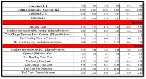
3.4 Creating Database for Cutting Tools
The main formula used in creating database for cutting tools which are total time per part, total cost per part, cost per part for maximum production rate and minimum cost per unit. All the formula with colour is fixed and it will automatically be calculated.
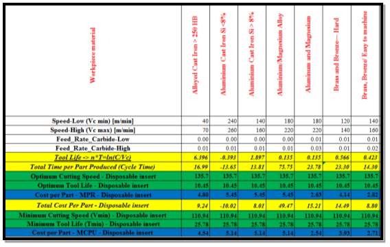
CTMAX=COth+COtm+COtmTMAX+CttmTMAX
CT(MIN)=Cots+Cotm+Cotctm(min)TMIN+cttm(min)TMIN
 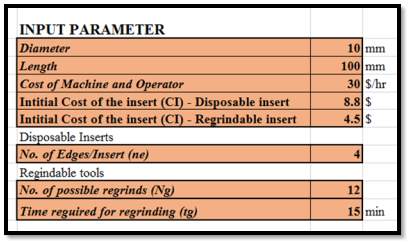 In this part, the value in the input parameter can be change according to the user part design. Then, the formula will use the input to calculate based on basic formula explain in chapter 3.2.1. In this part, the value in the input parameter can be change according to the user part design. Then, the formula will use the input to calculate based on basic formula explain in chapter 3.2.1.
3.5 Integrating Database into Program
3.5.1 Design Modelling
- Figure below show that a turning part which had prepare by using CAD/CAM software. There are operation and tool operation highlighted in the figure. All the cost operations is based on this model.
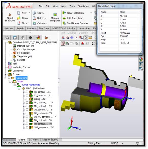
Figure 3‑1: Turning process in SolidWorks Software.
- In SolidCAM when the part is done the designer can use SolidCAM Operations tab to reach Tool Sheet. In here this tab, the user designer has possibility to extract everything with every tool.
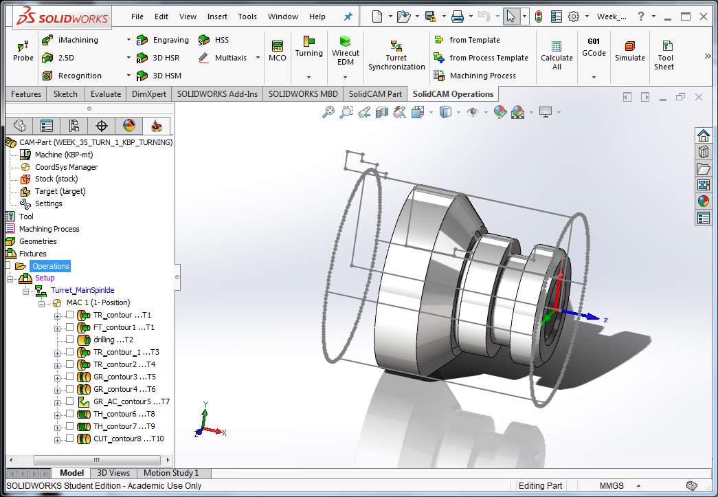
Figure 3‑2: SolidCAM operation
- This will show export dialogue.
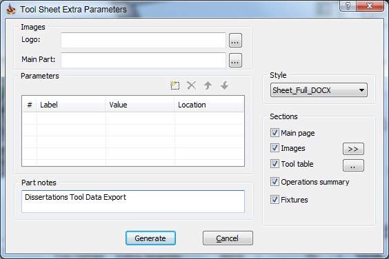
Figure 3‑3: Tool Sheet Extra Parameters
3.5.2 Program Data
The data shown below is pick from in file WEEK_35_TURN_1_KBP_TURNING.NC which is generated by CAM (SolidCAM) NC part-program. The function this coding for used for cutting the modelling part created in the CAD/CAM (SolidWorks..).
| ……
T0202
G1998 S1
G#148 G18 G97 G99 S900 M3
M8
mac_number in tmatrix:1
(—————-)
(DRILLING – DRILL)
(—————-)
G0 X98 Z2
G0 X0
G83 R0
G83 Z-77 Q0 F0.037 |
G0 X98
mac_number in tmatrix:1
mac_number in change_tool:1
M9
M5
N3
G28 U0 W0
G28 V0
M01
G333
G53 Z#149
…… |
Figure 3‑4: WEEK_35_TURN_1_KBP_TURNING.NC data.
3.5.3 CIMCO Testing
Next, after the coding has been determine, the part program can be tested by using Software for tool-path simulation (CIMCO). This testing needed to be conducted before manufacturing on Fanuc CNC Machine. To extract data for tool (machine time), the same program will be used.
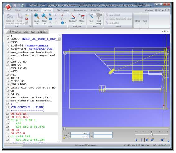
Figure 3‑5: CIMCO Edit Software.
3.5.4 Introduce software
In this part, the presented user of data base and program as shown below has been calculated and will be presented to engineers once it is completed. Further explanation on the detail guides of the software is showed below:
 Open Excel file containing your data base Open Excel file containing your data base 
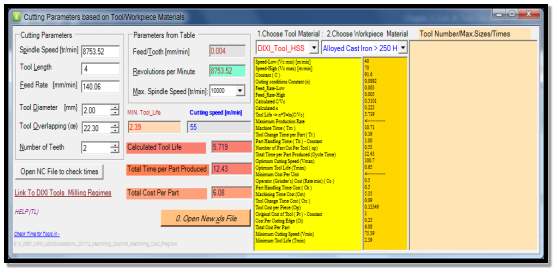
Figure 3‑6: Opening Software.
- Choose the data base file as required as shown in figure below.
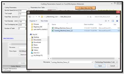
Figure 3‑7: Selecting database
- Monitoring the initial data from database.
 Changing Materials analyse results of calculations done in Database (Excel table…) Changing Materials analyse results of calculations done in Database (Excel table…)
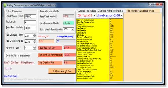
Figure 3‑8: Selecting cutting tool material and workpiece material.
- Open generated NC part-program to extract data
 . To export the data (calculated times for tool life), open CIMCO software and select file (WEEK_35_TURN_1_KBP_TURNING.NC ) by click on the Editor . To export the data (calculated times for tool life), open CIMCO software and select file (WEEK_35_TURN_1_KBP_TURNING.NC ) by click on the Editor  . .
 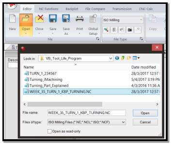
Figure 3‑9: Selecting the NC part-program.
- Then the coding shown below will popup.
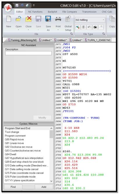
Figure 3‑10: The NC part-program appear in CIMCO.
- Then, click on the Toolpath Statistics
 and the data can be exported by clicking on the Export and the data can be exported by clicking on the Export  . .
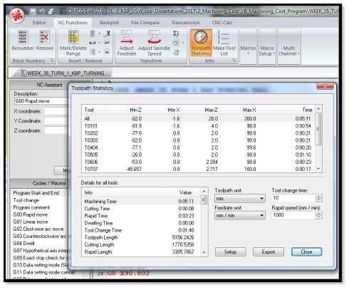
Figure 3‑11: The list of the machine time produce by toolpath statistics for turning process.
- Export it, mark (highlight) and copy into Clipboard.
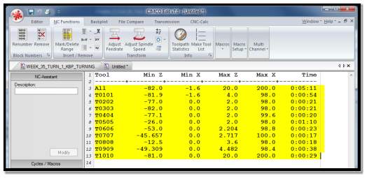
Figure 3‑12: Machine Time.
 Back to the program, click on the Title Back to the program, click on the Title  to import the data from CIMCO and the copied data will appear in the field as shown figure 3-11. to import the data from CIMCO and the copied data will appear in the field as shown figure 3-11.
   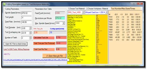
Figure 3‑13: The machine time appeared in right side of the program.
- The blue box is the link to a useful manufacturer website which provided many information about tool parameter that can be used for research.
- Program sets the proper cells in Excel data base to recalculate output values.
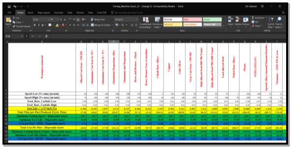
Figure 3‑14: The Excel Database.
4 RESULT AND DISCUSSION
The result is produce form given data (Table 3-1, 3-2 and 3-3). The table below show the overall results for HSS and Carbide cutting tool. The solution of this example is referring in Appendix 1.
Table 4‑1: The result of calculation for HSS and Carbide.
| |
HSS |
Carbide |
| General labour and overhead cost |
$0.396/min |
| Tool cost |
$4.46/edge |
$2.21/edge |
| Cutting speed for minimum cost per part |
35.65 m/min |
65.22 m/min |
| Cost Per Part for Minimum Cost Conditions |
| Tool life |
66 min/edge |
23 min/edge |
| Machine time |
34 min/part |
18.5 min/part |
| Cost per part for MCC |
$20.50/part |
$14.03/part |
| Cutting speed for maximum production rate |
46 m/min |
86 m/min |
| Cost Per Part – Maximum Rate Conditions |
| Tool life |
17.2 min/edge |
8.1 min/edge |
| Machine time |
26.3 min/part |
14 min/part |
| Cost per part for MRC |
$23.57/part |
$15.35/part |
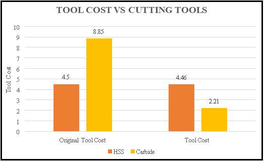
Figure 4‑1: Tool Cost against Cutting Tools
Based on the figure 4-1 presents the comparison between HSS and Carbide tool in terms of tool cost shows that the original tool cost for carbide is more expensive compared to HSS. This is due to the process of manufacture the carbide tool is more complicated than the HSS tool. The difference of original tool cost for both is about 49%. However, when the number of edge of the tool is taken to account, the tool cost for carbide is better than the HSS tool. The variation between two tool cost is approximately 50%. So, the researcher can conclude that based on the tool cost, using Carbide tool is better compared to HSS which means rather than buying the cheapest tool price which only have one cutting edges and required a time to changing and grinding that will affected the machining time of the operation. Therefore, it is better to buy an expensive tool such as insert which have more than one cutting edges and it can be used much longer by exchanging the edges in one operating. In addition, after all the cutting edges is used and dull, the insert can be throw away or recycled.
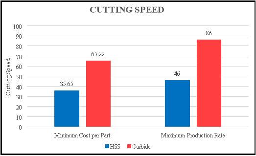
Figure 4‑2: Cutting Speed, meter per minutes.
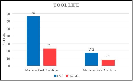
Figure 4‑3: Tool life, minutes per edges.
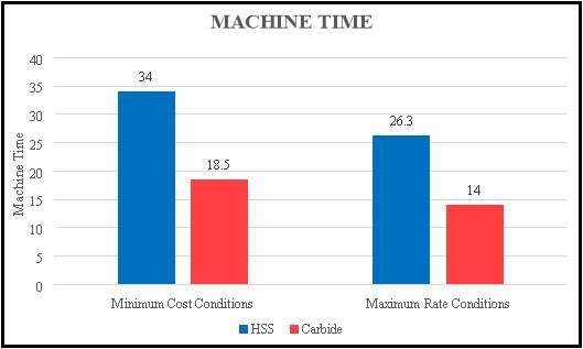
Figure 4‑4: Machine Time, minutes per part.
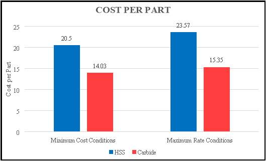
Figure 4‑5: Cost per Part.
The above result shows that Carbide tool performs better results in term of speed and cost per part compared to High speed steel. From Figure 4-3, when the speed is higher, the tool life will be affected which made the life of cutting tool shorter, shown in Figure 4-4. However, the with high speed, the machine time take to produce one part is faster, refer Figure 4-5. Lower speeds allow the tools to last longer, and it is uneconomical to change tools too often if either the cost of tools or the time to change them is high. A vital effect of this tool cost factor is that disposable inserts typically own a significant economic advantage over regrind able tooling. Even though the cost per insert is significant, the number of edges per insert is large enough and the time required to change the cutting edge is lower that disposable tooling normally reaches higher production rates and lower costs per unit product, refers to Figure 4-5.
5 CONCLUSION
5.1 Summary
To minimise cost of cutting tool trials and maximise the applicability to industry is the aim for this project. However, due to the difficulty of field circumstances, to develop a cost model program is a complex task which can simulate the performance requirements for all machining operations. The results are produce based on the sample data given from the books. To show how the software calculated and to give to user clear explanations on usage of formula. Cost is primarily affected by tool life and power consumed, while for the production throughput is mainly affected by accuracy including dimension and surface finish. The factors that can be modified to optimise the process are cutting velocity, feed and depth, work material, tool material, tool shape and cutting fluid.
The developed cost software and user interface allow manufactures to improves their processes with regard to production and costs in terms of cutting tools. Based on practical approach, the model assist with current cost calculations and prediction of impending products. Through identification of cost drives and evaluation of system capabilities, improvement can be made within the scope of available resources. The database used for qualitative computation of cutting tools performance is modular and easily expandable. The data of cutting tools can be added from different resources, including other merchant provided information. The results in terms of cutting tools and cost still need to be verified to be compared with its real performances. So, this software help user to choose and select suitable cutting tools for turning process.
5.2 Future Work
5.2.1 Limitations
Several limitation and difficulties was being faced by the student during completing this research, in terms of time, sources and communication with industrial. The student has to collect data from internet and from database different company because of there are something happen to the Rolls Royce that they were not happy to share their data which is the industrial supervisor for this research. Furthermore, it was hard to deciding the suitable formula will be using in this research. The option that the student has is by going through the website and downloading the related formula. The information required for database was not enough and the resources related to the topics also hard to found. Regarding to time, the student did not have enough time to learn the software in depth due to time constrain. It takes more times to understand the how the software behaves due to lack of knowledge about the software. Because of the limited time and resources also the student able to create the database on lathe or turning operation only.
5.2.2 Recommendations
Recommendations for the future works are as follows:
- Adding various types of cutting tool materials such as ceramics, cement, diamond etc. in the excel database.
- The current software only has one module which is turning with various workpiece materials. Therefore, other operations of machining can be added such as milling, drilling etc. But, the few formula need to be change for several operations. The cutting time for metalworking operation such as milling and tapping.
- Current program is still under development and verification and endorsement can be done to improve it.
REFERENCES
- “Cutting Tool (Machining)”. En.wikipedia.org. N.p., 2016. Web. 5 Mar. 2017.
- “File:ISO1832 Insert Code.Svg – Wikimedia Commons”. Commons.wikimedia.org. N.p., 2017. Web. 11 Feb. 2017.
- Ashish, Bhateja et al. “Optimization of Different Performance Parameters I.E. Surface Roughness, Tool Wear Rate & Material Removal Rate with The Selection of Various Process Parameters Such as Speed Rate, Feed Rate, Specimen Wear, Depth of Cut in CNC Turning Of EN24 Alloy Steel – An Empirical Approach”. The International Journal of Engineering and Science (IJES) 2.1 (2013): 103-113. Print.
- Chang, T., Wysk, R. and Wang, H. (1998). Computer-aided manufacturing. 1st ed. Upper Saddle River, N.J.: Prentice Hall, pp.1-13.
- Die Schneide verdint das Geld, Werkzeuge revie, April 1995.
- Drozda, T. and Wick, C. (1983). Tool and manufacturing engineers handbook. – 1: Machining. 1st ed. Dearborn,Mich.,: Society of Manufacturing Engineers, pp.59-63.
- Elmunafi, Mohamed Handawi Saad, M.Y. Noordin, and D. Kurniawan. “Tool Life of Coated Carbide Cutting Tool When Turning Hardened Stainless Steel Under Minimum Quantity Lubricant Using Castor Oil”. Procedia Manufacturing 2 (2015): 563-567. Web.
- El Wakil, S. (1998). Processes and design for manufacturing. 2nd ed. Boston: PWS Pub. Co., pp.357-358.
- Gane, N., and L.W. Stephens. “The Wear and Fracture Resistance of Ceramic Cutting Tools”. Wear 88.1 (1983): 67-83. Web.
- Ghani, J.A., I.A. Choudhury, and H.H. Masjuki. “Wear Mechanism of Tin Coated Carbide and Uncoated Cermets Tools at High Cutting Speed Applications”. Journal of Materials Processing Technology 153-154 (2004): 1067-1073. Web.
- Gomes de Mattos de Mesquita, Noemia, José Eduardo Ferreira de Oliveira, and Arimatea Quaresma Ferraz. “Life Prediction of Cutting Tool by The Workpiece Cutting Condition”. Advanced Materials Research 223 (2011): 554-563. Web.
- Gu, Jie et al. “Tool Life and Wear Mechanism of Uncoated and Coated Milling Inserts”. Wear 225-229 (1999): 273-284. Web.
- Kennametal.com. (1938). Kennametal | Delivering productivity in the most demanding environments. [online] Available at: https://www.kennametal.com/en/home.html [Accessed 27 Jan. 2017].
- Kompan, Chomsamutr, and Jongprasithporn Somkiat. “Optimization Parameters of Tool Life Model Using The Taguchi Approach And Response Surface Methodology”. IJCSI International Journal of Computer Science 9.1 (2012): 3. Print.
- Kopač, J. “Influence of Cutting Material and Coating on Tool Quality and Tool Life”. Journal of Materials Processing Technology 78.1-3 (1998): 95-103. Web.
- Krar, S. and Check, A. (1997). Technology of machine tools. 5th ed. New York: Glencoe/McGraw-Hill, pp.252-259.
- Lanen, William N et al. Fundamentals Of Cost Accounting. 1st ed. Boston: McGraw-Hill Irwin, 2008. Print.
- M., Narasimha et al. “Improving Cutting Tool Life A Review”. International Journal of Innovation Research in Science, Engineering and Technology 7.1 (2013): 67-75. Print.
- Machining, C. (2016). Introduction to Turning Tools and their Application. [online] www.machiningcloud.com. Available at: https://www.machiningcloud.com/wp-content/uploads/2016/05/MachiningCloud_TurningToolsAndTheirApplication.pdf [Accessed 8 Feb. 2017].
- Maropoulos, P. and Alamin, B. (1996). Integrated tool life prediction and management for an intelligent tool selection system. Journal of Materials Processing Technology, 61(1-2), pp.225-230.
- Morales-Menéndez, Rubén et al. “LOW-COST CUTTING TOOL DIAGNOSIS BASED ON SENSOR-FUSION”. IFAC Proceedings Volumes 40.19 (2007): 141-146. Web.
- Nagaanjeneyulu, K., M. Avinash, and M. Shanmuka Srinivas. “Optimization of Cutting Tool Life Parameters by Applications of Taguchi Method on A CNC Milling Machine”. International Journal of Innovation Research in Science, Engineering and Technology 4.2 (2015): Print.
- Narita, Hirohisa. “A Study of Automatic Determination of Cutting Conditions to Minimize Machining Cost”. Procedia CIRP 7 (2013): 217-221. Web.
- Neugebauer, R. et al. “Resource and Energy Efficiency in Machining Using High-Performance and Hybrid Processes”. Procedia CIRP 1 (2012): 3-16. Web.
- Ranganath, B. J. Metal Cutting And Tool Design. 2nd ed. New Delhi, India: Vikas Publishing House, 1999.,5,45.
- Singal, R. K, Mridul Singal, and Rishi Singal. Fundamentals of Machining and Machine Tools. 1st ed. New Delhi: I K International Publishing House, 2008. Print.
- Stephenson, D. and Agapiou, J. (2006). Metal Cutting Theory and Practice. 1st ed. Boca Raton: CRC Press, Taylor & Francis Group, pp.705-718.
- Team, ME. “Cutting Tool Materials ~ ME Mechanical”. ME Mechanical. N.p., 2016. Web. 16 Feb. 2017.
- Tech.plym.ac.uk. (2009). Cutting Tool Materials. [online] Available at: http://www.tech.plym.ac.uk/sme/mfmt201/cuttingtoolmats.htm [Accessed 16 Mar. 2017].
- Technology, M. (2016). Types of Tool Wear – Flank wear, Crater wear, Corner wear. [online] Mecholic. Available at: http://www.mecholic.com/2016/02/types-of-tool-wear-flank-crater-and-corner-wear.html [Accessed 11 Mar. 2017].
- Tipnis V., A. Cutting Tool Wear. 1st ed. New York: N.p., 1980. Print.
- Trent, E. and Wright, P. (2000). Metal Cutting. 1st ed. Wildwood Avenue, Woburn.: Butterworth-Heinemann.
- Valentino, J. and Goldenberg, J. (2003). Data disk t/a Introduction to computer numerical control (CNC), third edition. 1st ed. Upper Saddle River, NJ: Prentice Hall.
- www.cimco.com. (2014). CIMCO Edit v7 User Guide. [online] Available at: http://www.cimco.com/documents/cimco_edit/user_guides/en/cimco-edit-7-user-guide-en.pdf [Accessed 8 Mar. 2017].
- Lau, W., Venuvinod, P. and Rubenstein, C. (1980). The relation between tool geometry and the Taylor Tool Life Constant. International Journal of Machine Tool Design and Research, 20(1), pp.29-44.
- Lim, S. (1995). The effects of machining conditions on the flank wear of TiN-coated high speed steel tool inserts. Wear, 181-183, pp.901-912.
- Dearnley, P. (1985). Rake and Flank Wear Mechanisms of Coated and Uncoated Cemented Carbides. Journal of Engineering Materials and Technology, 107(1), p.68.
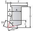
APPENDIX 1 – Tool Table
|
Tool Table For
WEEK_35_TURN_1_KBP_TURNING |
|
1-Turret-1A

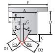
Ext.Rough |
 |
|
A: 25
B: 5
C: 20
D: 50
D1: 3
D2: 3 |
E: 5
F: 15 |
Tool direction:
0 0
Spin Dir.: CW
Ra: 0.8
a: 80
b: 5 |
|
|
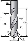
2-Turret-1A

DRILL |
 |
|
D: 28 mm
A: 180
AD: 35 |
TL: 120 mm
OHL: 90 mm
CL: 72 mm
SL: 90 mm
H: 100 mm |
H 2 D 52
Flutes: 1 |
|
|
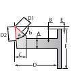
3-Turret-1A

Ext.Rough |
|
|
A: 25
B: 5
C: 20
D: 55
D1: 3
D2: 3 |
E: 5
F: 55 |
Tool direction:
0 0
Spin Dir.: CW
Ra: 0.4
a: 60
b: 5 |
|
|
4-Turret-1A

Int.Rough |
 |
|
A: 10
B: 5
C: 10
D: 100
D1: 4
D2: 5 |
E: 2
F: 30 |
Tool direction:
0 0
Spin Dir.: CW
R: 0.4
a: 60
b: 27 |
|
|
5-Turret-1A

Ext.Groove |
 |
|
A: 25
B: -8
C: 15
D: 40
D1: 7
D2: 7 |
E: -3
F: 15
G: 3 |
Tool direction:
0 0
Spin Dir.: CW
Ra: 0.2
Rb: 0.2
a: -1
b: -1 |
|
|
6-Turret-1A

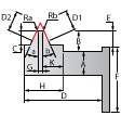
Int.Groove |
 |
|
A: 12
B: 12
C: 7
D: 70
D1: 3
D2: 3 |
E: 11
F: 12
G: 3
H: 3
K: 0 |
Tool direction:
0 0
Spin Dir.: CW
Ra: 0.2
Rb: 0.2
a: -1
b: -1 |
|
|
7-Turret-1A

Ext.Groove |
|
|
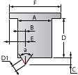
A: 7
B: -3
C: 10
D: 40
D1: 4
D2: 4 |
E: -3
F: 15
G: 2 |
Tool direction:
0 0
Spin Dir.: CW
Ra: 0.2
Rb: 0.2
a: 0
b: 0 |
|
|
8-Turret-1A

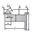
Ext.Thread |
 |
|
A: 25
B: 2.5
C: 4
D: 50
D1: 3 |
E: 6
F: 45 |
Tool direction:
0 0
Spin Dir.: CW
R: 0.1
a: 60 |
|
|
9-Turret-1A

Int.Thread |
 |
|
A: 18
B: 6
C: 4
D: 80
D1: 5 |
E: 6
F: 32
H: 15
K: 8 |
Tool direction:
0 0
Spin Dir.: CW
R: 0.1
a: 60 |
|
|
10-Turret-1A

Ext.Groove |
|
|
A: 15
B: 0
C: 35
D: 60
D1: 3
D2: 3 |
E: 0
F: 15
G: 4 |
Tool direction:
0 0
Spin Dir.: CW
Ra: 0.2
Rb: 0.2
a: 0
b: 0 |
|
|
|
APPENDIX 2 – Operation Summary
|
Friday, May 19, 2017 |
Operation Summary WEEK_35_TURN_1_KBP_TURNING |
|
| # |
Operation Name (Operation type) <Transform> |
| Coordinate system |
Spin Finish |
Feed XY/Feed Normal |
Feed Z/Feed Finish |
Time |
| Tool Number |
Tool Coolant |
| Operation description |
| X Min |
X Max |
Y Min |
Y Max |
Z Min |
Z Max |
|
| 1 |
TR_contour (Turning) |
| MAC 1 (1- Position) |
750.000000 |
0.100000 |
0.050000 |
|
| 1-Turret-1A |
|
|
|
|
|
| 2 |
FT_contour1 (Face) |
| MAC 1 (1- Position) |
1100.000000 |
0.200000 |
0.050000 |
|
| 1-Turret-1A |
|
|
|
|
|
| 3 |
drilling (Drilling) |
| MAC 1 (1- Position) |
900.000000 |
0.036667 |
0.080000 |
|
| 2-Turret-1A |
|
|
|
|
|
| 4 |
TR_contour_1 (Turning) |
| MAC 1 (1- Position) |
1000.000000 |
0.100000 |
0.050000 |
|
| 3-Turret-1A |
|
|
|
|
|
| 5 |
TR_contour2 (Turning) |
| MAC 1 (1- Position) |
1000.000000 |
0.100000 |
0.050000 |
|
| 4-Turret-1A |
|
|
|
|
|
| 6 |
GR_contour3 (Grooving) |
| MAC 1 (1- Position) |
1000.000000 |
0.180000 |
0.120000 |
|
| 5-Turret-1A |
|
|
|
|
|
| 7 |
GR_contour4 (Grooving) |
| MAC 1 (1- Position) |
1000.000000 |
0.150000 |
0.100000 |
|
| 6-Turret-1A |
|
|
|
|
|
| 8 |
GR_AC_contour5 (Angled Grooving) |
| MAC 1 (1- Position) |
1000.000000 |
0.100000 |
0.050000 |
|
| 7-Turret-1A |
|
|
|
|
|
| 9 |
TH_contour6 (Threading) |
| MAC 1 (1- Position) |
600.000000 |
0.100000 |
0.050000 |
|
| 8-Turret-1A |
|
|
|
|
|
| 10 |
TH_contour7 (Threading) |
| MAC 1 (1- Position) |
750.000000 |
0.100000 |
0.050000 |
|
| 9-Turret-1A |
|
|
|
|
|
| 11 |
CUT_contour8 (Cutoff) |
| MAC 1 (1- Position) |
1000.000000 |
0.100000 |
0.050000 |
|
| 10-Turret-1A |
|
|
|
|
|
| Total time: |
0:00:00 |
APPENDIX 3 – Calculation for Cost Model
| GENERAL LABOUR AND OVERHEAD COST
Co=cd+co60
Co=6.75+1760
Co=$0.396/min |
| TOOL COST:
HSS
ct=CI+NgCgtgNg+1
ct=4.50+150.371)(1215+1
ct=$4.46/edge |
TOOL COST:
CARBIDE
ct=CINe
ct=8.854
ct=$2.21/edge |
| TOOL LIFE EQUATIONS FOR HSS:
InV1+nInT1=InV2+nInT2 |
| HSS
In41.4+nIn30=In33.8+nIn90
n=In41.4-In(33.8)In90-In(30)
n=0.188
Since
VTn=C, then
41.4300.188=C
C=78.46
So, tool life equation is
VT0.188=78.46 |
CARBIDE
In60.6+nIn30=In45.1+nIn90
n=In60.6-In(45.1)In90-In(30)
n=0.27
Since
VTn=C, then
60.6300.27=C
C=151.81
So, tool life equation is
VT0.27=151.81 |
| CUTTING SPEED FOR MINIMUM COST PER PART
VMIN=CCoC0tc+Ct1n-1n |
| HSS
VMIN=78.460.3960.3964+4.4610.188-10.188
VMIN=35.65 m/min |
| CARBIDE
VMIN=151.810.3960.3963+2.2110.27-10.27
VMIN=65.22 m/min |
| COST PER PART – MINIMUM COST CONDITION
CTMIN=COth+COtm+COtmTMIN+CttmTMIN
TMIN=CVMIN1n
tm=πDL1000VMINf |
| HSS
TMIN=78.4635.6510.188
TMIN=66 min/edge
tm=π(177.8)(330.2)1000(35.65)(0.152)
tm=34 min/part
CTMIN=0.396(10)+0.396(34)+0.396(4)3466+4.463466
CTMIN=$20.50/part |
CARBIDE
TMIN=151.8165.2210.27
TMIN=23 min/edge
tm=π(177.8)(330.2)1000(65.22)(0.152)
tm=18.5 min/part
CTMIN=0.396(10)+0.396(18.5)+0.396(3)18.523+2.2118.523
CTMIN=$14.03/part |
| CUTTING SPEED FOR MAXIMUM PRODUCTION RATE
VMAX=Ctc1n-1n |
| HSS
VMAX=78.46410.188-10.188
VMAX=46 m/min |
CARBIDE
VMAX=151.81310.27-10.27
VMAX=86 m/min |
| COST PER PART – MAXIMUM RATE CONDITIONS
CTMAX=COth+COtm+COtmTMAX+CttmTMAX
TMAX=CVMAX1n
tm=πDL1000VMINf |
| HSS
TMAX=78.464610.188
TMAX=17.2 min/edge
tm=π(177.8)(330.2)10046)(0.152)
tm=26.3 min/part
CTMAX=0.396(10)+0.396(26.3)+0.396(4)26.317.2+4.4626.317.2
CTMAX=$23.57/part |
CARBIDE
TMAX=151.818610.27
TMAX=8.1 min/edge
tm=π(177.8)(330.2)1000(86)(0.152)
tm=14 min/part
CTMAX=0.396(10)+0.39614)+0.396(3)148.1+2.21148.1
CTMAX=$15.35/part |
APPENDIX 4 – Installation guide for CIMCO Edit V7
|


