DC Micro-grid for Lighting in a Commercial Application
Info: 16563 words (66 pages) Dissertation
Published: 17th Dec 2019
Tagged: Electronics
Abstract
This project explores the current use and potential future, of a lighting based direct current (DC) micro-grid system in the context of commercial applications. This will be effectuated through qualitative methods of data collection and modelling analysis techniques pertaining to the operational characteristics of the system. The field of lighting based DC micro-grids is a relatively newcomer to the landscape of rigorous research. However, a quantity of literature has been accumulated on comparable subjects and a robust research framework have been proposed.
For present purposes, a case study method will be employed. Based on a typical Light-Emitting Diode (LED) lighting scheme, an in-depth analysis will catalogue the level of remunerative available from deriving the power source from a neutral DC micro-grid arrangement opposed to a conventional alternating current (AC) network. These will be modelled and analysed on a Co-operative food store located in the rural community of Conon Bridge. The main hypothesis proposes that through the elimination of the repeated diminishing AC-DC conversion process, this paper will provide a compendium of the characteristic benefits, barriers and energy-saving potential of a LED based lighting distribution network in its raw DC form.
Interest in ‘direct current’ is motivated by a combination of the following factors: the rapid expansion in the current and anticipated future use of energy efficient products that utilise DC power internally; the continued emergence of DC appliances and electrical accessories designed for direct grid-connected applications in the residential and commercial sector; a 20 strong industrial nation led consortium focused on tackling the world’s climate change crisis through the introduction of DC generated renewable energy sources and the energy saving currently being demonstrated through direct-DC commercial data centres and similar applications.
For such technology to be considered as common practice in the commercial service sector, more investment and organisational commitment is required to discover the real potential of such configuration and act as a catapult towards a self-sustaining infrastructure.
Keywords: DC Micro-grid, LED lighting, energy-efficient, innovation
Contents Page
Abstract
Acknowledgements
List of tables
List of figures
Abbreviations
1. Introduction
1.1 Direct Current
1.2 LED Lighting
1.3 Sustainable Energy Future
1.4 DC Micro-grid
1.5 LED Based DC Micro-grid Lighting System
2. Conon Bridge Co-operation Superstore
2.1 Conon Bridge Co-operation Store Lighting Design
2.2 Philips Lighting 4MX900 LED Module Analysis
3. Conon Bridge DC Micro-grid
3.1 Operational Characteristics Comparison
4. DC Network Considerations
4.1 The Interruption of Direct Current
4.2 Earthing Typology of a DC Network
4.3 Choice of Protective Device
4.4 Additional Methods for Protection
5. System Infrastructure Design
5.1 AC System
5.2 DC System
5.3 System Infrastructure Comparison
6. System Comparison
7. Conclusion
References
Bibliography
Appendix 1
Technical Design Drawings
Co-Operative Proposed Fixture Layout
Philips Proposed Lighting Layout
Appendix 2
Manufacturer Literature
Figure 16 Philips Lighting 4MX900 LED Luminaire
Figure 17 Philips Lighting Xitanium/Fortimo LED Drivers Indoor
Figure 18 GE Compact Power Line CP3500 rectifier Model: J2014003
Appendix 3
Design Calculations
Figure 19 Relux Light Planning Software Calculation
Trimble MEP ProDesign Calculation
Figure 20 AC System Cable Calculation
Figure 21 DC System Cable Calculation
Appendix 4
Component Cost Enquiries
Figure 22 Philips Lighting 4MX900 LED Luminaire Enquiry
Figure 23 GE Compact Power Line CP3500 rectifier Model: J2014003 Enquiry
Cable Wiring
Figure 24 AC System Cable Enquiry
Figure 25 DC System Cable Enquiry
End
List of tables
Table 1 Philips Lighting Xitanium/Fortimo LED Driver characteristics
Table 2 Shop Floor Lighting AC Power Consumption
Table 3 Conon Bridge Opening Hours (Co-op Food store finder – back to being Co-op, 2017)
Table 4 Shop Floor Lighting Running Cost Analysis (Conventional AC System)
Table 5 Shop Floor Lighting DC Power Consumption
Table 6 Shop Floor Lighting Running Cost Analysis (DC Micro-grid System)
Table 7 Operational Characteristics Comparison
Table 8 BE EN 60445:2010 Cable marking criteria
Table 11 Lighting circuit cable schedule (supplied from AC voltage source)
Table 12 AC Lighting System Equipment Schedule
Table 13 Lighting circuit cable schedule (supplied from DC voltage source)
Table 14 AC Lighting System Equipment Schedule
Table 15 System Infrastructure Cost Comparison
Table 16 Overall System Cost Comparison
List of figures
Figure 1 Typical AC and DC voltage waveform
Figure 3 Typical arrangement of a LED semiconductor
Figure 4 Photovoltaic panel and lead acid battery (Solar, 2016)
Figure 5 Conon Bridge Co-operative store development site highlighted – Google Maps extract
Figure 6 Conon Bridge Co-Operative Superstore
Figure 7 Co-Operative Store Lighting Arrangement
Figure 8 Philips 4MX900 LED module Figure 9 Philips Lighting Xitanium/Fortimo LED Driver
Figure 10 Typical AC & DC system component arrangement
Figure 11 GE Compact Power Line CP3500 rectifier (model: J2014003) characteristics
Figure 12 Short-circuit test carried out by ABB SACE (courtesy of ABB, 2007)
Figure 13 Fault typologies in a network insulated from earth
Figure 14 AC Lighting load distribution
Figure 15 DC Lighting load distribution
Figure 16 Philips Lighting 4MX900 LED Luminaire
Figure 17 Philips Lighting Xitanium/Fortimo LED Drivers Indoor
Figure 18 GE Compact Power Line CP3500 rectifier Model: J2014003
Figure 19 Relux Light Planning Software Calculation
Figure 20 AC System Cable Calculation
Figure 21 DC System Cable Calculation
Figure 22 Philips Lighting 4MX900 LED Luminaire Enquiry
Figure 23 GE Compact Power Line CP3500 rectifier Model: J2014003 Enquiry
Figure 24 AC System Cable Enquiry
Figure 25 DC System Cable Enquiry
Abbreviations
| AC | Alternating Current |
| AFFL | Above finished floor level |
| AlGaAs | Aluminium-gallium-arsenide |
| BRE | Building Research Establishment |
| BREEAM | Building Research Establishment Environmental Assessment Method |
| BS | British Standard |
| CIBSE | Chartered Institution of Building Services Engineers |
| DALI | Digital Addressable Lighting Interface |
| DC | Direct Current |
| EIA | Energy Information Administration |
| EN | European norm |
| ESSs | Energy storage systems |
| EU | European Union |
| GBA | Gross building area |
| GSA | Gross sales area |
| IK | The international numeric classification for the degrees of protection provided by enclosures for electrical equipment against external mechanical impacts |
| IP | Ingress Protection – The international numeric classification defining levels of sealing effectiveness of electrical enclosures against intrusion from foreign bodies and moisture. |
| LED | Light-emitting diode |
| LG | Lighting guide |
| Lux | The SI unit of illuminance, equal to one lumen per square meter |
| Nb-Ti | Niobium-titanium |
| Nb3Sn | Niobium-tin |
| O&M | operation and maintenance |
| P | Active power |
| PV | Photovoltaic |
| Ra | Rendering Index Average |
| RES | Renewable energy sources |
| U.S. | United States |
| V | Voltage |
| VLED | Visible light-emitting diodes |
1. Introduction
There is no plea that will justify the use of high-tension and alternating currents in either in a scientific or a commercial sense. They are employed solely to reduce investment in copper wire and real estate (Edison, 1889).
There is a long-standing debate as to whether the modern day economy would have been better off if Nikola Tesla had prevailed over Thomas Edison in the ‘War of Currents’ in the late 1880s. At the heart of the argument, Nikola Tesla and Thomas Edison were embroiled in a battle over the practicality of alternating current (AC) against Direct Current (DC) to fulfil society’s hunger for electrical power. With electricity supplies in their infancy, much depended on choosing the right technology to advance and develop into today’s electrical infrastructure that is responsible for supplying 17.7 Terawatts of power globally to meet the world’s energy demands (International – U.S. Energy Information Administration (EIA), 2017).
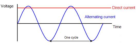
Figure 1 Typical AC and DC voltage waveform
Electrical current in general is the flow of charged particles, or specifically in the case of AC and DC current, the flow of electrons. Alternating current can be describe simply as the movement of an electrical charge through a medium in the form of a conductor or semiconductor that changes direction periodically. This in contrast, direct current is the unidirectional flow of charge and is considered constant over a given time period. There is many long-standing debates surrounding the use of AC over DC throughout a multitude of applications, however during the height of America’s industrial revolution, the desire for efficiency was key in playing the deciding factor of the victor. By 1887, Thomas Edison had constructed 121 DC producing power stations in the United States whilst Tesla, on the other hand, had filed for seven U.S. patents in the fields of polyphase AC motors and power transmission. A turning point in the battle came when George Westinghouse, a famous industrialist from Pittsburgh, purchased Nikola Tesla’s patents for AC motors and transmission as he believed this could be the missing link in long-distance power transmission to complement his contribution towards his passion, transportation. With the key advantage of alternating current being with the simplicity involved in transforming to higher levels, this superiority helped combat against the issues experienced when transporting over long distance with reduced line losses. Through this, there appeared to be no contest with its inferior counterpart, direct current.
These characteristic strengths were conveyed during the 1893 World’s Fair (Novak, 2013) when George Westinghouse successfully bid to electrify the fair utilising Tesla’s alternating current invention undercutting their competitor, General Electric, who were the promoters of Edison’s direct current generation technology. This was further demonstrated later that year with Westinghouse being awarded the contract to generate power from the Niagara Falls auspiciously promoting Tesla’s polyphase AC induction motor and illuminating the State of Buffalo on November 1896 (Belfield, 1976) obliterating Edison’s hope of advancing in his quest of being crowned the pioneer of electricity as its currently known today.
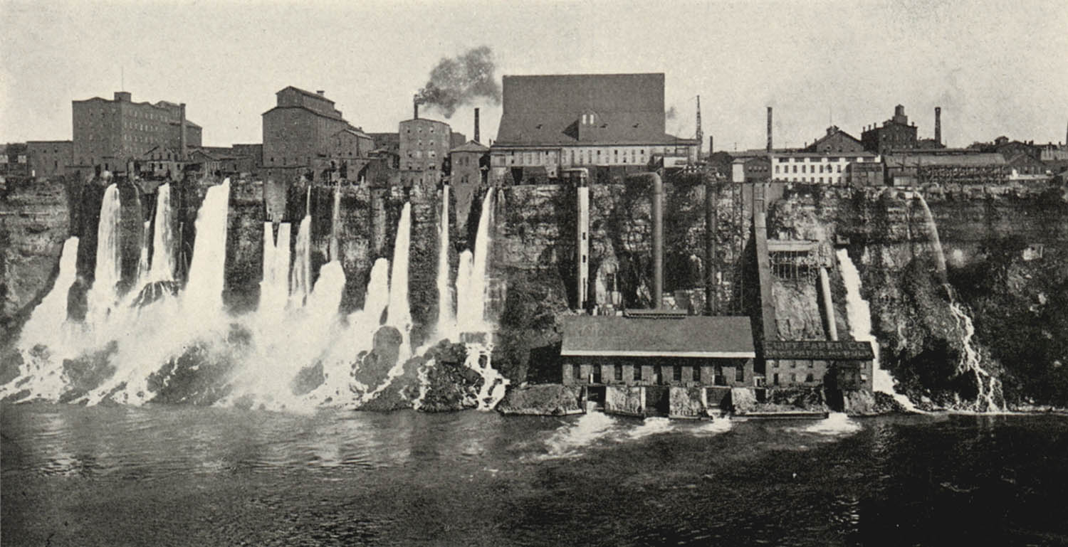
Photo credit: n/a. Source: The Niagara Falls Electrical Handbook: Being a Guide for Visitors from Abroad Attending the International Electrical Congress, St. Louis, September 1904. Niagara Falls, N. Y.: Publicised under the auspices of the American Institute of Electrical Engineers, 1904. p. 36.
Figure 2 General View of Power Development by the Niagara Falls Hydraulic Power and Manufacturing Company.
The latter part of the 19th century saw the first footsteps in a technological revolution that would dwarf all discoveries made in electrification up to that point. Whilst the modern day electricity based infrastructure is taken for granted today by society, those early advances in electrification profoundly changed every aspect of human life ranging from existing historical technologies in the form of lighting, refrigeration and air conditioning to pathing the way for present-day ground breaking discoveries in medicine, science and technology. It would appear that alternating current had all but eradicated any practical use of direct current, however in recent years, direct current has seen a renewed renaissance. Today our electricity is still predominantly powered via alternating current generation but with an ever-changing energy climate and through continued advances in technology, direct current appears to be prevailing as the preferred option for the modern day electronic based industry/equipment.
1.1 Direct Current
In the early years of power generation, the alternating voltage from a single coil was commutated to convert AC to DC. Commutation essentially means reversing the negative polarity of the AC voltage so that the voltage produced does not alternately change its sign and the current delivered by the generator flows in one direction. The fundamental principles of electricity state that, while the resistive power losses grows as the square of the current, the amount of power transferred is proportional to the product of the current and voltage. DC was condemned fruitless due to the limitations in its transformation.
With transformers representing one of the oldest and most mature elements in a power transmission and distribution network, a generation ago DC transformers were regarded as a fundamental component and considered to be fictional until a superconducting version appeared in the 1960 (I. Giaever, 1966). Ivar Giaever discovered that it was possible to make a novel DC transformer by using a superconductor such as Nb-Ti and Nb3Sn to drag vortices through one another. Throughout various technical literature, DC transformers are commonly referenced with DC converters as synonymous due to their method of internal switching to produce an AC waveform that is capable of being stepped up or down by the principle of electromagnetic induction, and switched back to a new DC voltage level. Yet this nomenclature is relatively new. Through this advance in technology, direct current’s potential use throughout a diverse spectrum of applications were discovered and resulted in a fundamental change to the electrical industry infrastructure posing many questions within engineering design, economics and safety standards.
Today, the fact is that many domestic loads, such as consumer electronics, telecommunications, electric vehicles and LED lighting all run on DC power internally. For decades, DC appliances have been present in niche markets offering proof of their capability of serving all major electrical industries end-users. Electronic appliances were initially introduced into society to help with daily tasks, and through continuous development, have become an indispensable part of our daily lives. However, as DC appliances they tend to be higher priced than their mainstream AC counterparts, the fundamental designs are applicable to commonality use and have led to a proliferation of power supplies that are capable of converting a standard mains AC voltage to range of low-voltage DC voltages. With the potential of large energy savings when switching AC appliances to DC-compatible appliances, even if they are initially running on AC, the percentage of the internal consumption of DC loads for residential and commercial is growing exponentially. Through various studies, it is perceived that these savings could be enhanced by a direct-DC power system that would eliminate the AC-to-DC conversions losses which constitute on average 14% of the overall AC load losses (Garbesi, Vossos and Shen, 2011). As a result, the electronic appliance business is continuously growing with many brand companies introducing high-energy efficient products, which operate on a DC voltage, into consumer market such as the assiduously growing business of LED lighting.
1.2 The History of Lighting
Until a little over a century ago, artificial lighting was based on the emission of radiation brought about by the burning of fossil fuels, animal and vegetable oils, waxes and fats with a wick to control the rate of burning (MacIsaac, Kanner and Anderson, 1999). The next major development was the introduction of light produced through the burning of natural gas and coal gas along with the discovery that the higher the temperature of the substance being burned, the greater the light output and whiter the colour that could be achieved. This realisation led to the invention of the incandescent electric lamp in the 1870s by Thomas Edison followed shortly by two commercial discharge lamps, one, invented by D. McFarlan Moore, using carbon-dioxide or nitrogen filled tubes and a second, by Peter Cooper Hewitt, who’s method consisted of passing an electric current through mercury vapour in 1938 (Americanhistory.si.edu, 2017).
1.3 LED Lighting
1962 marked the year of the first red luminescence diode made of a compound semiconductor and from this; the first light-emitting diode in the visible wavelength was born. The founder of this landmark discovery, Nick Holonynak, wrote on receipt of his revelation:
“The latest dramatic laser discoveries may someday make the electric light obsolete. If these plans work out, the lamp of the future may be a speck of metal the size of a pencil-point which will be practically indestructible, will never burn out, and will convert at least ten times as much current into to light as does today’s bulb.” (GE Lighting, n.d.).
The lamp of the future of course is what is commonly now known as the lighting-emitting diode, or LED. At the time of his invention, Holonyak’s diode emitted only red light, but as a result of his divination, it lit a research boom whose multi-coloured offspring are now responsible for illuminating homes and cities all across the world.
A diode is the simplest sort of semiconductor device. Broadly speaking, a semiconductor is a material with a varying ability to conduct electrical current. Most semiconductors are created through the addition of impurities through poor conducting materials. In the case of LEDs, the conductor material is typically aluminium-gallium-arsenide (AlGaAs). In pure aluminium-gallium-arsenide, all of the atoms bond perfectly to their neighbours, leaving no free electrons (negatively charged particles) to conduct electrical current. In an impure material, additional atoms change the balance by either adding free electrons or creating a void to allow free electrons to be transferred. Through either of these alterations, the material is made more conductive.
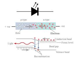
Figure 3 Typical arrangement of a LED semiconductor
As electrons move, a form of energy is released which is commonly known as light. This in turn is due to the energy being released from the atoms that consist of small particles known as photons, the basic unit for light. As free electrons move across a diode and fall into an empty hole in the P-type layer, this movement releases energy causing the emission of light. Dependant on the size of the gap between the conduction bands, this determines the frequency of the photon – in other words, it determines the colour of the light. Visible light-emitting diodes (VLEDs) are materials generally characterised by a wider gap between the conductor band and the electron orbitals.
Among the many artificial light sources available on today’s market, LEDs are deemed as one of the most competitive. The use of LEDs for low-level lighting has been well known for more than a decade and has been gaining popularity in many different applications such as commercial lighting and traffic signals through rapidly evolving technology. In reality, light emitting diodes are the real unsung heroes in the electronics world through their ability to undertake a wide spectrum of tasks ranging from the indication light on an appliance, to the transmitting of information from a remote control and when combined to form an array, capable of being instrumented as traffic light signals or even jumbo television screens. This increased interest in LEDs has challenged engineers throughout the industry to come up with efficient and cost effective solutions to improve on existing designs and research into new technologies as the requirement for energy efficient lighting is growing by a daily demand.
Lighting is an application that is responsible for a huge percentage of energy consumption all over the world. Across the globe, there over 33 billion light sources working daily. This represents 2,650 TWh of electrical energy consumed per year and collates to approximately 20 % of the total global electricity generated (Sabonnadière, 2009). Although many of the lighting installations are deemed as obsolete as there remains a number of factors that promote inefficiencies within the system. Many sources illuminating us still belong to the types of halogen and incandescent lamp, whose energy efficiencies for a given light level in this day in comparison are extremely poor compared to LED. Accordingly, it creates a potential for extensive energy savings. Although the phenomenon of luminescence has been known for a long time, even today the intrinsic problems remain. LED technology offers a promising vision, though is yet to be perfectly mastered. This exploitation is possible by improving on the current lighting technologies that exist today but it is imperative to have a more comprehensive view of the problem at hand to maximise results on working towards a sustainable energy future.
1.4 Sustainable Energy Future
Although fossil fuels are expected to continue supplying much of the energy used worldwide, the capacity of renewable energy sources has increased rapidly in recent years becoming the world’s fastest growing energy market. Recent assessments indicate that the technical potential of renewable energy sources, i.e. the large variety of viable renewable energy solutions that have been developed to date, are theoretically capable of substituting fossil-fuel-based technologies for all sectors of the energy-system. With this is mind, and with the introduction of an industry wide renewable energy generation network, it has been calculated that when operated at full capacity, renewable energy sources are capable of producing substantially more energy than the current global demand (Edenhofer et al., 2013). The European Union (EU) strategic aims clearly describe the role of distributed generation and Renewable Energy Sources (RES) in electricity generation (Karabiber et al., 2013). The integration of existing network grids with renewable energy sources have the potential for infinite use by the end users whilst addressing the current concerns over the rate of consumption of fossil fuels and the inherited side effect of carbon dioxide emissions contributing to the warming of the Earth’s atmosphere through the natural greenhouse effect.
However, electricity generated from renewable sources can rarely provide an immediate response to energy demand as they fail to deliver a continuous supply that can be easily manipulated to satisfy the current consumption needs. At present, the production of electricity is highly centralised and often a long distance away from its end-users. Load demand is generally based on the prediction of daily and seasonal trends, but also, when production is not sufficient, on the contribution of supplementary energy sources such as reservoirs in the form of natural gas combustion and water pumping. Delocalised electricity production and the introduction of variable, fluctuating sources (such a renewable energy technologies) increase the difficulty of stabilizing the power network mainly due to a supply–demand load imbalance. Thus, the requirement for a form of energy storage has been deduced – generally through the use of lead batteries.
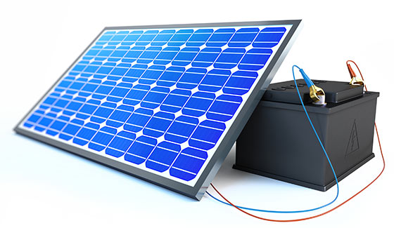
Figure 4 Photovoltaic panel and lead acid battery (Solar, 2016)
On the contrary, lead batteries cannot withstand high cycling rates, nor can they store large amounts of energy in a small volume (Ibrahim, Ilinca and Perron, 2008). Through a burgeoning electricity grid and with the centralised production of electricity, this has led to the development of a complex system of energy production and transmission that makes little use of energy storage. Historically, in an energy context, conversion methods for the ‘storage of electrical current’ were highly unreliable, extremely costly or simply not considered at the outset of a system. This, along with the fact that electricity is mass-produced, transmitted and consumed in an AC format, has created the phenomena that electricity cannot be stored. In this modern of age of technology and high-performance, inexpensive power electronics capable of handling very large power levels have changed all that. It can now be asserted that electricity is capable of being stored throughout all applications, even if it is only by indirect storage. With types of storage technologies being regularly developed, tested and implemented, the use energy storage systems (ESSs) allow for the shifting of the peak demand, the flattening of the consumption pattern and releasing of energy back into the grid during peak hours when it is more valuable. As a result, this has led to the emergence of storage as a crucial element in the management of renewable sources at a cost of further investment and higher operating costs.
Building a cost-effective energy-sustainable future is the aim of many countries, agencies, and research institutes. In the residential and commercial sector, much effort has been directed towards the development of a sustainable, practical building, commonly known as a zero-energy building. The philosophy behind this building is a combination of modern day architecture combined with state of the art energy management technologies that focus on creating a self-sustaining structure capable of becoming independent from the grid whilst satisfying the criteria of a modern day building’s expectations. The electrical system of such buildings can be understood as a subset of the AC smart-grid system and is commonly referred to by many authors as a micro-grid. With the modern day consumer leaning towards an electronic appliance based lifestyle and through an introduction of locally sourced power generation, typically in the form of an array of PV panels and/or small-scale wind turbine, the presence of DC voltage becomes a commonality factor that results in a zero-energy building favouring the philosophy of a DC based grid system. From this, the concept of DC micro-grids was been born.
1.5 DC Micro-grid
Power systems having undergone radicaldevelopment in recent years with significant modifications to the structure, management and operation of distribution networks. Wide spread DC characteristic loads along with a high penetration of renewable embedded generation have required profound changes to the conventional AC grid system. However, a transformation phase is required to move from the conventional AC power system to a smarter, more efficient, innovative DC micro-grid arrangement. Although the current AC grid system is a rigid architecture constructed around the centralised fossil fuels and nuclear power plants, it is becoming increasingly more apparent that it is the result of a bottleneck for expanding the share of renewables. Most promising renewable energy sources like wind and solar are geographically distributed and are often dependant on weather or environmental conditions through hourly changing regional weather and irradiation conditions (Paska, Biczel and Kłos, 2009). Sharing the renewable energy of domestic distributed generators in micro-grids can considerably reduce energy demands on the grid, and thus, provide more efficient energy distribution and lower energy prices.
Local DC distribution systems or DC micro-grids for residential and commercial buildings were not popular until recent times but have become more attractive through their ability to increase a network’s power quality whilst reducing emissions, power losses and network congestions thus potentially improving the overall economics of the system. Micro-grids are promising solutions for integrating large amounts of micro-generation due to their ability to reducing the negative impact of disturbances onto the utility network experienced as a result of the production/consumption of reactive power. In general terms, micro-grids can be defined as a structure that combines distributed generation (DG), ESSs and localised typical consumer loads. While their architecture may vary greatly depending on the type and number of building blocks as well as the application context, a clear distinction can be drawn between AC and DC based micro-grids.
Utilising a low-voltage DC voltage for micro-grid applications provides various advantages over the conventional AC network arrangement. Factors such as a simplified integration process with renewable sources and energy storage systems (battery banks) promote a reduction in the energy-conversion processes and assist with the synchronisation of supply and load demand profiles resulting in overall harmonised energy-efficient network. With renewable sources like solar PV and fuel cells being DC in nature, through the use of commercially available third party interface components, these sources can be directly coupled to a DC bus thereby avoiding the power losses experienced through detrimental DC-AC conversion that currently exists. This is also relevant for the commonly found variable-speed wind generators that undergo an AC-DC-AC conversion before they can be interfaced with the grid. Again, with a DC distribution network, this is the preferred arrangement as it necessitates only a single conversion stage (AC-DC). Since the fundamental principles of DC differ from AC, synchronization complexities, reactive power problems, and power factor correction circuits in appliances can be avoided. It can be concluded that even though AC micro-grids are now predominant, the number of DC micro-grids is expected to increase in the coming years, as they will soon be the right candidates for future energy saving systems.
1.6 LED Based DC Micro-grid Lighting System
In any building environment, there exists plenty of opportunity to attain energy saving as lighting accounts for the second largest primary energy consumption in buildings annually (Arik et al., 2010). With continuous advances in the development and mass production of LEDs, the possibility of replacing conventional light sources with more efficient modern day luminaires has been realised. However, LED lighting is an inherently DC electrical load whereas the traditional electrical infrastructure installed within buildings is distributed in an AC form. Several studies have been undertaken to compare the typical fluorescent lamp and electronic ballast arrangement whilst proposing a driving technique that is capable of driving LEDs without the requirement to replace or modify the existing circuitry. Even so, this is not a viable solution, as an extra power converter is needed to convert the AC power from the conventional AC grid to constant direct current required to power the LED luminaire. To overcome this drawback of the several power losses incurred by the use of an AC-DC power converter to condition the use of electrical power for LEDs, a low voltage DC grid can be applied.
2. Conon Bridge Co-operation Superstore Case Study
In this section, the performance of the proposed DC LED lighting system is presented and discussed in a practical environment. This section covers a case study conducted on the merits of a DC Micro-grid LED lighting system against a conventional AC LED lighting system. The results obtained shall be critically analysed and a comparison undertaken of the two systems.
The case study is modelled on a Co-operative food store located in the Ross-shire village of Conon Bridge and was opened in February 2017. The chosen store was part of Co-op Estate’s tactical franchise roll out which consisted of investment of over £10m in 20 new stores throughout Scotland aimed at benefiting local communities as part of the strategy to refocus their store estate on a convenience whilst expanding the companies’ portfolio.
“Our business is doing really well in Scotland. We’ve increased sales by nearly 10% year-on-year and have also opened more stores in Scotland than any other food retailers.” – Abstract from Co-op news release interviewing Co-operative senior acquisitions manager, Des Malone.
Located in the heart of Dingwall, the new store’s location immediate surroundings consists of a combination of residential properties and a local Primary School with leisure facilities and playing fields.
Details of the chosen Co-operative Food store are as per below –
Site name – Co-operative Food
Address – School Road
Town – Conon Bridge
County – Dingwall
Postcode – IV7 8AF
Country – Scotland
Grid reference – NH 54681 55331
Eastings – 254681 Northings – 855331
Latitude – 57.564619 Longitude – -4.4309657

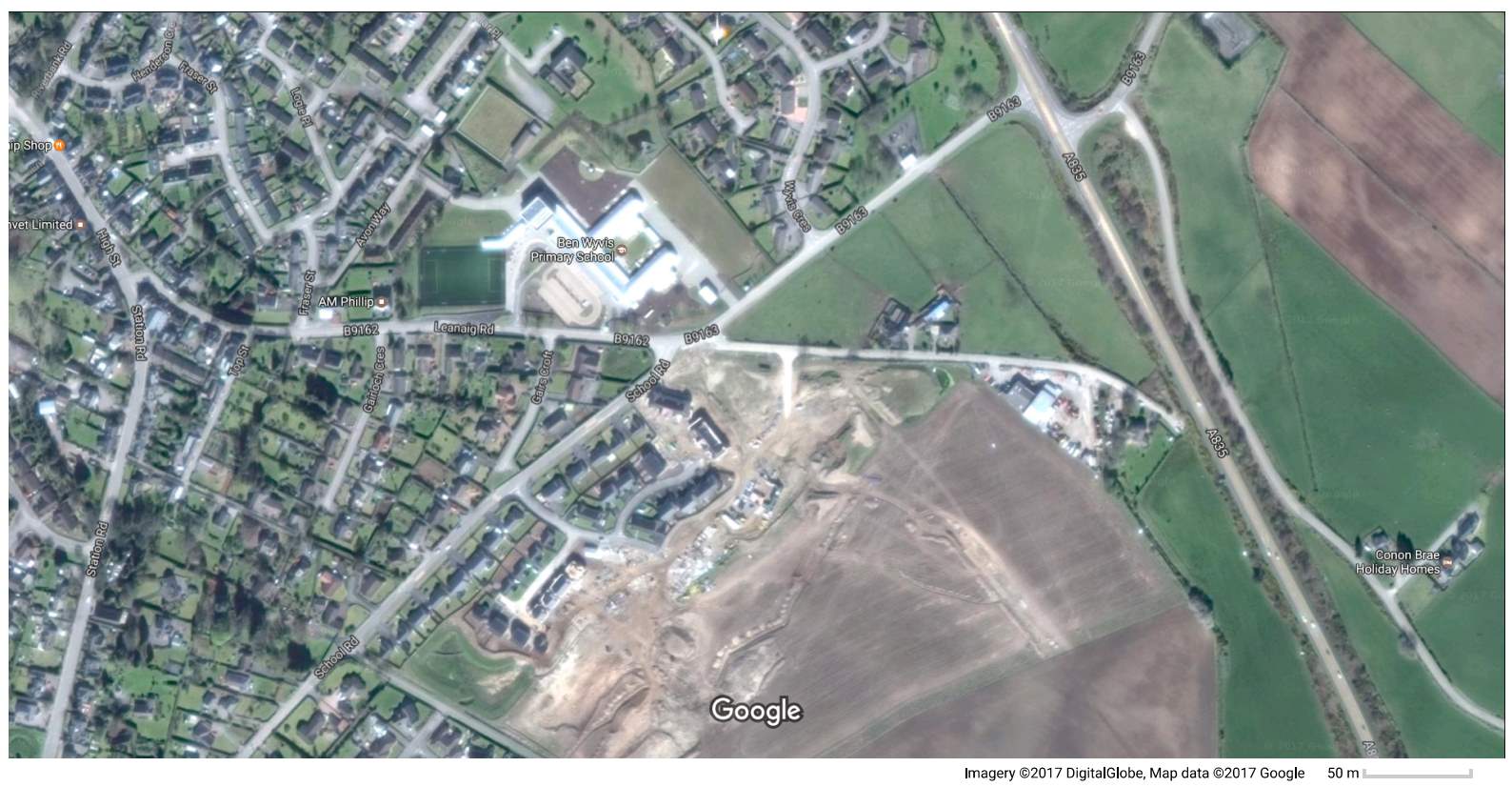
Figure 5 Conon Bridge Co-operative store development site highlighted – Google Maps extract
The chosen store was selected on the basis that it represents a typical commercial property capable of accommodating a DC micro-grid, either as a part of the initial installation works or through a retrofit scheme introduced at a later date. The background focus being on the reduction of the store’s carbon footprint whilst presenting a reasonable payback period through the inherited cost savings.
The store’s construction consists of a steel frame with a combination of metal infill panels and breezeblock. The south facing façade, and also the store’s main entrance, is complimented with an array of glazing. The overall store consists of a Gross Building Area (GBA) of 425 square metres in which the Gross Sales Area (GSA) contributes 280 square metres of that finished in a grey ceramic tiled floor finish. The shop floor area is accessed via a single leaf sliding automatic door dedicated for customer use and a single leaf staff door located to rear of the store accessed from the back of house area. The shop floor boasts an array of Eden/Radfords products that provides three tier shelving, ambient produce units and full height canopied cases with integral feature lighting included. To the east of the shop floor is the sales areas that is made up of 3No.staffed Kesslers basket till machine and two self-service till machines. The store is further attributed by a range of ancillary items such as a Lotto Dream Station, Community Notice Board and wall mounted display screen that contributes to the image of a typical commercial superstore.
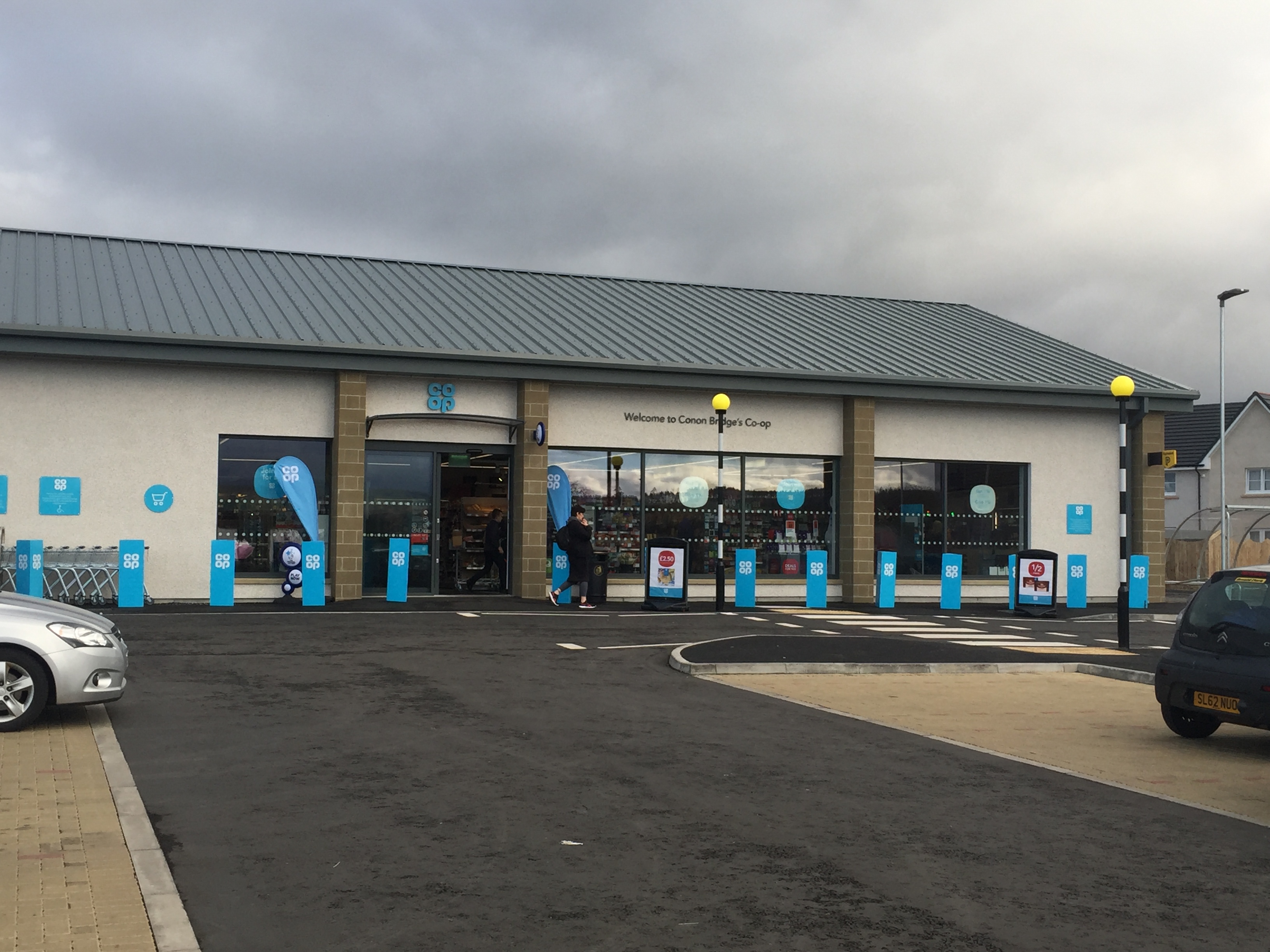
Figure 6 Conon Bridge Co-Operative Superstore
Contained within the Appendix is the technical design drawing produced by the Co-Operative as part of the design process detailing the overall layout of the store.
2.1 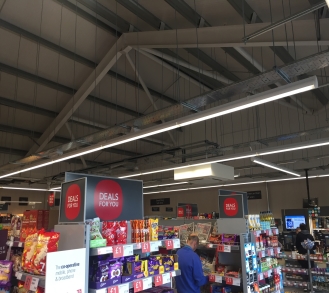 Conon Bridge Co-operation Store Lighting Design
The lighting design element of the store utilises Philips Lighting who were appointed by Dickie & Moore Limited (the Principal Contractor). The proposal was based on providing an energy efficient lighting scheme for all areas of the new store whilst incorporating LED luminaires throughout. The lighting design for the front of house area consists of 57No. Philips 4MX900 – Generation 3 – LED linear modules suspended at a height of 3m above the finished floor level and 13No. three circuit track mounted Philips Lighting StyLid Fresh Food projectors mounted at 2.5m above finished floor level and 300mm away from the associated gondola.
Figure 7 Co-Operative Store Lighting Arrangement
The lighting design was derived from requirements of the The Co-Operative Real Estate’s Model Store Specification Document (NBS) that specifies the following standards and publications that must be adhered to as part of the design process –
- BS EN 12464-1 2011 Lighting of Work Places – Part 1 – Indoor Work Places
- BS EN 15193:2007 Energy performance of buildings. Energy requirements for lighting
- Building Regulations Approved Document L2A: Conservation of fuel and power in new buildings other than dwellings
- Building Research Establishment (BRE) Digest 498: Selecting lighting controls
- BREEAM Non-domestic Buildings – Technical Manual: Version: SD5073 – Issue:3.0
- CIBSE Code for Lighting 2009
- CIBSE LG01 Lighting Guide 01: The Industrial Environment – LG1
- CIBSE LG03 Lighting Guide 03: The Visual Environment for Display Screen Use – LG3
Through a correlation of the above standards, the desired lux level for the front of house area is 750 lux average at a working plane of 1000mm AFFL and to the vertical shelving facades with a minimum colour rendering (Ra) of 80 and limiting glare rating of 22.
With reference to the lighting design proposal produced by Philips Lighting, this arrangement was replicated with the use of industry standard approved Relux Light Planning Software for the purpose of this case study. Relux Light Planning Software is a simulation software that allows for the interpretation of a given light source, contained within the confines of a set area, to determine to the lighting (lux) level achieved at a specified reference plane by a mathematical calculation process. The lighting levels achieved within the front of store area at a reference plane of 1 metre above the finished floor level is 1340 lux. The results are contained within the Appendix. Project lighting designers were contacted during the research phase of this case study; however, no official lighting design calculations were obtained. In addition, due to contractual elements of the project, the Operation and Maintenance (O&M) manual was under review by the Co-operative Service Engineer Representative in which the commissioned lux level surveys results were unattainable.
For the purpose of this case study, it is assumed that the lighting proposal technical design drawing contained within the Appendix was accepted and installed as suggested.
This case study shall focus solely on the main aisle lighting within front of house area open to the general public which employs the Philips Lighting 4MX900 luminaire. The main purpose of this exercise was to obtain a typical load demand of the shop floor lighting for analysis within this case study.
2.2 Philips Lighting 4MX900 LED Module Analysis
The Philips Lighting 4MX900 LED module represents that of a typical linear LED luminaire used in commercial retail environments and similar applications. The luminaire is constructed of aluminium housing with clear polymethyl methacrylate diffuser providing an ingress protection (IP) factor of IP40 (wire protected) and mechanical impact protection (IK) factor of IK02. Contained within the luminaire housing is a Philip Lighting Xitanium PSD (power supply unit with DALI interface) LED driver which operates on an AC electrical supply voltage of 220-240V and at a frequency of 50-60Hz. The driver is capable of producing a DC output voltage with a stepped range of 20-80V and an output current with a range of 200-700mA. The luminaire consumes an initial input power of 49W with an inrush current of 22A over a time period of 0.275ms. Through this configuration, the 4MX900 produces 6000lm with an efficiency of 122lm/W. The manufacturer’s literature is contained within the Appendix.
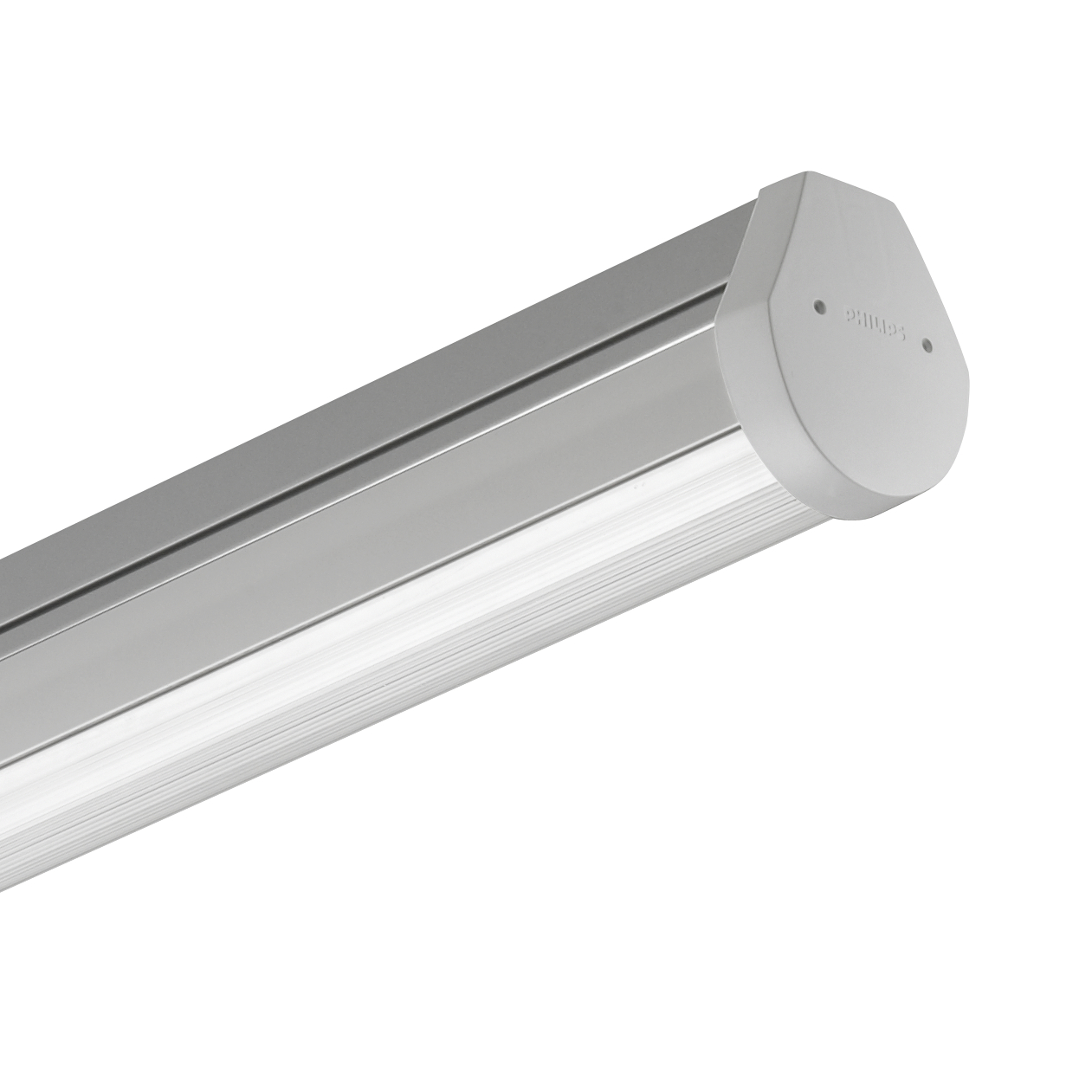
Figure 8 Philips 4MX900 LED module Figure 9 Philips Lighting Xitanium/Fortimo LED Driver
The Philips Lighting 4MX900 LED module utilises the Philips Lighting Xitanium/Fortimo LED Driver, with a specified efficiency range between 80-90%. Utilising this value, in Table 1 below is an analysis of the electrical characteristics and power consumption of the luminaire when operated by the LED driver based on the manufacturer’s literature.
Table 1 Philips Lighting Xitanium/Fortimo LED Driver characteristics
| Philips Lighting Xitanium/Fortimo LED Driver | ||
| Input characteristics | ||
| Input voltage (Vac) | Input current (mA) | Input power (W) |
| 230 | 213 | 49 |
| Conversion characteristics | ||
| Efficiency (%) | ||
| 80* | ||
| Output characteristics | ||
| Output voltage (V) | Output current (mA) | Output power (W) |
| 20 – 80 | 200 – 700 | 39.2 |
*Due to the running current of luminaire operating within the upper threshold under normal conditions, it is assumed that the conversion efficiency is within the lower region of the quoted value.
Based on this information obtained in Table 1 it is apparent that through the AC-DC conversion of the LED driver, a total of 9.8W is lost per driver. Considering this, Table 2 indicates the total power loss inherited throughout the store as a result of this process.
Table 2 Shop Floor Lighting AC Power Consumption
| Shop Floor Lighting Power Consumption (Conventional AC System) | |
| Total No. of luminaires | |
| 57 | |
| Power consumption | |
| Total initial input power (P) | 2793W |
| Total power consumed (by Lighting) (P) | 2234.4W |
| Total power lost through AC-DC conversion (P) | 558.6W |
From above, it can be concluded that the store losses on average 558.6W of active power through the shop floor LED lighting system alone. Considering this, the calculated value was then compared against the opening hours of the store and the average cost electricity (standard rate) (pence/kWh). Listed in Table 3 is the opening hours of the store obtained from the company website including an additional two hours above the stated opening hours to allow for staff activities such as stocktaking, cleaning etc.
Table 3 Conon Bridge Opening Hours (Co-op Food store finder – back to being Co-op, 2017)
| Conon Bridge Opening Hours | ||
| Day | Opening | Closing |
| Monday – Saturday | 07:00 | 10:00 |
| Sunday | 09:00 | 10:00 |
| Weekly Total (hours) | 117* | |
*Includes additional two hours per day
The standard rate for electricity is influenced by various factors such as geographical area and the economies’ current climate. This has an impact on the price through the demand within a given region and the accessibility in which an energy provider can contribute to National Grid through the existing infrastructure. With fuel prices continuously changing, a figure of £00.14 (pence/kWh) was applied for this case study based on the publications and findings of the Energy Savings Trust which were last reviewed and published in March 2017 (Home and us, 2017).
Calculated in Table 4 is the running costs based on a combination of the calculated energy demand of the lighting system, the operating hours of the store and the electricity cost.
Table 4 Shop Floor Lighting Running Cost Analysis (Conventional AC System)
| Shop Floor Lighting Running Cost Analysis | ||
| Costing | Weekly | Annual |
| Theoretical running cost | £36.60 | £1,903.20 |
| Actual running cost | £45.75 | £2379.00 |
| Cost difference | £9.15 | £475.80 |
The above calculations do not take into account any specific agreed tariffs or standing charges but still can be considered a reliable reflection of the average running costs of the store. Assuming that Conon Bridge is a typical representation of the 20 new Co-op stores being rolled out across the country, with the Philips luminaire being installed throughout, it can be assumed with the use of a simple mathematical calculation the combined AC-DC conversion loss cost of £9,516.00 is occurred per annum. These costs are acquired solely as a result of the conversion process required to convert the AC source supply voltage into a low-voltage DC voltage required to operate the luminaires.
3. Conon Bridge DC Micro-grid
The validation of the proposed DC micro-grid makes use of the current LED Luminaire arrangement serving the front of house area of the Co-operative store with minor alterations required to the existing electrical infrastructure or indeed integration into any proposed future distribution system. Indicated in Figure 10, is a simplistic system schematic is provided which details the existing component configuration of a typical AC lighting distribution network against the proposed DC powered micro-grid system.
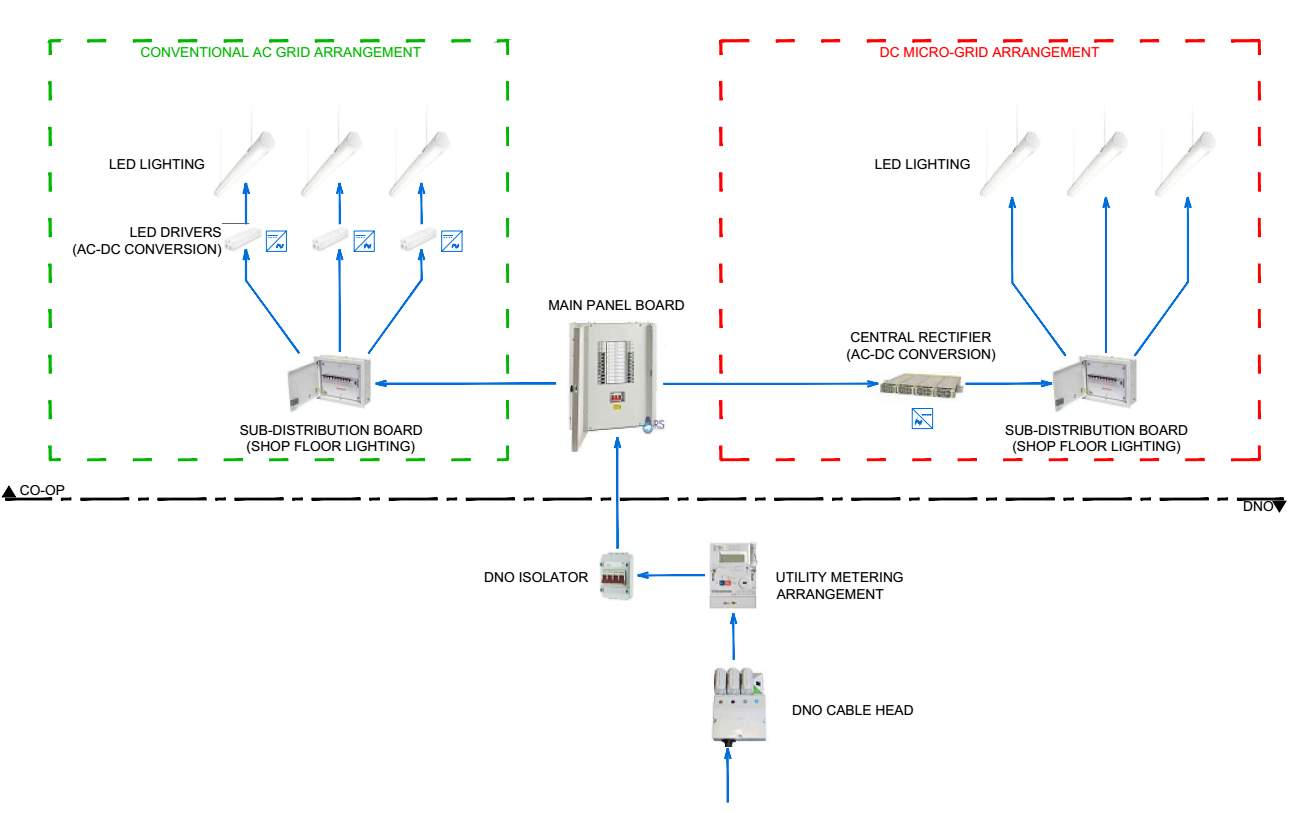
The proposed DC micro-grid system distribution closely resembles that of the AC conventional system with the exception of a single central rectifier unit opposed to the individual local LED drivers contained within the luminaire’s housing. The central rectifier will interface the AC supply voltage with the DC lighting load through an AC-DC conversion process in line with the luminaire’s operational voltage requirements. For the purpose of this study, the GE Compact Power Line CP3500 Rectifier (model: J2014003) will be utilised based on its suitability towards the given application and its commercial availability. Similar to the Philips Lighting Xitanium/Fortimo LED Drivers, the GE Compact Power Line Rectifier will undertake the same voltage conversion process through a more efficient technique whilst eliminating the accumulative power conversion losses as calculated in the previous section. With the lighting load demand operating at 2,234.4W, the CP3500 model is also suitable as it is capable of supplying a maximum rated out power of power of 3500W – sufficiently more than what is required including the typical industry standard allowance of 20% for future system expansion and alterations.
The proposed unit also boasts various features such as a DC output voltage of 48V that falls within the voltage category of Band I as specified by the International Standard IEC standard voltages Edition 6.2, 2002, literature which applies to any nominal voltage conforming below 750Vdc and BS 7671:2008+A3:2015 Requirements for Electrical Installations. IET Wiring Regulations, 2008, where protection against electric shock is provided under certain conditions due to the value of the voltage. This in turn results in two benefiting factors – the risk of electric shock is reduced significantly in comparison to the 230Vac system when supplying the same load current and the luminaire no longer requires a protective conductor in the form of a dedicated connection to earth due to its Class I IEC protection certification. A Class I category stipulates that only the housing of the luminaire requires to be earthed due to a combination of exposed metallic parts and the presence of a ‘dangerous’ operating voltage but as this is now reduced to 48Vdc it can be discounted.
Simulating the same operating conditions as assumed for the conventional AC system arrangement, the same principles were applied to the DC micro-grid system to determine the typical running costs.
Figure 11 GE Compact Power Line CP3500 rectifier (model: J2014003) characteristics
| GE Compact Power Line CP3500 rectifier (model: J2014003) | ||
| Input characteristics | ||
| Input voltage (Vac) | Input current (A) | Input power (W) |
| 230 | 10.02 | 2,303.51 |
| Conversion characteristics | ||
| Efficiency (%) | ||
| 97 | ||
| Output characteristics | ||
| Output voltage (V) | Output current (mA) | Output power (W) |
| 48 | 46.55 | 2,234.4 |
With the use of a single AC-DC conversion process, it is evident that the lighting system experiences an overall positive reaction through a reduction in the system’s operating load requirements. This is a result of the efficiency of the rectifier operating at 97% as stated within the manufacturer’s guidelines opposed to the initial value of 80-90% of the LED driver. It should be noted that this value is listed as the minimum possible value attainable under normal operating conditions and the theoretical operating value is closer to 0.995%. This in turn would reduce the overall operational load demand by a further 57W but for this purpose of this case study, the worst-case scenario has been assumed to provide an equal and fair comparison of the two systems. In Table 5 provided below is an analysis of the system’s overall efficiency based on the GE Compact Power Line rectifier.
Table 5 Shop Floor Lighting DC Power Consumption
| Shop Floor Lighting Power Consumption (DC Micro-grid System) | |
| Total No. of luminaires | |
| 57 | |
| Power consumption | |
| Total initial input power (P) | 2,303.51W |
| Total power consumed (by Lighting) (P) | 2,234.4W |
| Power lost through AC-DC conversion (P) | 69.11W |
Referring to the information calculated above, it is apparent that through a single AC-DC conversion process the total power loss of the overall system falls by 70W. Based on this value, the systems’ running costs were then calculated against the operational hours of the luminaires utilising the standard rate of electricity of £00.14 (pence/kWh) as described in the previous section.
Table 6 Shop Floor Lighting Running Cost Analysis (DC Micro-grid System)
| Shop Floor Lighting Running Cost Analysis | ||
| Costing | Weekly | Annual |
| Theoretical running cost | £36.60 | £1,903.20 |
| Actual running cost | £37.73 | £1,961.96 |
| Cost difference | £1.13 | £58.76 |
3.1 Operational Characteristics Comparison
Through the information obtained in the previous chapters, it can be concluded that there is significant differences in the overall power consumption and running costs of the AC conventional system in comparison to the DC Micro-grid system. Provided below is a comparison focused solely on the operational characteristics and running costs of the two networks highlighting any potential cost savings achieved by minimising the conversion process.
Table 7 Operational Characteristics Comparison
| Operational Characteristics Comparison | ||
| Reference | AC System | DC Micro-grid |
| Total initial input power (P) | 2,793W | 2,303.51W |
| Total running cost per annum | £2,379.00 | £1,961.96 |
| Power lost through AC-DC conversion (P) | 558.6W
(80% efficiency) |
69.11W
(97% efficiency) |
| Total running cost occurred through AC-DC conversion | £475.80 | £58.76 |
| Reduction in power (AC-DC) (P) | 489.49W | |
As catalogued in the Table 7, by consolidating the conversion process into a single transformation, the overall load demand of the system is reduced by a total of 490W. Assuming this is a constant value in line with the operational hours of the shop floor lighting and true reflectance of the values indicated by manufacturer’s equipment literature, this reduction in power collates to a cost saving of £417.04 per annum. By applying this value across the 20No.stores as part of the new roll out scheme, on the basis that they are a similar representation to that of Conon Bridge, a potential saving of £8340.90 is achievable through the converting of the shop floor lighting system to a DC fed micro-grid system. This cost saving projected over a period of 5 years would in turn present a significant operational cost savings alongside a reduction in the maintenance cost based on the reduction in the number of component parts required to form a complete and operational system.
Although, as the initial cost savings of a DC micro-grid over a conventional AC system appear beneficial, due to the introduction of a DC network, special precautions and design procedures need to be considered to ensure the installation conforms to the applicable industry standards.
4. DC Network Considerations
Among the main considerations for the wider use of DC circuits in buildings is the selection of appropriate switchgear, protective devices and electrical accessories. Knowing the electrical characteristics of direct current and its difference compared with alternating current is fundamental to understanding how to employ direct current as a safe and practical voltage throughout a system. Many of the standards for electrical accessories and protective devices currently common in the industry are relevant to AC systems only, and products complying solely with these standards may not be suitable for DC applications as a result of its unidirectional trend constant over a given time period. This attribute is attained from analysing a ‘pure’ direct current that does not present any fluctuations when quantifying the motion of charge (Q) over a given point. Based on these principles, direct current presents different problems from alternating current in relation to the phenomena associated with the interruption of fault currents since the arc extinction results to be particularly difficult.
4.1 The Interruption of Direct Current
With alternating current, there is a natural passage of current through zero during each half cycle that assists with the quenching of the arc in the event of contacts opening but with direct current, this feature does not exist. As direct current is a constant value in time, to guarantee arc extinction, the current must be forced to pass through zero decreasing it to null. In Figure 12 below is an oscillogram of a short-circuit test detailing the behaviour of the current during the event of contacts opening.
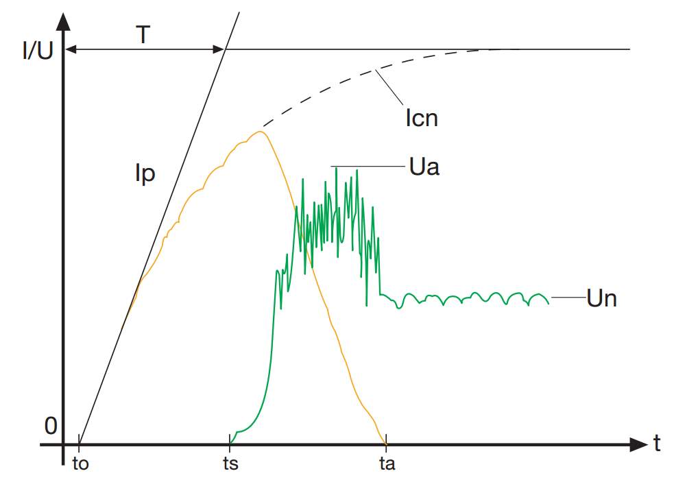
Ip = short-circuit making current
Icn = prospective short-circuit current
Ua = maximum arc voltage
Un = network voltage
T = time constant
To = instant of beginning of short-circuit
Ts = instant of beginning of the circuit breaker contacts
Ta = instant of quenching of the fault current
Figure 12 Short-circuit test carried out by ABB SACE (courtesy of ABB, 2007)
When a short-circuit occurs, the current begins to rise in accordance with the time constant of the circuit. Following the opening of the contacts, the current continues to rise for a short period before decreasing through the resistance that is progressively being introduced into the circuit. As indicated by the graph, the arc voltage remains higher than the supply current of the circuit during the interruption process until the current is completely extinguished. As a result, to obtain gradual extinction, it is necessary to cool and extend the arc to allow for a higher arc resistance to be inserted within the circuit. This is relevant for switchgear and circuit protection implemented in DC systems as they may not be capable of handling and suppressing the arcing occurred when contacts are opened under normal and fault conditions that are not common in AC systems.
4.2 Earthing Typology of a DC Network
To correctly specify the form of protection needed to break a DC short-circuit current, it is necessary to identify the earthing typology of the system to account for any possible fault scenario that may occur. As the Compact Power Line produces 48Vdc, a voltage which falls within Safety Extra Low Voltage (SELV) umbrella of 60Vdc or less, there is no requirement for a protective conductor that results in the network representing that of an Isolated Earth (from the French word Terre) ( I.T.) system. This configuration is the simplest scenario as no connection between the DC power source polarities and earth exist. As a result, only two fault typologies may occur as displayed in the figure below; a fault between two polarities in a short-circuit current by the full supply voltage and a double fault where an initial current may recirculate and find a reclosing path through a second fault.
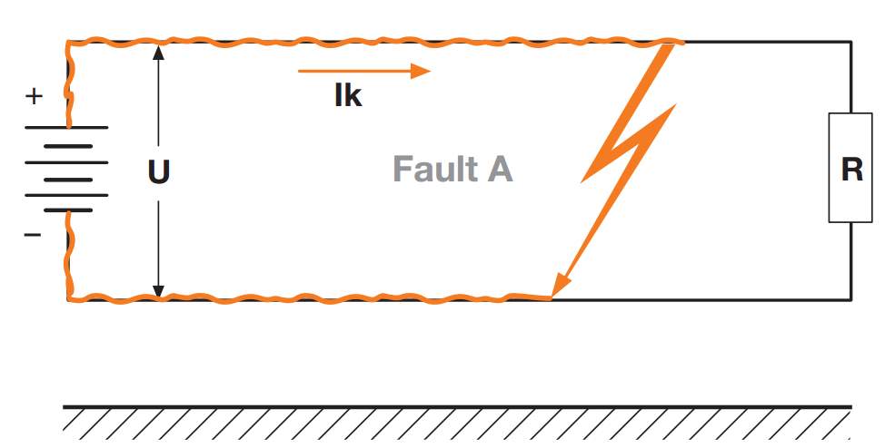
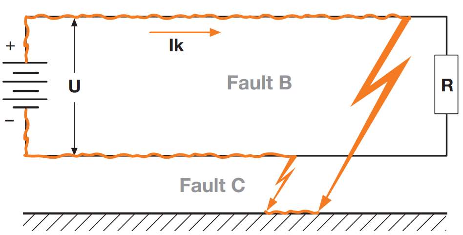
Figure 13 Fault typologies in a network insulated from earth
With this in mind, since no polarities are earthed, this connection arrangement presents the inconvenience of a dangerous overvoltage occurring between an exposed conductive part and earth due to static electricity.
4.3 Choice of Protective Device
Based on this typology, the correct type of protective device for a direct current network can be selected. High breaking-capacity (HBC) fuses and suitably rated high-speed fuses to BS 88 are generally a sound choice. However, in installations such as those of the Co-operation store, it has become common practice to utilise user-friendly resettable devices such as miniature circuit breakers (MCB’s) to minimise disruption and downtime acquired in the event of a fault. In high current ELV applications, faults often lead to overheating and arcing that in turn may result in the protective device failing to operate under certain conditions. As a result, reputable brand manufacturers now provide a full range of DC compatible MCBs suited for a wide range of applications.
At present, residual current devices (RCDs) are not generally available for DC systems although for this scenario they are deemed not required. This is derived from the recent publications of Amendment 3 of the BS 7671:2008:2015 Requirements for Electrical Installations. IET Wiring Regulations, 2008, which states that when cabling is installed within metal studwork walls with no means of mechanical protection provided – RCD protection must be installed. To conform to Amendment 3 and adhere to The Co-Operative Real Estate’s Model Store Specification Document (NBS), 300.030, Steel Surface Trunking – All low voltage power and lighting circuits shall be installed within standard cable trunking in line with BS EN 50085 to provide sufficient means of mechanical protection.
4.4 Additional Methods for Protection
Although Extra-low voltage DC (ELVDC) systems are often a good means of providing protection against electric shock, they are not free from electrical safety hazards and the provisions of the Electricity at Work Regulations 1989 still apply (Kenyon, 2015).
Among these considerations for those designing, installing and maintaining installations of such nature is the requirement for identifying DC circuits separately to AC circuits so that appropriate working practices can be applied. The basic colour-coding scheme harmonized by BS EN 60445, including BS 7671, does not assist installers and maintainers in distinguishing between conductors operating from AC and DC sources, and different voltage bands. One example of this would be a conductor that is identified only by an outer sheath colour of brown may be misconstrued as an AC live conductor (L), opposed to a positive (or negative earth) (L+) of a DC system. A practical approach is to provide a means of identifying the function of each conductor, specifically in installations were single conductors are present, by over-marking cables in the form of alphanumeric marking in addition to colour-coding in line with BS EN 60445:2010 Basic and safety principles for man-machine interface, marking and identification. Identification of equipment terminals, conductor terminations and conductors as indicated within the Table 8.
Table 8 BE EN 60445:2010 Cable marking criteria
| BE EN 60445:2010 Cable Marking Criteria | ||
| Function | Marking | Colour |
| Two-wire unearthed DC power circuit | ||
| Positive of two-wire circuit | L+ | Brown |
| Negative of two-wire circuit | L- | Grey |
| Two-wire earthed DC power circuit | ||
| Positive (of negative earthed) circuit | L+ | Brown |
| Negative (of negative earthed) circuit | M | Blue |
| Positive (of positive earthed) circuit | M | Blue |
| Negative (of positive earthed) circuit | L- | Grey |
| Three-wired DC power circuit | ||
| Outer positive of two-wire circuit derived from three-wire system | L+ | Brown |
| Outer negative of two-wire circuit derived from three-wire system | L- | Grey |
| Positive of three-wire circuit | L+ | Brown |
| Mid-wire of three-wire circuit | M | Blue |
| Negative of three-wire circuit | L- | Grey |
- M identifies either the mid-wire of a three-wire d.c. circuit, or the earthed conductor of a two-wire earthed d.c. circuit.
- Only the middle wire of a three-wire circuit may be earthed.
In instances of multicore circuits, a suitable approach is to install separate voltage bands within dedicated containments to provide a practical indication of which voltage category the circuits fall under and a suitable means of segregation. Although with this in mind, the main concern throughout industry when designing networks of a voltage band less than the typical 230Vac operating voltage is the inherited issue of voltage-drop and the impact this has on the system’s infrastructure. Within the UK, the statutory limits of a 230Vac voltage is ± 10%. This translates to operational parameters of 207V to 253V (The Wiring Regulations, 2008). As the proposed DC micro-grid operates at a much lower voltage value of 48Vdc, the impact this has on the system’s infrastructure is considered below.
5. System Infrastructure Design
5.1 AC System
As the operational characteristics of the luminaire are flexible and capable of operating under a varied range of input parameters as portrayed by the AC system arrangement which consists of integral LED drivers that operate at a voltage range of 20-80V, the system was simulated with a constant DC source supply voltage of 48Vdc based on the output voltage from the GE Compact Power Line. To use as a reference and act as a means of a comparison, the system was simulated under the conventional AC system operational parameters to calculate the required circuit protection ratings and the cross-sectional area of the conductors to satisfy the maximum permissible earth fault loops impedance value for the given application as listed in the Table 9.
Table 9 Maximum earth fault loop impedance (Zs) for Type C circuit-breakers to BS EN 60898 with Uo of 230 V, for operation giving compliance with the 0.4 s disconnection time of Regulation 411.3.2.2 and 5s disconnection time of Regulation 411.3.2.3 (BS7676 Table 41.3)
| Maximum Earth Fault Loop Impedance (Zs) for Type C Circuit Breakers with Uo of 230 V | ||||||||||||
| Rating (amperes) | 6 | 10 | 16 | 20 | 25 | 32 | 40 | 50 | 63 | 80 | 100 | 125 |
| Zs (ohms) | 3.64 | 2.19 | 1.27 | 1.09 | 0.87 | 0.68 | 0.55 | 0.44 | 0.35 | 0.27 | 0.22 | 0.17 |
Where the design current (In) is calculated using the following formula:
In=(230*0.95) (10* In)
(Equation 1)
Also taking into consideration is the maximum permitted voltage drop limits as detailed in the Table 10 –
Table 10 Maximum voltage-drop between the service-connection point and the point of utilization (IEC60364-5-52 table G.52.1)
| Maximum Voltage Drop Limit (LV AC systems) | ||
| Type of installation | Lighting Circuits | Other (heating and power) |
| A low-voltage service connection from a LV public power distribution network | 3% | 5% |
The voltage-drop limits refer to normal steady-state operating conditions and do not apply at the time of simultaneous switching of several loads (fortuitously). With reference to the lighting circuit limitations, a maximum value of 3% of a 230Vac system is permissible which collates to 6.9V.
Taking into account the applicable design parameters, with the use of Trimble MEP ProDesign Calculation software, the cable sizes for the lighting circuits were calculated when supplied from a 230Vac voltage source. As the property benefits from a three phase incoming supply, the lighting load was distributed over the three phase as indicated in the arrangement portrayed in the Figure 14. Through this configuration, a total of 9No. circuits is required to allow for the distribution of the 57No. luminaires evenly across the three phases which calculates to be a total load demand of 1.4A per circuit.
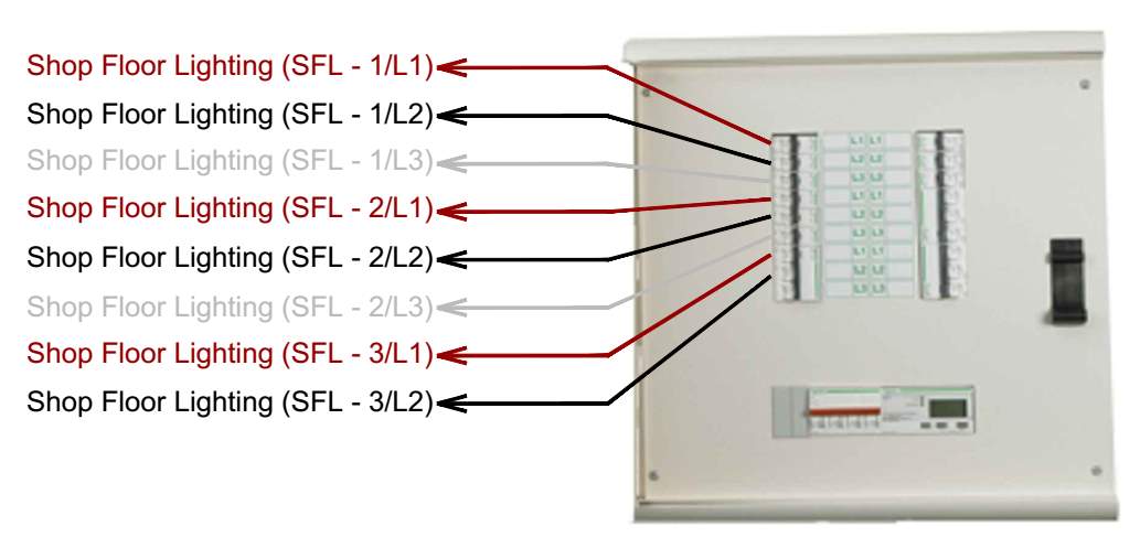
Figure 14 AC Lighting load distribution
From this arrangement, the cable cross sectional area was calculated and the results provided in the Table 11 with a breakdown of the cable calculation analysis included within the Appendix to provide a descriptor of each circuit’s electrical characteristics.
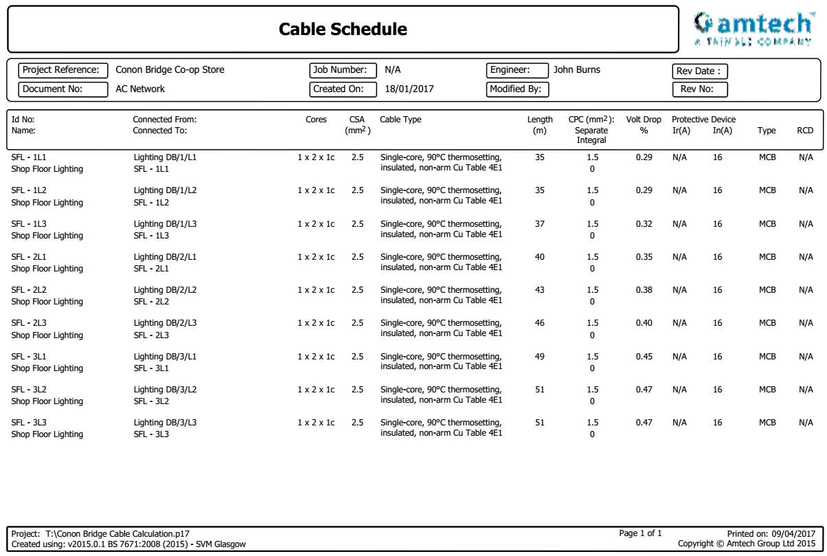
From the results collated in the Table 11, it is apparent that a cross sectional area of 2.5mm2 for the live and neutral conductors and a cross sectional area of 1.5mm2 for the circuit protective conductor satisfies the requirements of volt-drop and permitted maximum values of earth loop impedance. It should be noted that due to inrush current experienced during the initial energisation of the luminaires and through the cumulating of LED drivers, an MCB with a ‘Type C’ was selected to avoid any potential nuisance tripping. This also conforms to the guidance indicated by the manufacturer’s literature that suggests no more than 12No. units are installed on a circuit with protection in the form of a 16A Type C MCB.
Based on this information gathered from the various design calculations, prices for the fundamental components of the system were obtained to determine a budget cost for the installation of the AC system configuration. A pricing schedule is provided in the Table 12 listing the core components.
Table 12 AC Lighting System Equipment Schedule
| AC Lighting System Equipment Schedule | |||||
| Component Ref. | Manufacturer | Catalogue Ref. | Quantity | Price
(inc. VAT) |
|
| Main panel MCCB distribution board | Schneider (or equal and approved) | N/A as component requirement is deemed consistent across both installations | |||
| 6 Way TPN MCB distribution | Schneider (or equal and approved) | SEA9B6* | 1 | £187.99 | |
| 16A Type C MCB | Schneider (or equal and approved) | A9N21555 | 9 | £156.07 | |
| Cable containment | Legrand (or equal and approved) | N/A as component requirement deemed consistent across both installations | |||
| Cable installation | BATT (or equal and approved) | Varied | 1200m | £302.30 | |
| LED luminaire | Philips Lighting | 4MX900 LED60S/840 PSD WB SI L1800 | 57 | £9,781.20 | |
| Total | £10,427.56 | ||||
*Considered a complete entity and includes an integral isolator to BS EN 50947-2
5.2 DC System
Similarly, to the AC system, with the use of Trimble MEP ProDesign Calculation software, the cable sizes for the lighting circuits were calculated when supplied from a DC voltage source. As the GE Compact Power Line is only capable of producing a single-phase output, the luminaires will be derived from a single nominated phase, in this instance Phase L1 (Brown). To provide some form of redundancy, the luminaires were separated over a total of 9No. circuits with each circuit containing 7No. luminaires, similar to that of the AC system wiring arrangement. As the DC system operates on a supply voltage of 48Vdc, the total load demand of each circuit is increased to 5.34A.
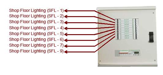
Figure 15 DC Lighting load distribution
From this arrangement, the cable cross sectional area was calculated and the results provided in the Table below with a breakdown of the cable calculation analysis included within the Appendix to provide a descriptor of each circuit’s electrical characteristics.

From the results obtained in the Table 13, it can be concluded that a cross sectional area of 10.0mm2 for the positive and negative conductors are required for circuits with cable lengths up 40m and a cross sectional area of 16.0mm2 for the positive and negative conductors for circuits with cable lengths above the stated 40m. This increase in conductor size is a result of the reduced operating voltage. It should also be noted that due to the system operating on a DC voltage and the array of integral LED drivers being no longer required, the inrush factor applicable for AC installations is removed and the sub-circuit protection is reverted back to a standard ‘Type B’ MCB device. Although, through this arrangement, the inrush factor is transferred to the submains cabling serving the Compact Power Line unit and consideration given to the selecting of the upstream protection device. Based on this information obtained, a pricing schedule is provided in the Table 14 listing the core components of the DC system.
Table 14 AC Lighting System Equipment Schedule
| AC Lighting System Equipment Schedule | |||||
| Component Ref. | Manufacturer | Catalogue Ref. | Quantity | Price
(inc. VAT) |
|
| Main Panel MCCB Distribution Board | Schneider (or equal and approved) | N/A as component requirement deemed consistent across both installations | |||
| Compact power line rectifier | GE | J2014003 | 1 | £4,920.56 | |
| 18 Way SPN MCB Distribution (DC compatible) | Schneider (or equal and approved) | SEA9AN18* | 1 | £143.92 | |
| 16A Type B MCB
(DC compatible) |
Schneider (or equal and approved) | A9N61511 | 9 | £193.21 | |
| Cable Containment | Legrand (or equal and approved) | N/A as component requirement deemed consistent across both installations | |||
| Cable Installation | BATT (or equal and approved) | Varied | 1200m | £1,675.45 | |
| LED luminaire | Philips Lighting | 4MX900 LED60S/840 PSD WB SI L1800 | 57 | £9,781.20 | |
| LED Driver** | Philips Lighting | Xitanium/Fortimo LED Drivers Indoor | 57 | -£1,995.00
+ £230.00 |
|
| Total | £14,949.34 | ||||
*Considered a complete entity and includes an integral isolator to BS EN 50947-2
**Removal of LED driver including bespoke luminaire surcharges results in project cost saving
5.3 System Infrastructure Comparison
Table 15 is a comparison of the two system’s infrastructure costs based on the list prices obtained from various reputable manufacturers. A point of note is that these prices are contestable and may differ from manufacturer to manufacturer but for the purpose of this case study, it is assumed that they represent a typical guide price in today’s current market.
Table 15 System Infrastructure Cost Comparison
| Overall System Infrastructure Cost Comparison | |
| AC System Network Overall Infrastructure Cost | £10,028.78 |
| DC System Network Overall Infrastructure Cost | £14,949.34 |
| Cost Difference | £4,920.56 |
From the information collated in Table 15, although the system component configuration is similar to that of the AC system in terms of structure, due to the GE Compact Power Line rectifier and with an increase in cross sectional area of the conductors, the DC system is considerably more expensive than its counterpart is. Although the GE Compact Power Line is a commercially available product, the increase in cost is expected as a result of the composite of internal electronic components and the functionality of the technology is not common procedure within the lighting industry. It is assumed in years there will be reduction in the list price for such equipment as more options and variants become available in line with the ever-expanding DC appliance and component market.
6. System Comparison
Taking into account the information obtained from operational cost analysis and the circuit design considerations, calculated in Table 16 is an overall cost comparison between the two systems.
Table 16 Overall System Cost Comparison
| Overall System Cost Comparison | ||
| Item | Conventional AC System | DC Micro-grid |
| Infrastructure Cost | £10,028.78 | £14,949.34 |
| Total running cost per annum | £2,379.00 | £1,961.96 |
| Total | £12,407.79 | £16,911.30 |
| Cost Difference | £4,503.51 | |
From Table 16, taking into account the initial setup costs and the associated running costs over a period of 1 year, it is apparent that the DC micro-grid system is significantly more expensive to a tune of £4,503.51. This is as a result of the increased price of core components. Considering this, based on the typical operational hours of the store and based on a standard rate of electricity of £00.14 (pence/kWh), as specified within this earlier section of this study, the end users would expect to see receive a payback over a period of 10 years.
7. Conclusion
This dissertation has described an alternate configuration for the supply of a typical LED lighting scheme within a commercial application through the use of a DC micro-grid network. Presented by a comprehensive literature based on basic electrical principles in line with current industry practices, and incorporating recent technological discoveries and the burgeoning range of applications and uses, the potential benefits are limitations are identified through a bottom up approach. Given the significance of an energy efficient lighting scheme in today’s current global energy climate, a model system analysis was carried out, although at a higher, more abstract level, to provide a comparison against the conventional AC network arrangement in keeping with the nature of typical end user requirements.
The methods put forth here show encouraging results under typical operating conditions and deemed reasonable compared against existing industry expectations. Methods involving lux level calculations, and the sizing of circuit cabling and protection, have been implemented and simulated in terms of their effectiveness at identifying operational differences between the two systems electrical operating characteristics. This paper examines the results obtained in light of industry expectations and assumptions and aims to provide a more definitive cognise elucidation.
A key accomplishment I would claim for the present study is highlighting the simplicity involved in converting from a conventional AC distribution network to a local DC micro-grid system whilst complying with the applicable British Standards.
Although the degree of positive benefits varied, it is acknowledged that changing from an AC source to a directly fed DC source benefits the system considerably. In conclusion, although the initial impact of a DC system results in a higher set up costs, the benefits realised through an operational time period by the reduction in running costs results in a DC fed LED lighting scheme being a sustainable and practical solution for the current market. This a fundamental optimistic picture of future proceedings due to the current rate of technological advances and the accessibility of such equipment. Further benefits may be realised when the principle of a DC micro-grid because a commonality within the industry through manufacturer encouragement.
References
ABB, (2007). ABB circuit-breakers for direct current applications (1SDC007104G0201). Technical Application Papers. ABB, p.13.
Americanhistory.si.edu. (2017). Lighting A Revolution: 20th Century Storeroom. [Online] Available at: http://americanhistory.si.edu/lighting/20thcent/prec20.htm [Accessed 14 Mar. 2017].
Arik, M., Sharma, R., Jackson, J., Prabhakaran, S., Seeley, C., Utturkar, Y., Weaver, S., Kuenzler, G. and Han, B. (2010). Development of a High-Lumen Solid State Down Light Application. IEEE Transactions on Components and Packaging Technologies, 33(4), pp.668-679.
Belfield, R. (1976). The Niagara system: The evolution of an electric power complex at Niagara falls, 1883-1896. Proceedings of the IEEE, 64(9), pp.1344-1350.
Bracale, A., Caramia, P., Carpinelli, G., Mancini, E. and Mottola, F. (2015). Optimal control strategy of a DC micro grid. International Journal of Electrical Power & Energy Systems, 67, pp.25-38.
Co-op Food store finder – back to being Co-op. (2017). Conon Bridge – School Road Co-op, School Road, Dingwall, IV7 8AF. [Online] Available at: https://finder.coop.co.uk/food/store/IV7-8AF/school-road [Accessed 2 Apr. 2017].
Edenhofer, O., Hirth, L., Knopf, B., Pahle, M., Schlömer, S., Schmid, E. and Ueckerdt, F. (2013). On the economics of renewable energy sources. Energy Economics. Germany: Elsevier B.V.
Edison, T. (1889). The Dangers of Electric Lighting. The North American Review, [online] 149, p.690. Available at: https://archive.org/details/jstor-25101896 [Accessed 21 Feb. 2017].
Garbesi, K., Vossos, V. and Shen, H. (2011). Catalogue of DC Appliances and Power Systems. Direct-DC Power Systems Project.
GE Lighting, (n.d.). World’s first LED. [Online] Available at: http://www.gelighting.com/LightingWeb/emea/news-and-media/news/First-LED-by-the-GE-engineer-Nick-Holonyak.jsp [Accessed 14 Mar. 2017].
Home, and us, (2017). Our calculations. [Online] Energy Saving Trust. Available at: http://www.energysavingtrust.org.uk/about-us/our-calculations [Accessed 2 Apr. 2017].
Ibrihaim, H., Ilinica, A. and Perron, J. (2008). Energy storage systems—Characteristics and comparisons. Renewable and Sustainable Energy Reviews, 12(5), pp.1221-1250.
International – U.S. Energy Information Administration (EIA). (2017). [online] Eia.gov. Available at: http://www.eia.gov/beta/international/ [Accessed 21 Feb. 2017].
I. Giaever, “A de transformer,” IEEE Spectrum, pp. 117-122, September 1966.
Kenyon, G. (2015). Technical considerations for D.C. installations. IET Wiring Matters, winter 2015.
MacIsaac, D., Kanner, G. and Anderson, G. (1999). Basic physics of the incandescent lamp (lightbulb). The Physics Teacher, 37(9), pp.520-525.
Novak, M. (2013). [Online] Paleofuture.gizmodo.com. Available at: http://paleofuture.gizmodo.com/where-the-future-came-from-a-trip-through-the-1893-chi-743942247 [Accessed 21 Feb. 2017].
Paska, J., Biczel, P. and Kłos, M. (2009). Hybrid power systems – An effective way of utilising primary energy sources. Renewable Energy, 34(11), pp.2414-2421.
Sabonnadière, J. (2009). Low emission power generation technologies and energy management. 1st ed. London: ISTE Ltd/John Wiley & Sons.
Solar, H. (2016). Hawaii Ends Net Metering and Opens Door for Solar Energy Storage. [Blog] Solar Battery Storage. Available at: http://www.haleakalasolar.com/hawaii-solar/hawaii-ends-net-metering-opens-door-solar-energy-storage/ [Accessed 4 Feb. 2017].
The Wiring Regulations, (2008). IET Wiring Regulations BS 7671:2008 Incorporating Amendment 3:2015. IET.
Bibliography
Balke, J. (2014). Integration of Renewable Energy in Europe. ENER/C1/427-2010(9011-700).
Chiu, H., Lo, Y., Cheng, S., Yan, Y., Lee, H., Wu, K., Lin, C., Ho, S., Tseng, M. and Huang, F. (2010). A single-stage LED lamp driver with low DC bus voltage for general lighting applications. International Journal of Circuit Theory and Applications, 39(11), pp.1161-1175.
Cook, P. (2014). Harmonised Colours and Alphanumeric Marking. IET Wiring Matters, Spring, p.1.
International Electrotechnical Commission, (n.d.). Electrical Energy Storage. Geneva: International Electrotechnical Commission.
Lee, Y., Choi, S. and Mohamed, S. (2015). Advanced Efficiency of DC-LED Lighting Systems to Replace the Conventional AC-LED Lighting Systems. International Information Institute (Tokyo), 18(6(A), p.2437.
Parks, M. (2017). Tesla, Edison and the War of Currents. [online] Eu.mouser.com. Available at: http://eu.mouser.com/applications/tesla-edison-war-of-currents/ [Accessed 21 Feb. 2017].
PBS: Tesla – Master of Lightning: War of the Currents. (n.d.). [online] Pbs.org. Available at: http://www.pbs.org/tesla/ll/ll_warcur.html [Accessed 21 Feb. 2017].
The Wiring Regulations, (2008). IET Wiring Regulations BS 7671:2008 Incorporating Amendment 3:2015. IET.
Whittingham, M. (2012). History, Evolution, and Future Status of Energy Storage. Proceedings of the IEEE, 100(Special Centennial Issue), pp.1518-1534.
World Scientific, (2002). DC Transformers and DC Josephson (-like) Effects in Quantum Hall Bilayers. New Haven: World Scientific.
Youngquist, R., Ihlefeld, C. and Starr, S. (n.d.). A DC Transformer. Florida: Kennedy Space Center, NASA.
Zhong, W. and Haigh, J. (2013). The greenhouse effect and carbon dioxide. Weather, 68(4), pp.100-105.
Appendix 1
Technical Design Drawings
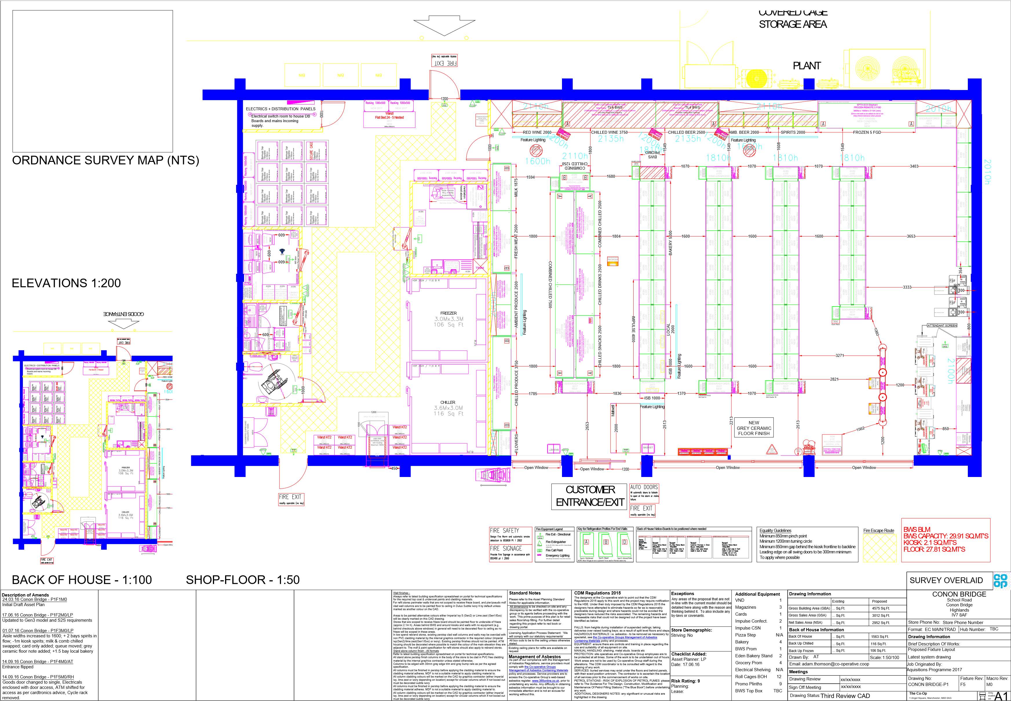
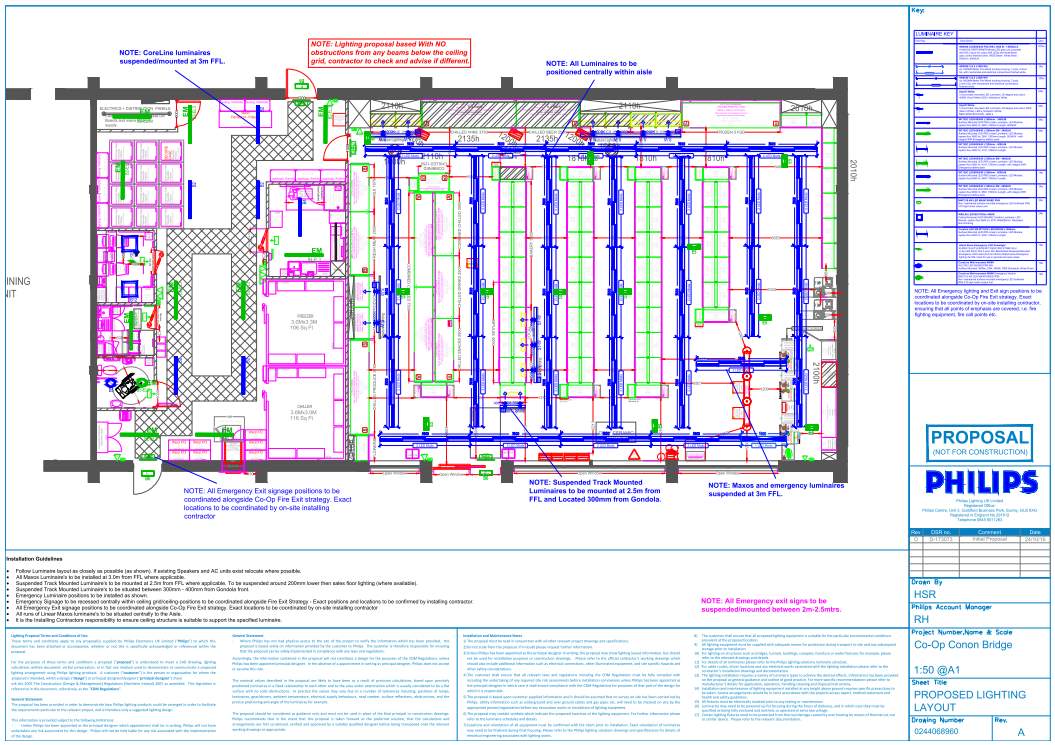
Appendix 2
Manufacturer Literature
Figure 16 Philips Lighting 4MX900 LED Luminaire
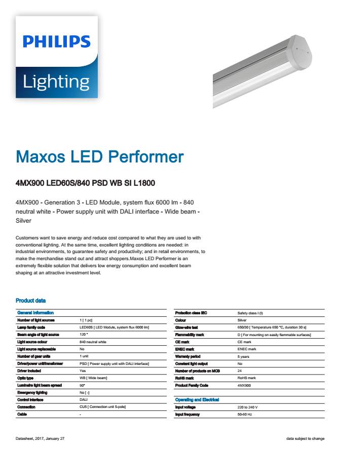
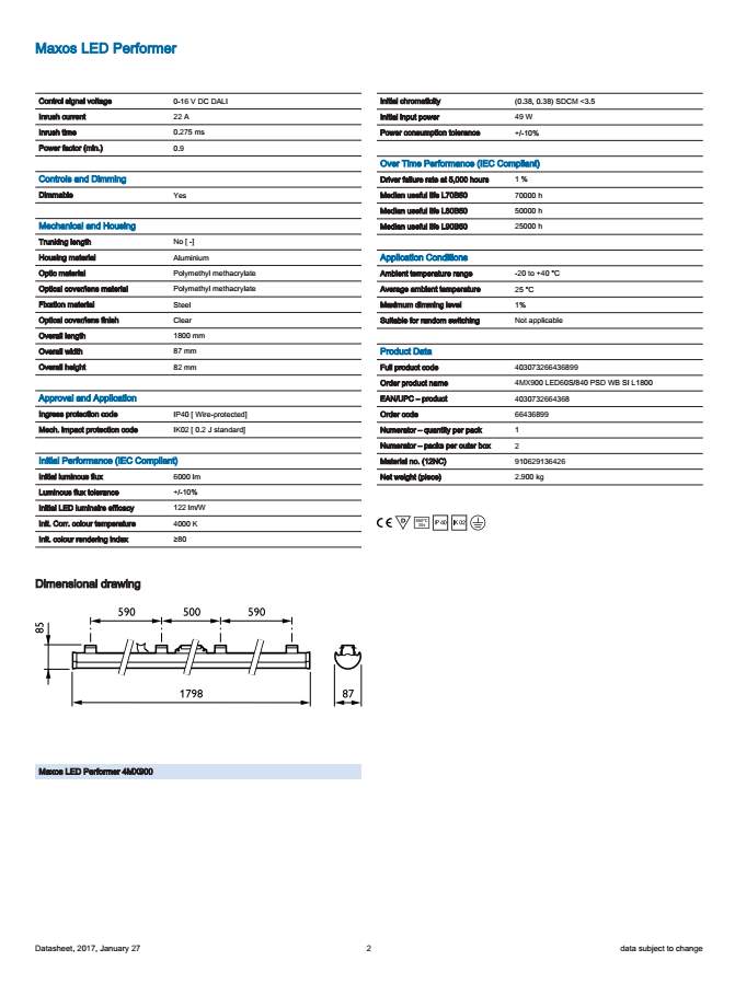
Figure 17 Philips Lighting Xitanium/Fortimo LED Drivers Indoor
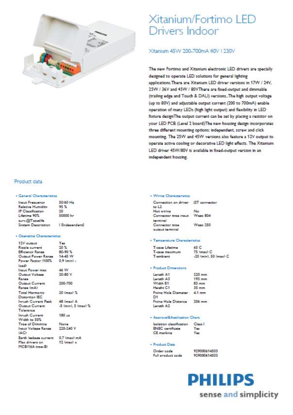
Figure 18 GE Compact Power Line CP3500 rectifier Model: J2014003
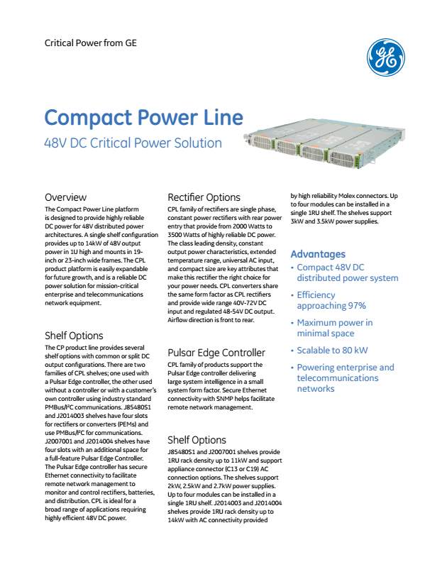
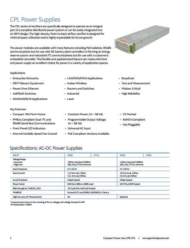
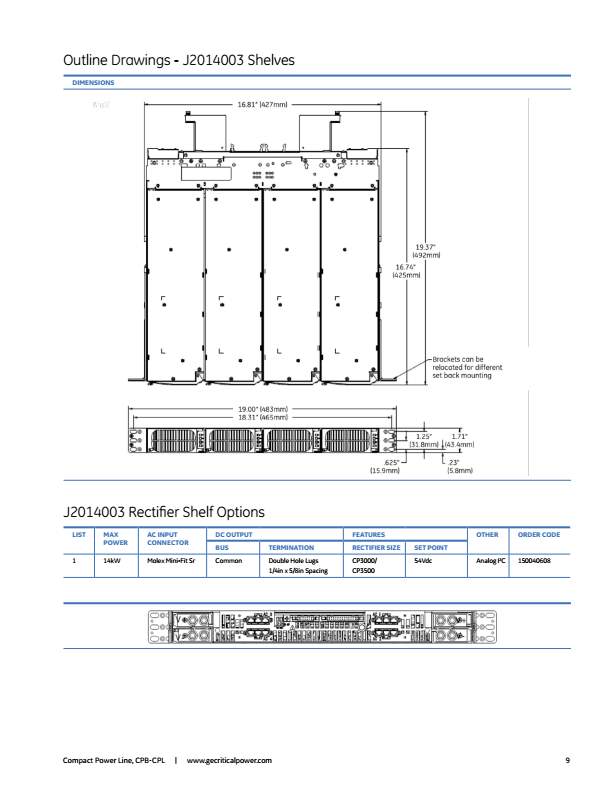
Appendix 3
Design Calculations
Figure 19 Relux Light Planning Software Calculation
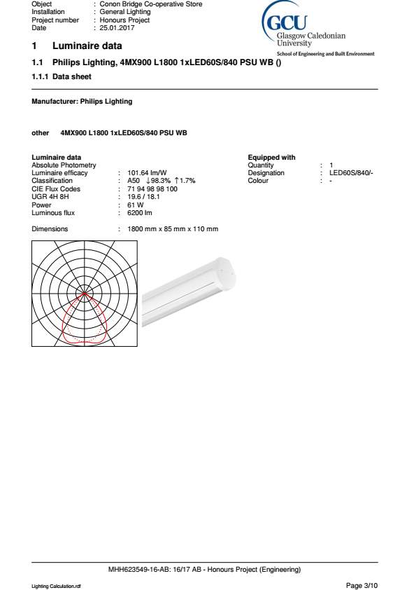
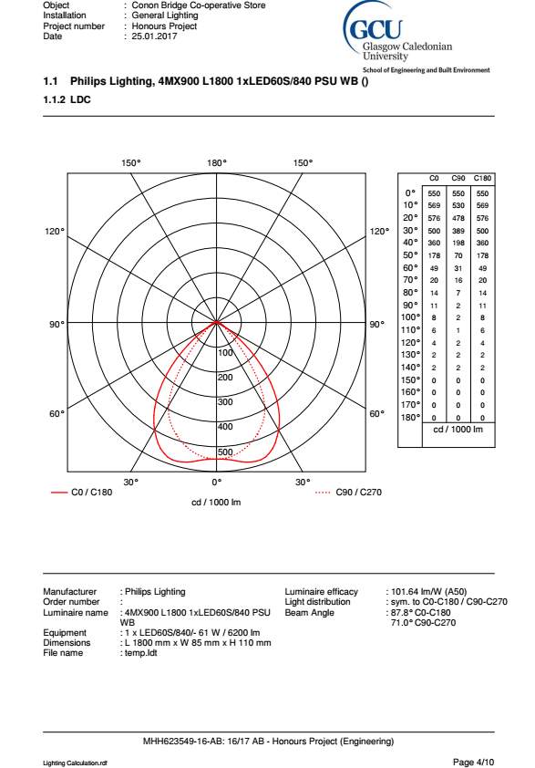
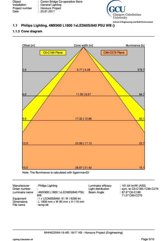
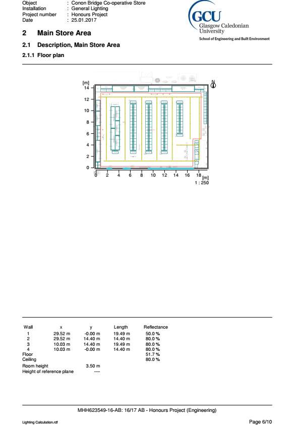
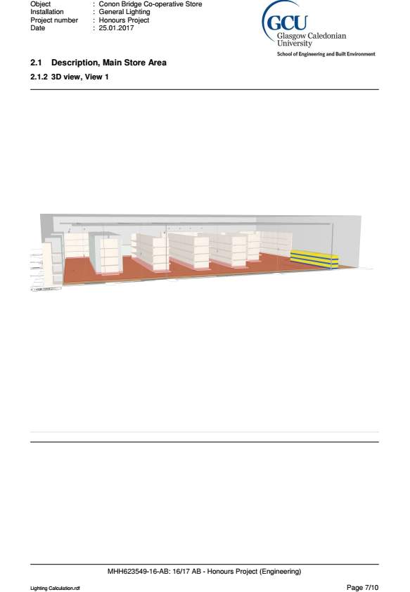
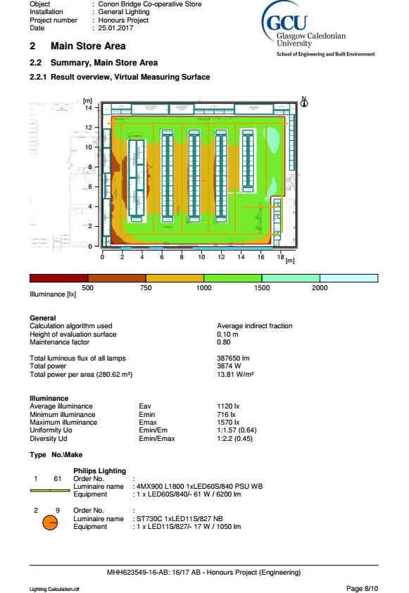
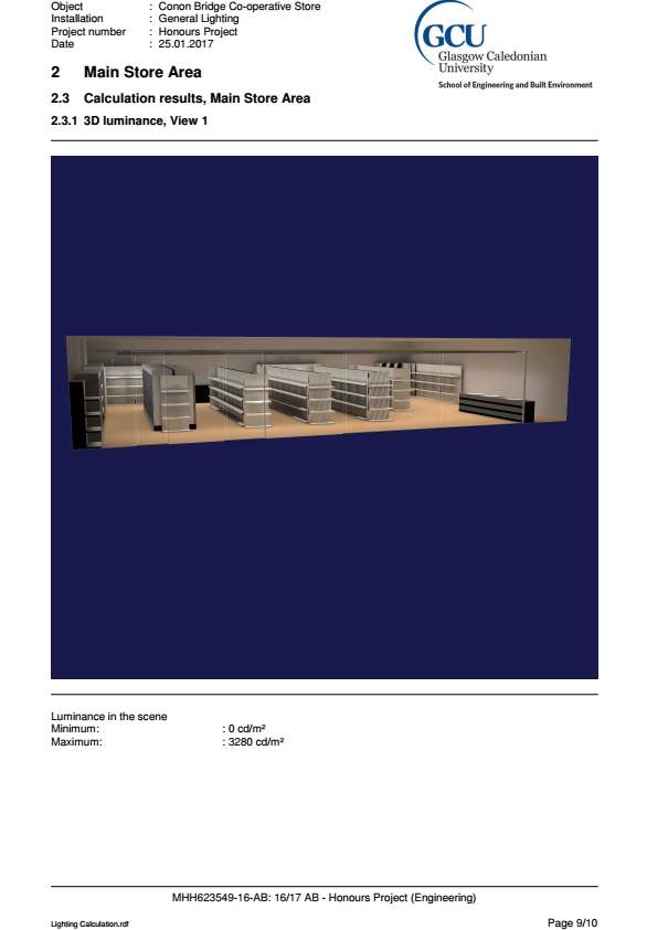
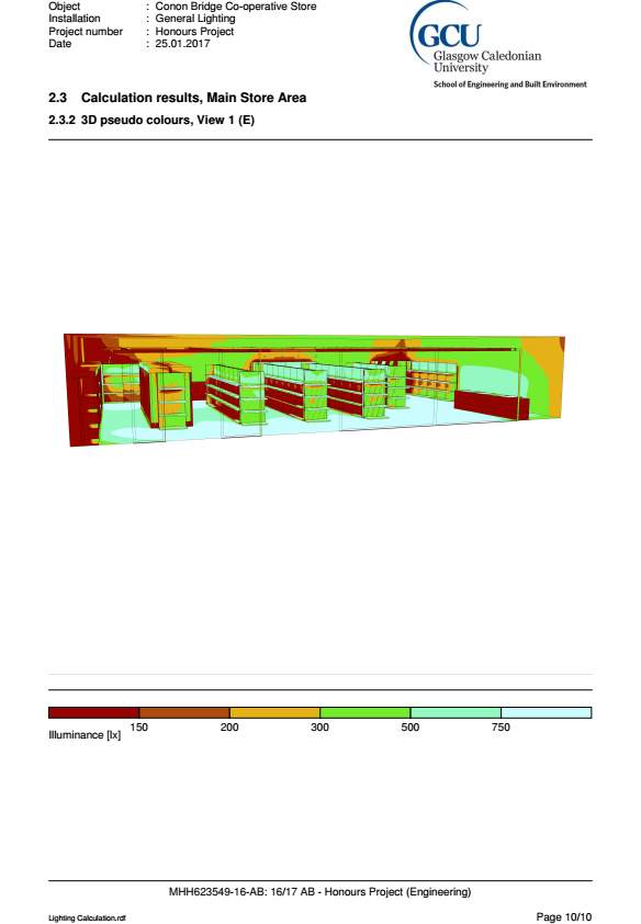
Trimble MEP ProDesign Calculation
Figure 20 AC System Cable Calculation

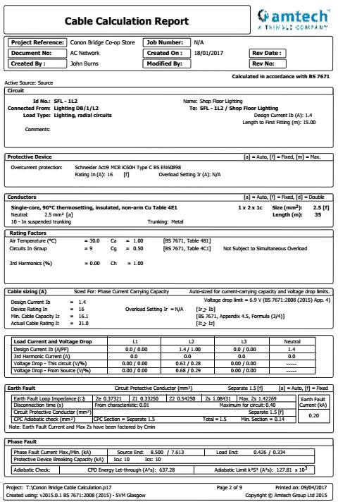
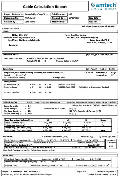
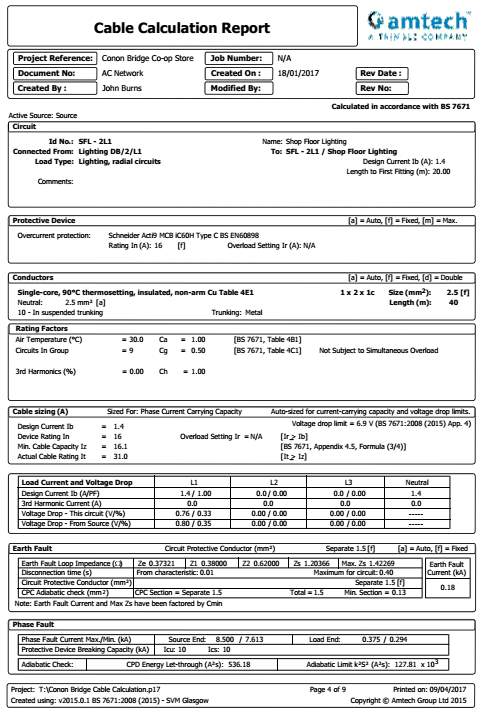

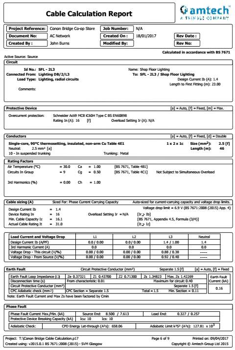
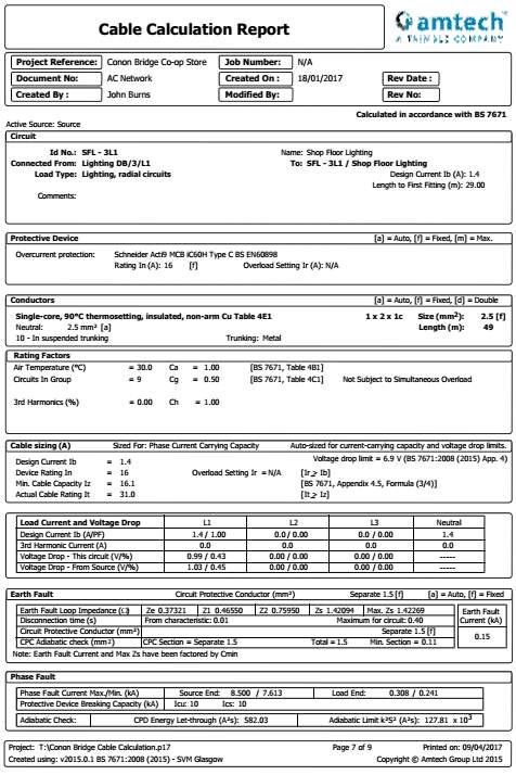
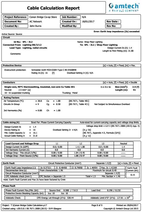

Figure 21 DC System Cable Calculation


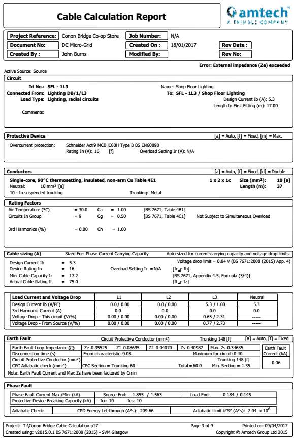


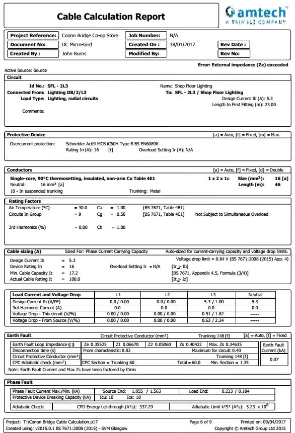


Appendix 4
Component Cost Enquiries
Figure 22 Philips Lighting 4MX900 LED Luminaire Enquiry
From: Philips Key Account Manager [mailto:-@philips.com]
Sent: 04 February 2017 21:26
To: John Burns <John.Burns@svm-glasgow.co.uk>
Cc: Regional Account Manager <-philips.com>
Subject: RE: 4MX900 LED Module Quotation
Evening John…
The typical price for the 4MX900 LED60S/840 PSD WB L1800 SI-1 module with wide beam optic finished in white. Length – 1800mm, lumen – 6000lm is £143 ex VAT.
For 57 units this would amount to a total of £8,151 ex VAT unless purchased through one of approved distributors in which a discount may apply.
As for the removal of the integral driver, a surcharge of £230 is required as the luminaire is no longer ‘off the shelf’ and considered bespoke. The price of the driver would entitle a cost saving of £35 per luminaire.
Let me know if you need anything else and I will our sales team to give you a call to formalise your quotation.
Hope this helps!
Key Account Manager
Trade
Philips Lighting UKI
Philips Lighting UK Limited
Registered Office:, Philips Centre, Unit 3, Guildford Business Park, Surrey, GU2 8XG
Registered in England No 291612
Office : 01483 446060
http://www.lighting.philips.co.uk/prof
All orders received are processed under Philips Terms & Conditions of Sale.

Figure 23 GE Compact Power Line CP3500 rectifier Model: J2014003 Enquiry
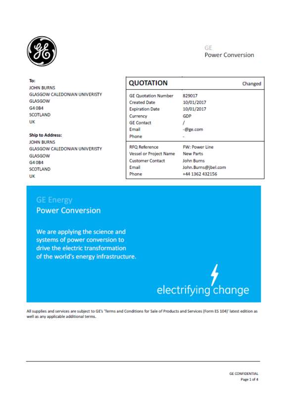
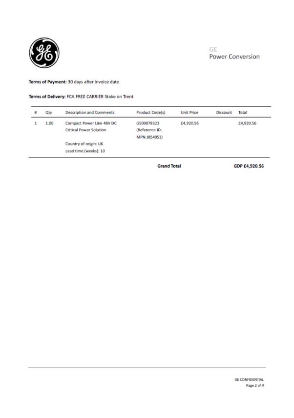

Cable Wiring
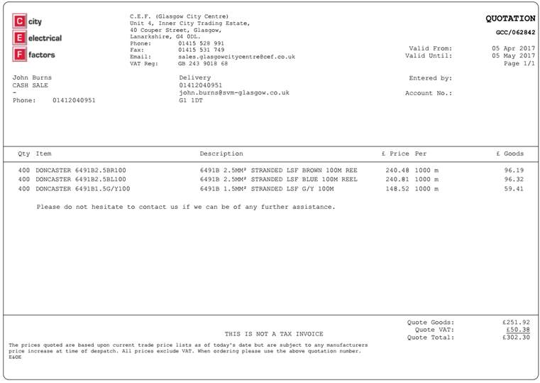
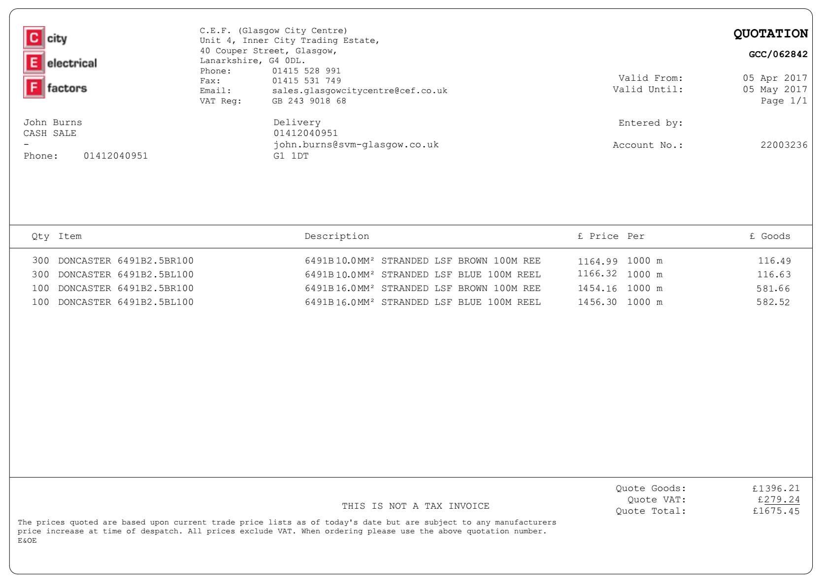
Cite This Work
To export a reference to this article please select a referencing stye below:
Related Services
View all


Related Content
All TagsContent relating to: "Electronics"
Electronics regards the science and technology involved in the development of electrical circuits and electronic devices and equipment that use them.
Related Articles

DMCA / Removal Request
If you are the original writer of this dissertation and no longer wish to have your work published on the UKDiss.com website then please: