EV Charging from Solar Powered Home Inverter
Info: 5075 words (20 pages) Dissertation
Published: 2nd Nov 2021
Tagged: EngineeringAutomotiveEnergy
Reliable and Economy Modes of Operation for Electric Vehicle-to-Home (V2H) System
Abstract
In developing countries load shedding for hours is very common. Normally, a low power backup supply is used for essential loads only, for essential lighting and fan loads. However, there is always a need for essential backup power supply for household applications.
Nowadays, rooftop, grid-connected solar inverters are being extensively used for home-based backup power supply in urban cities. Electric vehicle (EV) also become common in all over the word so charging and discharging of a huge battery of this vehicle through solar PV system are common. However, in case of a charged battery condition, as battery charging is done by the grid too, the power available from solar photovoltaic (PV) modules gets underutilized.
The proposed controllers modify the conventional, low-cost home-based inverter into a solar grid connected inverter with the ability of EV battery utilization. It has better control features which ensure the reliability of the power supply, as well as complete utilization of solar energy and the customers, need not buy a new expensive solar grid-connected inverter or any other devices to charge the EV battery if they already have a home-based inverter.
Index Terms: Backup power supply, Electric vehicle, home-to-vehicle (H2V).Solar PV system, PVgrid-connected inverter, Reliable power generation.
I. INTRODUCTION
Rapid development in the field of urbanization, industrialization and modernization has helped to increase the standards of living of the human beings but it is at the cost of high energy demand. Electrical engineering has played a vital role in this regard. Electrical energy has now become one of the basic necessities of the people for their day to day life. To fulfill their needs, the rate at which the global energy reserves of oil, gas, coal, nuclear etc. are depleting causes a worldwide concern at economical, industrial and social levels. Moreover, the consumption of fossil fuel is also related to environmental pollution and global warming. The power and energy industries are responsible for 46% of the global CO2 production while the transportation industry produces 20% [1].
The current total power generating installed capacity in India is about 343,788 MW (April 2018) and about 65% generation (222,692 MW) is coming from the thermal power plant and only 20 % is from renewable energy (69022 MW). About 2165 MW solar power plant has been installed successfully [2]. Indian government significantly expanded its solar plans, targeting US$100 billion of investment and 100 GW of solar capacity by 2022 [3] [4].
The Government of India has already taken initiatives in generating more and more power through Solar Photovoltaic (SPV). The Reserve Bank of India in April 2014 has included renewable energy projects under Priority Sector Lending for which bank loans up to a limit of ₹ 15 crores to borrowers will be available for renewable energy projects including grid-connected solar rooftop and ground-mounted systems. For individual households, the loan limit is ₹ 10 lakh per borrower.
Ministry of New and Renewable Energy (MNRE) are supplying the solar panels at a 15% incentive and encouraging the people to use it to meet their energy demand [5] [6]. Moreover, the cost of PV module is continuously being reduced and in recent past, it is reduced by 20 %.
In India, the power demand is greater than the power generation. With no or improper peak load management schemes, load shedding is very common. Regular power outage for hours creates the need for home-based standby power supply. The problem in urban cities like Aligarh is that there are about 3-4 hours of mostly scheduled load shedding over the whole year. So the people use conventional dc-to-ac inverters with a lead acid battery for the standby power supply to meet the house load demand. The availability of economical electric power is an issue of the urban area. The condition is worst where there are scheduled as well as unscheduled load shedding for more than 8 hours and for the whole area is common [7]. The availability of a reliable power supply is an issue there. With development in the technology of photovoltaic system and sharp decline in the cost of PV module, PV stand-alone inverter and PV grid-tied inverter are very common in use nowadays. They are widely used in urban as well as rural areas for a wide range of applications.
There are some drawbacks with stand-alone and grid-tied inverters as far as the home load or small load is concerned in urban areas. In grid-tied applications, the cost of the inverter is very high while in stand-alone system the reliability of the power supply is poor [8].
The commercially available solar inverters are grid-connected inverters which combine the conventional dc-to-ac inverter with a dc-to-dc buck-boost converter (maximum power point tracker) to charge the battery from solar panels. So it has two input power supply (grid and PV) to charge the battery. In most of the Indian home there is a pack of battery that is for emergency backup, so for reliable backup utilization of large size of battery is necessary that Electric Vehicle (EV) batteries can play an essential role to overcome to this problem [9]. These days utilization of EVs for transportation become common all over the world as well as India, as per the National Electric Mobility Mission Plan 2020 in India through a combination of policies aimed at gradually ensuring a vehicle population of about 6-7 million electric/hybrid vehicles in India by the year 2020 [3]. Electric vehicle batteries have massive energy storage capacity and can potentially utilize also as a backup power supply for home loads during load shedding or blackout [10].
One of the most promising ways to utilize EV without affecting on the home billing and grid stress is PV based charging of the EV that is Home-to-Vehicle (H2V) [11].
The preference of charging the battery from PV or mains depends on their voltage levels. If the voltage level of PV is greater than the rated battery voltage only then the battery gets charged from PV otherwise it will be charged from grid. In such cases most of the time PV will be underutilized even though there is some solar energy available [12]. In another case, when the battery gets discharged during evening as no solar insolation available at that time. Ultimately the battery gets charged from grid during whole night time when the power supply will be available. In the next morning the battery remains fully charged. The solar energy which would be available next morning will be unutilized or underutilized because solar power cannot be utilized for charging the charged battery.
II. Fixed Solar PV Modules
Solar insolation on the surface of PV panel depends on the declination angle (tilt angle between surface of PV module and the horizontal) of sunlight on earth (δ), latitude of the location (∅) and the inclination or tilt angle (β) of PV module with horizon [23], [24].
The declination angle varies between +23.45° to -23.45° throughout the year which is given by
δ=23.45sin360365284+n
(in degree) (1)
β=∅± δ (2)
where
n is nth day of the year starting from 1st January. In equation (2) summation is for winter and subtraction is for summer. Therefore, to harness maximum solar energy, the actual angle of inclination also varies throughout the year.
Sun tracking is a common method in a big power plant but at home scale or on a small scale it is not much desirable because of high cost of sun tracking system and complicated structure.
Thus, the inclination angle of fixed PV structure is carefully evaluated for a particular place before installation to obtain maximum overall electrical energy output. Thus, in this work, for reliable and substantial power generation in winter, the tilt angle is selected as calculated in [13]:
β=∅+15°=27.13°+15°≅42°
where
∅=27.13°is the latitude of the locality (Aligarh, India).
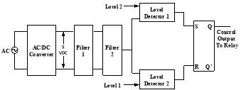
Fig. 2. Basic block diagram of mode selector.
Even though it somewhat decreases power generation in summer, but in winter the reliability of power generation increases. Therefore, in the present work,
β is kept equal to
∅+15°(i.e. 27.13°+15°), to operate PV modules in reliable mode with respect to winter.
III. Proposed Work
The problem of underutilization of solar energy in case of solar grid-connected inverter has been resolved by proposed system in this work. It comprises two controllers with a conventional home inverter and a solar charge controller plus EV as an energy storage system.
The proposed system is based on the grid-assistance, which is a combination of stand-alone and grid-connected system. It uses the benefit of both the applications as the cost of the inverter in case of stand-alone in small whereas by integrating the PV system to the grid will enhance the reliability of the power supply [14]. The customer need not buy a new inverter if they already have a home-based inverter. Thus the mode of control will be more efficient.
This system is more suitable for the urban localities where there is a power supply with few hours of load shedding. The proper and total utilization of solar energy will help in reducing the stress on the regional grid during peak hours (daytime). However, in the night and when the stored energy in the EV battery is completely exhausted, the load shedding at this condition causes complete shutdown of power supply. Therefore a low power standby power supply is required for essential/ emergency load (light, fan etc.). Moreover, for rural applications where long duration of load shedding is common, ‘reliable mode’ of operation is required. In this case battery is kept charged, either by grid or by solar energy to meet load demand in case of unscheduled load shedding.
This system is most suitable for the urban localities of developing countries where a power supply with few hours of load shedding every day is common. The proper and total utilization of solar energy will help in reducing the load demand on the utility grid during peak load hours (daytime). Thus, the system also works as peak power plant by letting off the home-load from the grid during maximum insolation hours which matches with the daily peak load hours. Thus the system works as a Home-to-Vehicle (H2V) system. However, in the night and when the stored energy in the battery is completely exhausted, the load shedding at this condition causes complete shutdown of backup power supply. Therefore, a low power standby power supply is required for essential/ emergency load (light, fan etc.).
The proposed system is designed to operate in two modes viz. reliable and economy modes. In economy mode, the main focus is to maximize the use and harness of solar energy such that no energy from solar modules remains unutilized.
While in reliability mode, the main objective is to have a reliable standby power supply available, even if the solar power is underutilized. This condition is required where scheduled and unscheduled load shedding is frequent and sometimes up to 10 to 12 hours a day. Thus, during the availability of grid power supply, the proposed system works on
A. Architecture of the proposed power system
In the proposed scheme, for harnessing total solar energy, two controllers are integrated with a solar charge controller and a single-phase conventional dc-to-ac inverter, as shown in Fig.1.
Mode selector (controller 1) is placed at the input side of the (grid) supply. It is used as selector switch which allows the charging of the battery from the grid. Source selector (controller 2) is placed at the load side. This controller is designed to schedule the supply to the home-load demand. The demand could be met from utility grid power supply or from the solar power through battery and inverter (for utilization of the solar energy). In this case, it is up to the consumers whether they want to charge the battery from solar (reliable mode) and then in case of load shedding the stored energy in battery will be utilized. Alternatively, they can use the solar energy during the day time without receiving the energy from the grid keeping the system in islanding mode. This will help to harness total solar energy and system will work in economy mode.
Optimum Voltage based Control for Reliable and Economy Mode
| VF2 VLevelDetector2
Output of LD2 Set |
VF2 VLevelDetector1
Output of LD1 Reset |
QFF(t+1) |
Mode |
| 0 | 0 | No change | – |
| 1 | 0 | Charging by mains + PV | Reliable |
| 0 | 1 | Charging by PV only | Economy |
C. Operating strategy of controllers
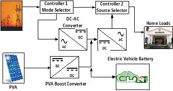
Fig. 1. Basic block diagram of the proposed gird-connected inverter based power supply.
1) Mode selector:
It consists of ac-to-dc converter which indicates the availability of grid power supply and load shedding conditions (like logic ‘1’ and ‘0’) (Fig. 2). The dc voltage is independent of the variation of the magnitude of the grid voltage due to the constant voltage from the regulator. The voltage at the output of second filter (VF2) makes the analogy with the status of availability of grid power (or level of load shedding). VF2 is the reference input voltage for both the level detectors with predefined set and reset values. These settings are related to the options of reliable power mode and economical power mode. In case of reliable power mode, battery charging is preferred for reliable backup i.e. charging is done by both utility grid and solar PV sources. For economy mode, the total power supplied to load is from the battery which has stored PV energy. Thus complete utilization of solar energy is evident and in this mode, charging of EV battery is never done from the mains.
When there are repeated and/or prolonged load shedding, this actuates the switch and thus the mains power supply starts charging the batteries. When mains power is available, VF2 continues to rise and it becomes equal to the VLevel Detector1, the output of the Level Detector 1 resets the flip-flop (Q = 0). The switch disconnects the mains and charging of battery takes place by PV only. Table I shows the control strategy for reliable and economy modes of mode selector.
During load shedding of grid power supply, VF2 starts to fall from high (saturation) value. When VF2 reaches VLevel Detector 1, the flip-flop becomes S = 0 & R = 0, and VF2 continues to fall with Q = 0 until VF2 becomes equalto VLevel Detector 2. At this point, output of Level Detector 2 becomes high and flip-flop becomes high (Q = 1) which actuates the switch in order to charge the battery from the mains (grid).
2) Source selector:
This controller is placed at the load side for connecting the load to mains (grid) or to the inverter (Fig. 3).
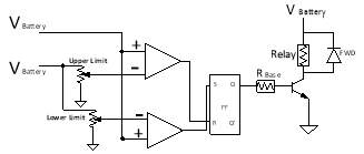
Fig. 3. Circuit diagram of source selector.
The input to this controller is the attenuated battery voltage which is fed to the level detectors along with the predefined set and reset voltages. Initially battery starts getting charged (charging may be done from grid or from the solar PV module depending upon economy or reliable modes set by mode selector). At this point the output of LD1 remains low but LD2 becomes high. The input to flip-flop is S = 0, R = 1 which resets the output (Q = 0). The output remains at this state until Vbattery = VLevel Detector 1 where S = 1 & R = 0 which sets the flip-flop (Q = 1). Once output of flip-flop becomes high, it disconnects the load from the mains (grid) and connects it to the inverter which gets power from the battery (the stored solar energy).
Now battery operates in two conditions:
Case 1: Battery gets charged and discharged simultaneously. It occurs generally in the daytime. The output of flip-flop would remain high and the load gets the power from the battery through inverter.
Case 2: battery gets discharged only. In this case battery voltage starts to fall with Q being high, until the battery voltage, VB = VLD2. At this condition flip-flop resets and thus the load gets connected to mains (grid).
IV. Modeling and Simulation of Controllers
The simulation model of controllers is developed in MATLAB®/Simulink®. The signal builder and the switch is shown in Fig. 4. are used to incorporate the load shedding pattern in the simulation circuit model.
Input to the mode selector is the load shedding pattern of the mains power supply. Simulation is done for 24 hours and accordingly the charging and discharging of output capacitor of filter 2 takes place.
While in source selector the battery voltage is represented by the signal builder and a voltage controlled source (Fig. 5). The comparator’s output is detected using the level detectors.
A. Simulation Results
As long as there is no load shedding, VF2 remains at high value and mains supply will not be utilized to charge the battery. Once there is a load shedding (Fig. 6), VF2 starts to decrease and when it reaches VLevel Detector 1, switch turns on by flip-flop which connects the mains (grid) to ac-to-dc converter. It charges the battery and the controller operates in ‘reliable mode’. When there is no load shedding, mains is available for most of the time, VF2 becomes higher than VLevel Detector 2. The mode selector disconnects the ac-to-dc converter from mains and the system operates in ‘economy mode’.
Similarly, when the battery voltage VB reaches VLevel Detector1,as shown in Fig. 6, the load gets connected to the mains and disconnected from the conventional dc-to-ac inverter. Once the battery starts get charging either from mains or PV which depends upon mode selector, VB starts rising. When it reaches VLevel Detector 2, load gets connected to the dc-to-ac inverter and it receives power from battery.
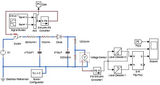
Fig. 4. Simulink model of mode selector.
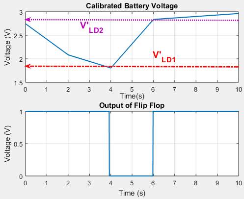
Fig. 7. Control strategy of source selector for feeding the power to the load either by PV or mains.
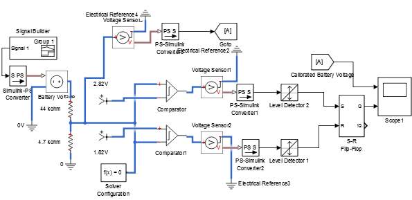
Fig. 5. Simulink model of source selector.
V. Hardware In The Loop and Experimental Setup
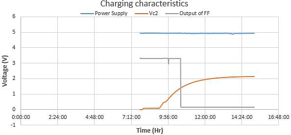
The performance characteristics of mode selector and output of the flip-flop has been recorded using the data logger as shown in Fig. 8. The charging and discharging characteristics matches with the simulation model and the flip-flop turns on the switch at the fixed predefined values. The sky blue line in Fig. 9(a), represents the presence of grid power supply. The orange line represents the capacitor voltage of filter 2. When the capacitor voltage (VF2) reaches to 1.5V in the charging mode, the output of flip-flop becomes low. This disconnects the battery from further charging through mains power supply, so the battery gets charged through solar PV modules only.
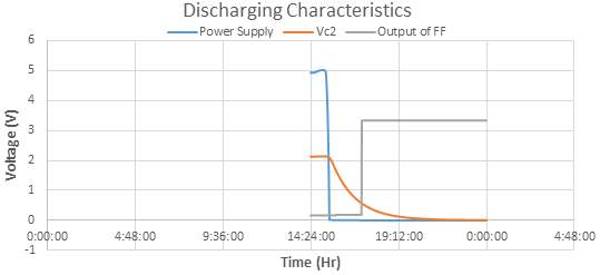
In the discharging mode (Fig. 9 (b)), when there is a load shedding condition, the VF2 starts decreasing from its saturation level and once VF2 becomes equal to 0.5V, the flip-flop becomes high and thus it turns on the switch. Now, whenever the grid power supply becomes available it charges the battery through ac-to-dc converter or utility grid.
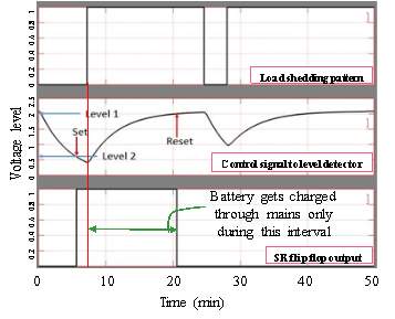
Fig. 6. Control strategy for charging the battery through mains using mode selector.
A. The experimental setup
The proposed system is implemented for the actual residential connected load of maximum 900 W. Three 250 WP rooftop solar PV modules are used (Fig. 10) and two 12 V, 200 Ah lead-acid batteries as energy storage unit. For the proposed system, a separate solar charge controller (dc-to-dc converter, 24 V and 40 A) is used. The ac-to-dc and dc-to-ac converters are used for both the configurations.
The complete experimental setup is shown in Fig. 11. The performance of a 1.44 kVA commercial solar grid-connected inverter and the proposed system are analyzed.
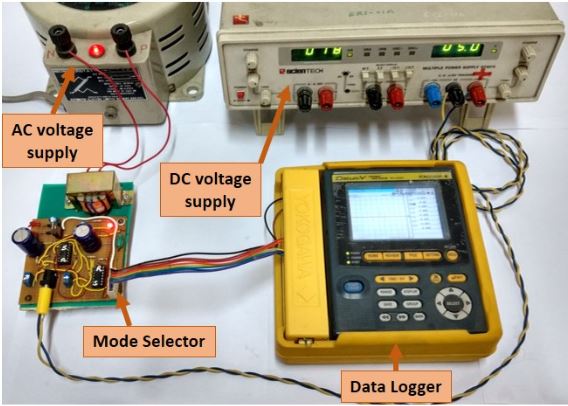
Fig. 8. Laboratory testing of Mode selector with data logger.
(a)
(b)
Fig. 9. Performance analysis of mode selector.
B. Experimental results
During the availability of utility grid power supply, it works as its normal condition of work. The PV power comes into picture usually when there is a load shedding, from 10 AM to 1 PM, solar power has been utilized when there was a load shedding, otherwise mostly mains (grid) feeds the power to the load. Moreover, when grid power supply is restored, battery gets charged through the grid only even if sufficient power is available from PV. Fig. 12, shows clearly that the PV power gets utilized during load shedding hours only and for the remaining period, grid power is used to meet the home-load power demand which is the disadvantage of the conventional solar PV inverter.
In case of the proposed system, since charging of the battery and home-load allocation is being controlled by the proposed controllers, there is complete utilization of solar PV energy. In the proposed system, under economy mode, the charging of battery and load demand are met through the solar PV only and when the insolation was negligible battery gets discharged. Once the stored energy of battery gets utilized (through inverter), thereafter the home-load switches over to grid. Figure 25 shows the performance of the proposed system in economy mode.
Source selector continuously senses the battery voltage and when VB = VLD2, the switch connects the load to inverter which utilizes stored solar energy of the battery. When sun sets, solar insolation becomes zero, the power stored in the battery is utilized till the battery voltage reaches VLD1.
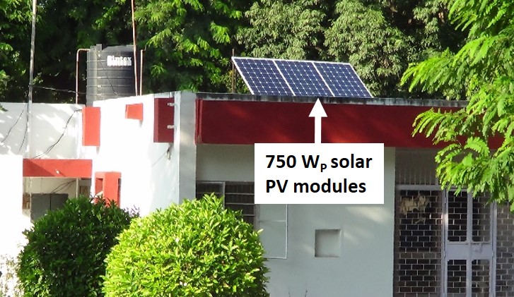
Fig. 10. Experimental setup with three 250 WP rooftop solar PV modules.
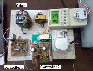
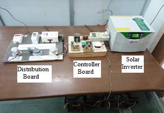
Fig. 11. Hardware setup with the developed supervisory control system.
Thereafter, the load gets connected to the mainssupply (grid).
It is evident from the Fig. 13. that PV energy has been completely utilized and charging of battery during daytime is done by PV only. PV power gets utilized as soon as the voltage level of battery reaches to the predefined set value. When the battery voltage level comes down to the preset value, the load connects to the grid or mains supply.
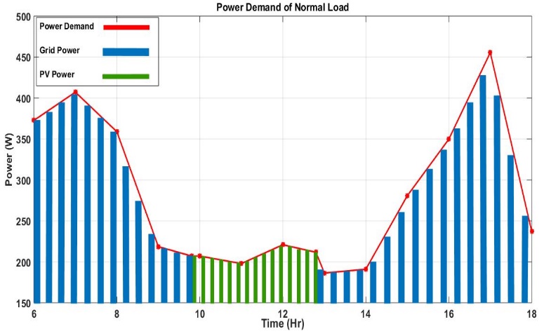
Fig. 12. A typical power demand of home load on 1st of October 2017, which is met by two different powersources a usingconventional solar-grid connected inverter.
In reliable mode, during sunshine hours the battery gets charged through both PV modules and utility grid, and the home-load demand is met through the grid. Although the home-load is using the utility grid to meet its power demand during the availability of grid power, even in that case solar energy is utilized to charge the battery.
VI. Conclusion
In this paper a supervisory control hardware is developed in which a conventional home based inverter, solar charge controller (power conditioning unit) and the proposed controller circuits are integrated together. The simulation model of proposed controllers are also developed and the performance of whole system is recorded. A prototype hardware in loop testing was done and the comparison was made between the commercially available solar grid-connected inverter and the proposed system. The results, thus obtained shows the complete utilization of solar energy in the proposed system as compare to the commercially available inverter where solar energy comes into action only when there is load shedding during sunshine hours.
Two modes of control are proposed i.e. reliable mode and economy mode, for better standby power supply and maximum harnessing of solar energy. Moreover, on the basis of reliable solar power availability in winter, an optimum tilt angle is also proposed. The proposed is based upon a very low-cost simple circuitry which does not require any type of expensive sensors to acquire the voltage or current levels. These designed controllers can be easily implemented in the existing home based inverter and utilized for solar PV based inverter at minimal cost. The proposed system has been tested successfully with the actual home loads.
References
[1] United States Environmental Protection Agency, “Global Greenhouse Gas Emissions Data | Greenhouse Gas (GHG) Emissions | US EPA,” 2017. [Online]. Available: https://www.epa.gov/ghgemissions/global-greenhouse-gas-emissions-data. [Accessed: 21-May-2018].
[2] M. of power Central Eectricity Authority, “All India Installed Capacity ( in Mw ) of Power Stations Installed Capacity ( in Mw ) of Power Utilities in the States / Uts Located in,” Cent. Eectricity Authority, Minist. power, Gov. India, vol. 4, pp. 1–7, 2018.
[3] Government of India, “National Electric Mobility Mission Plan : Department of Heavy Industry, Ministry of Heavy Industries & Public Enterprises,” NIC, New Delhi, 2015. [Online]. Available: http://dhi.nic.in/UserView/index?mid=1347. [Accessed: 22-May-2018].
[4] A. Ahmad, Z. A. Khan, M. Saad Alam, and S. Khateeb, “A Review of the Electric Vehicle Charging Techniques, Standards, Progression and Evolution of EV Technologies in Germany,” Smart Sci., vol. 6, no. 1, pp. 1–18, Jan. 2017.
[5] RBI|Notification, “Reserve Bank of India – Notifications,” Rbi, 2014. [Online]. Available: https://www.rbi.org.in/scripts/NotificationUser.aspx?Mode=0&Id=6017. [Accessed: 21-May-2018].
[6] M. Gupta, Y. Rafat, and M. S. Alam, “Well to Wheel Cum Tailpipe Emission Analysis : ICE vs xEV,” no. May 2016, 2017.
[7] S. S. Raza, I. Janajreh, and C. Ghenai, “Sustainability index approach as a selection criteria for energy storage system of an intermittent renewable energy source,” Appl. Energy, vol. 136, pp. 909–920, 2014.
[8] F. Ahmad and M. S. Alam, “Economic and ecological aspects for microgrids deployment in India,” Sustain. Cities Soc., vol. 37, pp. 407–419, Feb. 2018.
[9] M. Shafaati Shemami, M. Saad Alam, and M. S. J. Asghar, “Fuzzy Control Assisted Vehicle-to-Home (V2H) Energy Management System,” Smart Sci., pp. 1–15, Dec. 2017.
[10] M. S. Shemami, M. S. Alam, and M. S. J. Asghar, “Load shedding mitigation through plug-in electric vehicle-to-home (V2H) system,” in 2017 IEEE Transportation and Electrification Conference and Expo, ITEC 2017, 2017, pp. 799–804.
[11] H. Shin and R. Baldick, “Plug-In Electric Vehicle to Home (V2H) Operation under a Grid Outage,” IEEE Trans. Smart Grid, vol. 8, no. 4, pp. 2032–2041, 2017.
[12] S. Khan, A. Ahmad, F. Ahmad, M. Shafaati Shemami, M. Saad Alam, and S. Khateeb, “A Comprehensive Review on Solar Powered Electric Vehicle Charging System,” Smart Science, vol. 6, no. 1, pp. 1–26, 02-Jan-2017.
[13] S. M. Amrr, M. S. Alam, M. S. J. Asghar, and F. Ahmad, “Low cost residential microgrid system based home to grid (H2G) back up power management,” Sustain. Cities Soc., vol. 36, pp. 204–214, Jan. 2018.
[14] M. Shafaati Shemami, M. Saad Alam, and M. S. J. Asghar, “Reliable residential back up power control system through Home to Plug-in Electric Vehicle (H2V),” Technol. Econ. Smart Grids Sustain. Energy, 2018.
Cite This Work
To export a reference to this article please select a referencing stye below:
Related Services
View all


Related Content
All TagsContent relating to: "Energy"
Energy regards the power derived from a fuel source such as electricity or gas that can do work such as provide light or heat. Energy sources can be non-renewable such as fossil fuels or nuclear, or renewable such as solar, wind, hydro or geothermal. Renewable energies are also known as green energy with reference to the environmental benefits they provide.
Related Articles
DMCA / Removal Request
If you are the original writer of this dissertation and no longer wish to have your work published on the UKDiss.com website then please: