Feedback Forms Development Using Application Development Framework (ADF)
Info: 11251 words (45 pages) Dissertation
Published: 11th Dec 2019
Tagged: Information Technology
A Project Phase-II Report on Report Generator -II
ABSTRACT
Usually any organization or a firm needs a report or a feedback concerning to a specific issue. That is where we make use of forms to conduct survey which can be reviewed later. Here we use JDeveloper, Oracle database, Microsoft Access Database to execute our requirement. The basic idea is that a form is generated as per our requirement and user gives his feedback where admin can have a look into it. The login depends on his role. If he is a user it takes him to the forms. If he is an admin he can watch the feedback data. A Sign Up page is also provided for a new user to register. A download option is provided to admin in order to download the data in either excel format or as mdb file. Bootstrap styling is also done in order to give a good user interface. Finally mdb files are converted into oracle database. User can select the form for which he wants to give feedback. Similarly admin can select the form to view or download data.
CONTENTS
| Sl. No.
|
Details | Page No. |
| 1 | INTRODUCTION | 1 |
| 2
2.1 2.2 |
SYSTEM ANALYSIS
Existing System Proposed System |
2
2 2 |
| 3 3.1 3.2
3.3 3.4 3.5 3.5.1 3.5.2 3.5.3 |
SYSTEM REQUIREMENTS
Hardware Requirements Software Requirements H/W System Configuration S/W System Configuration Modules Of The System User Admin Sign Up |
3
3 3 3 3 3 4-5 6-7 8-9 |
| 4
4.1 4.2 4.3 |
SYSTEM STUDY
Economic Feasibility Technical Feasibility Social Feasibility |
10
10 10 10 |
| 5
5.1 5.2 5.3 5.4 |
SOFTWARE ENVIRONMENT
Java JDeveloper Microsoft Access Database HTML and Bootstrap |
11
11 12-25 26 26-31 |
| 6
6.1 6.2 6.3 6.4 6.4.1 6.4.2 6.4.2.1 6.4.2.2 6.4.2.3 6.4.2.4 |
SYSTEM DESIGN
Input Design Output Design System Architecture UML Concepts Building Blocks Of UML UML Diagrams Use Case Diagram Class Diagram Sequence Diagram Activity Diagram |
32
32-33 33 34-35 36 36-39 40-43 40 41 42 43 |
| 7
7.1 7.2 7.3 7.4 7.5 |
SYSTEM TESTING
Types Of Tests Unit Testing Integration Testing Acceptance Testing Test Cases |
44
44-45 46 46 46 47-49 |
| 9 | RESULTS AND ANALYSIS | 50-59 |
| 10 | CONCLUSION AND FUTURE SCOPE | 60 |
| 11 | REFERENCES | 61 |
FIGURES
| SI.NO
Figure 3.5.1.1 Figure 3.5.1.2 Figure 3.5.2.1 Figure 3.5.2.2 Figure 3.5.3 Figure 6.3 Figure 6.4.1 Figure 6.4.2 Figure 6.4.3 Figure 6.4.4 Figure 6.4.5 Figure 6.4.6 Figure 6.4.7 Figure 6.4.8 Figure 6.4.2.1 Figure 6.4.2.2 Figure 6.4.2.3 Figure 6.4.2.4 Figure 8.1.1 Figure 8.1.2 Figure 8.2.1 Figure 8.2.2 Figure 8.2.3 Figure 8.2.4 Figure 8.2.5 Figure 8.3.1 Figure 8.3.2 Figure 8.4 |
Figure
User Login Survey Form Signup Request In Admin Feedback Data Signup page Architecture Of System Classes Use Cases Nodes Messages Dependencies Association Generalization Realization USE CASE DIAGRAM CLASS DIAGRAM SEQUENCE DIAGRAM ACTIVITY DIAGRAM Login Page Invalid Page Selection Of Survey Survey Form Validation Of Survey Error Message Success Message Signup Requests in Admin Page Feedback Data Signup Page |
Page No
5 5 7 7 9 35 37 37 38 38 39 39 39 39 40 41 42 43 50 51 52 53 54 55 56 57 58 59 |
- INTRODUCTION
In this project we developed dynamic forms for feedback or report generation using Application Development Framework (ADF). We made use of JDeveloper, Oracle database, Microsoft Access Database to execute our requirement. The basic idea is that a form is generated as per our requirement and user gives his feedback where admin can have a look into it. A JavaEEapplication server called integrated web logic server is used which is developed by Oracle Corporation. The login into it depends on his role. If he is a user it takes him to the forms. If he is anadmin he can watch the feedback data. We make use of mdb files for all data insertions and selection for the forms. A SignUp page is also provided for a new user to register. Light Weight Directory Access Protocol (LDAP) is used for automatic generation of username if the user is already logged into the system. A download option is provided to admin in order to download the data in either excel format or as mdb file. Bootstrap styling is also done in order to give a good user interface. Finally mdb files are converted into oracle database. User can select the form for which he wants to give feedback. Similarly admin can select the form to view or download data.
- SYSTEM ANALYSIS
2.1Existing System:
The system is usually done using JavaScript or AngularJS including CSS and HTML which involves many lines of code and takes a lot of time to do it.
2.2Proposed System:
This can be done using ADF where there are no repeated lines of code, bootstrap can be included with much ease and UI can be created just with drag and drop and their functionalities can be done easily from the palettes.
Advantages:
1) This helps in completion of project in quick time which is required in the industry.
2) Data can easily be brought from the database.
3) It is simple and has less amount of errors in it.
4) End to end coverage like(MVC, security, customization).
Disadvantages:
1) User Interface cannot be as good as that of done with HTML and Bootstrap.
2) Integrated Web Login Server takes lot of time as the whole application is run and deployed every time we run it.
- SYSTEM REQUIREMENTS
3.1Hardware Requirements:
- PC or Laptop with minimum 2 GB RAM
- 64bit/32bit operating system
3.2Software Requirements:
- TOOLS/PLATFORM- JDeveloper, Oracle 11g, Microsoft Access Database
- LANGUAGE/COMMANDS-Java, HTML, Bootstrap
3.3H/W System Configuration:
PROCESSOR- Intel (R) Core (TM) i5-4200
SPEED – CPU @1.60 GHz 2.30GHz
RAM – 2GB(min)
HARD DISK – 1TB
3.4S/W System Configuration:
OPERATING SYSTEM: WINDOWS95/98/2000/XP/7/8/8.1
FRONT END : Java Server Faces
BACK END : Java
3.5Modules of the System:
The System consists of:
- User
- Admin
- Sign Up
3.5.1User:
User’s Username is retrieved using LDAP if he is an existing user. A role based login is provided, so that the user is directed to survey interface or admin interface based upon his designation upon entering right credentials. User can choose any number of surveys from the available surveys and give his opinion.
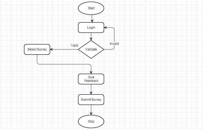
Data Flow Diagram for User Module
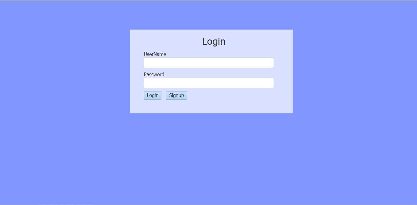
Figure 3.5.1.1
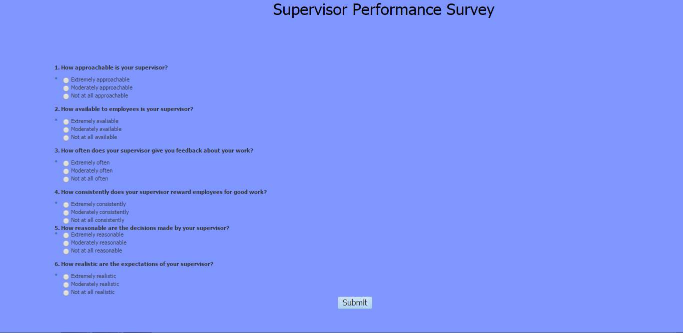
Figure 3.5.1.2
3.5.2 Admin:
Admin is like the heart of the application. Whenever a new user registers to give the survey, admin has to approve his registration. Admin should also set the designation of the new user based upon which his access privileges are decided. If he is given a normal user as designation then he can only give opinion to surveys. If he is given HR or admin as designation then he can view the data collected from the survey.
Another crucial role of the admin is to monitor the data collected from the users and provide the data as viewable content as well as downloadable file.
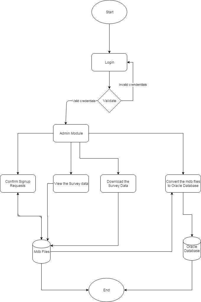
Data Flow Diagram for Admin Module
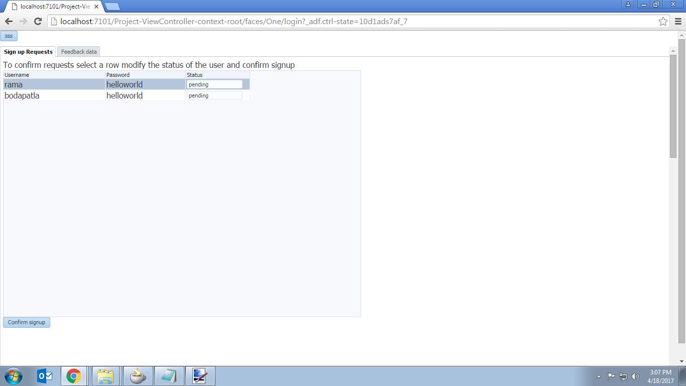
Figure 3.5.2.1
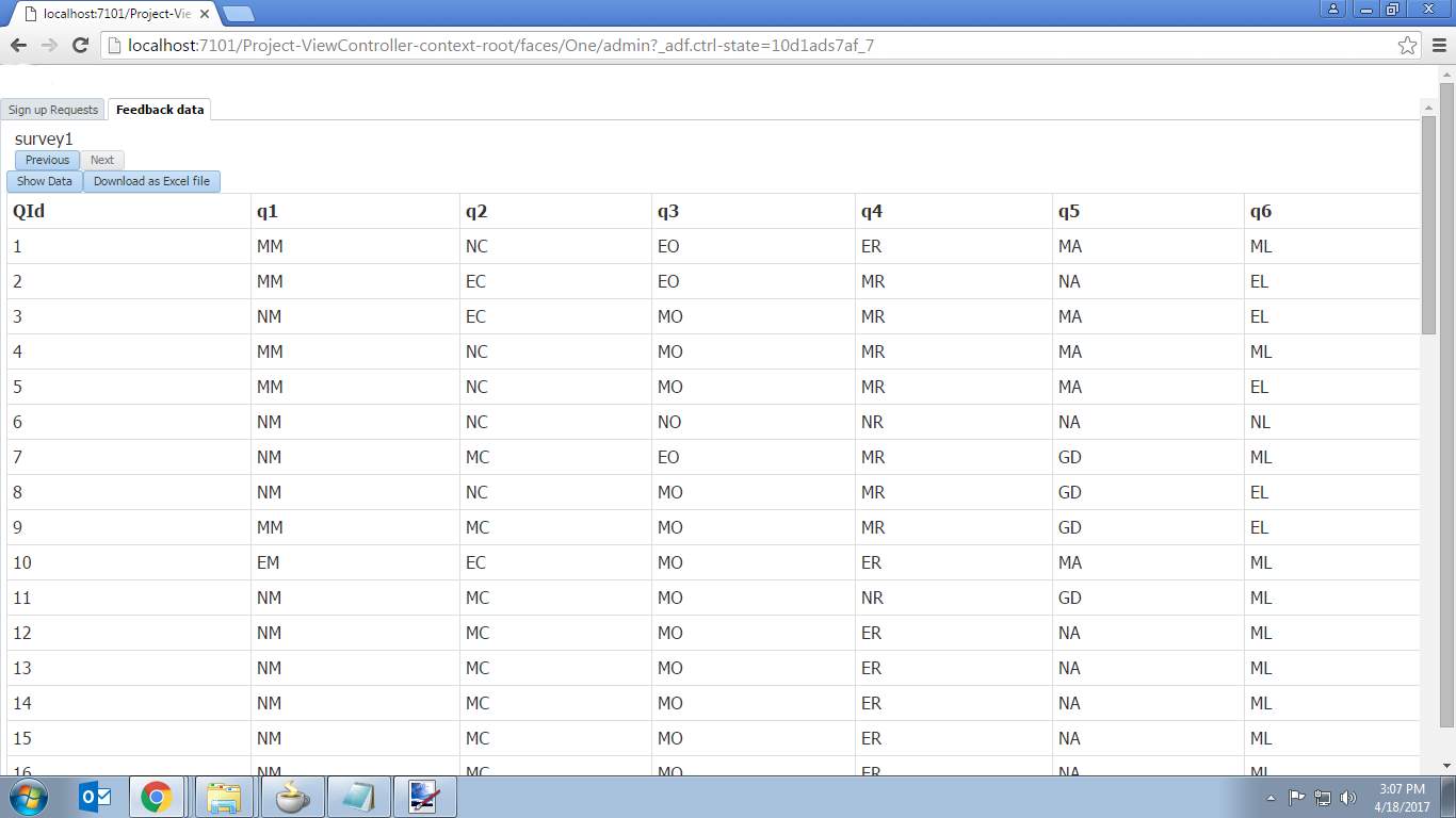
Figure 3.5.2.2
- Sign Up:
When a user is new to the application then he/she should register by providing a unique username, valid password and wait for the admin to approve his/her registration.
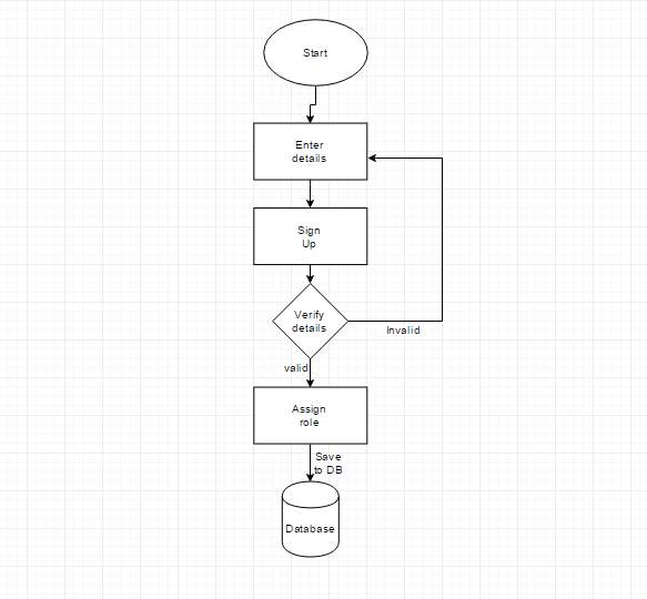
Data Flow Diagram for Sign Up Module
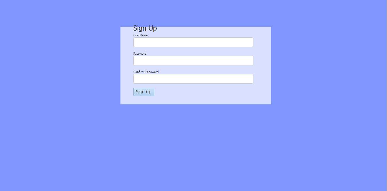
Figure 3.5.3
- SYSTEM STUDY
FEASIBILITY STUDY:
The project’s feasibility is analyzed here and a proposal is put forth with a very plan for the project and cost estimates. The proposed system’s feasibility study is carried out. This is done to make sure that it doesn’t become a burden to the company. Major requirements of the system understanding is essential for feasibility analysis.
The things we need to consider in the feasibility analysis are:
- ECONOMICAL FEASIBILITY
- TECHNICAL FEASIBILITY
- SOCIAL FEASIBILITY
4.1 ECONOMICAL FEASIBILITY: Economic impact that system has on the organization is studied. The funding that the company can invest in the research and development is limited. The amount spent must be well balanced.
4.2 TECHNICAL FEASIBILITY: Technical feasibility study is carried here, that is, the technical requirements of the system. The system developed must have a less or moderate demand on the available resources or else this will lead to high demands on the available technical resources. This gives rise to high demands being pushed on to the client. Thus developed system must have an appropriate requirement, as only less or null changes are required for implementing this system.
4.3 SOCIAL FEASIBILITY: This is to study the acceptance level of the system by the user. This involves the training process of the user to efficiently use the system. He must be encouraged so that he can be able to do some criticism, which is well received, as he is the one who finally uses the system.
5. SOFTWARE ENVIRONMENT
5.1 JAVA:
It is a computer programming language which is object-oriented, and designed to have less implementation dependencies. The developers “write once, run anywhere”, meaning that compiled Java code will run on every platform which supports Java without the requirement of compiling again. Nowadays, it is one of the popular programming languages in use for client-server web applications. It was initially developed by James Gosling. Much of its syntax come from C and C++.
Java Platform:
Java’s design goal is portability. It is done by compiling or converting Java code to in between representation called Java bytecode, instead converting to machine code.
It has standard libraries which gives a way to access features such like graphics, threading, and networking.
Performance:
Initially the programs which are run on the platform are slow than C++. Its speed improved with the initiation of just-in-time compilation which supported inner classes, the StringBuilder class, optional assertions, etc. The performance was further improved with the adding of the java.util.concurrent package, including ConcurrentMaps and other multi-core collections.
5.2 JDeveloper:
JDeveloper is a free software IDE provided by Oracle Corporation. It is like that of eclipse which has features for advancement in XML, Java, JavaScript, SQL and PL / SQL, HTML, BPEL and PHP. It covers the development cycle from design to coding, debugging, optimization and profiling to deployment.
With JDeveloper, Oracle aims to simplify application development, focusing on a visual and declarative application development approach, as well as creating an advanced encoding environment.
The IDE kernel exposes an API that other Oracle teams use to build extensions to JDeveloper. BPEL, Portal, Business Intelligence and other Oracle components build their design-time tools on JDeveloper
The JDeveloper code editor offers a rich set of encoding functions, which include visual and non-visual features that provide different views of the code. The software provides functionalities that guide the use of Java EE components.
Declarative features allow programmers to generate table-based EJBs or POJOs in relational databases. JDeveloper fluidly automates the creation of Java EE artifacts. For example, with a single click on any visual artifact you can convert a Java class into a web service. JDeveloper generates the related Web Services Descriptive Language (WSDL) document and related JAX-RPC components.
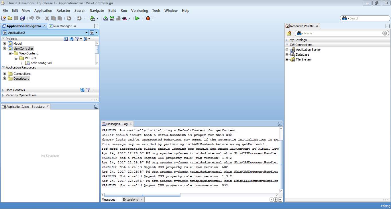
Oracle JDeveloper 11g
Various Palette’s in JDeveloper:
Component Palette: It consists of components like button, input text, output text,radio buttons and layouts like panel,panel stretch ,panel tabbed and so on.
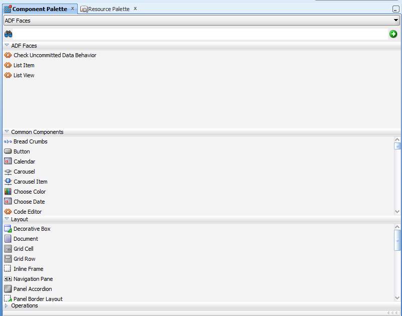
Component Palette
Resource Palette: It has various catalogs and IDE connections.
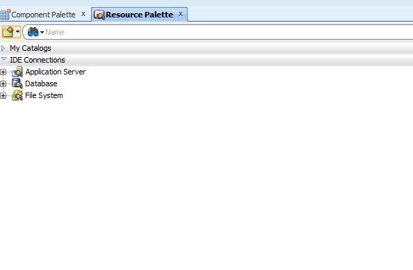
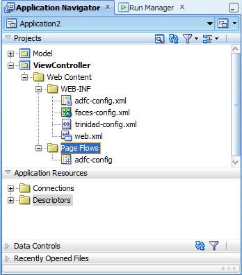
Application Navigator: Navigate through various layers (Model, View, Controller).
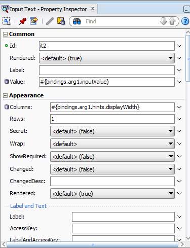
Property Inspector: Various component’s properties can be modified here.
ADF Architecture with Business Components
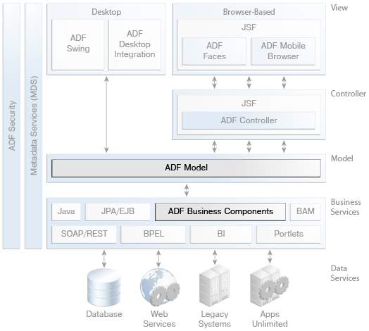
The Controller Layer
The controller layer manages the application flow and controls input given by the user. For example, when a search button is clicked on any page,it is the controller which determines what action to perform (search) and where to navigate (result page).
There are two driver options for web-based applications in JDeveloper: the standard JSF driver or the ADF driver that extends the functionality of the JSF driver. Regardless of the driver you use, you will usually design your application flow by displaying the pages and navigation rules in a diagram.
With the ADF controller you can break the flow of your application into smaller, reusable workflows; Include non-visual components such as method calls and decision points in their flow; And create “page fragment” streams that run within a region of a single page it contains. This approach encourages maximum reuse of fragments of the user interface and simplified integration into portals and mash up applications.
The View Layer
The View layer represents the user interface of the application. Oracle ADF supports multichannel access to enterprise services, which allows you to reuse your business services and access them from a Web client, a client-server tilted desktop-based application, Microsoft Excel spreadsheets, or mobile devices such as a smartphone. For the Web-based interface, Oracle ADF offers more than 150 Ajax-enabled JSF components that simplify the task of creating of dynamic and interactive user interfaces.
The Model Layer
The model layer connects objects to the business services that use them in the other layers. Oracle ADF provides a model layer implementation that sits above the business services, to provide a single interface that can be used to consume any type of business service. The model layer consists of two components, data controls and data links, which use metadata files to define the interface. Data controls summarize the implementation details of customer business services. Data bindings expose data control methods and attributes to user interface components, providing clear separation between the view and the model. Because of the metadata architecture of the model layer, developers get the same development experience by linking any type of implementation of the Business Service layer to the View and Control layers.
About ADF Business Components
ADF Business Components is a way of creating reusable business services with minimal coding from the developer side. Developers can use visual wizards and editors provided by ADF to create ADF Business Components services without writing any Java code. It is also possible to extend ADF Business Components main classes to create more functionalities. ADF Business Components services are embedded through the ADF model for use in the view layer of the application.
Please note that the features of ADF Business Components directly incorporate the ADF model.
In addition, you can expose the applications created with ADF Business Components as services that can be used by other Fusion web applications, composite applications which follow Service Component Architecture (SCA), and other applications through web service calls.
Core Benefits of ADF Business Components
ADF Business Components provides the following benefits to enterprise service developers:
• Management of access to databases, including connection, data recovery, locking records and inserting and updating records.
• Ability to create data models adapted to specific types of end users, with only the necessary data exposed.
• Creating relationships of data models in addition to those defined by the database.
• Ability to use declarative rules to enforce mandatory fields, primary key uniqueness, data scale accuracy, and foreign key references.
• Capture and application of simple and complex business rules, programmatic or declarative, with multi-level validation support.
• Implement the query data filter for example end-user without code.
• Ability to expose components as services that can be integrated with other Fusion web applications and consumed by SOA composite applications.
• Ability to raise business events to start business processes and trigger the synchronization of external systems.
• An integrated application state management facility that enables application failover and user session management across multiple nodes in clustered and highly available server environments.
• Performance oriented optimization functions such as shared application modules for handling static data and grouping of application modules.
• Visual assistants and editors in JDeveloper that generate XML definitions for components that can also be edited manually.
Key Components of ADF Business Components
The ADF Business Components architecture consists of the following main components:
- Entity objects, which wrap up individual objects into a data source, such as tables in a database, and adds logic to work with that data.
- Associations of entities that define the relationships between the objects of individual entities.
- View objects that provide access to data in a form that can be used via an ADF model binding in a user interface. View objects enable data retrieval based on an entity object.
- View links, which define the main detail hierarchies between view objects.
- Application modules, which require the view objects required for a logical work unit associated with an end user task that is used for running our application.
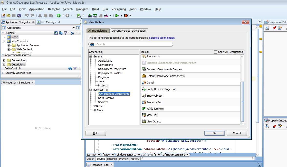
Entity Objects
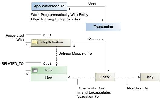
ADF entity objects are business components that encapsulate data, persistence behavior, and business rules for the elements that are used in the application. For example, entity objects can represent: • Elements of the logical structure of the business, such as product lines, Clubs, sales and regions • Business documents, such as invoices, change orders and service requests • Physical items, such as warehouses, members and equipment Entity objects are mapped to individual objects in the data source. In the vast majority of cases, these are tables, views, synonyms or snapshots in a database. For example, you can create an entity object named Clubs that represents a database table named CLUBS. Advanced programmers can base entity objects on objects from other data sources, such as spreadsheets, XML files, or plain text files.
Entity Object Within the ADF Business Component Architecture
View Objects
ADF view objects are business components that collect data from the data source, configure data for use by clients, and allow clients to change that data in the ADF Business Components cache. Among other things, a view object definition can gather the necessary information to:
• Fill a single table element in a form
• Create and process an insert or edit form
• Create a list of values to fill a drop-down list
• Create a search form with specific search criteria
Once you have created a view object definition and included it in the data model of an application module, use the Data Controls panel to create user interface components based on collections, attributes, and operations of view object.
View Object Within The ADF Business Component Architecture
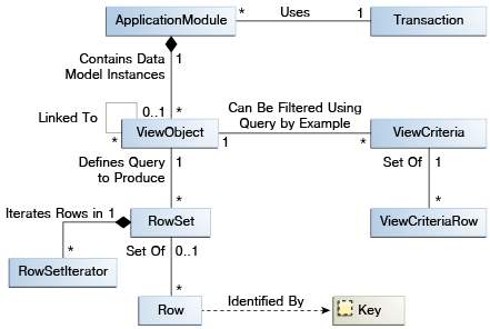
Types of View Objects
There are two main types of sight objects:
• Entity-based view objects that access data from one or more entity objects and coordinate with those entity objects to update the data source based on the user’s actions.
• Read-only view objects, which have direct access to the data. Because read-only view objects do not require intermediate objects, they access data more quickly than feature-based view objects. Create read-only view objects if you have use cases where you need to access the data without modifying them. You can have a read-only view object and an entity view object for the same table.
In addition, you can create view objects with other data sources such as:
• Direct database SQL queries
• Programmatic sources
• Static data from CSV files
You can also create polymorphic view objects, which represent several types of row sets with a common inheritance hierarchy in a single view object.
View Links
The relationships between view objects are handled by view links, which define a relationship between two view objects based on sets of entity attributes of each. Like entity associations, these can range from simple one-to-many relationships based on foreign keys to complex multi-to-many relationships.
Individual instances of view objects can also be related by individual instances of view links, which create a master-detail relationship between query result sets. For example, suppose you have definitions of view objects that represent a club information query and an member information query, and a view link between view objects that represent the relationship between a club and its members. If an instance of the previous view object definition, allClubs, is related to an instance of the latter, membersInClubs, for an instance of the view link, those instances will be synchronized: whenever a particular row of allClubs is selected, membersInClubs only will show Details for that row.
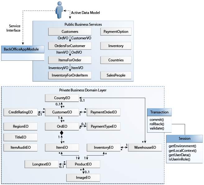
Application Modules
Oracle ADF application modules are the implementation of ADF Business Components from the ADF model data controls. Application modules represent specific application tasks. The application module definition provides a data model for the task by adding the view object and viewing the necessary link instances for the task. It also provides services that help the client to perform the task. For example, an application module can represent and assist with tasks such as:
• Updating customer information
• Create a new order
• Processing of salary increases
Application Module Within the ADF Business Component Architecture
5.3 Microsoft Access Database:
Microsoft Access is a Microsoft Database Management System (DBMS) that combines the Microsoft Relational Jet database engine with a graphical user interface and tools required for software development
Microsoft Access stores data in a format on its own based on the Access Jet database engine. It can also link directly or import to data stored in other databases and applications.
Data architects, software developers and worldly users can use Microsoft Access to develop application software. Just like other Microsoft Office applications, Access is also supported by Visual Basic for Applications (VBA), an object-based programming language that can refer to a variety of objects including ActiveX Data Objects, Data Access Objects (DAO) and many other ActiveX components. Visual objects used in forms and reports expose their methods and properties in the VBA programming environment, and VBA code modules can declare and call
operations of Windows operating system.
.mdb is the file extension used in certain versions of Microsoft Access databases to store the tables of data. At present .accdb extension is in use.The macro language is enhanced to support even more sophisticated programming logic and database level automation.
5.4 HTML and Bootstrap:
HTML:
Hypertext Markup Language (HTML) is the default markup language for web development to create static web pages. It is combined with JavaScript and Cascading Style Sheets for the web development. Web browser gets HTML documents from a web server or from a local store and place them in multimedia web pages.
HTML elements are much required for HTML pages. It provides a way of structured creation of documents called structural semantics for text such as headings, paragraphs, lists, links, citations and other items. HTML elements are bounded by tags written in pointed brackets.
Tags like <img /> and <input /> directly to the page content. Others, like <p> … </ p>, and provide information about the text of the document, and may contain other labels than sub-elements. The browser does not display HTML tags, but uses it to interpret the content of the page.
Bootstrap:
Bootstrap is to create a free web site framework and open web front-end and web applications. It involves HTML and CSS templates for typography, shapes, buttons, navigation, and other interface components. Here only front-end development is concerned.
Bootstrap is the second strongest point in the GitHub project with more than 107,000 stars and 48,000 branches.
Bootstrap is modular and consists of several style sheets that implement the various components of the kit. These style sheets are usually packaged together and include web pages, but can include individual components or delete them. Bootstrap offers a set of configuration variables that control things like color and filling of different components.
Components Of Bootstrap:
Container:
Bootstrap also requires a containing element to wrap site contents.
There are two container classes to choose from:
- The container class will give a responsive fixed width container.
- The container-fluid will give a full width container.
In Bootstrap, each webpage can be divided into rows and column-grids, and each row has 12 column-grids.
To create a row in Bootstrap, .row class needs to be used. Syntax:<div class=”row”>
To create a column in Bootstrap, .column class needs to be used.syntax: To create a column in Bootstrap, .col-<sq>-<n> class needs to be used.
Size qualifiers can be of four types:
- lg (for large devices with screen width >= 1200px)
- md (for medium devices with screen width < 1200px and >=992px)
- sm (for small devices with screen width < 992px and >=768px)
- xs (for extra small devices with screen width < 768px)
Number of grids in a column can range between 0 to 12.
When we want spaces between columns then we can do this by using .col-<sq>-offset-<n> class.
Navigation Bar:
It is a navigation header placed at the page top.
This can extend or collapse as the likes of screen size.
This can be done as follows <nav class=”navbar navbar-default”>.
Inverted Navigation Bar:
This is the inverse of nav bar. This gives a black color.
This can be done by converting navbar-default class into .navbar-inverse.
Bootstrap Tables:
A normal Bootstrap table has horizontal dividers and light padding.
The table class is added to give styles to table
Bordered Table:
The .table-bordered class adds borders on all sides of the table
Hover rows:
The .table-hover class adds a grey background color on rows of the table.
Condensed Table:
This class makes a table by reducing cell padding in half.
Responsive Table:
This class gives a responsive table. The table can be scrolled horizontally on small devices i.e devices less than 768px. While on large devices there is no difference.
Colors:
<p class=”text-muted”> no color will be displayed.
<p class=”text-primary”> blue color will be displayed.
<p class=”text-success”> Green color will be displayed.
<p class=”text-info”> Light blue color will be displayed.
<p class=”text-warning”> Orange color will be displayed.
<p class=”text-danger”> Red color will be displayed.
<p class=”text-white”> White color will be displayed.
Forms:
| Class | Usage | Can be Used In |
| form-group | For group of form controls | Use with any block-level element e.g:<fieldset> or<div> |
| form-control | Text usage inputs | text, date-time, password etc |
| Select menu | size | |
| Textareas | —– | |
| form-control-file | File inputs | file |
| form-check | Checkboxes and radios | —– |
Checkboxes and radios
Disabled checkboxes and radios are supported, but to provide a not-allowed cursor on the hover of a parent<label>, you need to add the .disabled class to the parent .form-check. The disabled class will also lighten the text color to indicate the input’s state.
Control sizing
Set the height using classes like .form-control-lg, and set the width using grid column classes like .col-lg-*
Readonly inputs
Add the readonly boolean attribute on an input component to prevent the modification of input’s value. Read-only inputs appear lighter ( like disabled inputs), but retain the standard cursor.
Column sizing
Wrap the inputs in grid columns, or any custom parent element, to easily enforce desired widths for the components.
Help text
Block-level help text can be created by using .form-text (previously known as .help-block in v3). Inline help text can be flexibly implemented using inline HTML elements and utility classes like .text-muted.
Block level
Block help text for below inputs or for longer lines of help text—can be achieved easily with .form-text. This class includes display: block and adds some top margin for easy spacing from the above inputs.
Inline
Inline text can typically use any of the inline HTML elements (be it a <small>, <span>, or something else).
Validation
This has styles for danger, warning, and success states on the form controls.
Defining states
- Danger state is used when there is a compulsory or blocking field. User must fill the field to submit the form.
- Warning state for values that are in progress, before a user attempts to submit a form.
- Success state is used for ideal situations.
Select menu
This needs only a class called .custom-select.
<select class=”custom-select”>
<option selected>See menu</option>
<option value=”11″>hai</option>
<option value=”34″>hello</option>
<option value=”56″>admin</option>
</select>
6. SYSTEM DESIGN
6.1 INPUT DESIGN
The input design is the link between the information system and the user. It includes the development specification and data preparation procedures and steps required to enable transaction data in a useful form for processing can be achieved by inspecting the computer to read or read data from a written or printed document To test the data directly in the system. The design of the input focuses on controlling the required input, checking the errors, preventing delay, preventing extra steps and keeping the process simple. The input is designed to provide security and ease of use while maintaining privacy.
Input Design considered the following:
- What data should be given as input?
- How should the data be controlled or encoded?
- The dialogue to guide the operating staff in delivering input.
- Methods for preparing input validations and steps to follow when an error occurs.
OBJECTIVES
1. Input design is the process of converting a user-oriented description of the input into a computer-based system. This design is important to avoid errors in the data entry process and to show the correct address to the management to obtain correct information of the computerized system.
2. It is achieved by creating easy-to-use screens for data entry to handle large data volume. The goal of designing the input is to facilitate data entry and be error-free. The data entry screen is designed in such a way that all manipulated data can be made. It also provides disk viewing facilities.
3. When entering the data, it will check its validity. The data can be entered with the help of screens. Appropriate messages are provided as necessary when the user will not be in instant maize. Therefore, the purpose of the input design is to create an input design that is easy to follow.
6.2 OUTPUT DESIGN
A quality output is one that meets the requirements of the end user and presents the information clearly. In any system, processing results are communicated to users and to another system through outputs. The output design determines how the information is to be shifted for the immediate need and also the output of the printed copy. It is the most important and direct source information for the user. The efficient and intelligent output design improves the system’s relationship to help the user’s decision making.
1. The design of computer production should proceed in an organized and well thought-out manner; The correct output must be developed ensuring that each output element is designed in such a way that people find that the system can use easily and effectively. When designing computer output design, they should identify the specific output that is needed to meet the requirements.
2. Select methods for presenting information.
3. Create documents, reports, or other formats that contain information produced by the system.
The output form of an information system must achieve one or more of the following objectives.
- Transmit information on past activities, current status or projections of the future.
- Point out important events, opportunities, problems or warnings.
- Activate an action.
- Confirm an action.
6.3. SYSTEM ARCHITECTURE
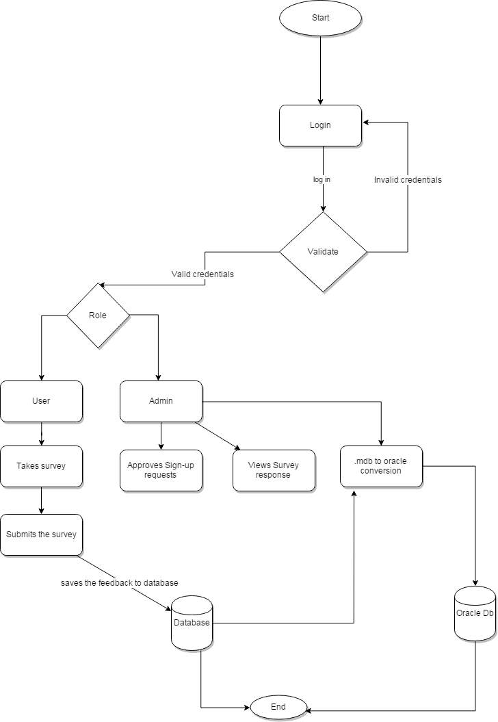
Figure 6.3:ARCHITECTURE OF SYSTEM
The above diagram shows the architecture of our project Face Recognition Using Python. It shows how our system is designed and shows the flow among various elements throughout the system in an abstract view.
6.4 UML Concepts
A language has become necessary for overview or blue prints of the software. Then Unified Modelling Language(UML) was introduced. This is used for:
- Visualizing
- Specifying
- Constructing
- Documenting the artifacts
This provides rules and the vocabulary for combining words in that vocabulary for interaction purpose. This deals with System representation in conceptual and physical way. System can be well understood by this modelling.
6.4.1 Building Blocks of the UML
The vocabulary of the UML comprises of three kinds of building blocks:
- Things
- Relationships
- Diagrams
Things are the abstractions that are first-class components in a model; relationships hold these things together; diagrams group related collections of things.
1. Things in the UML
There are four kinds of things in the UML:
- Structural things
- Behavioral things
- Grouping things
- Annotational things
Structural things are the nouns of UML models. The structural things used in the project design are:
First of all, a class is a description of a set of objects that share common attributes, relationships, operations and semantics.
| Window |
| Origin
Size |
| open()
close() move() display() |
Figure 6.4.1: Classes
Secondly, a use case is a description of a series of actions which is performed by system that provides a perceptible result of the value to a particular actor.

Figure 6.4.2: Use Cases
Thirdly, a node is a physical element that exists at runtime and represents an arithmetic source, which generally has a bit of memory and often processes capacity.
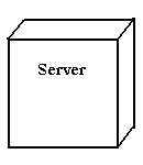
Figure 6.4.3:Nodes
Behavioral things are the dynamic parts of UML models. The behavioral things used are:
Interaction:
An interaction is a behavior that consists of a set of messages exchanged under a set of objects in a particular context to achieve a specific purpose. An interaction includes a number of other elements, including messages, action sequences (the behavior that is conveyed by a message, and links (the connection between objects).

Figure 6.4.4: Messages
2. Relationships in UML:
There are four kinds of relationships in UML:
- Association
- Generalization
- Dependency
- Realization
A dependency is a semantic relationship between two things in which a change in one thing may affect the semantics and behaviour of the other thing (dependent thing).

Figure 6.4.5:Dependencies
An association is a structural relationship describing a configured link, a link that is a connection between objects. Aggregation is a special kind of association, which represents a structural relationship between an entity and its components.

Figure 6.4.6:Association
A generalization is a specialization or a generalization relationship in which objects of the specialized element (the child) can be substituted for objects of the general element (the parent).

Figure 6.4.7:Generalization
A realization is a semantic relationship between classifiers, where in one classifier specifies a contract that another classifier guarantees to carry out.

Figure 6.4.8:Realization
6.4.2 UML DIAGRAMS:
6.4.2.1. USE CASE DIAGRAM
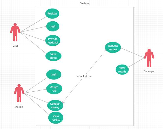
Figure 6.4.2.1:USE CASE DIAGRAM
The above diagram is Use Case diagram of our system. It shows the set of actions performed by various users. In our system we have twousers. They are administrator/user and anonymous one. As described earlier, the content in the Ovals are actions performed in the system and those actors are like symbols represent users in system. Those dashed lines from user to action means users are performing those actions respectively.
6.4.2.2. CLASS DIAGRAM
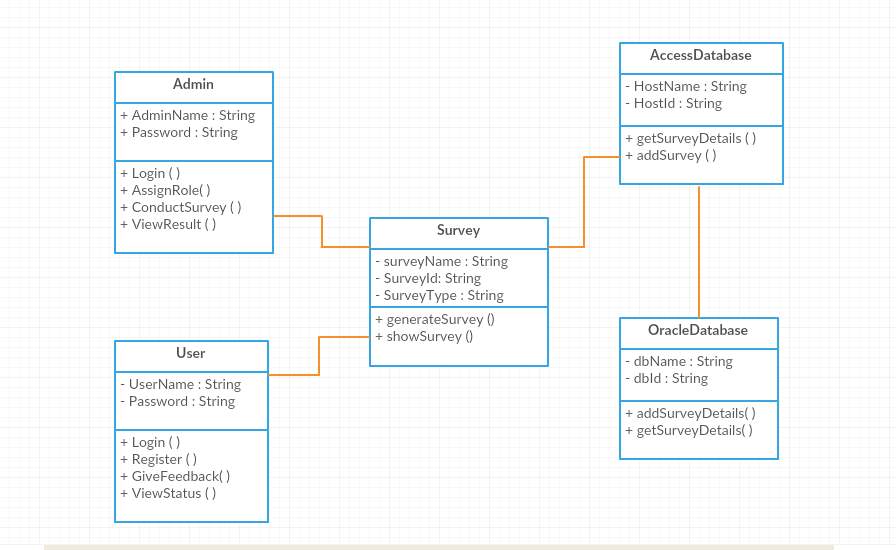 Figure 6.4.2.2:CLASS DIAGRAM
The above diagram represents class diagram of our system i.e., it shows various classes used in our system and the relationship with one class to other in the system. Each rectangle box represents a class and the upper portion of it represents class name and middle portion represents attributes of the class and the lower represents the functions performed by that class.
6.4.2.3.SEQUENCE DIAGRAM
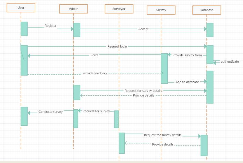
Figure 6.4.2.3: SEQUENCE DIAGRAM
The above diagram Show sequence diagram. It represents sequence or flow of messages in system among various objects of the system in life time. The rectangle boxes at top represent objects that are invoked and the dashed lines dropping from those boxes are life lines which shows existence of the object up to what time. The boxes on the dashed lines are events and the lines connecting them represent messages and their flow.
6.4.2.4. ACTIVITY DIAGRAM
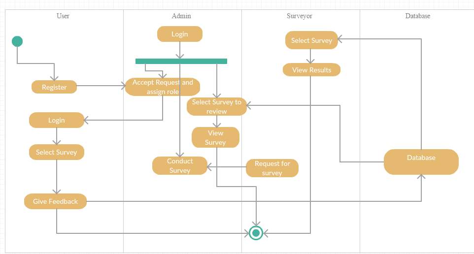
Figure 6.4.2.4: ACTIVITY DIAGRAM
The above diagram represents activity diagram of the system i.e., it represents the flow of activities in our project. Dot at the start represents starting and dot with circle represents ending and an activity is represented as curve sided rectangle. On seeing it we can understand the flow activities that has to be gone from start to end.
7. SYSTEM TESTING
Errors can be found using this testing. Product’s functionality can be tested using their components and their integration. This testing makes sure that user expectations and requirement doesn’t fail. Different testing types are:
7.1 TYPES OF TESTS
1. Unit testing
The test cases checks whether our logic is correct or not, which gives valid output for out inputs.
All decision and internal code flow branches must be validated. It is the testing of individual software units of the application independently. It is done after completion of an each individual unit before integrating with other unit. It is a structural test, which is based on the knowledge of its construction and is invasive. Unit testing performs basic component-level testing to test specific business process, application, and / or system configuration that is developed. Unit testing ensures that each unique process of a business process is developed accurately with the documented specifications and contains clearly requirements and expected results.
2. Integration testing
This testing is done to test software components whether they actually work together as a whole or not. The tests are event driven and are more concerned with the basic result of screens or fields. The integration tests show that although the components were individual satisfaction, as demonstrated by the successful unit test, the combination of components is correct and consistent.
3. Functional test
This test will give orderly demonstration that have tested functions available, such as commercial and technical requirements specified, system documentation and instruction manuals.
This testing is done on the following:
- Valid Input : Accepting of valid input must be done.
- Invalid Input : Rejecting of invalid input must be done.
- Functions : Functions which are identified need to get exercised.
- Output : Application outputs must be exercised.
- Systems/Procedures: Systems or procedures need to get invoked.
4. System Test
This makes sure that integrated software whether meets the requirement or not. Set up is tested to get actual and expected results. Configuration-oriented system integration testing is an example of system testing. System tests depends on descriptions and process flows, with emphasis on pre-driven process linkages and integration points.
5. White Box Testing
Here software tester has idea about the internal working, language and structure of the software. It is the inverse of black box testing and will check the areas where black box testing can’t be done.
6. Black Box Testing
Here tester doesn’t have any idea of internal working or language of the project. This is kind of testing where the software is considered a black box, that is you can’t “see” in it. The tester gives inputs and appropriate outputs are checked without seeing working of the system.
7.2 Unit Testing:
Individual units are tested.
Objectives of the Test:
• Proper working of entries of the field.
• Links for the pages are correct or not.
• Delayed screen or messages must not come.
Features to be tested
• Duplicates should not be allowed
• Links should take to correct page.
7.3 Integration Testing
Integration test software tests are incremental integration of two or more components into a single software platform integrated failures caused by defects in the interface caused. The task of the integration tests is that to verify components or software applications are- a level higher – level software applications companies – error free interaction.
Test Results: Defects are not present. Test cases passed successfully.
7.4Acceptance Testing
This is very important testing which requires involving of end users. This testing makes sure that functional requirements are met.
Test Results: Defects are not present. Test cases passed successfully.
7.5 Test Cases:
Table 7.1 Test Cases for Home Module
Home Module:
| TEST CASE NUMBER | TEST CASES | EXPECTED OUTPUT | ACTUAL OUTPUT |
| 2. User Registration | 1. If valid details are given
2. If valid details are not given |
Registration Successful
Registration Unsuccessful |
Registration Successful
Registration Unsuccessful |
| 3.Admin Login validation | 1. Username and Password are valid
2. Username and Password are invalid |
Login Successful
Login Unsuccessful |
Login Successful
Login Unsuccessful |
- Author : D. J. Pranay Teja
- Tested By : B. Rama Krishna
- Subsystem Name : Home
- Functionality Tested : Login
- Test Data :
Test ConditionS:
Table 7.1 Test Conditions for Home Module
| S.No: | Condition to be tested | Expected Result | Test Cycle |
| 1 | Valid username and password. | Display the survey page of the application | PASSED |
| 2 | Invalid username or password. | Display the same login page prompting the user to give valid credentials. | PASSED |
Admin Module:
Table 7.2 Test Cases for Admin Module
| TEST CASE NUMBER | TEST CASES | EXPECTED OUTPUT | ACTUAL OUTPUT |
| 1. Signup requests
approval |
1. Username and Password are valid
2. Username and Password are invalid |
Login Successful
Login Unsuccessful |
Login Successful
Login Unsuccessful |
| 2. Views the submitted feedback data. | 1. Selecting a feedback and viewing the feedback data. | Accessing the feedback data | Accessing the feedback data |
1. Author : D. J. Pranay Teja
- Tested By : B. Rama Krishna
- Subsystem Name : Admin
- Functionality Tested : Login
- Test Data :
Test Conditions:
Table 7.3 Test Conditions for Admin Module
| S.No: | Condition to be tested | Expected Result | Test Cycle |
| 1 | Selection of a survey feedback. | Display the respective survey data | PASSED |
| 2 | Approving signup requests. | On setting the user role, once user logs in,user should be directed to his respective survey page. | PASSED |
8. RESULTS AND ANALYSIS
1) Login Page:
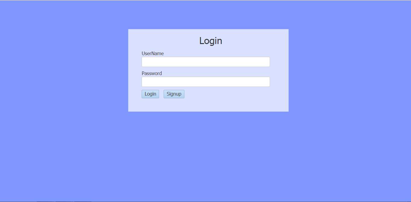
Figure 8.1.1
A role based login is done here. After entering username and password if login button is pressed, login is done based on his role of user or admin. If it is a user it takes them to feedback pages where he can gives his feedback. If it is an admin the flow goes to admin page where admin can see users and feedback data.
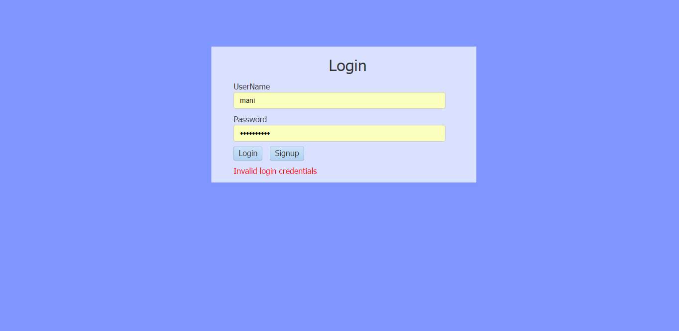
Figure 8.1.2
If username or password is entered wrong, an invalid message is displayed on the screen.
2) User Page:
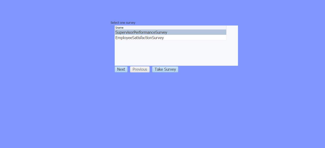
Figure 8.2.1
User selects the feedback for which he wants to give.
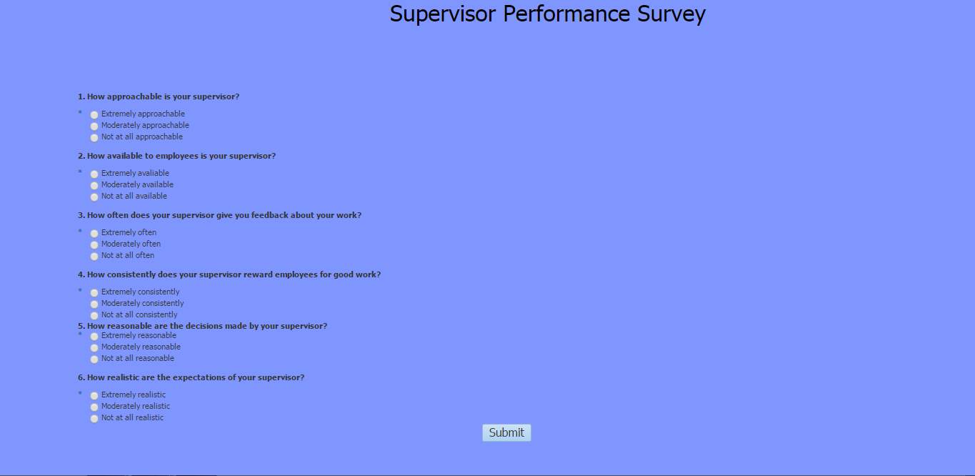
Figure 8.2.2
User gives the feedback and submits it. The data of feedback gets stored in mdb files which can be accessed by the admin.
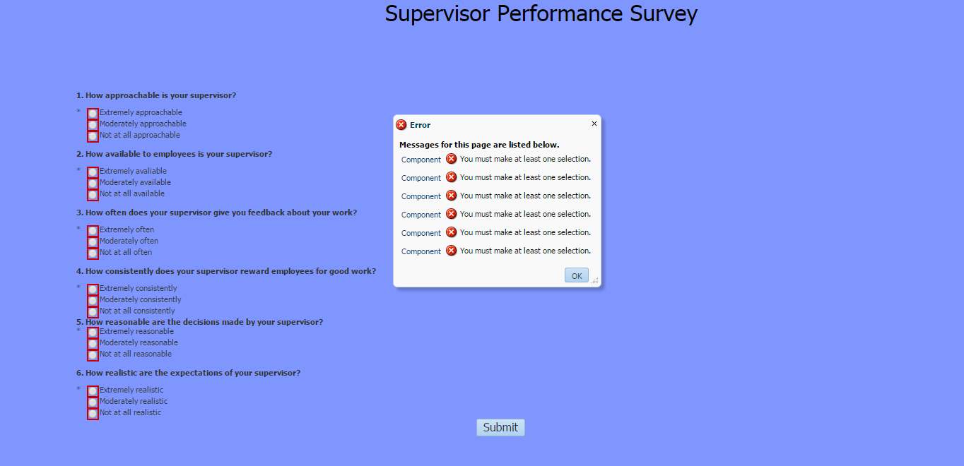
Figure 8.2.3
Validations done for the form fields as per the requirement.

Figure 8.2.4
If there is any error while submitting the form, an error message is displayed as above.
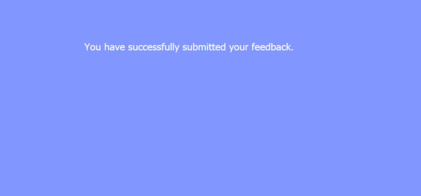
Figure 8.2.5
After submitting feedback success page as above is displayed on the screen
3) Admin Page:
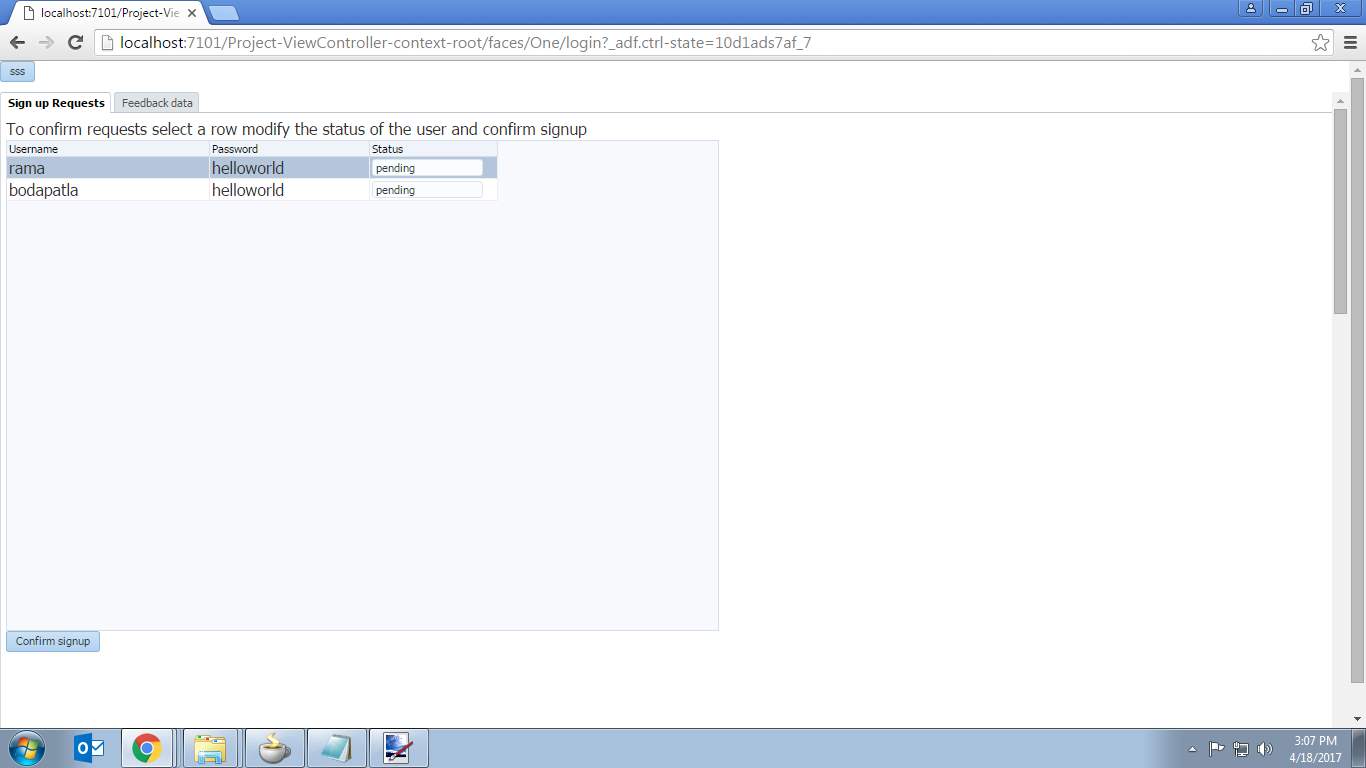
Figure 8.3.1
Admin confirms the sign up requests of the users and can access the feedback data given by the users and can also download the data of definite feedback required.
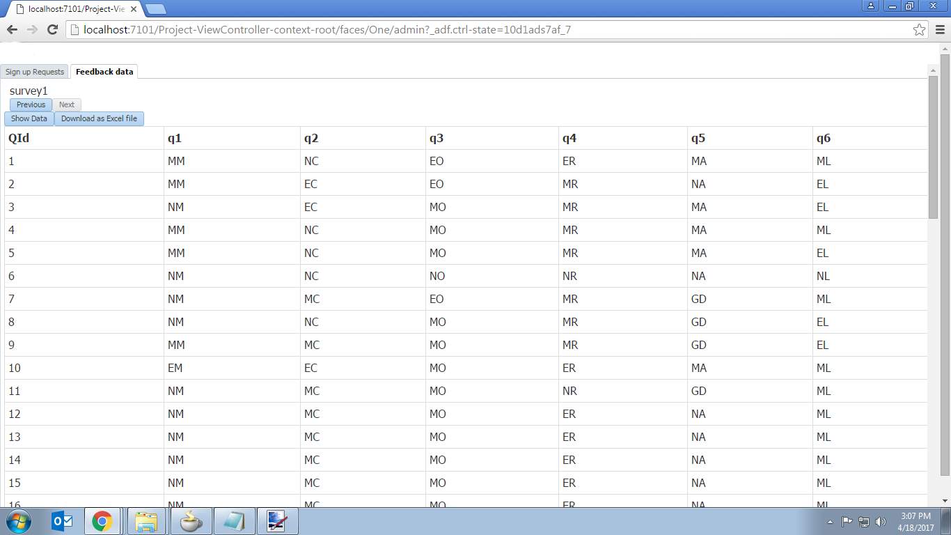
Figure 8.3.2
Admin can see the feedback data of different surveys as displayed above. He can download the feedback data as either excel or as mdb files.
4) Sign Up Page:

Figure 8.4
When sign up button is pressed it takes to the page displayed as above. The one who wants to sign up enters his details. After verifying details a role is assigned which is then saved in the database. Based on their details they can login as either user or as an admin.
9. CONCLUSION AND FUTURE SCOPE
The Survey system is totally meant to reduce the work of public and service providers by making the process of interacting easier. This system greatly overcomes the disadvantages of existing system which involves lot of paper work and manual work and also which reduces the time for registration and giving feedback physically. As the proposed system is mostly computer based application and as it doesn’t require lot of manual work it becomes easier to do the work easily.
Some of the future enhancements that can be done to this system are:
•Any changes can be adopted easily since it is object oriented.
•Security is very much required. This can be done by emerging technologies.
•This system can also be extended to mobile applications other kinds of apps by increasing the categories which are present in this system.
REFERENCES
[1] http://www.awasthiashish.com/2013/08/creating-dynamic-layout-form-and-ui.html
[2] http://razorsql.com/docs/help_access.html
[3] https://www.javatpoint.com/example-of-fetching-result-for-the-given-rollno-in-servlet
[4] http://sqltech.cl/doc/oas10gR31/web.1013/b28967/web_complex007.htm
[5]https://webcentersoa.wordpress.com/2014/09/07/integrating-adf-webcenter-and-angularjs-part-1/
[6]http://stackoverflow.com/questions/3655316/browser-cant-access-find-relative-resources-like-css-images-and-links-when-cal
[7]http://stackoverflow.com/questions/9543722/create-an-access-database-file-mdb-or-accdb-using-java
[8]http://stackoverflow.com/questions/16968621/fileoutputstream-generated-but-cant-be-downloaded
[9] http://www.awasthiashish.com/2014/11/populate-aftable-programmatically-from.html
Cite This Work
To export a reference to this article please select a referencing stye below:
Related Services
View allRelated Content
All TagsContent relating to: "Information Technology"
Information Technology refers to the use or study of computers to receive, store, and send data. Information Technology is a term that is usually used in a business context, with members of the IT team providing effective solutions that contribute to the success of the business.
Related Articles
DMCA / Removal Request
If you are the original writer of this dissertation and no longer wish to have your work published on the UKDiss.com website then please:


