Detailed Design of Filtration Unit to Purify Crude Glycerol to Pure Glycerol
Info: 22056 words (88 pages) Dissertation
Published: 13th Dec 2019
Tagged: Sciences
Detailed design of Filtration unit to purify crude glycerol to pure glycerol for use in glycerol steam reforming process
Abstract
The design project’s goal is to design a plant capable of producing hydrogen sustainably at an industrial scale. After preliminary design the plant designed was split into sections for which was split between the members tasked to conclude this design, for which each member is to produce a detailed design of their section.
The detailed design in this report concludes a safe and efficient design for the filtration unit to be used as part of the purification process used to convert the crude glycerol feed to pure glycerol to be used in the glycerol steam reforming process to form the required hydrogen. Due to the coupled and interlinked nature of the design parameters of the filtration unit the theory and design equations are outlined prior to an application of an optimisation algorithm to determine the optimum design parameters. Furthermore, as due to the fact that parameters are present that are to be determined experimentally, a summary of the experimental procedures and theory needed to determine these parameters are outlined, in addition to the equations and assumption used to determine the values theoretically.
In addition, a control and safety instrumented system was developed to conserve optimum and efficient operation as well as the capability to adapt to changes in conditions and production rate as well as safeguard safe operation.
Table of Contents
1.3 Filter press type selection
2 Detailed design and optimisation of filtration unit
2.1 Particle size distribution
2.2 Fixed and known parameters
2.3 Reynold Number and flow regime
2.5 Determining specific cake resistance and filter medium resistance
2.9 Capital and operating costs formulas
2.10 Optimisation of filtration unit
2.12 Summary of operating parameters
3 Assumptions made during detailed design and optimisation
3.1 Management of solids output assumptions
4.3 Summary of final estimated costing
5 Mechanical Engineering design
5.3 Dimensions of filter press and summary of mechanical design
8 Control systems and manning requirements
8.1 Operation Control system design
8.2 Sensitivity studies and relationship to control system
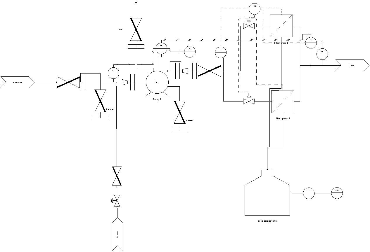
11 P & ID diagram with outline of additions to system
Nomenclature
| Ri | Percentage retained in the sieve with opening size i | % | ki | The permeability of i | m2 |
| WS,i | The mass of solids present in the sieve with opening size i | kg | Lc | The thickness of the filter cake | M |
| WT | The total mass of solids placed at the start in the top sieve screen | kg | Lm | The filter medium thicknes | M |
| Dp | Average particle diameter | µm | kc | thefilter cake permeability | m2 |
| dpavg | The average particle diameter for the solids present in the slurry | µm | km | The filter medium permeability | m2 |
| μ | The viscosity of the liquid phase of the feed and the filtrate | Pa.s | V | The volume of filtrate output from the filter media | m3 |
| pvap | Vapour pressure of liquids in feed | Pa | t | the period of time the filtrate was collected in | s |
| Re | Reynold number for flow through a packed bed | dVdt | The filtration rate | m3 s-1 | |
| ρs | Average density of the dry solids | kg m-3 | Rm | Filter medium’s resistance | m-1 |
| ρl | Average density of the liquids in the slurry | kg m-3 | Rc | Filter cake’s resistance | m-1 |
| dpse | The equivalent spherical diameter | µm | α | Specific cake resistance | mkg-1 |
| εb | The porosity of the bed | W | Mass of the filter cake | kg | |
| ρ | The density of the fluid flowing through the packed bed | kg m-3 | C | The mass of solids per unit volume of filtrate | kgm-3 |
| us | The superficial velocity | m s-1 | αo
and s |
Compressibility constants | mkg-1 and Pa-1 |
| Q | The volumetric flowrate through the bed | m3 s-1 | ∆P | The pressure change the pump has to do to a stream | Pa |
| A | The filtration area | m2 | Qp | The volumetric flowrate into the | m3 s-1 |
| φ | Sphericity | ℵ | The efficiency of the pump | % | |
| ε | Porosity | NPSH | Net positive suction head | m | |
| Vp | The volume of the particle | m3 | ρp | The density of the fluid entering the pump | kg m-3 |
| ∆PTotal | The total pressure drop through the filter unit | Pa | g | Gravity constant | 9.81 m2 s-1 |
| ∆PC | The pressure drop due to the filter cake | Pa | hs | The suction head | m |
| ∆Pm | The pressure drop due to the filter medium | Pa | Pp | The pressure of the fluid entering the pump | Pa |
| ∆Pi | The pressure drop due to flow through i | Pa | tf | Time needed to complete the filtration | s |
| Li | The thickness of i | m | td | The total down time | s |
| Vf | The volume of filter cake that has formed | m3 | n | Expected plant life time | years |
| TAC | Total annual cost | $ | T | The total installed cost (purchase and installation costs together) of the plant items | $ |
| ACC | Annualised capital cost | $ | ∃ | The cost of electricity | $ 0.07 KWh-1 |
| i | Interest rates | % | δ | The hours the plant operates per year | 8200 hours |
| Sv | Sauter particle diameter | µm | Vfilter | Volume of the filter | m3 |
| tcycle period
, |
total time cycle period, | s | x | Number of filter presses |
1 Introduction
1.1 Process Overview


KEY:
| P |
|
| M |
|
| C |
|
| R |
|
Purification
Section section
Main process section
Carbon capture section
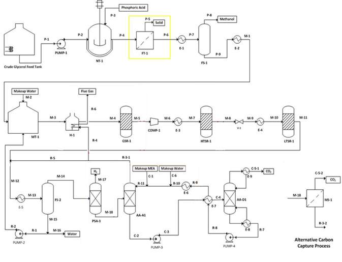
Figure 1. Full process flowsheet outlining report focus
As can be seen in Figure 1, the design project outlines the design of a plant producing hydrogen via the process of converting crude glycerol to hydrogen with the use of glycerol steam reforming. The plant is split into three sections to conclude this task, the purification of crude glycerol from the acids, solids (fats and ash) and methanol present in the crude glycerol; the process of steam reforming the purified glycerol to hydrogen and the final section being the purification of the output hydrogen from the CO and CO2 also produced during the reaction, furthermore in order to improve the environmental sustainability of the process the CO2 is furthermore separated via a carbon capture system, allowing the remaining hydrogen present in the waste output to be used as a fuel for the fired heater and the CO to be further reacted to a less troublesome CO2.
Table 1. Stream to enter the filtration unit.
| P-4 | ||
| Total Mass Flow (kg/h) | 10325.66 | |
| Total Molar Flow (kmol/h) | 196.88 | |
| Temperature (K) | 328.00 | |
| Pressure (kPa) | 181.30 | |
| Vapour Fraction | 0.00 | |
| Component Molar Fraction (%)
|
Glycerol | 32.70 |
| Methanol | 53.40 | |
| Proteins | 0.01 | |
| Triglycerides | 0.32 | |
| Ash | 11.1 | |
| Phosphoric Acid | 0.00 | |
| Phosphate Salts | 2.43 | |
The main objective of the current report is to produce a detailed design of the filtration unit to filter out all the solids present in the stream displayed in Table 1, which are the phosphate salts and the ash. This is of great importance due to the fact that the presence of the ash and phosphate salts in the crude glycerol output from the neutralisation tank reduces the efficiency of the plant via various mechanisms:
- Sedimentation in the pipelines, plant units and heat exchangers causing increased pressure drop and therefore increasing utility costs in terms of pumping costs.
- Coking and deactivation of catalysts via various mechanisms including sintering due to the presence of salts, therefore it is of great importance for the salts present in the feed to be removed as it is of great importance for the reactions throughout the process to have the maximum conversion; as this has a major effect on the plants profitability, also a reduced lifetime for the catalysts will increase costs in terms of repurchasing catalysts and increases downtimes that may occur due to the need to either regenerate the current catalysts or to reinstall new catalysts if the current is beyond the capability to be regenerated.
To conclude this objective the filtration unit equipment selection will be explored and a justification of the final equipment to be used is defined, also all the required theory and equations needed to design the selected filtration unit is to be outlined providing the opportunity for optimisation of the process parameters in terms of minimising the total annual cost for the filtration unit and the required ancillaries, by minimising the operating and annualised capital costs needed due to the unit. A final mass and energy balance is also completed with the optimal parameters determined allowing for a sensitivity study to be undertaken for the filtration unit. Furthermore, with the design specifications found the mechanical engineering design of the filtration unit is to be completed, in conjunction with a specification sheet for the plant item. An exploration and analysis of any safety concerns that may occur is to be completed allowing for a detailed control system and manning requirements to be discussed and determined. With all the previous considerations completed the final estimated capital and operating costs is to be determined.
The original secondary objective of the report was to optimise the glycerol-water recycle stream in regards to purge fraction, however in collaboration with other members of the design group it was found that this will not be required as a lower fraction of methanol will be present in stream M-15 than what was assumed previously.
1.2 Equipment selection
In order to determine the exact equipment unit to conclude the solid-liquid separation of stream P-4 a range of factors are to be analysed including the feeds solid concentration; as various filtration units are in capable of separating a solid greater than a set weight percentage but are extremely excellent and efficient in separating solids that are present in an extremely low concentration and vice versa, the feed liquids vapour pressure is also of great importance as certain filtration equipment are incapable of separating in the presence of vapours. The liquid feed vapour pressure is concluded by creating a liquid feed stream of glycerol and methanol in HYSYS in the concentrations that are present in P4, as well as the same process conditions and extracting the vapour pressure output by HYSYS. The scale of operation is of great importance due to various limitations of scale in an industrial setting for various filtration units. Furthermore, the safety concerns of the slurry to be separating including the fact of whether it is toxic, flammable or explosive is a factor to be analysed.
Table 2.Factors to aid in equipment selection.
| Feed Solids concentration | 9.96% wt |
| Vapour pressure of feed | 59.06 kPa |
| Scale of operation | Feed slurry of 10325.66 kg hr-1 |
| Is the slurry toxic, flammable or explosive? | No |
| Objective of the separation (Solid recovery or clarification of liquid) | Clarification |
With the factors outlined in Table 2 analysed two options are presented to conclude this solid-liquid separation; a rotary vacuum drum filter or a filter press, for which both operate under the scope of cake filtration and allows the separation to occur due to the presence of a pressure differential.
The major difference between a rotary vacuum drum filter and a filter is the fact that the rotary vacuum drum filter is a continuous operation unit whilst the filter press is generally considered a batch unit however with current improvements and advances in technologies automatic plate and press filters have been made for which allows the process to operate as a semi-continuous process [1]. With this factor it is preferable to use the rotary drum filter however due to the presence of phosphate salts which have a relatively large particle diameter which concludes that its highly likely that the specific resistance of the cake will be high, removing the capability to use a rotary vacuum drum filter for this separation [2]. Therefore, it has been decided that for this operation an automatic filter press will be used for this separation.
As stated previously the filter press is an example of cake filtration where in which the solids that are to be separated from the fluid are deposited on the upstream side of the filter medium. This initial first later deposit causes the filtration to occur on the cake that is formed and the filter mediums role is to provide a support for the filter cake and the general filtration process [3].
1.3 Filter press type selection
There are two types of filter presses that may be selected, the plate and frame filter press and the recessed filter press. The plate and frame filter press is constructed from a metal frame that holding multiple filter plates together to develop a pressure chamber. The plates in the plate and frame filter press are covered with the filter medium for which a hollow frame is placed in between each filter plate. For the operation of the plate and frame filter press the slurry to be filtered is fed into the frame for which after filling the plate it begins to filter through the filter medium for which outputs the filtrate. At the end point of the filtration period the filter press is opened and cleaned.
In contrast, the recessed plate filter press is constructed from plates with recesses. These allow the plates to form a hollow space in between them when pushed together which acts in the same manner as the frame in the plate and frame filter press.
Table 3. Advantages and disadvantages of different filter press types.
| Filter press type | Advantages | Disadvantages |
| Plate and frame filter press | -Larger maximum cake thickness of up to 200 mm. | -Greater chance of plugging for which one plate is filled whilst the other is empty, causing a pressure difference between plates to form and in turn damaging the plates.
-Leaking from a plate and frame filter press occurs regularly, causing loss in valuable filtrate. |
| Recessed filter press | -Easier discharge of cakes.
-Plugging will not occur |
-Lower maximum cake thickness of up to 50 mm. |
From an analysis of the above advantages and disadvantages, in Table 3, it has been chosen to use the recessed filter press as it will allow for a greater decrease of operating costs in terms of maintenance of the filter press aswell as a lower chance of unplanned downtime occurring due to the process of plugging. Also the loss of filtrate via leakages with the use of a plate and frame filter press is unpreferrable as it will decrease the profitability of the process.
1.4 Design constraints
The design constraints in place is the fact that filtration unit need to be capable of filtering the stream outlined in Table 1 at the rate and conditions stated in the table. An issue lies in the fact that a majority of the design decisions to be made in designing a filter press is determined via experimentation for which it is highly specific to the feed, filter medium and mode of operation to be used for which constraints exists in the fact that this cannot be done and is outside the parameters of the design project. However, to allow for this design to be made a general overview of the theory and what would be concluded in absence of this constraint is discussed in conjunction with an overview of the assumptions made and equations used to circumvent this constraint and allow progress to the design.
2 Detailed design and optimisation of filtration unit
Due to the nature of the filtration unit and the dependence of design decisions made to be dependent on previous choices; in lieu of producing a detailed design and then concluding optimisation separately for all parts of the design of the filtration unit; at certain stages optimisation of each design choice is to be made in unison and to aid the design decisions made whilst for others the theory and the final design equation derived is explained, including the formulas utilised to calculate costing and a final optimization is to be completed at the end.
As stated previously for certain properties and sections of the design an outlay of what would be conducted in absence of the limitations is described as well as what has been completed instead for that part of the design in order to complete the detailed design of the filtration unit.
2.1 Particle size distribution
Prior to further design it is of great importance to analyse the solids present in the feed and the particle size distributions they possess, as this has an effect on the filter unit type to be designed, the filter medium to be chosen and the cake resistance which in turn is a major component of the filtration unit design. Due to the fact that the particle size distribution is incredibly specific to the solids being filtered and is determined experimentally, via sieve analysis
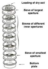 Figure 2.Sieve analyis method. [32]
2.1.1 Particle size distribution analysis experimentally
In order to conclude this process, the solids to be analysed undergoes sieve analysis [4] for which sieve screens of various sized openings are placed on top of each other where in which the one with the largest opening is placed at the top and smallest at the bottom as outlined in Figure 2. With this set-up the dried solids are placed on the top and the sieve screen stack is shaken for a predestined length of time for which at the end of this period the mass of the material retained in each sieve is determined. With the mass in each sieve concluded the percentage retained in the sieve with opening size i,
Riis determined via
| Ri=WS,iWT
|
Equation 1 |
where
WS,iis the mass of solids present in the sieve with opening size i, and
WTis the total mass of solids placed at the start in the top sieve screen, with this process and calculations completed, the particle size distribution may be concluded.
2.1.2 Particle size distribution analysis via assumptions and literature data
Prior to further design due to the lack of capability of employing a sieve analysis, to conclude the particle size distribution of the solids in the slurry, various assumptions are to be made on the solids present in the feed. The triglycerides present in the feed are to be considered mainly composed of the alpha form of stearin for which has a melting point of 327 K therefore will be present as a liquid. Furthermore, the ash present in the crude glycerol is assumed to have similar properties and composition to coal fly ash, as can be seen in Table 4.
Table 4. Assumed composition of ash (composition of coal fly ash). [5]
| SiO2 (wt %) | 60 |
| Al2O3 (wt %) | 20 |
| Fe2O3 (wt %) | 10 |
| CaO(wt %) | 7 |
| LOI(wt %) | 3 |
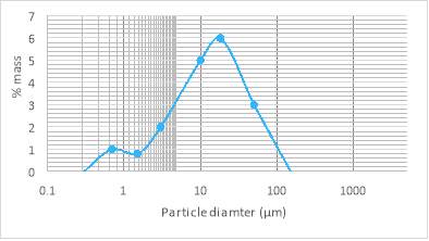
Figure 3. particle size distribution for ash [6].
Figure 3 displays the particle size distribution for coal fly ash which is the assumed to be the same as for the ash present in the process to be designed. From the data it can be found that the average particle diameter,
Dpfor the ash is 14.884 µm.
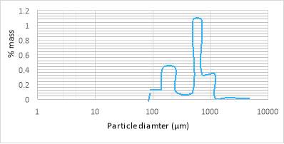
Figure 4.Particle size distribution for Monosodium phosphate [7].
Figure 4 displays the particle size distribution for monosodium phosphate. From the data it can be found that the average particle diameter,
Dpfor the monosodium phosphate is 660 µm.
To determine the average particle diameter for the solids present in the slurry:
| dpavg=∑Dp,i ×Xi
|
Equation 2 |
the sum of the average diameter of component i
, Dp,i, multiplied by the fraction ofi in the solid,
Xi.
For the solids in the feed
dpavgis found to be equal to 380.8725 µm.
2.2 Fixed and known parameters
There are certain parameters which relate to the process that are fixed due to the feed conditions present, for which some are derived via simple calculations of known parameters as per the fact that a mixture of both a solid and a liquid exists therefore properties such as density are a combination of the composite species that are present and are dependent on the percentage of that species present in that phase.
The viscosity of the liquid phase of the feed and the filtrate
μ, as well as
pvap, vapour pressure of liquids in feed and the filtrate for which in both parameters they are assumed to be the same as the composition of the liquid phase of the slurry entering the filtration unit and the composition of the filtrate exiting the filtration unit would be the same, was determined by creating a stream composed of glycerol and methanol with the same conditions and a ratio equal to what exists in the feed stream outlined in Table 1 and extracting the viscosity determined by the simulation for this stream, to give the values given in Table 5.
Table 5. Summary of fixed and known parameters.
| μ | 5.826 Pa.s |
| ρs
, average density of the dry solids |
1090.44 kg m-3 |
| ρl
, average density of the liquids in the slurry |
1581.18 kg m-3 |
| pvap
, vapour pressure of liquids in slurry and filtrate |
59.06 kPa |
2.3 Reynold Number and flow regime
It is of importance to determine the flow regime in which the filtration will occur. Due to the fact that the flow through a filter medium and filter cake is considered to be composite of the flow through a packed bed, to determine the Reynold number for flow through a packed bed
Re[8], it is considered that
| Re=dpseusρμ(1-εb)
|
Equation 3 |
where
μis the viscosity of the filtrate,
dpseis the equivalent spherical diameter,
εbis the porosity of the bed,
ρis the density of the fluid flowing through the packed bed and
usis the superficial velocity which is calculated by
| us=QA | Equation 4 |
where
Qis the volumetric flowrate of liquid through the bed and
Ais the filtration area.
It is assumed that the majority of the solids to be separated (Ash) has a similar sphericity,
φ,and porosity
,ε,to silica sand due to the fact that the major component of the ash, SiO2 (60% of the total mass as can be seen in Table 4) is the component silica sand is made from, therefore similar properties in terms of their particles physical properties is to be expected [9].
In order to determine
dpse, with the fact that
φof the solids to be filtered is assumed to be 0.82 which is most similar to the sphericity of a cube (
~0.806) [10] , the following calculation is to be made
| dpse=(6πVp)0.5
|
Equation 5 |
where
Vpis the volume of the particle to be determined via
| Vp=166dpavg20.806π1/32/3.
|
Equation 6 |
In substitution of values in Equations 3 to 6 and determining
Reis found to be equal to
26.03Am2 for which for a value of an area of greater than 2.6 m2,
Rewill be less than 10 [8] and therefore be in the laminar flow region. A filtration area greater than 2.6 m2 is highly likely in this filtration process and in an industrial scale for which the plant operated under, therefore the flow through the packed bed can assumed to be laminar and further design can proceed accordingly with this assumption in mind.
With the value for
dpsedetermined to be 632.7 µm the
Sv, sauter particle diameter may be determined via the ratio of the volume of a sphere with a diameter
dpsedivided by the surface area of a sphere with diameter
dpse:
| Sv=43×π×(dpse2)3 4×π×(dpse2)2,
|
Equation 7 |
giving a value for the
Svequalling 1.06
×10-4 m.
2.4 Filter Medium
The filter medium function in the filtration process is to provide a support for the filter cake, especially the initial layer that is to form as the majority of the process of solid-liquid separation occurs in the filter cake that forms.
2.4.1 Filter Medium Selection
A major and important element of the filtration unit design is the selection of a filter medium for which the filtration is to occur to be used as the septum. Various conditions are needed for a filter medium to be used including [11]:
- The capability to retain the solids that require filtration and producing a suitably clear filtrate, especially considering the main goal for this filtration process is clarification.
- The filter medium should not blind or plug due to the flow of solids, for which it is what occurs when smaller particulates from the slurry to be filtered blocks and closes the pores of the filter medium, therefore not allowing the liquid to flow through.
- The filter medium should be capable to resist chemically the chemicals present in the slurry and withstand any corrosive effects they may have, as well as the mechanical capability to withstand and to not be damaged or rendered useless due to the process conditions
The most important consideration is the price required to purchase the filter medium including the initial purchase and fitting costs as well as also factoring in the estimated lifetime of a filter medium prior to needing to be repurchased and replaced.
Other factors that required consideration is the level of resistance the filter medium displays to the flow of the filtrate with a lower resistance to flow rate preferable to gain a greater rate of filtration, also the capability and ease of release of the filter cake when cleaning the filter medium is to be accounted, as with lower ability to release the filter cake the time required to clean the filter medium in-between batches of filtration will be greater therefore decreasing production rates.
2.4.2 Selection of optimal filter medium
Prior to the selection of the filter medium to be used various different options that are capable of concluding the desired filtration (have a nominal rating of 0.5 microns or more) were explored and important properties in terms of the filtration to be completed were determined.
Table 6. Table of suitable filter medium’s and their properties [12].
| Filter Medium | Polypropylene | Polyester | Acrylic | Fiberglass | Nomex | Ryton | P-84 | Teflon |
| Max continuous operating temperature (K) | 350 | 408 | 408 | 533 | 464 | 464 | 533 | 533 |
| Chemical compatibility with Methanol | High | High | High | High | High | High | None | High |
| Chemical compatibility with Glycerol | High | High | High | High | High | High | Low | High |
| Chemical compatibility with Minerals | High | Medium | Low | Low | Medium | High | Low | High |
| Resistance to abrasion | High | High | Medium | Low | Medium | Medium | Medium | High |
| Resistance to flow rate of filtrate | Negligible | Negligible | Low | High | Negligible | Negligible | Negligible | Low |
| Cost per square metre ($ m-2) | 1.00 | 1.30 | 4.00 | 10.00 | 12.80 | 15.00 | 17.00 | 20.16 |
Table 6 outlines the various properties to be explored in selecting the optimal filtration medium for which can be seen from the property of max continuous operating temperature that all filter medium is suitable for the process conditions present and are greater than the temperature of the incoming feed of 328 K. The properties exploring the chemical compatibilities and resistance to abrasion are factors determining the lifetime of the filter medium, for which the chemical compatibilities explores the resistance to corrosion and damage from other means to the filter medium due these compounds where in which a high chemical compatibility equates to little to no damage due to the compounds presence, medium equating to slight damage and low equating to significant damage, furthermore the resistance to abrasion explores the resistance to damage via abrasion to the filter medium due to the flow of solids against the filter medium and follows a similar scale to the chemical compatibilities. The resistance to flow rate of filtrate is relevant in the fact that a greater resistance to flow rate reduces the maximum filtration rate capable by the filter medium and therefore production rates, furthermore for a given flow rate a greater resistance produces a greater pressure drop as the fluid flows through the filter medium, which in turn increases costs associated with pumping.
In factoring, the costs associated to each filter medium and the properties of the filter medium outlined in Table 6 as well as other properties not present in the table it is chosen that polypropylene is the optimum filter medium for the filtration to be completed.
In conclusion, polypropylene offers the capability to withstand the process conditions where in which a temperature of 328 K is present because it has a maximum continuous operating temperature of 350K. It offers a high strength and resistance to the chemicals present in the slurry including methanol, glycerol and the phosphate salts, therefore having an improved lifespan in comparison to a majority of the other options. It is also noted that the smoothness of the fibers used to manufacture the polypropylene filter medium, it offers an excellent capability of cake release, therefore easing the cleaning process and reducing the period of time needed to clean the filter medium. The smoothness of the fibers also provides resistance to blinding, which further increases the lifespan of the filter medium. Another major positive of polypropylene is it is negligible and near non-existent moisture absorption of 0.01% [13], therefore reducing the volume of glycerol-methanol filtrate mixture that is lost via absorption on to the medium and increasing productivity.
2.5 Determining specific cake resistance and filter medium resistance
Prior to further calculations the specific cake and filter medium resistance needs to be determined. An issue arises in the fact that filter cake characteristics are affected by and dependent on a variety of factors including the properties of materials present in the slurry (the size, shape and structure of particulates), the operating conditions to be use. Furthermore, the initial stages of the formation of the filter cake is of great importance for in which even the orientation of the initial deposit has an appreciable influence on the structure of the final filter cake and in turn effecting the final specific cake resistance. [14]
In reality the filter medium resistance and cake’s specific resistance is determined experimentally via an underlying understanding of the cake filtration process, however due to the limitations present in this design project the ability to conduct an experiment to determine these values is unavailable and to determine these values theoretically multiple assumptions are needed. However, to outline the process in which the design of a filtration unit is to be conducted in a real design without the limitations currently in present, the underlying theory and methods used to conclude the values experimentally is explored and explained.
2.5.1 Experimentally determining specific cake resistance and filter medium resistance
In cake filtration two resistances are present in series, that due to the filter cake and that of the filter medium; for which at the start of the filtration process the cake resistance is zero due to the fact that no cake has built up and increases continuously as the filtration process progresses. It may be assumed that when modelling cake filtration it is possible to utilise and apply Darcy’s law (in laminar flow through a solid mass, the discharge per unit time is proportional to the hydraulic gradient) [15] for both the filter cake and the filter medium; therefore, concluding that the resistances of both the filter cake and filter medium as well as the pressure drops associated with each one may be added together to determine the sum allowing for
| ∆PTotal=∆PC+∆Pm | Equation 8 |
where in which
∆PTotalis the total pressure drop through the filter unit,
∆PCis the pressure drop due to the filter cake and
∆Pmis the pressure drop due to the filter medium, and in applying Darcy’s law;
| ∆PiLi=μAkiQ
|
Equation 9 |
where
∆Piis the pressure drop due to flow through i,
Liis the thickness of i and
kiis the permeability of i ; to the pressure drops it can be seen that
| ∆PTotal=μLcAkcQ+μLmAkmQ
|
Equation 10 |
where
Lcis the thickness of the filter cake,
Lmis the filter medium thickness ,
kcis thefilter cake permeability,
kmis the filter medium permeability and
Q is determined via
| Q=dVdt
|
Equation 11 |
where in which V is the volume of filtrate output from the filter unit and t is the period of time it was collected in and
dVdtindicates the filtration rate.
The filter medium’s thickness and permeability can be considered to be constant and replaced with a constant denoted as
Rm the filter medium’s resistance, whilst the filter cakes resistance
Rceven though there will be little change in it’s permeability the thickness will increase over time therefore causing
Rcto increase over time;
| Rc=Lckc
|
Equation 12 |
and
| Rm=Lmkm
.
|
Equation 13 |
With the substitution of the resistance terms and Q into Equation 10 and rearranging,
| dtdV=μ∆PTotalARm+Rc.
|
Equation 14 |
Thus with Equation 14 derived a basis for experimentally determining
Rmand
Rcexperimentally is concluded, for which
Rcis also determined to be related to the specific cake resistance,
α, by
| Rc=αW
|
Equation 15 |
where is
Wthe mass of the filter cake.
To determine
Wand relate it to
V,a mass balance of the filtration process is made where in which
| LcA(1-εc)ρs=C(V+εcALc)
|
Equation 16 |
where
C is the mass of solids per unit volume of filtrate, and with the fact and assumption that the volume of liquid retained in the filter is of a much lower value than the volume of filtrate (
εcALc≪V), Equation 12 may be summarized to
| LcA(1-εc)ρs=CV
|
Equation 17 |
for in which
| W=CV.
|
Equation 18 |
With substitution of Equation 13 and 16 into Equation 12 and rearranging the superficial volumetric flowrate,
qis found to be
| q=dVAdt=∆PTotalμRm+αCVA.
|
Equation 19 |
A pilot scale test is then concluded to determine
Rmand
α. However, it is to be noted that an empirical relationship between cake resistance and pressure drop may exists if the filter cake is of an incompressible nature for which
| α=αo(-∆PTotal)s
|
Equation 20 |
where
αoand
sare compressibility constants for the cake which are of an empirical nature to be determined experimentally. However it is to be noted that if
αis found to be independent of
∆PTotal,
swill be zero and the cake is considered incompressible.
A pilot scale filter press is then adopted with a constant pressure operation at various constant pressure drops and a graph of V vs
tVis concluded at each pressure drop, where the y-intercept of the graph
,B,and the gradient
Zallows
αand
Rmto be found as
| B=RmA∆PTotal | Equation 21 |
and
| Z=μαC2∆PTotalA2.
|
Equation 22 |
If
αis found to vary with a change in
∆PTotal, the cake is incompressible and therefore
αoand
swill need to be determined.
2.5.2 Determining specific cake resistance and filter medium resistance theoretically
Even though the filtration process and its theory has been established thoroughly, in the design of a filtration unit it still cannot be accurately determined via a set of basic equations as is possible for a distillation column or a heat exchanger. This issue arises due to conditions that cannot easily be described by a simple and reproducible equation like the unstable nature of particulates and the various precipitates that form filter cakes.
In determining
αthe capillary model in conjunction with the Kozeney-Carman expression for permeability is used to be find
kc[16],
| kc=εcSv2Kz(1-εc)2
|
Equation 23 |
where
Kzis the Kozeny constant which is assumed to be equal to 5 for a fixed bed as is the case of the filter cake that forms.
Therefore with
kcdetermined
αcan be then easily determined by [17]
| α=1ρskc
.
|
Equation 24 |
With Equation 23 and 24 the
αis calculated to equal 6,143,446.52 mkg-1 However, this value does not take into account any compression effects that may occur as well as the migration and movement of fines that are within the filter cake. In addition, the permeability models the particles as rigid structures of fixed geometry where in which each one is in point contact with another; it is also assumed that pressure and liquid drag are the only forces relevant. This may cause issues in the fact that any other force that may be present would have a significant effect especially in the presence of particles of less than 10 pm for which fortunately in this case is not present [18]. With all these considerations of the assumptions made, the real value is determined to be likely an order of magnitude up to an order of two to the estimated value. Therefore, it is recommended if the value determined from Equations 23 and 24 is to be used in design, they be to be multiplied by 50 to determine a deduced specific resistance, providing a value for
αto be 307,172,325.90 mkg-1.
The filter medium resistance is of great difficulty to determine with an equation as it is not only a function of the filter medium but also of the filter cake that forms on top of it and the filtrate to flow through it, however a valid assumption to be made is that
Rmis negligible in comparison to
Rc (
Rc≫Rm). This is because the thickness of the polypropylene filter medium is negligible compared to the thickness of the filter cake and polypropylene has a negligible resistance to the flow of filtrate as outlined in Table 6.
2.6 Modes of operation
The cake filtration equation (Equation 17) in conjunction with the assumptions and determined conclusions from section 2.5.1 gives
| dVdt=A2∆PTotalμαCV.
|
Equation 25 |
Equation 25 contains multiple variables for which three of them are variable and four are constants.
A,
μ,α and Care constant whilst
V,
∆PTotaland
tare variable. In order to solve Equation 25 one of the three variables need to be held constant, for which reflects significantly to the two modes of operations that may occur with the use of a filter press; a constant pressure operation and a constant rate operation.
Both modes of operation are to be explored to allow the capability to choose the optimal mode of operation.
2.6.1 Constant pressure filtration
After the initial cake, has formed on the filter medium the flow through the filter medium and cake generally occurs under a constant pressure differential (
∆PTotalis constant).
Under these conditions Equation 23 is to be rearranged and integrated ;
| ∫0tdt=μαCA2∆PTotal∫0VVdV,
|
Equation 26 |
where in which the limits given is no filtrate volume at zero time and V volume of filtrate after time t, for which the result of the integration is
| t=μαCA2∆PTotalV22
.
|
Equation 27 |
However, an issue with this mode of operation is the fact that as the filtration process progresses and the filter cake thickness increases, the resistance to flow of the filtrate will increase therefore reducing the rate of filtration over time and with the issue in the fact that the filtration rate is fed at a pre-determined rate from part 1 of the design project and a need to output filtrate at a set rate as well this mode of operation is not possible. Although if it was possible to operate at a greater filter rate than what is proposed in part 1 of the design project, an intermediate storage may be placed after the filter unit to allow the rest of the plant to operate at the required rate.
2.6.2 Constant rate operation
To operate under a constant rate, the feed to be filtered is entered into a positive displacement pump prior to entering the filter press. The pump allows the slurry to be delivered to the filter at a uniform volume; for which allows the filtration rate to remain constant throughout. An issue arises in the fact that as the filtration progresses and the cake thickness increases due to cake deposition on the filter medium, the pressure increase delivered by the pump must be increased.
For operation under constant rate,
| dVdt=Vt=Consant
|
Equation 28 |
therefore, in substituting into Equation 23:
| Vt=A2∆PTotalμαCV.
|
Equation 29 |
In this mode of operation, a pump is required prior to the filter press for which as the filter cake resistance increases due to the increasing cake thickness; the pressure to be caused by the pump placed before the filter press increases.
It is to be noted that a greater allowable total pressure drop,
∆PTotal, allows for a greater volume of filtrate to be collected in a given period of time. However, limitations for the process occurs in the fact that the stream to be filtered are at a pressure of 181.3 kPa and the stream that is to exit the filtration unit and enter the heat exchanger E-1, at a pressure of at least 161.8 kPa.
To utilise this fact in conjunction with the pump to be placed before the filtration unit it may be possible to operate at a greater pressure drop but place a pump after the filtration unit to raise it to a pressure of 161.8 kPa that is needed, however in making this choice there are other factors in play such as the maximum allowable cake thickness and the cleaning and wash time of the filter press plates. Also, since a filter press operates under a semi-continuous operation two or more filter presses will be needed to be used as the others are being washed and cleaned and un-operational, to allow for a pseudo-continuous operation via the use of parallel filter presses. An optimization and selection of the options are to be further explored in section 2.10.
2.7 Filter Productivity
To conclude the productivity, the fulltime required to complete a full separation cycle. In addition to the time needed to complete the filtration,
tf, time is also required for the refilling of the filter and the removal and discharge of the filter cake which is placed in a variable called the total down time,
td.
To provide continuous operation from the semi continuous operation of the filter press as stated previously in section 2.6 multiple filter units will be needed and installed, for which it means that the optimal filtration time to be used will equal:
| tf= tdx-1
,
|
Equation 30 |
where x is the total number of filtration units that are to be used, allowing for the process to run continuously at the same rate.
The total time for
tdis estimated to be 30 minutes [19] time required to discharge the filter cake as well as the automated dismantling and refitting of the plates and frames therefore
| td=30 minutes
. |
Equation 31 |
2.7.1 Optimal filtration time and down time period
In working out the optimal filtration time and downtime period the optimum time cycle period is calculated, in essence the optimal thickness of the cake is dependent on the specific resistance of the cake and the total time required to discharge the filter cake. Generally, it can be assumed that utilising a thinner filter cake allows for a greater filtration rate however, it in turn also causes there to be a greater period needed to discharge the cake and refit the plate frame filter press. Even though this isn’t a major issue as it is planned to have multiple filter presses at the same time, there will also be a requirement to optimise in terms of the number of filter presses to use in parallel by factoring in the purchase costs.
With the use of the derived Equation 27 and rearranging:
| tfV=μαCVA2∆PTotal
|
Equation 32 |
and concluding from this that the total filtration time is
| tf=μαCV2A2∆PTotal
.
|
Equation 33 |
the total time cycle period,
tcycle period, for one filtration unit is calculated with the sum of the filtration time
tfand the
tdand in conjunction with Equation 15 it can be seen that this can be calculated with
| tcycle period=μαCV2A2∆PTotal+30 minutes
.
|
Equation 34 |
The overall rate of filtration
Lfor time cycle period is:
| L=Vtcycle period
, |
Equation 35 |
where
Lis at its maximum when
dLdVis equal to zero.
Therefore, when differentiating Equation 35 with respect to V and equating the answer to zero it is gained that
| 0=μαCV2A2∆PTotal+30 minutes-2μαCV2A2∆PTotal
|
Equation 36 |
where in which
| μαCV2A2∆PTotal=30 minutes | Equation 37 |
constitutes that the optimal time to complete the separation and
tfis 30 minutes.
Therefore outlining the optimal
tfis equal to the down time
td.
2.8 Pump design
As outlined in section 2.6 a pump will be required prior to the filtration unit and may also be required after the filtration unit depending on the results of the optimization process. The pump type capable of pumping the required material is to be discussed as well as the to allow for this possibility and the capability to optimize the process successfully an outline of the design and the formula required to produce both pumps is discussed.
2.8.1 Pump type selection
For the pump prior to the filtration unit the capability to pump a solid-liquid mixture without any issue and with a high efficiency is a must. Two types of pump machines are explored, positive-displacement and rotodynamic; for which a rotodynamic pump is chosen due to the multiple advantages [20]:
- Flow through positive-displacement pumps are considered unsteady where in which in the rotodynamic pumps the flow is of a steady nature.
- A majority of positive displacement pumps need a small clearance in between the moving and stationary elements of the pump therefore allowing them to be unsuitable to the handling of fluids that contain solids; in contrast rotodynamic pumps do not have this restriction.
- A safety issue as well as an operation issue caused by positive displacement pumps is in times a discharge is prevented; the pressure within the pump increases causing the pump to be damaged and stop or even cause the casing to burst; in contrast rotodynamic pumps in this situation will continuously rotate the fluid around and the energy applied is converted to heat.
- For a given flow rate there is a tendency for rotodynamic pumps to be of a smaller size and weight than a positive displacement pump
Therefore, in light of the above information a rotodynamic pump for which under this category a centrifugal pump is chosen is to be used for both pumps, after and before the filtration unit.
2.8.2 Pump Design Equations
The major requirement for this design project is to determine the power required by the pump:
| P=Qp∆Pℵ
|
Equation 38 |
Where
∆Pis the pressure change the pump has to do to a stream,
Qpis the volumetric flowrate into the pump and
ℵis the efficiency of the pump that is concluded to be 65% for the pump prior to the unit and 75% for the pump after the filtration unit. The differences in efficiencies is due to the fact that Pump 1 is required to pump a stream of a liquid-solid mixture whilst Pump 2 only pumps a liquid.
It is also of great importance for the design of a centrifugal pump is the availability of the net positive suction head,
NPSH, which is determined by
| NPSH=hs-pvapρpg
,
|
Equation 39 |
where
ρpis the density of the fluid entering the pump,
gis the gravity constant which is 9.81 m2 s-1,
pvapis the vapour pressure and
hsis the suction head which is calculated by
| hs=Ppρpg
,
|
Equation 40 |
where
Ppis the pressure of the fluid entering the pump.
NPSH
is the excess pressure of the fluid above its vapour pressure, where in which if it zero the fluid will be at its boiling point when it enters the pump which in turn may cause evaporation and cavitation which is to be avoided. This concludes that the
NPSHmust be above zero.
Cavitation is to be avoided as the bubbles formed due to this evaporation may collapse causing shockwaves in the pump that will damage the pump.
With the use of Equation 39 and 40 and the fact that it is known that
NPSHmust be greater than zero. The pressure that is to be input to any pump in this system is to be greater than 59.06 kPa, as the temperature throughout the system will not change.
2.9 Capital and operating costs formulas
An important factor of the design of the filtration unit is the minimisation of the total annual cost,
TACwhich is determined via the sum of the operating costs and annualised capital cost,
ACC:
| TAC=ACC+Operating costs
.
|
Equation 41 |
Prior to further continuation the interest rates of the initial loan used to start the plant as well as the assumed and expected plant life time which will be assumed to equal the payback period for the loan that is to be taken. A reasonable assumption for the loan interest rate,
i,is to be taken as 10% whilst the expected plant life time,
n,is to be taken to be 30 years.
With these two values the annualised capital cost ratio
ACCRmay be determined:
| ACCR=i(1+i)n(1+i)n-1
,
|
Equation 42 |
providing a value for the ACCR as 0.106, for which allows for the
ACCto be calculated by
| ACC=ACCR×T
,
|
Equation 43 |
where
Tis the total installed cost (purchase and installation costs together) of the plant items.
To determine the estimated cost of purchase for each plant item a cost correlation is used for which it evaluates the cost of purchase of the equipment in the U.S Gulf coast (which is the location of where the plant is expected to be situated) in January 2010,
Ce.
The following equation
| Ce=a+bSz
,
|
Equation 44 |
coupled with the data in Table 7 is used to determine
Cefor that unit.
Table 7.Cost correlation parameters [21].
| Equipment | Unit for size,
S |
a ($) | b ($) | N |
| Centrifugal Pump | Flow, litres s-1 | 8000 | 240 | 0.9 |
| Filter press | Filtration area, m2 | 128000 | 89000 | 0.5 |
With
Cecalculated, the cost of also installing the equipment is to be factored via a Lang factor,
Lafor which for a mixed fluids solid operating plant is found to have a value assumed to be 3.63, to conclude a value for the installed cost of the equipment,
Ciby:
| Ci=1+LaCe
.
|
Equation 45 |
In order to estimate the current cost of the installed equipment,
Ci,2017, to the latest available CEPCI value for which is for January 2017 it is found that:
| Ci,2017=Ci×CEPCI2017CEPCI2010
.
|
Equation 46 |
Where
CEPCI2010is the CEPCI value for January 2010 which is 532.19 [21] and
CEPCI2017which is the CEPCI value for January 2017 which is 553.03 [22].
The final element to be costed is the operating cost for which in this design is only for the pumps for which is calculated via
| Operating Costs=P×∃×δ
.
|
Equation 47 |
where
δis the hours the plant operates per year which is assumed to be 8200 hours and
∃is the cost of electricity , which is found to be in the area of Louisiana where in which the plant is to be placed for industrial sale to be $0.07 KWh-1 [23].
2.10 Optimisation of filtration unit
The main goal in the optimisation of the filtration unit is the minimisation of the
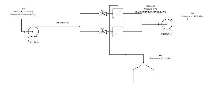
TAC incurred due to the operation of the filtration unit. To minimise this various variable needed to be optimised including the filter area, the filter pressure drop, the maximum filter cake thickness, whether to use pump 2 or not, the number of filter presses to use and the filtration time to operate at. To aid in the understanding of the parameters in question Figure 5 is provided.
Figure 5. Diagram to aid understanding of optimisation parameters.
2.10.1 Degrees of freedom
Prior to optimisation three degrees of freedom are present for which four variables are capable to be used as the degrees of freedom,
A,
Pi,
Poand
Lc. This is because all four variables are considered to be coupled to the other three via one relationship or another.
- A: The filtration area to be used has a major effect on the economics of the plant in terms of operating costs as it also determines the filter cake thickness ,
Lc, where in which the greater the area the lower the filter cake thickness that forms. A lower filter cake thickness will decrease the pressure drop that occurs through the filtration unit and decrease operating costs in terms of pumping. However, it will also increase the cost to purchase the filter press, as it is dependent on the area of the filter press to be purchased.
- Piand
Po: The pressure of the inlet and outlet streams to the filter press are of importance as it will determine the maximum pressure drop that may occur through the unit, and therefore the maximum
Lcthat the filtration unit can allow. Furthermore, dependant on the value for
Poat the end of the filtration cycle, it will decide whether Pump 2 is required or not.
2.10.2 Preliminary optimisation
As stated in section 2.7.1 the optimal
tfis 30 minutes for which from this
Vat the end of one filtration cycle may be calculated to be 4.479 m3 via
| V=Q×tf.
|
Equation 48 |
This in turn allows you to determine the value for
LcAusing a rearranged Equation 17:
| LcA=CV(1-εc)ρs | Equation 49 |
concluding that
LcAfor one complete filtration cycle is equal to 0.000705 m3 furthermore x is determined with a substitution and rearranging of Equation 17 and 18:
|
Equation 50 |
Giving a value for x of 2, therefore two filtration units in parallel is to be used.
In conjunction with the constraint that the maximum possible filter cake thickness,
Lc,max,is 50 mm and the fact that
LcAis equal to 0.000705 m3, the minimum filtration area possible whilst sustaining the
Lc constraint, Aminis calculated by
|
Equation 51 |
giving
Aminto be 0.0141 m2.
2.10.3 Objective function
As part of the optimisation process an objective function needs to be developed for which in this case is the minimisation of
TACthat is determined as in Equation 33.
It is assumed for the purpose of optimisation that the cake thickness is always at its maximum operating thickness and therefore the pressure drop is always at its maximum during the full operation.
As it is optional whether to use pump 2 depending on the conditions a binary value
NP2is used for which if
Pois equal to or greater than
161.8 kPait will equal zero and for any other value it will equal 1.
| Minimise:
TAC=ACCPump 1+NP2ACCPump 2+ACCFilter+Annual Operating costsPump1+ NP2×Annual Operating costsPump2,
|
Equation 52 |
which equates to the objective function for the optimisation.
2.10.4 Optimisation equalities and parameters including constraints
To compute the ACC for the pumps and the operating costs for the pumps the equations from section 2.8.2 and 2.9 are used and the required substitutions are concluded. Furthermore, the filter press ACC is dependent on mainly the area of the filter. The
The relevant substitutions have been made and the equations used for the optimisation process to develop constraints are outlined in Table 8:
Table 8. Optimisation equations.
| Variables to be optimised | |||
| A,
Pi and Po |
|||
| Objective function | |||
| Minimise | TAC=ACCPump 1+NP2ACCPump 2+ACCFilter+Operating costsPump1
+ NP2Operating costsPump2 |
||
| ACCR=i(1+i)n(1+i)n-1 | |||
| ACCPump 1=ACCR × 1+La(apump+bpumpSPump 1zpump)×CEPCI2017CEPCI2010 | |||
| ACCPump 2=ACCR × 1+La(apump+bpumpSPump 2zpump)×CEPCI2017CEPCI2010 | |||
| ACCfilter press=ACCR × 1+La(afilter press+bfilter pressSfilter presszfilter press)×CEPCI2017CEPCI2010 | |||
|
|||
|
|||
| Equality constraints | |||
| Q=A2(Pi-Po)μαCV | |||
| If
Po ≥161.8 kPa then Np2=0 else Np2=1 |
|||
| LcA=0.000705 m3 | |||
| Inequality constraints | |||
| ACCPump 1,ACCPump 2,ACCFilter,Operating costsPump1,Operating costsPump2>0 | |||
| Lc≤50 mm | |||
| Pi> Po | |||
| A≥0.0141 m2 | |||
| Pi, Po>59.06 kPa | |||
| Constants | |||
| Q=Qp,p1=0.00248
m3 s-1 |
|||
| C=0.0996 | |||
| α=
307,172,325.90 mkg-1 |
|||
| Qp,p2
= 0.00233 m3 s-1 |
|||
| μ=
5.826 Pa.s |
|||
| Best Initial guess used | |||
| A= 7 m2 | |||
| Pi=190,000 Pa | |||
| Po=160,000 Pa | |||
Because the objective function is determined to be non-convex (the objective function is non-linear and therefore non-convex as well as the fact that in determining the matrix eigenvalue it was found that it was below zero) and the feasible region is also non-convex (one of the constraints the feasible region is constructed from are non-linear in determining the matrix eigenvalue for the non-linear constraint it was found that it was below zero) any optimisation may yield a local minimum rather than the global minimum and therefore may not provide the real optimal value. To combat this the solver in excel is run multiple times at various combinations of starting guesses for A,
Pi and Poand the optimum solutions output that provides the lowest TAC is decided to be optimal solution for the optimisation.
2.10.5 Optimisation results
The resulting values from the optimisation algorithm have been summarised in Table 9 bellow.
Table 9. Optimisation results.
| Parameters | Values |
| A | 7.054 m2 |
| Pi | 201,728 Pa |
| Po | 161,799.7 Pa |
| Lc | 0.1 mm |
2.10.6 Optimisation results adjustments
As can be seen in Table 9 the
Poit will only be raised slightly from Pump 2 by 0.3 Pa, which can be considered a negligible overall increase especially in the fact that it is a value falls within the range of the error of an average digital manometer (± 0.3 Pa). Furthermore, because the optimisation was completed under the assumption that the filter cake thickness is constant at the thickness it will be at the end of the filter cycle. This assumption in turn means that the pressure drop was also assumed to remain constant throughout operation, however it is known that this value in reality will start at zero at the start of the filtration cycle until it reaches the maximum pressure drop at the end of the filtration cycle due to the increase of the filter cake thickness over time. This in turn means that in reality a majority of the time with these parameters Pump 2 will be non-operational.
To adjust the optimisation result for this fact and to allow for conditions that are more practical
Pois adjusted to 161.8 kPa and therefore from this fact Pump 2 is not to be used. With this adjustment the new values for the end of operation is found to be as displayed in Table 10.
Table 10.Adjusted optimisation results.
| Parameters | Values |
| A | 7.054 m2 |
| Pi | 201728 Pa |
| Po | 161800 Pa |
| Lc | 0.1 mm |
2.11 Mass and Energy Balance
The optimised results for
Poand
Ais used to conclude a mass and energy balance for the filtration unit. However due to the fact that certain major variables change over time as the process continues, a plot of how these values vary over time is completed prior to finalising the mass and energy balance.
2.11.1 Major variables that changes during operation
Prior to completing the full mass and energy balance the change of pressure drop through the filtration unit over time and in turn the value for
Piover time, the volume of filtrate collected,
V,over time and
Lcover time. These are done as these are the only three variables that will vary over time.
To begin and allow the other two aspects to be determined,
Vover time is calculated via Equation 48 where
tfis substituted with the current filtration time and as t will be at a maximum of 30 minutes, which is the value for
tf,
Vis determined from zero seconds to 30 minutes.
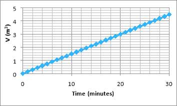
Figure 6. V against time.
As can be seen from the above Figure 6,
Vincreases linearly from 0 to the maximum 4.479 m3 for one filtration cycle period, which is what is expected as per the fact that this filtration unit is to operate at a constant rate. This in turn allows for
∆PTotalover time to be plotted via a rearranged Equation 29:
| V2μαCA2t=∆PTotal
.
|
Equation 53 |
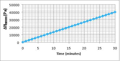
Figure 7.
∆PTotalagainst time.
Figure 7 shows that
∆PTotalincreases linearly from 0 Pa to 39928.25 Pa in one filtration cycle period. This as for the case of
Vagainst time is because of the constant rate operation mode. This allows
Piover time to be determined by the fact
| If ∆PTotal>19500 Pi=∆PTotal+161.8 kPA
Else Pi=181.3 kPA
|
Equation 54 |
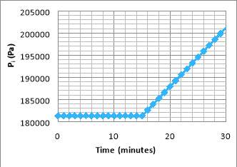
Figure 8.
Piagainst time.
Figure 8 shows that
Piwill remain at 181.3 kPa up to a time of 15 minutes into a filtration time cycle period after which it increase linearly from 181300 Pa to 201728 Pa in one filtration cycle period. This is because the pressure drop caused by the filtration process does not cause the output stream to drop below the pressure of 161.8 kPa for which after this period at 15 minutes it begins to increase linearly because of the constant rate operation mode. Furthermore, it can be seen that it reaches the end pressure that was determined from the optimisation.
The final varying major variable to be plotted as it changes over time is
Lcfor which to calculate it’s change over time, a rearranged Equation 49 is used:
| Lc=CVA(1-εc)ρs | Equation 55 |
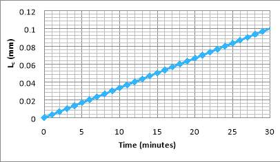
Figure 9.
LcAgainst time.
Figure 9 shows that
Lcincreases linearly from 0 mm to 0.1 mm, the final filter cake thickness determined in the optimisation, in one filtration cycle period.
2.11.2 Mass Balance
A mass balance has been made on the filtration unit providing the capability to determine the flow rates in and out of the filtration units, as well as the compositions of the streams that exit. To complete the mass balance the steady state mass balance equation is used, to produce Table 11:
| ∑inṁ-∑outṁ=0 | Equation 56 |
Table 11. Mass balance of filtration unit.
| P-4 | P-5 | P-6 | ||
| Total Mass Flow (kg/h) | 10325.66 | 1028.44 | 9296.22 | |
| Total Molar Flow (kmol/h) | 196.88 | 26.72 | 170.16 | |
| Volumetric flow rate (m3/h) | 10.00 | 1.04 | 8.96 | |
| Temperature (K) | 328.00 | 328.00 | 328.00 | |
| Pressure (kPa) | 181.30 | 181.30 – 161.80 | 181.30 – 161.80 | |
| Vapour Fraction | 0.00 | 0.00 | 0.00 | |
| Component Molar Fraction (%)
|
Glycerol | 32.70 | 0.00 | 37.83 |
| Methanol | 53.40 | 0.00 | 61.78 | |
| Proteins | 0.01 | 0.00 | 0.01 | |
| Triglycerides | 0.32 | 0.00 | 0.37 | |
| Ash | 11.1 | 81.80 | 0.00 | |
| Monosodium Phosphate | 2.43 | 18.20 | 0.00 | |
2.11.3 Energy Balance
Due to the fact that the pressure increase caused by Pump 1 will increase over time, to allow for the electricity requirements for the total period to be calculated the average value for
Pi,
Pi,avg,is determined via Figure 8. Thus giving a value of 193649.2 Pa for
Pi,avg 1. This in turn allows
∆PPump 1, avg 1 cycle, the pressure rise Pump 1 needs to provide to be determined by
| ∆PPump 1, avg= Pi,avg -181.3 kPA,
|
Equation 57 |
giving a value for
∆PPump 1, avgof 12349.2 Pa.
Thus allowing
PPump 1,avg, the average power required by Pump 1 to be calculated via Equation 38 to be equal to 22.297 kW.
2.12 Summary of operating parameters
A summary of fixed operating parameters are outlined below in Table 12, whilst any parameter that varies over time is given within the range it operates between.
Table 12.Summary of operating parameters.
| Parameters | Values |
| A | 7.054 m2 |
| tf | 30 minutes |
| ∆PPump 1 | 0 to 19,928.25 Pa |
| ∆PPump 1, avg | 12349.2 Pa |
| PPump 1 | 0 to 35.98 kW |
| PPump 1,avg | 22.297 kW |
3 Assumptions made during detailed design and optimisation
A range of assumptions have been required to complete the detailed design and optimisation of the filtration unit, some due to limitations and constraints in what may be done related to the design process (experimentation to determine process related constants and conditions) and others are due to the limitations in theoretical design of a unit for which the only way to know these values and conditions is to actually create and run the process at its full scale, therefore allowances and contingencies are made to accommodate. The full range of assumptions that have been required have been outlined in Table 13 below.
Table 13. Assumption made during detailed design and optimisation.
| Section | Assumption | Justification |
| Preliminary Assumptions
|
Specific cake resistance will be relatively high therefore use filter press | Due to presence of phosphate salts (Monosodium phosphate) and the fact that it has a large average particle diameter for which specific cake resistance is proportional to the particle diameter of the solids the cake is to be composed of. |
| Triglyceride is liquid. | The triglycerides present in the feed are to be considered mainly composed of the alpha form of stearin for which has a melting point of 327 K and therefore will a liquid. It was assumed to be mainly composed to allow the design to progress in absence of the information of the exact triglyceride types present in the crude glycerol, and due to the fact that all triglycerides have similar molecular weights (
~ 892 kg kmol-1). |
|
| Protein is considered a negligible quantity. | Protein does not require separation as It has no negative effects on the glycerol steam reforming process in terms of conversion and yield, furthermore it is present in extremely low quantities at a mole fraction of 0.0001 from all the solids that enter are present in stream P-4, which considering the scale of the operation to be used is negligible. Another matter is the fact that proteins have sizes that are within the ranges of nanometres therefore will incur greater costs in separating them with no benefit. | |
| 3.1 Particle size distribution | Ash has similar properties as coal fly ash | This is a good assumption to make as generally all ash types have similar properties and in absence of the ability to analyse the ash particle size distribution via sieve analysis method and the available of data on coal fly ash this is a valid option. |
| 3.2 Fixed and known parameters | Properties of slurry and filtrate liquid will be the same. | It is assumed that both methanol and glycerol are similarly retained in the cake, as well as the fact there is no change in temperature for the filtrate when entering and exiting the filter press. |
| 3.3 Reynold Number and flow regime
|
Particles of solids in the slurry and the cake have a similar sphericity (0.82) and porosity (0.42) to silica sand. | A major proportion of the solids is ash and furthermore a major component of the ash is SiO2 (60% of the total mass) which is also what silica sand is made from, therefore it can be assumed the particles for both will have similar properties in terms of particle and bed properties. |
| Sphericity of particles is similar to that of a cube particle | The sphericity of 0.82 is most similar to the sphericity of a cube (
~0.806) which is the available equation to be able to determine the dpse, furthermore due to small scale of the particles (diameters in the µm) this slight error will have little to no effects on further calculations and allows the design process to progress. |
|
| Flow is laminar | Re
is found to be equal to 26.03Am2 for which for a value of an area of greater than 2.6 m2, Rewill be less than 10 and therefore be in the laminar flow region. A filtration area greater than 2.6 m2 is highly likely in this filtration process and in an industrial scale for which the plant is operated under |
|
| 3.5 Determining specific cake resistance and filter medium resistance | Darcy’s law: to use this equation it is assumed that the filter cake and medium is saturated and the flow is laminar | Throughout the filtration process the cake and medium will be submerged in liquid and as determined in section 2.3. the flow is likely to be laminar. |
| Kz
is equal to 5 |
This is the estimated value for a fixed or slow moving bed for which the filter cake is to not be fluidized when formed therefore this assumption holds true. | |
| Filter cake is incompressible and that pressure and liquid drag are the only forces relevant | Although it is highly unlikely to be true, it is difficult to determine the value for
αtheoretically without these assumption and furthermore adjustments are made to the calculated value to account for the errors this assumption causes as well as various other elements that have not been accounted for by the equations |
|
| Calculated value is around 1/50th the value of the real value | This assumption is made to account for any errors caused by the assumptions present in the equations used to determine
αtheoretically and factors in any migration and movement of fines that are within the filter cake as well as compressibility factors. |
|
| Filter medium resistance is negligible | The thickness of the polypropylene filter medium is negligible compared to the thickness of the filter cake and polypropylene has a negligible resistance to the flow of filtrate as outlined in Table 1. | |
| 3.7 Pump design | Efficiency of pump to be place before the filtration unit is 65% and after is 75% | This assumption is made with the use of a pump performance curve in which reasonable estimates are made to conclude these efficiencies from the plots. |
| 3.10 Optimisation of filtration unit | The cake thickness is always at its maximum operating thickness and therefore the pressure drop is always at its maximum during the full operation. | This assumption has been made to allow the optimisation to be completed via an objective function and constraints. Also it is an assumption that is capable of providing the actual optimum operating parameters as for each combination of operating conditions the parameters the actual TAC will be of equal proportion to the estimated TAC concluded through the optimisation process. |
3.1 Management of solids output assumptions
During the filtration process a filter cake composed of a solid of ash and monosodium phosphate is formed and discharged. Currently it is assumed that this discharged solid is to be stored for which then it will be disposed of. An issue in the disposal of the solids is the fact that fly ash may contain quantities of heavy metals and other toxic materials which are capable of contaminating local ground and surface water supplies over time. Although in the U.S ash is classified by the Environmental protection agency (EPA) as non-hazardous waste [24], it is of importance to dispose and contain the disposed ash in a safe manner that will not allow for the contamination that it may cause to occur therefore coal ash disposal rules have been implemented. Due to this the solids will need to be disposed in a specified coal ash surface impoundment or landfill for which the coal ash disposal rule aids to protect the negative effects of contamination by regulations including the monitoring of groundwater nearby and the requirements impoundments and landfills to not be located near drinking water supplies.
Although it is assumed that the ash and monosodium phosphate, up to this point of the design project, is a waste product it may be converted to two useful by-products in which the ash may be utilised in the manufacturing of concrete as well as the making of wall boards. Furthermore, monosodium phosphate may be used for the treatment of food and water and an emulsifier for various products including toothpaste. Therefore, if a separation is concluding on the solid waste product such as mechanical screening which may be possible in the fact that both have very different particle diameters and in turn will allow for the process gross margins to increase.
4 Final estimated costing
In determining the final estimated costing the estimated TAC is to be calculated for which to incorporate all costs
| TAC=ACCPump 1+ACCFilter press+Annual Operating costsPump1
+ Annual Operating costsFilter press,
|
Equation 58 |
is to be calculated.
4.1 ACC for units
The ACC for the units have been determined via the equations in section 2.9, to produce Table 14.
Table 14. ACC for units.
| Determining of ACC for Units | ||||
| i | 10% | |||
| n | 30 years | |||
| ACCR | 0.106 | |||
| Purchase cost
(US$ Jan 2010) |
Installed cost
(US$ Jan 2010) |
Installed cost
(US$ Jan 2017) |
ACC
(US$ yr-1) |
|
| Two filter presses | 492,378.06 | 2,279,710.41 | 2,368,981.47 | 251,299.77 |
| Pump 1 | 1402.35 | 6492.90 | 6747.15 | 715.73 |
| Total | 258,046.92 | |||
4.2 Annual Operating costs
There are two types of operating costs for the units, those associated with the operation of Pump 1 and the operating costs required for the filter presses.
4.2.1 Pump 1 annual operating costs
To determine the annual operating costs for Pump 1
PPump 1,avgthat was determined previously to be 22.297 kW needs to be converted to the annual operating cost for Pump 1 by
| Operating Costs for P1=PPump 1,avg×$ 0.07 KWh-1×8200 hrs
|
Equation 59 |
to give a value of $12,798.48 year-1 for the operating costs of Pump 1.
4.2.2 Filter press operating costs
There are two main operating costs related to the filter press, the purchase and refitting of new filter medium and the water required for the cake discharge and plate cleaning process.
As in Table 6 the purchase cost of the polypropylene filter cloth is $1 m-2 and therefore for the required filtration area of 7.054 m2, the cost of the filter cloth will be $ 14.10 for both filtration units, however as per the fact that the filtration medium only needs to be changed every one and a half year to find the annual cost of purchase for the filtration medium
| Annual cost of purchase for the filtration medium=$ 14.10×23=$9.40 per year.
|
Equation 60 |
Furthermore, to complete the washing of the filtration medium wash water is required for which is 15% of the filtrate that has been collected. There are two main sources for this water, it may be obtained from a supplier of self-supplied. Due to the location of the plant in Louisiana and the large sources of fresh water that may be obtained from a nearby lake or from ground water, this is considered to have no costs. This reasoning is further proven in the fact that 88% of all industrial water used in the USA was determined to be self-supplied in 1995 [25].
4.3 Summary of final estimated costing
It can be seen from Table 15 that the annualised capital costs in terms of repayment provides the majority of the costs related to the filtration unit system, owing for over 95% of the total annualised cost. This is due to the fact that two filter presses were required to allow for a pseudo-continuous operation, which therefore increased the initial capital outlay to purchase and install the equipment.
Table 15. Summary of costing.
| Annualised Capital Cost Summary | |
| Total ACC (US$ yr-1) | 258,046 |
| Operating Cost Summary | |
| Annual operating costs for filter press (US$ yr-1) | 9.40 |
| Annual operating cost for Pump 1(US$ yr-1) | 12,798.48 |
| Total annual operating costs (US$ yr-1) | 12,807.88 |
| Overall Economic summary | |
| Total ACC (US$ yr-1) | 258,046.92 |
| Total annual operating costs (US$ yr-1) | 12,807.88 |
| Total annualised costs (US$ yr-1) | 270,854.81 |
5 Mechanical Engineering design
Two types of filter press mechanical machine designs are available for a recessed plate filter press. For which the main and major parts are the closing device and the plates. Another major consideration for the mechanical design of the filter press is the total volume needed for the filter press.
5.1 Closing device
There are two options for the closing device to be used for the closing device, a side-bar design and an overhead beam design. Each offers its own advantages dependent on the requirements of the filtration and the general process specifications.
The first design is a side-bar design for which the plates are pushed together via a piston to the side of the plates to push them closed together and then in the cake discharge section of the filtration cycle it pulls them apart open to allow for the cake to be released.
An overhead beam design is a design of an overhead suspension of the filter plates that in a comparable manner to side-bar design the overhead beam incorporates a motor that pulls the plates together and apart dependent on the cycle.
To select the closing device an analysis of the advantages of both are outlined in Tale 16.
Table 16.Comparison of closing devices.
| Closing Device | Advantages |
| Side-bar design | -Greater ease in automating operation of filter press
-Lower land area required for filter press. |
| Overhead beam design | -Easier access to plates for maintenance
-Allows for extremely corrosive materials to be filtered -Allows for extremely high operating pressures |
It is decided to use the side-bar design as the operating conditions of the filter press in terms of pressure are not extremely high, and although methanol is considered to be corrosive, the side-bar design is capable of being built from stainless steel which decreases it’s effect significantly and allowing it to be a none-issue. The main reason the side-bar design is used is chosen is to allow for the automation of the filter press, which is a significant priority for the filter press.
5.2 Plates
It has already been chosen to use recessed plates, however what remains to be chosen is the number of plates and the area of each plate however prior to the completion of the mechanical engineering design, it is firstly of importance to determine the required volume for the filter press.
It is firstly of importance to determine the volume of the solids deposited per filtration cycle,
Vsby
|
|
Equation 61 |
concluding that
Vsis equal to 0.446108 kg. After determining
Vs, the required volume of the filter,
Vfilteris calculated by
| Vf=Vs(1-εc)
,
|
Equation 62 |
to be equal to 0.797 m3.
With the filtration, area selected the necessities needed to provide this is chosen by the selection of a specific plate size and number of plates for which the filtration area required is spread over each plate. In order to minimise costs a combination of various plate sizes and numbers may be analysed to determine the optimum combination to be used for the filtration area needed. To aid in this endeavour data collected for optimal plate size,
R, and number in relation to filtration area required is plotted in Figure X below.
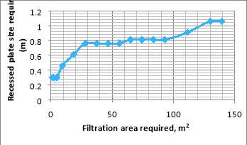
Figure 10. Required filtration area vs recommended Recessed plate size. [2]
To allow for calculations to be made a trend line is determined for the data plotted for which the polynomial equation with an R-squared value of 0.9882 is found:
| R=-2×10⁻³×A6 -2×10-11×A5+7×10⁻⁹×A4+2×10⁻⁶×A3 -0.0004×A2 + 0.0277×A + 0.2372
.
|
Equation 63 |
Substituting the determined value of
A(7.054 m2) into Equation 63 gives
Rto be0.38 m in the diagonal.
Furthermore to find the optimal number of plates to use,
O, the data collected for optimal number of plates to use in relation to filtration area is plotted below in Figure 11.
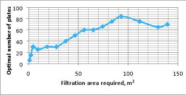
Figure 11. Required Filtration area vs iotumum number of plates. [2]
Similarly, to allow for calculations to be made a trend line is determined for the data plotted for which the polynomial equation with an R-squared value of 0.9655 is found:
| O=-2×10⁻³×A6+1×10⁻⁷×A5-3×10⁻⁵×A4+0.0026×A3 -0.1096×A2 + 2.4713×A + 10.203
.
|
Equation 64 |
In a similar fashion substitution
Agives
Oto be 27.4 which may be rounded down to 27.
5.3 Dimensions of filter press and summary of mechanical design
With the number of plates, plate size and required volume of filtration determined, these measurements need to be compared with recessed filter press suppliers numbers as the measurements for distances A, B, C, D, E and F (in figure 12 below) are dependent on the supplier. However for the recessed filter press supplied by SERFILCO the measurements for a recessed filter press that required a filtration volume within the range of 0.708 m3 and 1.416 m3 which the required filtration volume for the filter press design fits within this range, is provided in Table 17.
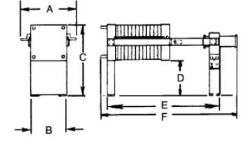
Figure 12. Dimensions for recessed filter press. [26]
It is to be remembered that the values determined via Equations 62 and 63 are general guidelines and recommendations and provide a starting point for determining the plate number and plate area that is to be used and to find the actual optimum plate number and area to use multiple suppliers need to be contacted and a comparison of the prices they provide is to be made. With the estimated values for
Rand
O , adjustments are made to fit the required filtration area for the process and the results of the adjustments are given in Table 17 below
Table 17. Dimensions for recessed filter press. [26]
| Dimension /Measurement | Estimated measurement (m) |
| A | 1.68 |
| B | 1.47 |
| C | 2.18 |
| D | 0.89 |
| E | 3.58 |
| F | 1.75 |
| Plate number | 26 |
| Plate size (m) | 0.384 |
6 Specification sheets
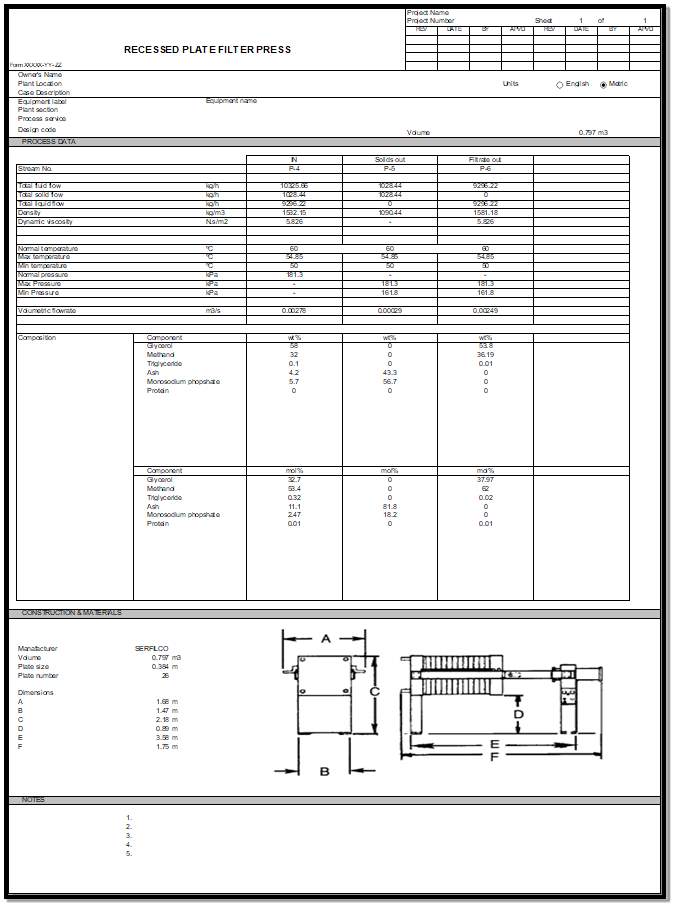
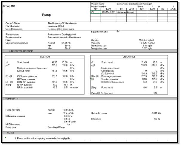
Figure 14.Pump Specification sheet.
Figure 13. Filter press specification sheet.
7 Sensitivity studies
To determine the response of the system to possible changes in conditions a sensitivity analysis was concluded on the system. Three important variables potentially may vary during operation
Aand
C.
7.1.1 Variations in filtration area
Although with the use of polypropylene as the filtration medium, the opportunity for blinding and plugging of the filter medium, in turn reducing the useable filtration area, is minimised, it may still occur. Another issue that may cause a reduction in useable filtration area is due to the possibility of uneven filtration cake distribution on the filter plates. The main effect this is to cause the process is increasing the filter cake thickness needed and therefore increasing the pressure drop that occurs and the pumping requirements of Pump 1. This will of course cause the utility costs to increase, as can be seen in Figure 15.
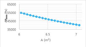
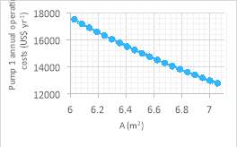
Figure 15. Graphs outline change in maximum pressure drop and annual operating costs with change in filtration area.
7.1.2 Changes in solid fraction in feed
A change in the solid fraction is to occur due to the possible variations in batches and types of crude glycerol to be used in the process, especially due to the fact that the crude glycerol is mainly a by-product of biodiesel production. The composition of the crude glycerol from the production of biodiesel is further dependent on the biomass used to produce it and the general process conditions present, this in turn could allow the solid fraction in the crude glycerol to be slightly greater or slightly lower. A greater solid fraction will mean that a greater degree of separation is needed, for which for if the filtration unit designed is to be used, a greater filtration cake thickness will be gained. This will produce similar outcomes to what was discussed in section 7.1.1 in what would occur for an increased filter cake thickness, as shown in Figure 16.
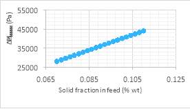
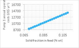
Figure 16.GRAPHS OUTLINE CHANGE IN MAXIMUM PRESSURE DROP AND ANNUAL OPERATING COSTS WITH CHANGE IN solid fraction in the feed.
8 Control systems and manning requirements
Outlining and producing a control system for a process is of immense importance to a plant as it provides various important benefits that aid in automating the plant. For one it provides the ability to quickly respond to any disturbances or variations in process conditions that may affect the operation of a unit and return them to the optimal value providing the needs of downstream units. Furthermore, a successful control system provides the opportunity to have an automated safety system which is capable of automatically adjusting any process conditions that are tending towards unsafe operations. It also allows the opportunity to implement alarms that are triggered to alert operators and plant personnel to rectify the situation quickly before the situation reaches critical conditions. Furthermore, if there is any change in production demands including change in the feedstock used and the production rate a good control system will aid in automating this process and ensuring this transition allows the system to continue to operate in a stable manner.
To allow a full analysis of the required control systems to be implemented a safety analysis, sensitivity studies and analysis of requirements to change production rate is completed, as well as an outline on the control elements needed for the control system needed.
8.1 Operation Control system design
To design a control system to ensure the system operates at optimum conditions and incorporating the ability to accommodate changes in production rate and feedstock all input and output variables are to be identified and in turn all inputs are to be classified as disturbances or manipulated variables.
Prior to a design of any control system it is of importance to know the required number of control loops, to be used for the process control system, needed for the filtration unit section of the plant. The method to conclude this is to determine the number of degrees of freedom for the system for which this will equate to the number of control loops required. It is determined that there are two degrees of freedom for the final designed system, the first being the power supplied to Pump 1 and in turn the pressure increase supplied by the Pump 1 to the inlet stream,
∆PPump 1,and the second being whether filtration unit 1 is being used or filtration unit 2 which is controlled by two control valves that are opened or closed depending on which filtration unit is being used.
For the first control system the final control element is identified to be Pump 1 for which as stated the power input the pump is varied. This is done to conclude a constant flowrate operation that is required. In terms of input variables in this system the input variables are identified to be
Lc, the flowrate into Pump 1 and in turn into the filtration unit,
Piand
Poas well as the pressure of the stream entering Pump 1. The controller will be a multiple input single output (MISO) controller due to the fact multiple inputs for which the readings for them are determined via sensors minus
Lcwhich will need a factor of inferential control as it is to be inferred via readings from other available measurements. The signals from the measurements devices to the controller will be pneumatic as methanol is explosive and to minimise this risk an electrical signal is avoided as much as possible.
For the second controller because the filtration system utilises two filter presses for which one operates as the other is being cleaned, with the use of the flow rate meter on the exit and entrance of the filtration units
Vmay be found for which at a calculated value depending on production rate requirements, feed stock and process condition, the controller will close the currently open control valve whilst opening the currently closed control valve, with this the controller will change the flow of stream P-4 to enter the other filter press and set the one that was last in operation to begin the cleaning and cake discharge process. In contract this controller is a form of a multiple input multiple output controller (MIMO) as multiple measurements and inputs are taken to conclude the actions required for multiple actions including opening and closing both valves and the setting the filter presses to begin the cleaning and discharge cycle or to begin the filtration cycle.
It is of note that the control valves to be used require an actuator to be able to respond to the signal sent from the controller. Of importance in the design of the valves is to implement a fail-safe in which if the signal to the controller is lost the valve will fix itself to a positon of either being open, closed or to remain locked in its last position. As it is preferable for if the control signal to the valves are lost for there to be no flow to the filtration units as if the unit is being cleaned or if it is not it may cause the filtration unit to overfill and cause the plates to blow due to the pressure and in both cases it will cause a leakage and spill of the feed. This is an issue as the feed contains methanol which will create an unsafe environment in the fact that it is toxic to be inhaled or touched. Therefore, with this fact the valves are to fail closed.
For both controllers the controller takes measurements from the disturbances to the system and the control variable, implementing both a feedback and feedforward control in them, creating a feedback/feedforward control system. Furthermore, due to the fact that both controllers utilise multiple inputs model predictive control is to be used.
8.2 Sensitivity studies and relationship to control system
The sensitivity studies completed further promotes the case for the use of model predictive control due to its capabilities to utilise a process model developed for the system that outlines the interactions between the variables to aid it to automatically determine the optimal action to make to produce optimal results. Therefore, this fact allows for the variations that may occur as outlined in the sensitivity studies to not be able to effect the plant’s operations in a major manner.
Another outcome that the sensitivity study has outlined that issues that may arise that may cause a decrease in effective filtration area may cause significant effects to the effectiveness of the general system. In order to combat this, it is proposed to utilise the flow meter placed after the filtration units to create an alarm system that will signal to operates when there is a significant decrease in the flow which may be caused by the damage of a plate that may decrease the filtration area or if significant plugging or blinding has occurred to the filtration area, allowing plant operators to rectify the situation.
8.3 Safety analysis
It is an essential requirement to analyse the safety aspects of all elements of the design project in order to ensure that the final process plant designed will operate in a safe nature; this is also of essential importance to the detailed design of process units for which in this case is the filtration unit. An important element of the safety of the unit is the materials present in the streams entering and exiting the unit as well as inside the unit, the process conditions and general deviations that may occur in process conditions that may cause problems. This will allow for a control system to minimise these issues and control them to be determined and a safety instrumented system to be developed that is to be made as an independent system of the control system to allow for greater contingencies for safe operation, in conjunction with safety devices and operation practices to be placed on the system.
8.3.1 Material safety assessment
There are five compounds and mixtures that are present in the feed and output of the filtration unit including the discharged filter cake: glycerol, methanol, ash, proteins and Monosodium Phosphate.
A condensed COSHH assessment is outlined in Table 18 below, outlining the safety issues caused by the material and the safety measures related to the filtration unit and possible control elements that may be implemented as part of the control system to counter this hazard.
Table 18. COndensed Coshh of materials present in system [27] [28] [29] [30] [31].
| Explosive | Flammable | Toxic
|
Corrosive
|
Safety devices and operation | safety instrumented system | |
| Glycerol | No | No | At temperatures above 290 °C due to the fact that it decomposes to acroelin which is considered to be highly toxic | No | Toxicity is a non-issue as the process conditions of the filtration unit is operating a temperature of 54.85 °C which is much lower than the decomposition temperature of 290 °C. | None |
| Triglyceride | No | No | No | No | None | None |
| Methanol | Yes, flammability limits 6.7% to 36% | Yes, autoignition temperature of 455 °C | May cause extremely serious irreversible effects via inhalation, skin contact and swallowing.
Causes severe pain and burining. |
No | Static discharges may cause ignition therefore the filtration unit is to be grounded.
The filtration unit and surrounding area is to be well ventilated to avoid ignition. Requirement for a nitrogen gas purging system for maintenance. |
None |
| Monosodium Phosphate | No | No | No | No | None | None |
| Protein | No | No | No | No | None | None |
| Ash | No | No | No | No | None | None |
Although a majority of the material is considered safe, they will still need to be handled in accordance with good occupational hygiene and safety practices.
8.3.2 HAZOP of system
A HAZOP is an excellent tool in determining possible issues that may arise with process units due to deviations in process conditions from what is expected, as well as determining a plan of action to counter the deviations that may occur for which are split into non-control related and control related. A HAZOP of Pump 1 is concluded in Table 19.
Table 19. HazOp of system.
| Deviation | Causes | Consequences | Actions | |
| Safety related | Control system related | |||
| High Pressure
(to note although the occurrence is minimised, in the case of the pump, by the use of a rotodynamic pump it may be still possible) |
|
|
|
|
| Low Pressure |
|
|
|
|
| High Temperature |
|
|
|
|
8.4 Manning requirements
The manning requirements suggested for this unit is one personnel ensuring the filtration system operates correctly and to maintain and rectify any issues as well as one person in the control room to monitor the operation of the filtration system. However it is of note that in regards to a whole plant the personnel who are required to complete these tasks may be responsible for multiple units of the plant, therefore when the filtration system is placed in relation to the full plant, less operators and control room staff is required than the sum of all that was predicted for each unit.
9 Conclusion
It is concluded that a detailed design in terms of mechanical and chemical engineering design for a filtration system in the purification section of a glycerol steam reforming plant has been determined. This has been completed via optimisation algorithms and correlations developed to allow the optimum operating variables to be selected. Furthermore, to allow the process to operate successfully and efficiently, a robust control system has been created, including a safety instrumented system separate to it.
However it is noted that the solids separated that have been assumed to be a waste products may undergo further separation to produce valuable by-products that may be sold.
10 References
| [1] | K. SUTHERLAND, Filters and Filtration Handbook (5th edition), Elsevier, 2008. |
| [2] | A. Rushton, Solid-liquid Filtration and Separation Technology, John Wiley and Sons Ltd, 2000. |
| [3] | H. R., Fundamentals of Particle Technology, Midland Information Technology and, 2002. |
| [4] | W. P. /. E. Gregorová, “Characterization of particles,” 2007. |
| [5] | R. Snellings, M. G. and E. J., “Supplementary cementitious materials,” Reviews in Mineralogy and Geochemistry, 2012. |
| [6] | S. O. BADA, “Evaluation and Treatment of Coal Fly Ash for Adsorption Application,” Academic Direct. |
| [7] | T. P. &. G. COMPANY, “Fat composition containing salt, lecithin and hydrophilic silica”. Patent EP0063835 B1. |
| [8] | Neutrium, “PACKED BED REYNOLDS NUMBER,” [Online]. Available: https://neutrium.net/fluid_flow/packed-bed-reynolds-number/. [Accessed 14 March 2017]. |
| [9] | A. P. B. A. Kocamemi, “CHAPTER: 12, Filtration,” Marmara University. |
| [10] | H. Wadell, “Volume, Shape and Roundness of Quartz Particles,” Journal of Geology, 1935. |
| [11] | C. J. &. R. J.F, Chemical Engineering Volume 2, 5th ed, ButterworthHeinmann, 2002. |
| [12] | SLY INC, “CHEMICAL COMPATIBILITY OF FABRICS WITH COMMON CHEMICALS”. |
| [13] | Omnexus, “Water Absorption,” [Online]. Available: http://omnexus.specialchem.com/polymer-properties/properties/water-absorption-24-hours. [Accessed 19 March 2017]. |
| [14] | Svarovsky L., Solid-Liquid Separation, Butterworth and Heinemann, 2000. |
| [15] | C. Tien, Introduction to Cake Filtration, 2006. |
| [16] | T. S. KHEAN, “STUDIES IN FILTER CAKE CHARACTERISATION,” 2003. |
| [17] | J. C. S. P. H. Warren L. McCabe, Unit Operations of Chemical, McGraw-Hill, 2005. |
| [18] | M. Xie, “The fractal model of specific resistance of filtration,” International Conference on Intelligent System Design and Engineering Application, 2010. |
| [19] | K. Sutherland, Filters and Filtration Handbook, 2008. |
| [20] | J. A. S. Richard Turton, Chemical Process Equipment Design, 2017. |
| [21] | K. R. Sinnott, Chemical Engineering Design, Elsevier, 2012. |
| [22] | Chemical Engineerin, “chemengonline.com,” 2017. [Online]. Available: chemengonline.com. [Accessed 20 March 2017]. |
| [23] | Electricity Local, “Electricity Local,” [Online]. Available: http://www.electricitylocal.com/states/louisiana/. [Accessed 20 March 2017]. |
| [24] | EPA, “Coal Ash (Coal Combustion Residuals, or CCR),” [Online]. Available: https://www.epa.gov/coalash. [Accessed 2017 March 23]. |
| [25] | USGS, “Industrial water use,” [Online]. Available: https://water.usgs.gov/edu/wuin.html. [Accessed 25 March 2017]. |
| [26] | sat-eng.com, “RECESSED PLATE,” [Online]. Available: http://www.sat-eng.com/SerfilcoBulletins/F-705.pdf. [Accessed 20 March 2017]. |
| [27] | Quality Ash Association, “COSHH – Safety Data Sheet for PFA/Fly Ash”. |
| [28] | ReAgent, “GLYCEROL TECH MSDS”. |
| [29] | Cayman, “Safety data sheet- trigylceride”. |
| [30] | Innophos, “Monosodium Phosphate”. |
| [31] | SIGMA-ALDRICH, “Methanol”. |
| [32] | Tankonyvtar, “Particle size distribution of soils,” [Online]. Available: http://www.tankonyvtar.hu/hu/tartalom/tamop425/0033_SCORM_MFKHT6504SI-EN/sco_01_02.scorm. [Accessed 14 March 2017]. |
Cite This Work
To export a reference to this article please select a referencing stye below:
Related Services
View allRelated Content
All TagsContent relating to: "Sciences"
Sciences covers multiple areas of science, including Biology, Chemistry, Physics, and many other disciplines.
Related Articles
DMCA / Removal Request
If you are the original writer of this dissertation and no longer wish to have your work published on the UKDiss.com website then please:

